US6631015B2 - Stochastic scanning documents to change Moire effects - Google Patents
Stochastic scanning documents to change Moire effects Download PDFInfo
- Publication number
- US6631015B2 US6631015B2 US09/930,603 US93060301A US6631015B2 US 6631015 B2 US6631015 B2 US 6631015B2 US 93060301 A US93060301 A US 93060301A US 6631015 B2 US6631015 B2 US 6631015B2
- Authority
- US
- United States
- Prior art keywords
- document
- detectors
- scanner
- array
- linear array
- Prior art date
- Legal status (The legal status is an assumption and is not a legal conclusion. Google has not performed a legal analysis and makes no representation as to the accuracy of the status listed.)
- Expired - Lifetime, expires
Links
Images


Classifications
-
- H—ELECTRICITY
- H04—ELECTRIC COMMUNICATION TECHNIQUE
- H04N—PICTORIAL COMMUNICATION, e.g. TELEVISION
- H04N1/00—Scanning, transmission or reproduction of documents or the like, e.g. facsimile transmission; Details thereof
- H04N1/04—Scanning arrangements, i.e. arrangements for the displacement of active reading or reproducing elements relative to the original or reproducing medium, or vice versa
- H04N1/06—Scanning arrangements, i.e. arrangements for the displacement of active reading or reproducing elements relative to the original or reproducing medium, or vice versa using cylindrical picture-bearing surfaces, i.e. scanning a main-scanning line substantially perpendicular to the axis and lying in a curved cylindrical surface
-
- H—ELECTRICITY
- H04—ELECTRIC COMMUNICATION TECHNIQUE
- H04N—PICTORIAL COMMUNICATION, e.g. TELEVISION
- H04N1/00—Scanning, transmission or reproduction of documents or the like, e.g. facsimile transmission; Details thereof
- H04N1/04—Scanning arrangements, i.e. arrangements for the displacement of active reading or reproducing elements relative to the original or reproducing medium, or vice versa
- H04N1/10—Scanning arrangements, i.e. arrangements for the displacement of active reading or reproducing elements relative to the original or reproducing medium, or vice versa using flat picture-bearing surfaces
- H04N1/1013—Scanning arrangements, i.e. arrangements for the displacement of active reading or reproducing elements relative to the original or reproducing medium, or vice versa using flat picture-bearing surfaces with sub-scanning by translatory movement of at least a part of the main-scanning components
- H04N1/1017—Scanning arrangements, i.e. arrangements for the displacement of active reading or reproducing elements relative to the original or reproducing medium, or vice versa using flat picture-bearing surfaces with sub-scanning by translatory movement of at least a part of the main-scanning components the main-scanning components remaining positionally invariant with respect to one another in the sub-scanning direction
-
- H—ELECTRICITY
- H04—ELECTRIC COMMUNICATION TECHNIQUE
- H04N—PICTORIAL COMMUNICATION, e.g. TELEVISION
- H04N1/00—Scanning, transmission or reproduction of documents or the like, e.g. facsimile transmission; Details thereof
- H04N1/04—Scanning arrangements, i.e. arrangements for the displacement of active reading or reproducing elements relative to the original or reproducing medium, or vice versa
- H04N1/19—Scanning arrangements, i.e. arrangements for the displacement of active reading or reproducing elements relative to the original or reproducing medium, or vice versa using multi-element arrays
- H04N1/191—Scanning arrangements, i.e. arrangements for the displacement of active reading or reproducing elements relative to the original or reproducing medium, or vice versa using multi-element arrays the array comprising a one-dimensional array, or a combination of one-dimensional arrays, or a substantially one-dimensional array, e.g. an array of staggered elements
- H04N1/192—Simultaneously or substantially simultaneously scanning picture elements on one main scanning line
- H04N1/193—Simultaneously or substantially simultaneously scanning picture elements on one main scanning line using electrically scanned linear arrays, e.g. linear CCD arrays
-
- H—ELECTRICITY
- H04—ELECTRIC COMMUNICATION TECHNIQUE
- H04N—PICTORIAL COMMUNICATION, e.g. TELEVISION
- H04N2201/00—Indexing scheme relating to scanning, transmission or reproduction of documents or the like, and to details thereof
- H04N2201/04—Scanning arrangements
- H04N2201/0402—Arrangements not specific to a particular one of the scanning methods covered by groups H04N1/04 - H04N1/207
- H04N2201/0458—Additional arrangements for improving or optimising scanning resolution or quality
-
- H—ELECTRICITY
- H04—ELECTRIC COMMUNICATION TECHNIQUE
- H04N—PICTORIAL COMMUNICATION, e.g. TELEVISION
- H04N2201/00—Indexing scheme relating to scanning, transmission or reproduction of documents or the like, and to details thereof
- H04N2201/04—Scanning arrangements
- H04N2201/0402—Arrangements not specific to a particular one of the scanning methods covered by groups H04N1/04 - H04N1/207
- H04N2201/046—Actively compensating for disturbances, e.g. vibrations
Definitions
- the present invention relates to document scanning and more particularly to a method and apparatus for changing the Moiré effects introduced by conventional scanning apparatus.
- Flatbed scanners generally have a linear array of detecting devices such as linear charge coupled devices (CCDs). The space between the detecting devices determines the horizontal resolution of the scanning device. The speed that the array is moved along the document and the rate at which the devices are read, determines the vertical resolution of the scanning device.
- CCDs linear charge coupled devices
- Drum scanners generally have a single photo-detector and a scanning beam of light.
- the beam of light scans across a line of the document as the document moves around the drum.
- the light reflected from the document is directed to the single photodetector.
- the horizontal resolution of the scanner is primarily determined by the frequency that the output of the single photoreceptor is sampled as the light beam moves across a line of the document.
- Drum scanners can also include a linear array of detectors and there are many other types of scanners which combine elements from the above described two general types of scanners.
- Scanning a document at a particular resolution can introduce patterns into the data.
- the patterns introduced into data by scanning appear when the scanned data is printed or displayed. Such patterns are frequently referred to as Moiré patterns.
- the present invention is directed to a method and apparatus for scanning a document in a manner which changes how and whether Moiré patterns are introduced into an image when the image is scanned.
- an additional motion is introduced into the scanning operation.
- This additional motion introduced by the present invention is in addition to the motion that is inherent in any document scanning operation.
- a flatbed scanner a linear array of scanning devices is positioned across the document in a first or “x” direction and this array is moved across the document in a perpendicular or “y” direction.
- the position of the scanning devices are fixed in the “x” direction.
- a drum scanner a light beam moves across the document in an “x” direction and the document is moved in the “y” direction. The light reflected from the document is directed to a fixed photoreceptor.
- an additional vibratory motion is introduced into the scanning process. With a flatbed scanner the array of detector devices is moved or vibrated.
- the vibratory motion can for example be in the “x” direction.
- the photoreceptor With a drum scanner the photoreceptor is moved or vibrated.
- the photodetector can be moved or vibrated in the “x” direction.
- the amount and direction of the vibratory movement can vary up to about one half the distance between units in the scanner's resolution (i.e. one half a pixel). If one is trying to eliminate Moiré patterns the vibratory movement can be a pseudo random series of movements. If one is trying to introduce a special pattern into the document or to otherwise create special effects, various other type of motion can be used. Movement of the CCD array in a flatbed scanner or movement of the photoreceptor in a drum scanner can be done by a simple piezo electric transducer or by a simple mechanical cam.
- the data generated by the vibrated scanning device can be manipulated to generate a digital image similar to that which would be generated by a normal scanning element, except that the digital image so generated does not contain the majority of the Moiré patterns that would have been generated by a normal scanning element.
- the data from the vibrated scanning element can also be manipulated to enhance certain desired effects. That is, the present invention can be used to enhance patterns that are intentionally placed in an image. For example, an image can be constructed so that it will contain a pattern that will only be visible if the image is scanned with a scanner which is operating in accordance with the present invention.
- FIG. 1 is an overall diagram of a scanning system which utilizes the present invention.
- FIGS. 2A and 2B are diagrams showing how the CCD scanning array and the piezo electric transducer are mounted on the frame.
- FIG. 3 shows the scanning array in a series of different positions.
- FIG. 3A illustrates the pattern of pixels created by a scanner which does not utilize the present invention.
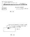
- FIG. 4 shows the location on a document of the pixels from the scanning element.
- FIG. 5 shows how the data from the scanner is combined.
- FIG. 6 shows a preferred embodiment of the invention.
- FIG. 1 An overall diagram illustrating the present invention applied to a flatbed scanner is shown in FIG. 1 .
- the scanner shown in FIG. 1 has a scanner bed 10 on which is position a document 11 .
- a moveable scanning carriage 12 contains a light source 13 and a linear array of charge coupled devices (CCDs) 14 .
- a line on the document 11 is illuminated by LED light source 13 .
- An image of the illuminated line is focused on CCD detector array 14 by a lens (not explicitly shown).
- the array 14 is moved across the document in the y direction (by a conventional mechanical mechanism which is not explicitly shown in the drawing).
- a microprocessor 20 controls the operation of the entire system and signals from the CCD array 14 are stored in memory 20 A.
- the signals from array 14 creates a digital image of the document in micro-processor memory 20 A. All of the above elements are conventional and they are found in many commercially available flatbed scanners.
- the present invention involves transducer 15 which is positioned at the end of array 14 and which will be described later with reference to FIGS. 2A and 2B.
- FIG. 3A illustrates the image of document 10 which would be created in memory 20 A if the system operated in a conventional manner without the present invention.
- the image has pixels 10 a , 10 b , 10 c , etc. arranged in uniform rows and columns.
- the memory 20 A stores a number for each pixel which indicates the intensity of that pixel.
- a color scanner would store three numbers for each pixel to indicate the intensity of each of the tree primary colors in each pixel.
- the preferred embodiment of the invention will be described as a single color (i.e. a black and white) scanner. However, the invention can be extended to a color scanner by handling each color in the same manner that a single color is handled in the embodiment described herein.
- the speed at which the array 14 is moved in the “y” direction and the rate at which the CCD devices 14 are read must be coordinated. For example in a scanner which is designed to create an image with 600 pixels per inch, if the time required for the array 14 to move ⁇ fraction (1/600) ⁇ th of an inch is one millisecond, a reading must be taken from the CCD elements in array 14 each millisecond. That is, the rate at which data is read from CCD devices in array 14 must be coordinated with the speed that the array 14 is moved in the “y” direction so that a new row of pixels is in position to be read each time the CCD elements in array 14 are read.
- Scanners which produces the type of image illustrated in FIG. 3A are commercially available.
- the difference between the present invention and the prior art relates to the transducer unit 15 which moves or vibrates the array 14 in the “x” direction.
- the CCD scanning array 14 has a large number individual CCD devices 14 a , 14 b , 14 c etc.
- One end of the scanning array 14 is attached to transducer unit 15 which may be a piezo electric crystal.
- the piezo electric transducer 15 is attached to stationary frame 18 .
- the array of CCD devices is free to move in the x direction (i.e. directions 28 and 29 ) by sliding in a channel or grove in frame 18 .
- the scanning array 14 is moved in the x direction (i.e. in directions 28 and 29 ) by an amount equal to one half a pixel size each time a row of pixels is read.
- the sequence of steps is:
- the scanning element is moved to the left (direction 29 ) by one half a pixel, and
- FIG. 3 shows the position of CCD scanning array 14 at three different times T 1 , T 2 , and T 3 .
- the CCD devices 14 a , 14 b , 14 c , etc. are shown in an expanded view and thus all of the elements in array 14 can not be shown on the figure.
- the movement of the array 14 in the “y” direction along the document is in fact continuous and the positions discussed here are the positions of the array at the specific times that the CCD devices are sampled or read.
- the scanning array 14 is in what will be called the “home” position.
- the array 14 moves one pixel position in the “y” direction and the array 14 is moved one half a pixel position in the “x” direction 28 .
- a second set of values is then read from the CCD devices 25 Next the array moves one more pixel position in the “y” direction and the array 14 is moved one half a pixel position back to the home position. The process is then repeated.
- FIG. 4 shows the document 11 with an indication of the location of the pixels that are read by CCD elements 14 a , 14 b , 14 c , etc. It is noted that the edge portions of the document are ignored and only the information in the area designated by line 41 is of interest. It is also noted that since the document is shown enlarged in FIG. 4, only the top left corner of the document is shown.
- the pixels in each row of the document are designated as by two numbers.
- the first number indicates the row where the pixel is located and the second number indicates the position of the pixel in the row.
- the third pixel in the second row is designated as “2,3”.
- FIG. 5 illustrates the data in memory 17 which represents the data from area 41 of document 11 .
- FIG. 5 represents an array of numbers stored in a memory in a conventional manner to represent an image. The images are arranged in rows and columns. Two letters are used to represent each number. For example “B,C” represents the third number in the second row. The number “B,C” is a number stored in memory 20 A which represents the value of a particular pixel in the image.
- the values represented in FIG. 5 are calculated from the values read from the CCD devices as they scan each of the pixels shown in FIG. 4 .
- the values in the first row are the direct values read from the scanning elements.
- value “A,B” is the value read from a CCD element as it scans pixel “1,3” shown in FIG. 4 .
- the values in row B are calculated values.
- value “B,A” is derived from the values read from the CCD elements as they scan pixels “2,1” and “2,2”.
- the value of “B,A” is one half the value of “2,1” plus one half the value of “2,2”.
- the reason for this is that the value “B,A” represents a pseudo pixel that is located half way between pixels “2,1” and “2,2”.
- Each of the other values for the values in rows 2, 4, 6, etc. are calculated in like fashion.
- a first set of values is read when the scanning array 14 is in position shown in T 1 in FIG. 3 .
- the array 14 is moved in the “y” direction by an amount equal to one pixel position and the scanning array 14 is moved one half a pixel position in the “x” direction 28 and a second set of values are read from the scanning array 14 .
- the process then continues as previous explained. If the values read as described above were directly printed, on a conventional printer, the image would be distorted, since a printer prints the value of the pixels in the second row of an image directly beneath and aligned with the pixels in the first row of an image.
- the calculation of he value of the pseudo pixels is relatively easy since the scanning element is moved a uniform one half pixel amount between each scan row. In the preferred embodiment of the invention shown in FIG. 6 and described below, the calculation becomes somewhat more complicated.
- the scanning element 25 is moved in accordance with a pseudo random pattern.
- the pseudo random pattern has fifteen different values between 10 and 90 percent. Each value represents the percent of the width of a pixel which the scanning element is moved during a particular time period.
- the scanner might be moved by the following amounts over fifteen rows of pixels:
- FIG. 6 A system which utilizes a series of random numbers to determine the amount of movement between rows of pixels is shown in FIG. 6 .
- the CCD scanner 25 and the driver 26 are similar to the previous embodiment.
- the series of numbers which specify the amount of movement are stored in memory 63 .
- a driver control 27 reads the numbers from memory 63 and sequentially activates the driver 26 with signals which have a magnitude controlled by the numbers in storage 63 .
- the output of the scanner goes to memory 61 .
- the calculating device 65 combines the values from memory 61 into a final image based upon the amount of movement of each line.
- the numbers in the final image was calculated by taking one half of the value of two pixels.
- the calculation is somewhat more complicated. For example is the movement is 0.25 of a pixel, the final value of a pixel would be calculated by taking 0.25% of the value of one value and 0.75% of another value.
- FIG. 6 shows a number of discrete components. It should be recognized that the components shown in FIG. 6, could be discrete components; however, they could also be subroutines and area of memory in a single conventional computer.
- the present invention can also be used to enhance patterns which are intentionally places in an image. That is, the present invention can be utilized to detect special patterns which are placed in an image and which can only be detected by a scanner which operates according to the present invention
- each scanned pixels would cover three of the original pixels and have one of the following values (where the numbers “24” and “21” indicate the values of the scanned pixels.
- the underlining shows the pixels in the original that are grouped together in the scanned pixels.:
- the patterns would be as follows:
- the above described technique can be used to facilitate the determination if documents are originals or copies.
- a pattern can be printed in a document which can only be detected by a scanner which has an array of elements that moves in a particular patterns. If such a document is scanned on a conventional scanner and then reproduced, the intensity of the hidden image will be reduced or destroyed.
- a color scanner generally has three rows of detectors, one for each color. These detectors could all be moved together in the “x” direction or more complicated patterns could be created by moving the detectors for each pattern in accordance with a different pattern of movement.
- the present invention may not entirely eliminate Moiré patterns in all instances. However on a stochastic basis the present invention will minimize Moiré patterns in most conventional images.
- the detector elements are moved in the “x” direction while the document is canned in the “y” direction. In certain applications it may be desirable to move the detector elements in a direction other than in the “x” direction.
- the mechanism for moving array 14 in a “y” direction can be conventional.
- the array 14 could be mounted on rollers and spring biased to move in one “y”direction.
- An electric motor with a small cable could pull the array 14 against the spring bias in order to move the array over an document during the scanning operation.
Abstract
Description
| 69966996699669966996699669966996699669966996 | |
| 69966996699669966996699669966996699669966996 | |
| 69966996699669966996699669966996699669966996 |
| 69966996699669966996699669966996699669966996 |
| 24 21 21 24 24 21 21 |
| 69966996699669966996699669966996699669966996 |
| 24 24 21 21 24 24 |
| 69966996699669966996699669966996699669966996 |
| 21 24 24 21 21 |
| 24 21 21 24 24 21 21 | |
| 24 21 21 24 24 21 21 | |
| 24 21 21 24 24 21 21 | |
| 24 21 21 24 24 21 21 | |
| or | |
| 24 24 21 21 24 24 | |
| 24 24 21 21 24 24 | |
| 24 24 21 21 24 24 | |
| 24 24 21 21 24 24 | |
| or | |
| 21 24 24 21 21 | |
| 21 24 24 21 21 | |
| 21 24 24 21 21 | |
| 21 24 24 21 21 |
| 24 21 21 24 24 21 21 | |
| 24 24 21 21 24 24 21 21 | |
| 24 21 21 24 24 21 21 | |
| 24 24 21 21 24 24 21 21 | |
| or | |
| 24 24 21 21 24 24 | |
| 21 24 24 21 21 24 24 | |
| 24 24 21 21 24 24 | |
| 21 24 24 21 21 24 24 | |
| or | |
| 21 24 24 21 21 | |
| 21 21 24 24 21 21 | |
| 21 24 24 21 21 | |
| 21 21 24 24 21 21 |
Claims (12)
Priority Applications (3)
| Application Number | Priority Date | Filing Date | Title |
|---|---|---|---|
| US09/930,603 US6631015B2 (en) | 1998-06-18 | 2001-08-15 | Stochastic scanning documents to change Moire effects |
| US10/678,584 US7656565B2 (en) | 1998-06-18 | 2003-10-03 | Exploiting random motion during scanning to yield improved image |
| US12/694,518 US8203766B2 (en) | 1998-06-18 | 2010-01-27 | Vibratory scanning |
Applications Claiming Priority (2)
| Application Number | Priority Date | Filing Date | Title |
|---|---|---|---|
| US09/099,864 US6320680B1 (en) | 1998-06-18 | 1998-06-18 | Stochastic scanning documents to change moire effects |
| US09/930,603 US6631015B2 (en) | 1998-06-18 | 2001-08-15 | Stochastic scanning documents to change Moire effects |
Related Parent Applications (1)
| Application Number | Title | Priority Date | Filing Date |
|---|---|---|---|
| US09/099,864 Continuation US6320680B1 (en) | 1998-06-18 | 1998-06-18 | Stochastic scanning documents to change moire effects |
Related Child Applications (1)
| Application Number | Title | Priority Date | Filing Date |
|---|---|---|---|
| US10/678,584 Continuation US7656565B2 (en) | 1998-06-18 | 2003-10-03 | Exploiting random motion during scanning to yield improved image |
Publications (2)
| Publication Number | Publication Date |
|---|---|
| US20020075531A1 US20020075531A1 (en) | 2002-06-20 |
| US6631015B2 true US6631015B2 (en) | 2003-10-07 |
Family
ID=22276989
Family Applications (4)
| Application Number | Title | Priority Date | Filing Date |
|---|---|---|---|
| US09/099,864 Expired - Lifetime US6320680B1 (en) | 1998-06-18 | 1998-06-18 | Stochastic scanning documents to change moire effects |
| US09/930,603 Expired - Lifetime US6631015B2 (en) | 1998-06-18 | 2001-08-15 | Stochastic scanning documents to change Moire effects |
| US10/678,584 Expired - Fee Related US7656565B2 (en) | 1998-06-18 | 2003-10-03 | Exploiting random motion during scanning to yield improved image |
| US12/694,518 Expired - Fee Related US8203766B2 (en) | 1998-06-18 | 2010-01-27 | Vibratory scanning |
Family Applications Before (1)
| Application Number | Title | Priority Date | Filing Date |
|---|---|---|---|
| US09/099,864 Expired - Lifetime US6320680B1 (en) | 1998-06-18 | 1998-06-18 | Stochastic scanning documents to change moire effects |
Family Applications After (2)
| Application Number | Title | Priority Date | Filing Date |
|---|---|---|---|
| US10/678,584 Expired - Fee Related US7656565B2 (en) | 1998-06-18 | 2003-10-03 | Exploiting random motion during scanning to yield improved image |
| US12/694,518 Expired - Fee Related US8203766B2 (en) | 1998-06-18 | 2010-01-27 | Vibratory scanning |
Country Status (3)
| Country | Link |
|---|---|
| US (4) | US6320680B1 (en) |
| AU (1) | AU4681099A (en) |
| WO (1) | WO1999066379A2 (en) |
Cited By (2)
| Publication number | Priority date | Publication date | Assignee | Title |
|---|---|---|---|---|
| US20040130758A1 (en) * | 1998-06-18 | 2004-07-08 | Rhoads Geoffrey B. | Exploiting random motion during scanning to yield improved image |
| US20110033089A1 (en) * | 2009-08-06 | 2011-02-10 | Kazuaki Yokota | Apparatus for appraising the genuineness of personal identification documents |
Families Citing this family (8)
| Publication number | Priority date | Publication date | Assignee | Title |
|---|---|---|---|---|
| US6956963B2 (en) * | 1998-07-08 | 2005-10-18 | Ismeca Europe Semiconductor Sa | Imaging for a machine-vision system |
| JP4032527B2 (en) * | 1998-10-05 | 2008-01-16 | コニカミノルタビジネステクノロジーズ株式会社 | Image reading device |
| US6788411B1 (en) * | 1999-07-08 | 2004-09-07 | Ppt Vision, Inc. | Method and apparatus for adjusting illumination angle |
| WO2004072659A2 (en) * | 2003-02-07 | 2004-08-26 | University Of Southern California | Reflectometry apparatus and method |
| DE102006041462B3 (en) * | 2006-09-04 | 2008-01-03 | Chromasens Gmbh | Optical scanning method for documents with line camera, involves scanning document which is guided with variable transportation speed and line frequency |
| US9726818B1 (en) * | 2013-05-30 | 2017-08-08 | Hrl Laboratories, Llc | Multi-wavelength band optical phase and amplitude controller |
| US9485380B2 (en) * | 2014-06-25 | 2016-11-01 | Fuji Xerox Co., Ltd. | Image reading apparatus, image forming apparatus and computer readable medium storing program |
| CN105260152B (en) * | 2015-10-09 | 2018-05-08 | 利亚德光电股份有限公司 | Image processing method and device for LED display |
Citations (19)
| Publication number | Priority date | Publication date | Assignee | Title |
|---|---|---|---|---|
| US4326147A (en) | 1975-08-18 | 1982-04-20 | Hitachi, Ltd. | Slotted shadow mask having apertures spaced to minimize moire |
| US4336558A (en) | 1980-04-23 | 1982-06-22 | American Hoechst Corp. | Imaging system and method with reduced moire interference |
| US4468706A (en) | 1979-02-13 | 1984-08-28 | Coulter Systems Corporation | Imaging by varying the placement of elements in the pixels |
| US4516175A (en) | 1981-05-20 | 1985-05-07 | Dr. Ing. Rudolf Hell Gmbh | Scanning method and scanning diaphragm for suppressing Moire in the scanning of rastered masters |
| US4613896A (en) | 1984-03-30 | 1986-09-23 | Dainippon Screen Mfg. Co., Ltd. | Methods and apparatus for avoiding moire in color scanners for graphic art |
| US4689514A (en) | 1985-06-10 | 1987-08-25 | Kabushiki Kaisha Toshiba | Displacement generating device |
| US4743927A (en) | 1985-12-16 | 1988-05-10 | Brother Kogyo Kabushiki Kaisha | Printing apparatus |
| US4965599A (en) | 1989-11-13 | 1990-10-23 | Eastman Kodak Company | Scanning apparatus for halftone image screen writing |
| US5069530A (en) | 1989-02-21 | 1991-12-03 | Nippon Hoso Kyokai | Solid state image pick-up apparatus |
| US5121213A (en) | 1987-02-25 | 1992-06-09 | Olympus Optical Co., Ltd. | Imaging system having a blurring optical element for minimizing moire phenomenon |
| US5335091A (en) | 1991-12-31 | 1994-08-02 | Eastman Kodak Company | Apparatus for mechanically dithering a CCD array |
| US5374976A (en) | 1990-12-13 | 1994-12-20 | Joh. Enschede En Zonen Grafische Inrichting B.V. | Support provided with a machine detectable copying security element |
| US5396142A (en) | 1994-01-24 | 1995-03-07 | Evan Koblanski | Positioning apparatus |
| US5489994A (en) | 1993-10-29 | 1996-02-06 | Eastman Kodak Company | Integrated apertures on a full frame CCD image sensor |
| US5541741A (en) | 1991-09-30 | 1996-07-30 | Canon Kabushiki Kaisha | Image processing with anti-forgery provision |
| US5751444A (en) | 1995-12-18 | 1998-05-12 | Adobe Systems Incorporated | Imaging apparatus for copying bound documents |
| US5786901A (en) | 1995-05-30 | 1998-07-28 | Sharp Kabushiki Kaisha | Image shifting mechanism and imaging device |
| US6115147A (en) * | 1996-10-01 | 2000-09-05 | Fuji Photo Film Co., Ltd. | Image reading apparatus |
| US6320680B1 (en) * | 1998-06-18 | 2001-11-20 | Digimarc Corporation | Stochastic scanning documents to change moire effects |
Family Cites Families (8)
| Publication number | Priority date | Publication date | Assignee | Title |
|---|---|---|---|---|
| US578223A (en) * | 1897-03-02 | Currycomb | ||
| EP0670528B1 (en) * | 1987-08-11 | 1998-12-23 | Canon Kabushiki Kaisha | Color image processing apparatus |
| KR950001076B1 (en) * | 1992-05-12 | 1995-02-08 | 주식회사 금성사 | Heater fabricating method of electron gun for crt |
| US5767987A (en) * | 1994-09-26 | 1998-06-16 | Ricoh Corporation | Method and apparatus for combining multiple image scans for enhanced resolution |
| JP3237452B2 (en) * | 1995-04-20 | 2001-12-10 | 富士ゼロックス株式会社 | Image writing device |
| US5859928A (en) * | 1996-06-21 | 1999-01-12 | Hewlett-Packard Company | Jitter-form background control for minimizing spurious gray cast in scanned images |
| US6240219B1 (en) * | 1996-12-11 | 2001-05-29 | Itt Industries Inc. | Apparatus and method for providing optical sensors with super resolution |
| JPH10341367A (en) * | 1997-06-06 | 1998-12-22 | Toshiba Corp | Still image generating method and still image fetch system |
-
1998
- 1998-06-18 US US09/099,864 patent/US6320680B1/en not_active Expired - Lifetime
-
1999
- 1999-06-14 AU AU46810/99A patent/AU4681099A/en not_active Abandoned
- 1999-06-14 WO PCT/US1999/013320 patent/WO1999066379A2/en active Search and Examination
-
2001
- 2001-08-15 US US09/930,603 patent/US6631015B2/en not_active Expired - Lifetime
-
2003
- 2003-10-03 US US10/678,584 patent/US7656565B2/en not_active Expired - Fee Related
-
2010
- 2010-01-27 US US12/694,518 patent/US8203766B2/en not_active Expired - Fee Related
Patent Citations (19)
| Publication number | Priority date | Publication date | Assignee | Title |
|---|---|---|---|---|
| US4326147A (en) | 1975-08-18 | 1982-04-20 | Hitachi, Ltd. | Slotted shadow mask having apertures spaced to minimize moire |
| US4468706A (en) | 1979-02-13 | 1984-08-28 | Coulter Systems Corporation | Imaging by varying the placement of elements in the pixels |
| US4336558A (en) | 1980-04-23 | 1982-06-22 | American Hoechst Corp. | Imaging system and method with reduced moire interference |
| US4516175A (en) | 1981-05-20 | 1985-05-07 | Dr. Ing. Rudolf Hell Gmbh | Scanning method and scanning diaphragm for suppressing Moire in the scanning of rastered masters |
| US4613896A (en) | 1984-03-30 | 1986-09-23 | Dainippon Screen Mfg. Co., Ltd. | Methods and apparatus for avoiding moire in color scanners for graphic art |
| US4689514A (en) | 1985-06-10 | 1987-08-25 | Kabushiki Kaisha Toshiba | Displacement generating device |
| US4743927A (en) | 1985-12-16 | 1988-05-10 | Brother Kogyo Kabushiki Kaisha | Printing apparatus |
| US5121213A (en) | 1987-02-25 | 1992-06-09 | Olympus Optical Co., Ltd. | Imaging system having a blurring optical element for minimizing moire phenomenon |
| US5069530A (en) | 1989-02-21 | 1991-12-03 | Nippon Hoso Kyokai | Solid state image pick-up apparatus |
| US4965599A (en) | 1989-11-13 | 1990-10-23 | Eastman Kodak Company | Scanning apparatus for halftone image screen writing |
| US5374976A (en) | 1990-12-13 | 1994-12-20 | Joh. Enschede En Zonen Grafische Inrichting B.V. | Support provided with a machine detectable copying security element |
| US5541741A (en) | 1991-09-30 | 1996-07-30 | Canon Kabushiki Kaisha | Image processing with anti-forgery provision |
| US5335091A (en) | 1991-12-31 | 1994-08-02 | Eastman Kodak Company | Apparatus for mechanically dithering a CCD array |
| US5489994A (en) | 1993-10-29 | 1996-02-06 | Eastman Kodak Company | Integrated apertures on a full frame CCD image sensor |
| US5396142A (en) | 1994-01-24 | 1995-03-07 | Evan Koblanski | Positioning apparatus |
| US5786901A (en) | 1995-05-30 | 1998-07-28 | Sharp Kabushiki Kaisha | Image shifting mechanism and imaging device |
| US5751444A (en) | 1995-12-18 | 1998-05-12 | Adobe Systems Incorporated | Imaging apparatus for copying bound documents |
| US6115147A (en) * | 1996-10-01 | 2000-09-05 | Fuji Photo Film Co., Ltd. | Image reading apparatus |
| US6320680B1 (en) * | 1998-06-18 | 2001-11-20 | Digimarc Corporation | Stochastic scanning documents to change moire effects |
Cited By (5)
| Publication number | Priority date | Publication date | Assignee | Title |
|---|---|---|---|---|
| US20040130758A1 (en) * | 1998-06-18 | 2004-07-08 | Rhoads Geoffrey B. | Exploiting random motion during scanning to yield improved image |
| US7656565B2 (en) * | 1998-06-18 | 2010-02-02 | Digimarc Corporation | Exploiting random motion during scanning to yield improved image |
| US20110026086A1 (en) * | 1998-06-18 | 2011-02-03 | Rhoads Geoffrey B | Vibratory Scanning |
| US8203766B2 (en) * | 1998-06-18 | 2012-06-19 | Digimarc Corporation | Vibratory scanning |
| US20110033089A1 (en) * | 2009-08-06 | 2011-02-10 | Kazuaki Yokota | Apparatus for appraising the genuineness of personal identification documents |
Also Published As
| Publication number | Publication date |
|---|---|
| US20040130758A1 (en) | 2004-07-08 |
| US6320680B1 (en) | 2001-11-20 |
| WO1999066379A3 (en) | 2000-04-06 |
| US7656565B2 (en) | 2010-02-02 |
| WO1999066379A2 (en) | 1999-12-23 |
| US8203766B2 (en) | 2012-06-19 |
| AU4681099A (en) | 2000-01-05 |
| US20110026086A1 (en) | 2011-02-03 |
| US20020075531A1 (en) | 2002-06-20 |
Similar Documents
| Publication | Publication Date | Title |
|---|---|---|
| US8203766B2 (en) | Vibratory scanning | |
| US5532845A (en) | High speed high resolution platen scanning system using a plurality of scanning units | |
| US6181441B1 (en) | Scanning system and method for stitching overlapped image data by varying stitch location | |
| JPH07231384A (en) | Digital recorder | |
| US6381377B1 (en) | Generating a high resolution scan image with a low resolution scan sensor | |
| CA1181838A (en) | Method of improving contrast accentuation | |
| EP1170937A2 (en) | High speed scanner using multiple sensing devices | |
| US7400430B2 (en) | Detecting and compensating for color misregistration produced by a color scanner | |
| US5537226A (en) | Method for restoring images scanned in the presence of vibration | |
| EP0296806B1 (en) | An image sensing apparatus with shading compensation | |
| JP3086520B2 (en) | Playback image quality evaluation device | |
| JP2005524268A (en) | Whole image formation by sampling a partial area of a document | |
| CA2129090C (en) | Apparatus and method for screening images for reproduction | |
| US6282331B1 (en) | Apparatus of alignment for scanner and a method of the same | |
| JP3163703B2 (en) | Document reading device | |
| WO1992009167A1 (en) | Scanning speed compensation | |
| KR930010023B1 (en) | Sampling system for fax | |
| JP3526216B2 (en) | Image processing device | |
| JP3597586B2 (en) | Image reading device | |
| JP2522707B2 (en) | Image pickup device | |
| JP3527412B2 (en) | Image processing device | |
| JPH09102914A (en) | Optical system | |
| JPH04351171A (en) | Picture processing unit | |
| GB2323233A (en) | Compensating for video signal distortion produced by document scanning movement in a digital scanner | |
| WO1991011878A1 (en) | Production of test prints from a full page image buffer |
Legal Events
| Date | Code | Title | Description |
|---|---|---|---|
| STCF | Information on status: patent grant |
Free format text: PATENTED CASE |
|
| FPAY | Fee payment |
Year of fee payment: 4 |
|
| AS | Assignment |
Owner name: DIGIMARC CORPORATION (FORMERLY DMRC CORPORATION), Free format text: CONFIRMATION OF TRANSFER OF UNITED STATES PATENT RIGHTS;ASSIGNOR:L-1 SECURE CREDENTIALING, INC. (FORMERLY KNOWN AS DIGIMARC CORPORATION);REEL/FRAME:021785/0796 Effective date: 20081024 Owner name: DIGIMARC CORPORATION (FORMERLY DMRC CORPORATION), OREGON Free format text: CONFIRMATION OF TRANSFER OF UNITED STATES PATENT RIGHTS;ASSIGNOR:L-1 SECURE CREDENTIALING, INC. (FORMERLY KNOWN AS DIGIMARC CORPORATION);REEL/FRAME:021785/0796 Effective date: 20081024 Owner name: DIGIMARC CORPORATION (FORMERLY DMRC CORPORATION),O Free format text: CONFIRMATION OF TRANSFER OF UNITED STATES PATENT RIGHTS;ASSIGNOR:L-1 SECURE CREDENTIALING, INC. (FORMERLY KNOWN AS DIGIMARC CORPORATION);REEL/FRAME:021785/0796 Effective date: 20081024 |
|
| AS | Assignment |
Owner name: DIGIMARC CORPORATION (AN OREGON CORPORATION), OREGON Free format text: MERGER;ASSIGNOR:DIGIMARC CORPORATION (A DELAWARE CORPORATION);REEL/FRAME:024369/0582 Effective date: 20100430 Owner name: DIGIMARC CORPORATION (AN OREGON CORPORATION),OREGO Free format text: MERGER;ASSIGNOR:DIGIMARC CORPORATION (A DELAWARE CORPORATION);REEL/FRAME:024369/0582 Effective date: 20100430 Owner name: DIGIMARC CORPORATION (AN OREGON CORPORATION), OREG Free format text: MERGER;ASSIGNOR:DIGIMARC CORPORATION (A DELAWARE CORPORATION);REEL/FRAME:024369/0582 Effective date: 20100430 |
|
| AS | Assignment |
Owner name: DIGIMARC CORPORATION (A DELAWARE CORPORATION), ORE Free format text: MERGER;ASSIGNOR:DIGIMARC CORPORATION (AN OREGON CORPORATION);REEL/FRAME:024982/0707 Effective date: 19991124 |
|
| AS | Assignment |
Owner name: DIGIMARC CORPORATION, OREGON Free format text: ASSIGNMENT OF ASSIGNORS INTEREST;ASSIGNOR:RHOADS, GEOFFREY B.;REEL/FRAME:025178/0829 Effective date: 19980618 |
|
| AS | Assignment |
Owner name: DMRC LLC, OREGON Free format text: ASSIGNMENT OF ASSIGNORS INTEREST;ASSIGNOR:DIGIMARC CORPORATION (A DELAWARE CORPORATION);REEL/FRAME:025217/0508 Effective date: 20080801 |
|
| AS | Assignment |
Owner name: DIGIMARC CORPORATION, OREGON Free format text: MERGER;ASSIGNOR:DMRC CORPORATION;REEL/FRAME:025227/0832 Effective date: 20080903 Owner name: DMRC CORPORATION, OREGON Free format text: MERGER;ASSIGNOR:DMRC LLC;REEL/FRAME:025227/0808 Effective date: 20080801 |
|
| FEPP | Fee payment procedure |
Free format text: PAYOR NUMBER ASSIGNED (ORIGINAL EVENT CODE: ASPN); ENTITY STATUS OF PATENT OWNER: LARGE ENTITY |
|
| FPAY | Fee payment |
Year of fee payment: 8 |
|
| FPAY | Fee payment |
Year of fee payment: 12 |