US6630063B1 - Uniform laser excitation and detection in capillary array electrophoresis system and method - Google Patents
Uniform laser excitation and detection in capillary array electrophoresis system and method Download PDFInfo
- Publication number
- US6630063B1 US6630063B1 US09/413,355 US41335599A US6630063B1 US 6630063 B1 US6630063 B1 US 6630063B1 US 41335599 A US41335599 A US 41335599A US 6630063 B1 US6630063 B1 US 6630063B1
- Authority
- US
- United States
- Prior art keywords
- capillaries
- group
- scanning mirror
- laser beam
- samples
- Prior art date
- Legal status (The legal status is an assumption and is not a legal conclusion. Google has not performed a legal analysis and makes no representation as to the accuracy of the status listed.)
- Expired - Lifetime
Links
Images


Classifications
-
- G—PHYSICS
- G01—MEASURING; TESTING
- G01N—INVESTIGATING OR ANALYSING MATERIALS BY DETERMINING THEIR CHEMICAL OR PHYSICAL PROPERTIES
- G01N27/00—Investigating or analysing materials by the use of electric, electrochemical, or magnetic means
- G01N27/26—Investigating or analysing materials by the use of electric, electrochemical, or magnetic means by investigating electrochemical variables; by using electrolysis or electrophoresis
- G01N27/416—Systems
- G01N27/447—Systems using electrophoresis
- G01N27/44704—Details; Accessories
- G01N27/44717—Arrangements for investigating the separated zones, e.g. localising zones
- G01N27/44721—Arrangements for investigating the separated zones, e.g. localising zones by optical means
-
- G—PHYSICS
- G01—MEASURING; TESTING
- G01N—INVESTIGATING OR ANALYSING MATERIALS BY DETERMINING THEIR CHEMICAL OR PHYSICAL PROPERTIES
- G01N27/00—Investigating or analysing materials by the use of electric, electrochemical, or magnetic means
- G01N27/26—Investigating or analysing materials by the use of electric, electrochemical, or magnetic means by investigating electrochemical variables; by using electrolysis or electrophoresis
- G01N27/416—Systems
- G01N27/447—Systems using electrophoresis
- G01N27/44756—Apparatus specially adapted therefor
- G01N27/44782—Apparatus specially adapted therefor of a plurality of samples
Definitions
- This invention relates to a laser illumination and detection system for performing sample analysis, such as DNA sequencing, DNA fingerprinting, absorption/emission spectroscopy, and the like. More particularly, it pertains to a laser illumination system that employs a laser scanner.
- a conventional capillary array electrophoresis system is configured to perform a high-throughput analysis on biological samples, e.g., DNA sequencing, using a highly sensitive laser-induced fluorescence detection method.
- biological samples e.g., DNA sequencing
- the samples to be analyzed either possess fluorescing functional groups (fluorophores) in their molecular structure or are tagged with fluorescent dyes. These samples are then excited with a laser beam which causes the samples to emit fluorescence light. The emitted fluorescence light is detected and subsequently analyzed.
- the samples are illuminated by the laser beam either while they are still migrating through the capillaries, i.e., on-column detection, or after they elute from output ends of the capillaries, i.e., sheath-flow detection, as described by Dovichi et al. (U.S. Pat. No. 5,741,412).
- samples in the confocal microscope scanning method can be used as described in Mathies el al. (U.S. Pat. No. 5,274,240) In this method, samples in each capillary are sequentially excited and detected by a confocal scanning system. In another method, as described by Yeung et al,(U.S. Pat. No. 5,741,411) all the capillaries are illuminated by a laser beam and monitored by a 2-dimensional charged couple device (CCD) simultaneously.
- CCD 2-dimensional charged couple device
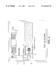
- FIG. 1 illustrates a conventional on-column detection system 1 that includes a laser light source 3 illuminating a capillary array 5 and samples therein and a camera lens 7 receiving the emitted light from the samples. Subsequently, the received light from the samples is captured by a CCD and analyzed.
- FIG. 2 shows an intensity profile, amounts of light received across a viewing field of the camera 7 . More specifically, the measurements are made by illuminating a laser beam on the array of capillaries 5 having the same quantity of samples migrating through each of the capillaries.
- the view field of the camera 7 is about 2 cm, i.e., the width of a 96 capillary array comprising capillaries with 200 ⁇ m outside diameters (o.d.)laid side by side.
- the position of 300 in FIG. 2 corresponds to the center of the array.
- the resulting intensity profile shows that the amount of the light received from the location near the center of the array is more than that from capillaries at the periphery of the array.
- the laser beam has a Gaussian beam profile.
- a laser beam produced by a conventional laser illuminates the capillaries in the middle portion with about 1.5 times more intensity than the capillaries at the periphery of the array.
- the amount of light captured by the camera varies based on the location of the capillaries. In particular, the amount of light received by the camera from a unit area of the capillaries at the periphery of the array is less than that from a unit area of the capillary at the center of the array, when an identical amount of light is emitted by the samples within the capillaries in each of the unit areas.
- the above discussed shortcomings of the conventional system produce a non-uniform intensity profile.
- the amounts of light received from the center capillaries and periphery capillaries can differ by a factor of 2-4, as shown in FIG. 2 .
- the non-uniform intensity profile is not desirable, because in order to obtain sufficient amounts of light from the capillaries at the periphery of the array, the strength of the laser beam illuminating the center of the array may saturate the camera. Further, in order to process and analyze the data collected under this condition for capillary-to-capillary comparison and quantification, the subsequent analysis. process becomes complicated.
- the present invention therefore, provides a capillary electrophoresis system that includes capillaries positioned parallel to each other to form a plane.
- the capillaries are configured to allow samples to migrate therethrough.
- the system further includes a light source configured to illuminate the capillaries and the samples therein. This causes the samples to emit light.
- the system also includes a lens configured to receive the light emitted by the sample. The lens is positioned directly over a first group of the capillaries and obliquely over a second group of the capillaries.
- the light source is further configured to illuminate the second group of capillaries more than the first group of the capillaries such that amount of light received by the lens from the first group of capillaries is substantially identical to amount of light received from the second group of capillaries when an identical amount of the samples is migrating through the first and second group capillaries.
- the light source further includes a laser configured to produce a laser beam and a scanning mirror optically coupled to the laser to receive the laser beam.
- the scanning mirror is configured to be oscillated and positioned to aim the received laser beam at the capillaries.
- the light source further includes a control device operatively coupled to the scanning mirror. The control device is configured to control the oscillation of the scanning mirror. This causes the laser beam from the scanning mirror to illuminate the plurality of capillaries.
- the plane formed by the plurality of capillaries has a coincident axis extending parallel to the lengths of the capillaries.
- the scanning mirror aims the laser beam through a scanning plane which is formed by a locus of the laser beam illuminating the capillaries.
- the laser beam impinges on the capillaries at an angle of 45°-90° formed between the scanning plane and the coincident axis.
- the plane formed by the plurality of capillaries also has a transverse axis extending parallel to the widths of the capillaries.
- the scanning plane has a central beam line extending from the scanning mirror to a center point among the capillaries illuminated by the laser beam. The laser beam impinges on the capillaries at an angle of 1°-90° formed between the transverse axis and the central beam line.
- the present invention also provides a capillary electrophoresis method that includes the steps of introducing samples to a plurality of capillaries positioned in parallel to each other forming a plane and forming a first group and a second group of capillaries, and causing the samples to migrate through the capillaries.
- the method also includes the step of illuminating the second group of capillaries more than the first group of the capillaries such that amount of light received by a lens from the first group of capillaries is substantially identical to amount of light received from the second group of capillaries when an identical amount of the samples is migrating through the first and second group capillaries.
- the lens is positioned directly above the first group of capillaries and obliquely over the second group of capillaries.
- the method also includes the steps of measuring amount of light received by the lens from the first and second groups of capillaries, while injecting an identical amount of the samples into the first and second capillaries, and while illuminating the first and second groups of capillaries with a substantially identical amount of light. Subsequently, a difference between the amount of light received by the lens from the first and second groups of capillaries is calculated.
- the illuminating step further includes the steps of generating a compensating laser beam that substantially eliminates the calculated difference.
- the capillaries are illuminated by the compensating laser beam.
- FIG. 1 shows a conventional capillary electrophoresis system
- FIG. 2 illustrates a non-uniform intensity profile of a conventional system
- FIG. 3 shows a top view of the capillary electrophoresis system of the present invention
- FIG. 4 shows a frontal view of the capillary electrophoresis system of the present invention
- FIG. 5 shows an optical coupler that includes a scanner and a convex lens
- FIG. 5A shows an exploded view of the scanning assembly
- FIG. 6 shows an optical coupler that includes a scanner and a cylindrical lens
- FIG. 6A shows an exploded view of the scanning assembly
- FIG. 7 illustrates an angle between the plane of the expanded laser beam and the capillary array
- FIG. 8 illustrates an angle between the central beam of an expanded laser beam and the capillary array
- FIG. 9 illustrates generation of uniform intensity profile
- FIGS. 9 a - 9 c shows an intensity compensation procedure of the present invention.
- FIG. 10 illustrates an intensity profile using 150 Hz sinusoidal waveforms.
- the laser illumination and detection system of the present invention includes a laser 21 , an optical coupler 23 and a scanner assembly 25 .
- the system further includes a detection system 27 and a housing 29 which receives a number of capillaries 31 .
- the capillaries 31 allows biological samples to migrate therethrough from input ends 33 to output ends 35 .
- the samples are preferably biological samples, e.g., DNA samples, that either possess fluorescing functional groups (fluorophores) in their molecular structure or are tagged with fluorescent dyes.
- the laser 21 preferably is an air-cooled argon ion laser that produces a light beam comprising of one, single emission mode, or multiple wavelengths, multi-wavelength emission mode.
- the wavelength is usually 488 nm or 514 nm.
- the wavelength may include any combination of 456 nm, 476 nm, 488 nm, 496 nm, 502 nm, 514 nm, with substantial power distributed at 488 nm and 514 nm wavelengths.
- Other lasers may also be used, depending upon the absorption wavelength of the samples to analyze.
- the optical beam produced by the laser 21 is delivered to the optical coupler 23 .
- the optical coupler 23 in a preferred embodiment depicted in FIG. 5, includes a stationary mirror 61 and a convex lens 63 .
- the mirror 61 reflects the laser beam produced by the laser 21 to the convex lens 63 .
- the scanner assembly 25 includes a scanning mirror 69 operatively mounted on a magnet rotor 67 .
- the scanning mirror 69 is oscillated by the rotor 67 .
- the laser beam received from the convex lens 63 is aimed at the capillaries and scans the capillaries.
- the scanning beam from the scanning mirror 69 illuminates the capillaries.
- the convex lens 63 is positioned at such a distance from the capillaries so as to allow the length of the light path, which is folded by the scanning mirror 69 , from the convex lens 63 to the capillary array to be within the depth-of-focusing of the convex lens 63 .
- the scanning mirror 69 reflects the partially focused beam onto the capillaries. The laser beam then becomes focused optimally on capillaries where the laser beam impinges the capillaries.
- the scanner assembly 25 is preferably a Gl20ST galvanometer scanner from General Scanning Inc. of Water Town, Mass. This scanner assembly is capable of rotating its scanning mirror up to 300 Hz. Its magnet rotor can be driven by a control device 70 that generates different waveforms described in the OEM Scanning Components & Subsystems catalog and in the MiniSAX servo controller manual, both of which are published by General Scanning. In alternative embodiments, scanner assemblies that can be driven to oscillate their respective scanning mirrors at scanning frequencies between 1-5000Hz are utilized.
- the control device 70 can be a function generator such as Model-182A manufactured by WaveTek or a general purpose computer configured to generate various waveforms to be input to the rotor.
- the optical coupler 23 includes a stationary mirror 71 and a cylindrical lens 75 .
- the laser beam produced from the laser 21 is reflected off of the stationary mirror 71 .
- the reflected laser beam is then received by the scanner assembly 25 .
- the laser beam is scanned by the scanning mirror 69 and then focused by the cylindrical lens 75 .
- the focused laser beam illuminates the capillaries.
- the optical coupler 23 may not include the convex lens 63 or the cylindrical lens 23 . It should also be noted that, instead of the stationary mirror, an optical fiber, connected to the laser 21 at one end, can be used to deliver the laser beam to the scanner assembly 25 . In another embodiment, an output end of the optical fiber can be configured to scan the capillaries by a mechanical device such that the laser beam from the optical fiber is delivered directly to the capillaries.
- the capillaries 31 are fused-silica tubes with 100-500 um outside diameter (o.d.) and 5-250 um inside diameter (i.d.). In one embodiment, 96 capillaries with 150 um o.d., 50 um i.d. are provided.
- the capillaries 31 are received by the housing 29 and arranged parallel to each other in order to form a plane. In particular, the capillary centers are spaced apart from each other by 300 um. Hence, the total width of the capillary array arranged in parallel to form the plane is about 3 cm for the embodiment having 96 capillaries. It should be noted that an array of capillaries having 384 or more capillaries is also contemplated within this invention.
- the external surfaces of the capillaries are coated with polyimide to provide mechanical strength and flexibility.
- a section of the polyimide coating is removed, e.g., 0.5-2.5 cm, from each capillary to create a translucent window for laser and fluorescent light to pass through.
- the translucent windows of the capillaries are aligned to form a line of windows 37 .
- the optical coupler 23 in combination with the scanner assembly 25 , aims and scans the laser beam to illuminate the width of the capillaries 31 forming the plane at the line of windows 37 .
- the placement of the scanner assembly 25 is adjusted by a scanner assembly holder 22 and a translation stage 24 , which ensure that the laser beam impinges the capillaries at the line of windows 37 .
- the distance between the scanner assembly 25 and the line of windows 37 of the capillaries is 10-20 cm and, preferably, substantially equal to 15 cm.
- a capillary mount 41 is provided to place the capillaries thereon.
- the capillary mount 41 has a sloped surface upon which the capillaries are placed. The slope is preferably 45°.
- the capillary mount 41 also includes a chamber 45 defined therein. In turn, the chamber 43 has an opening 39 .
- the line of windows 37 of the capillaries are aligned with the opening 39 when the capillaries are placed on the capillary mount 41 .
- the light beam from the scanner assembly 25 is illuminated on the line of windows 37 of the capillaries. A portion of the laser beam is dissipated in illuminating the capillaries and samples therein. However, some portion of the laser beam passes through the capillaries.
- This portion of the laser beam enters the chamber 43 .
- the chamber 43 is configured to capture the laser beam entered thereto. Note that without the chamber 43 , the laser beam passing through the capillaries may be reflected toward the detection system 27 , thereby interfering with detection and resulting in less than optimal performance.
- the chamber 43 is preferably barrel shaped.
- the chamber 43 has a circular cross-section viewed from the front as shown in FIG. 4 .
- the diameter of the circular cross-section is preferably 1-3 inches.
- the chamber 43 can also have rectangular, triangular or other polygonal cross-section as long as a substantial portion of the laser beam which passes through the capillaries is prevented from reflecting toward the detection system 27 .
- the inside wall of the chamber can also be treated such that the laser beam impinging thereon would be absorbed rather than reflected.
- the housing 29 having a substantially box shape, includes a pair of openings 51 , 53 in the top side thereof.
- the openings 51 , 53 are sized and shaped to receive light shielding tubes, i.e., light conduits 55 , 57 .
- one end of the tube 55 is connected to the scanner assembly 25 and the other end of the tube 55 is connected to the opening 51 of the housing 29 .
- the tube 55 is placed such that the laser beam from the scanner assembly 25 is allowed to illuminate the line of windows of the capillaries and shield outside light entering thereto.
- one end of the tube 57 is connected to the detection system 27 and the other end of the tube 57 is connected to the opening 53 of the housing 29 .
- the tube 57 is placed such that the light emitted by the samples is collected by the detection system 27 and outside light is prevented from entering thereto.
- the housing 29 in combination with the tubes 55 , 57 , provides a light shield. In other words, corruptive light from outside is prevented from entering the housing 29 .
- the tubes 55 , 57 are preferably bellows, i.e., an accordion like structure, such that they can be conveniently expanded and contracted to facilitate attaching and detaching to respective openings of the housing 29 .
- the detection system 27 includes a camera 58 that performs optical filtering and grating and a CCD 59 .
- the detection system 27 is a Pixel Vision CCD camera having a Nikon 85/1.4 lens assembly.
- the distance between the lens assembly and the line of windows of the capillaries is 10-30 cm and, preferably, substantially equal to 20 cm.
- the laser beam from the scanner assembly 25 impinges on the line of windows 37 of the capillaries at an angle between 10° and 170°, preferably between 30° and 150° and more preferably between 45° and 135°. This angle is referenced as “ ⁇ ” in FIG. 7 .
- the center of the scanned laser beam is not required to be aligned with the center of the capillary array.
- a line 91 defined by connecting the center of the scanned laser beam and the center of the capillaries, can form an angle with respect to an axis 93 perpendicular to the length of the capillaries.
- This angle is designated as “ ⁇ ” in FIG. 8, and it can vary between 1° and 179°, and is preferably between 45° to 135°.
- the scanner assembly can be located anywhere to provide the laser beam that impinges the capillaries at the angles discussed above.
- the first cause relates to the Gaussian beam profile of the conventional lasers.
- the second cause relates to the characteristics of lens optics wherein more light is received from the central capillaries than from the periphery capillaries.
- the non-uniformity profile effect becomes more pronounced as the number of capillaries increases, e.g., 384 or more.
- the laser beam aimed and scanned by the scanner assembly 25 of the present invention does not have the Gaussian beam profile. Instead, the beam profile can be adjusted by the scanner assembly 25 .
- FIG. 9 b there is shown a typical intensity profile viewed from the camera using a laser beam from a conventional laser. This intensity profile is compensated by the laser beam aimed and scanned by the scanner assembly 25 illuminating the capillary array with a compensating intensity profile depicted in FIG. 9 a . The net result is a uniform intensity profile as depicted in FIG. 9 c.
- the system is calibrated.
- the optical property of the camera lens assembly is first obtained. This can be done, for example, by running, a water solution containing 10 ⁇ 8 M fluorescein through the capillaries in order to determine the intensity profile of the lens assembly.
- the control device 70 i.e., the waveform generator, for the scanner assembly 25 is programed to produce the compensating laser beam which will effectively neutralize the non-uniform intensity profile and produced a uniform intensity profile as a result.
- the laser 21 creates a laser beam that is recieved by a scanneing mirror 69 which is oscillated in a controled manner by the control device 70 to create a compensating laser beam which illuminates that capillary array. It is noted that if a different lens assembly is utilized, then this procedure shall be repeated so as to properly calibrate the new lens assembly.
- the oscillation of the scanning mirror 69 is controlled by the control device 70 .
- the scanning mirror can be controlled to oscillate at a slow speed.
- the scanning mirror can be controlled to oscillate at a faster speed.
- the scanning mirror aims the laser beam at the capillaries located at the periphery of the array for longer time than the capillaries located at the center of the array. Therefore, the periphery capillaries are illuminated more than the central capillaries.
- the intensity of the laser beam can be adjusted as well such that a higher intensity laser beam illuminates the periphery capillaries than the central capillaries. More specifically, as the scanning mirror aims the laser beam at the periphery capillaries, the output power of the laser is increased; and as the scanning mirror aims the laser beam as the central capillaries, the output power of the laser is decreased.
- the scanner assembly along with the control device 70 , provides a flexible way to generate the compensating laser intensity profile. It should also be noted that even when the camera is not directly over the center of the capillary array, as discussed in connection with FIG. 8, the waveforms can be generated to produce an appropriate compensating intensity profile.
- control device 70 produces a series of sinusoidal waveforms.
- the sinusoidal waveforms are then sent to the magnet rotor 67 .
- the rotor then oscillates the scanning mirror 69 based on the sinusoidal waveforms.
- the control device 70 can produce different waveforms and the rotor can accept the different waveforms as well. Therefore, other waveforms including triangular waveforms, square waveforms can also be utilized to control the rotor.
- oscillating the scanning mirror 69 requires a non-zero differential voltage change. Therefore, a segment of square waveform can be used to localize the scanning mirror 69 at certain angle, thereby fixing a spot for the laser beam.
- a single amplitude square waveform is preferably not used to drive the rotor 67 .
- stacks of a series of square waveforms with changing amplitudes can drive the rotor.
- any waveform can be divided into or made of a series of short square waveform segments that have changing amplitudes. Therefore, a digitized waveform generated from a computer can also drive the rotor.
- An electrophoresis system having the above configuration can be tested by running a water solution that contains a predetermined amount of fluorescein samples through a capillary at the periphery of the array and through a capillary at the center of the array. If amount of light captured by the CCD from the two capillaries are substantially identical to each other, the calibration of the present invention is verified.
- FIG. 10 shows the intensity profile that results from driving the rotor with a 150 Hz sinusoidal waveform.
- sinusoidal waveforms having 200 Hz or 250 Hz can be used.
- triangular waveforms at 150 Hz, 200 Hz or 250 Hz can be used.
- a square wave or a combination of the sinusoidal, triangular and the square waveforms can also be used.
- an SC2000 manufactured by General Scanning can be employed.
- FIG. 10 shows a uniform intensity profile.
- the scanning mirror can overshoot the capillary array so that the capillaries are illuminated with a uniform intensity profile.
- the present invention can also be applied to other electrophoresis platforms such as slab-gel and multi-channel electrophoresis on a glass chip.
Abstract
Description
Claims (28)
Priority Applications (3)
| Application Number | Priority Date | Filing Date | Title |
|---|---|---|---|
| US09/413,355 US6630063B1 (en) | 1999-10-06 | 1999-10-06 | Uniform laser excitation and detection in capillary array electrophoresis system and method |
| PCT/US2000/026554 WO2001025773A1 (en) | 1999-10-06 | 2000-09-25 | Uniform laser excitation and detection in capillary array electrophoresis system and method |
| US10/679,514 US7329333B2 (en) | 1999-10-06 | 2003-10-07 | Uniform laser excitation and detection in capillary array electrophoresis system and method |
Applications Claiming Priority (1)
| Application Number | Priority Date | Filing Date | Title |
|---|---|---|---|
| US09/413,355 US6630063B1 (en) | 1999-10-06 | 1999-10-06 | Uniform laser excitation and detection in capillary array electrophoresis system and method |
Related Child Applications (1)
| Application Number | Title | Priority Date | Filing Date |
|---|---|---|---|
| US10/679,514 Continuation US7329333B2 (en) | 1999-10-06 | 2003-10-07 | Uniform laser excitation and detection in capillary array electrophoresis system and method |
Publications (1)
| Publication Number | Publication Date |
|---|---|
| US6630063B1 true US6630063B1 (en) | 2003-10-07 |
Family
ID=23636920
Family Applications (2)
| Application Number | Title | Priority Date | Filing Date |
|---|---|---|---|
| US09/413,355 Expired - Lifetime US6630063B1 (en) | 1999-10-06 | 1999-10-06 | Uniform laser excitation and detection in capillary array electrophoresis system and method |
| US10/679,514 Expired - Fee Related US7329333B2 (en) | 1999-10-06 | 2003-10-07 | Uniform laser excitation and detection in capillary array electrophoresis system and method |
Family Applications After (1)
| Application Number | Title | Priority Date | Filing Date |
|---|---|---|---|
| US10/679,514 Expired - Fee Related US7329333B2 (en) | 1999-10-06 | 2003-10-07 | Uniform laser excitation and detection in capillary array electrophoresis system and method |
Country Status (2)
| Country | Link |
|---|---|
| US (2) | US6630063B1 (en) |
| WO (1) | WO2001025773A1 (en) |
Cited By (6)
| Publication number | Priority date | Publication date | Assignee | Title |
|---|---|---|---|---|
| US20020167665A1 (en) * | 2000-05-19 | 2002-11-14 | Yeung Edward S. | High-throughput methods of distinguishing at least one molecule individually in a sample comprising multiple molecules and systems for use therein |
| US20060109287A1 (en) * | 1998-11-09 | 2006-05-25 | Silverbrook Research Pty Ltd | Pagewidth printing mechanism incorporating a capping mechanism |
| EP1757923A2 (en) | 2005-08-24 | 2007-02-28 | DR. Chip Biotechnology Incorporation | Optical detection apparatus and method thereof |
| US20090059222A1 (en) * | 2007-04-04 | 2009-03-05 | Network Biosystems, Inc. | Integrated nucleic acid analysis |
| US9310304B2 (en) | 2011-05-12 | 2016-04-12 | Netbio, Inc. | Methods and compositions for rapid multiplex amplification of STR loci |
| US9550985B2 (en) | 2009-06-15 | 2017-01-24 | Netbio, Inc. | Methods for forensic DNA quantitation |
Families Citing this family (5)
| Publication number | Priority date | Publication date | Assignee | Title |
|---|---|---|---|---|
| EP1601781B1 (en) * | 2003-03-10 | 2008-07-16 | The Johns Hopkins University | Method and apparatus for environmental monitoring and bioprospecting |
| CN102411024B (en) * | 2011-06-15 | 2014-07-09 | 公安部第一研究所 | Capillary array electrophoresis detection method based on spatial correction and spectral correction |
| US20140049768A1 (en) * | 2012-08-16 | 2014-02-20 | Behrokh B. Sadri | HIgh-throughput single laser wave mixing detection methods and apparatus |
| CN108362756B (en) * | 2018-01-05 | 2020-07-28 | 复旦大学 | Magnetic assembly self-positioning capillary electrophoresis ampere detection tank and preparation method thereof |
| EP4143543A1 (en) * | 2020-04-30 | 2023-03-08 | Promega Corporation | Laser illumination techniques for capillary electrophoresis |
Citations (6)
| Publication number | Priority date | Publication date | Assignee | Title |
|---|---|---|---|---|
| US5242567A (en) | 1990-05-22 | 1993-09-07 | Hitachi Software Engineering Co., Ltd. | Fluorescent pattern reading apparatus |
| US5538613A (en) * | 1993-10-26 | 1996-07-23 | Genesys Technologies, Inc. | Electrophoresis analyzer |
| US5675155A (en) | 1995-04-26 | 1997-10-07 | Beckman Instruments, Inc. | Multicapillary fluorescent detection system |
| US5900934A (en) * | 1996-02-20 | 1999-05-04 | Waters Investments Limited | Capillary chromatography detector apparatus |
| US5998796A (en) * | 1997-12-22 | 1999-12-07 | Spectrumedix Corporation | Detector having a transmission grating beam splitter for multi-wavelength sample analysis |
| US6120667A (en) * | 1997-01-16 | 2000-09-19 | Japan Science And Technology Corporation | Multi-capillary electrophoresis apparatus |
Family Cites Families (4)
| Publication number | Priority date | Publication date | Assignee | Title |
|---|---|---|---|---|
| US5833827A (en) * | 1995-09-29 | 1998-11-10 | Hitachi, Ltd. | Capillary array electrophoresis system |
| DE59800192D1 (en) * | 1997-04-11 | 2000-08-17 | Telair Int Gmbh | Roller drive unit |
| AU5311699A (en) * | 1998-07-28 | 2000-02-21 | Ce Resources Pte Ltd | Optical detection system |
| JP2000283960A (en) * | 1999-03-31 | 2000-10-13 | Shimadzu Corp | Micro-chip electrophoretic device |
-
1999
- 1999-10-06 US US09/413,355 patent/US6630063B1/en not_active Expired - Lifetime
-
2000
- 2000-09-25 WO PCT/US2000/026554 patent/WO2001025773A1/en active Application Filing
-
2003
- 2003-10-07 US US10/679,514 patent/US7329333B2/en not_active Expired - Fee Related
Patent Citations (6)
| Publication number | Priority date | Publication date | Assignee | Title |
|---|---|---|---|---|
| US5242567A (en) | 1990-05-22 | 1993-09-07 | Hitachi Software Engineering Co., Ltd. | Fluorescent pattern reading apparatus |
| US5538613A (en) * | 1993-10-26 | 1996-07-23 | Genesys Technologies, Inc. | Electrophoresis analyzer |
| US5675155A (en) | 1995-04-26 | 1997-10-07 | Beckman Instruments, Inc. | Multicapillary fluorescent detection system |
| US5900934A (en) * | 1996-02-20 | 1999-05-04 | Waters Investments Limited | Capillary chromatography detector apparatus |
| US6120667A (en) * | 1997-01-16 | 2000-09-19 | Japan Science And Technology Corporation | Multi-capillary electrophoresis apparatus |
| US5998796A (en) * | 1997-12-22 | 1999-12-07 | Spectrumedix Corporation | Detector having a transmission grating beam splitter for multi-wavelength sample analysis |
Cited By (17)
| Publication number | Priority date | Publication date | Assignee | Title |
|---|---|---|---|---|
| US20060109287A1 (en) * | 1998-11-09 | 2006-05-25 | Silverbrook Research Pty Ltd | Pagewidth printing mechanism incorporating a capping mechanism |
| US20020167665A1 (en) * | 2000-05-19 | 2002-11-14 | Yeung Edward S. | High-throughput methods of distinguishing at least one molecule individually in a sample comprising multiple molecules and systems for use therein |
| EP1757923A2 (en) | 2005-08-24 | 2007-02-28 | DR. Chip Biotechnology Incorporation | Optical detection apparatus and method thereof |
| US20070051903A1 (en) * | 2005-08-24 | 2007-03-08 | Dr. Chip Biotechnology Incorporation | Optical detection apparatus and method thereof |
| US7397042B2 (en) | 2005-08-24 | 2008-07-08 | Dr. Chip Biotechnology Incorporation | Optical detection apparatus and method thereof |
| US9889449B2 (en) | 2007-04-04 | 2018-02-13 | Ande Corporation | Integrated systems for the multiplexed amplification and detection of six and greater dye labeled fragments |
| US8018593B2 (en) * | 2007-04-04 | 2011-09-13 | Netbio, Inc. | Integrated nucleic acid analysis |
| US8425861B2 (en) | 2007-04-04 | 2013-04-23 | Netbio, Inc. | Methods for rapid multiplexed amplification of target nucleic acids |
| US9366631B2 (en) | 2007-04-04 | 2016-06-14 | Netbio, Inc. | Integrated systems for the multiplexed amplification and detection of six and greater dye labeled fragments |
| US9494519B2 (en) | 2007-04-04 | 2016-11-15 | Netbio, Inc. | Methods for rapid multiplexed amplification of target nucleic acids |
| US20090059222A1 (en) * | 2007-04-04 | 2009-03-05 | Network Biosystems, Inc. | Integrated nucleic acid analysis |
| US11110461B2 (en) | 2007-04-04 | 2021-09-07 | Ande Corporation | Integrated nucleic acid analysis |
| US9550985B2 (en) | 2009-06-15 | 2017-01-24 | Netbio, Inc. | Methods for forensic DNA quantitation |
| US10538804B2 (en) | 2009-06-15 | 2020-01-21 | Ande Corporation | Methods for forensic DNA quantitation |
| US11441173B2 (en) | 2009-06-15 | 2022-09-13 | Ande Corporation | Optical instruments and systems for forensic DNA quantitation |
| US9310304B2 (en) | 2011-05-12 | 2016-04-12 | Netbio, Inc. | Methods and compositions for rapid multiplex amplification of STR loci |
| US11022555B2 (en) | 2011-05-12 | 2021-06-01 | Ande Corporation | Methods and compositions for rapid multiplex application of STR loci |
Also Published As
| Publication number | Publication date |
|---|---|
| US7329333B2 (en) | 2008-02-12 |
| WO2001025773A1 (en) | 2001-04-12 |
| US20040154922A1 (en) | 2004-08-12 |
Similar Documents
| Publication | Publication Date | Title |
|---|---|---|
| Yeung et al. | Laser fluorescence detector for capillary electrophoresis | |
| JP2539172B2 (en) | Capillary row confocal fluorescence scanner and method | |
| US5538613A (en) | Electrophoresis analyzer | |
| US6048444A (en) | Capillary electrophoresis apparatus | |
| JP5145309B2 (en) | Optical alignment device for capillary electrophoresis apparatus | |
| US7090758B2 (en) | Capillary array electrophoresis scanner | |
| US5208466A (en) | Apparatus and method for aligning capillary column and detection optics | |
| US6630063B1 (en) | Uniform laser excitation and detection in capillary array electrophoresis system and method | |
| US6100535A (en) | Rotary confocal scanner for detection of capillary arrays | |
| US20070131870A1 (en) | Multiplexed CE fluorescence system | |
| JPH0310147A (en) | Fluorescent type electrophoresis-pattern reading apparatus | |
| GB2351556A (en) | Improved assay analysis | |
| JP3613032B2 (en) | Capillary array electrophoresis device | |
| JP2001518197A (en) | Apparatus and method for capillary electrophoresis | |
| EP0966673B1 (en) | A method and apparatus for correcting illumination non-uniformities | |
| JP2001074656A (en) | Image data reading apparatus | |
| JP2701412B2 (en) | Gel electrophoresis device | |
| JP2516115B2 (en) | Fluorescent pattern reader | |
| US20220412917A1 (en) | Dual Mode Scanning Optical System for Capillary Electrophoresis | |
| JPH02218941A (en) | Apparatus for analyzing electrophoretic pattern of fluorescent light detecting type gel | |
| JPH10253588A (en) | Cataphoresis device | |
| JP2640704B2 (en) | Fluorescent pattern reader | |
| JP2932228B2 (en) | Densitometer | |
| JPH03295463A (en) | Fluorescent electrophoresis pattern reader | |
| JPH09243562A (en) | Dna sequencer |
Legal Events
| Date | Code | Title | Description |
|---|---|---|---|
| AS | Assignment |
Owner name: SPECTRUMEDIX CORP., PENNSYLVANIA Free format text: ASSIGNMENT OF ASSIGNORS INTEREST;ASSIGNORS:LI, QINGBO;ZHOU, SONGSAN;LI, CHANGSHENG;REEL/FRAME:010447/0368 Effective date: 19991118 |
|
| AS | Assignment |
Owner name: I. REICH FAMILY LIMITED PARTNERSHIP, NEW YORK Free format text: SECURITY INTEREST;ASSIGNOR:SPECTRUMEDIX CORPORATION;REEL/FRAME:012066/0076 Effective date: 20010709 |
|
| AS | Assignment |
Owner name: SPECTRUMEDIX, LLC, PENNSYLVANIA Free format text: ASSIGNMENT OF ASSIGNORS INTEREST;ASSIGNOR:SPECTRUMEDIX CORPORATION;REEL/FRAME:013663/0939 Effective date: 20020408 |
|
| AS | Assignment |
Owner name: I. REICH FAMILY LIMITED PARTNERSHIP, NEW YORK Free format text: SECURITY AGREEMENT;ASSIGNOR:SPECTRUMEDIX LLC;REEL/FRAME:013718/0236 Effective date: 20020329 |
|
| STCF | Information on status: patent grant |
Free format text: PATENTED CASE |
|
| FEPP | Fee payment procedure |
Free format text: PAYOR NUMBER ASSIGNED (ORIGINAL EVENT CODE: ASPN); ENTITY STATUS OF PATENT OWNER: LARGE ENTITY |
|
| FEPP | Fee payment procedure |
Free format text: PAT HOLDER NO LONGER CLAIMS SMALL ENTITY STATUS, ENTITY STATUS SET TO UNDISCOUNTED (ORIGINAL EVENT CODE: STOL); ENTITY STATUS OF PATENT OWNER: LARGE ENTITY |
|
| REFU | Refund |
Free format text: REFUND - SURCHARGE, PETITION TO ACCEPT PYMT AFTER EXP, UNINTENTIONAL (ORIGINAL EVENT CODE: R2551); ENTITY STATUS OF PATENT OWNER: LARGE ENTITY Free format text: REFUND - SURCHARGE FOR LATE PAYMENT, SMALL ENTITY (ORIGINAL EVENT CODE: R2554); ENTITY STATUS OF PATENT OWNER: LARGE ENTITY |
|
| REMI | Maintenance fee reminder mailed | ||
| FPAY | Fee payment |
Year of fee payment: 4 |
|
| SULP | Surcharge for late payment | ||
| AS | Assignment |
Owner name: APPLERA CORPORATION, CALIFORNIA Free format text: ASSIGNMENT OF ASSIGNORS INTEREST;ASSIGNOR:SPECTRUMEDIX LLC;REEL/FRAME:019965/0081 Effective date: 20070919 |
|
| AS | Assignment |
Owner name: SPECTRUMEDIX, LLC, PENNSYLVANIA Free format text: RELEASE OF SECURITY INTEREST AGREEMENT BY COURT ORDER;ASSIGNOR:I. REICH FAMILY LIMITED PARTNERSHIP;REEL/FRAME:021744/0285 Effective date: 20070918 |
|
| AS | Assignment |
Owner name: BANK OF AMERICA, N.A, AS COLLATERAL AGENT, WASHING Free format text: SECURITY AGREEMENT;ASSIGNOR:APPLIED BIOSYSTEMS, LLC;REEL/FRAME:021976/0001 Effective date: 20081121 Owner name: BANK OF AMERICA, N.A, AS COLLATERAL AGENT,WASHINGT Free format text: SECURITY AGREEMENT;ASSIGNOR:APPLIED BIOSYSTEMS, LLC;REEL/FRAME:021976/0001 Effective date: 20081121 |
|
| AS | Assignment |
Owner name: APPLIED BIOSYSTEMS INC.,CALIFORNIA Free format text: CHANGE OF NAME;ASSIGNOR:APPLERA CORPORATION;REEL/FRAME:023994/0538 Effective date: 20080701 Owner name: APPLIED BIOSYSTEMS, LLC,CALIFORNIA Free format text: MERGER;ASSIGNOR:APPLIED BIOSYSTEMS INC.;REEL/FRAME:023994/0587 Effective date: 20081121 Owner name: APPLIED BIOSYSTEMS INC., CALIFORNIA Free format text: CHANGE OF NAME;ASSIGNOR:APPLERA CORPORATION;REEL/FRAME:023994/0538 Effective date: 20080701 Owner name: APPLIED BIOSYSTEMS, LLC, CALIFORNIA Free format text: MERGER;ASSIGNOR:APPLIED BIOSYSTEMS INC.;REEL/FRAME:023994/0587 Effective date: 20081121 |
|
| FPAY | Fee payment |
Year of fee payment: 8 |
|
| AS | Assignment |
Owner name: APPLIED BIOSYSTEMS, INC., CALIFORNIA Free format text: LIEN RELEASE;ASSIGNOR:BANK OF AMERICA, N.A.;REEL/FRAME:030182/0677 Effective date: 20100528 |
|
| FPAY | Fee payment |
Year of fee payment: 12 |
|
| AS | Assignment |
Owner name: APPLIED BIOSYSTEMS, LLC, CALIFORNIA Free format text: CORRECTIVE ASSIGNMENT TO CORRECT THE RECEIVING PARTY NAME PREVIOUSLY RECORDED AT REEL: 030182 FRAME: 0708. ASSIGNOR(S) HEREBY CONFIRMS THE RELEASE THE SECURITY INTEREST;ASSIGNOR:BANK OF AMERICA, N.A.;REEL/FRAME:038006/0883 Effective date: 20100528 Owner name: APPLIED BIOSYSTEMS, LLC, CALIFORNIA Free format text: CORRECTIVE ASSIGNMENT TO CORRECT THE RECEIVING PARTY NAME PREVIOUSLY RECORDED AT REEL: 030182 FRAME: 0677. ASSIGNOR(S) HEREBY CONFIRMS THE RELEASE THE SECURITY INTEREST;ASSIGNOR:BANK OF AMERICA, N.A.;REEL/FRAME:038006/0883 Effective date: 20100528 |