US6629979B1 - Implantation device with deformable nozzle tip for implanting a deformable intraocular lens - Google Patents
Implantation device with deformable nozzle tip for implanting a deformable intraocular lens Download PDFInfo
- Publication number
- US6629979B1 US6629979B1 US09/562,762 US56276200A US6629979B1 US 6629979 B1 US6629979 B1 US 6629979B1 US 56276200 A US56276200 A US 56276200A US 6629979 B1 US6629979 B1 US 6629979B1
- Authority
- US
- United States
- Prior art keywords
- nozzle tip
- lens
- deformable
- wall portion
- delivery passageway
- Prior art date
- Legal status (The legal status is an assumption and is not a legal conclusion. Google has not performed a legal analysis and makes no representation as to the accuracy of the status listed.)
- Expired - Lifetime
Links
Images


Classifications
-
- A—HUMAN NECESSITIES
- A61—MEDICAL OR VETERINARY SCIENCE; HYGIENE
- A61F—FILTERS IMPLANTABLE INTO BLOOD VESSELS; PROSTHESES; DEVICES PROVIDING PATENCY TO, OR PREVENTING COLLAPSING OF, TUBULAR STRUCTURES OF THE BODY, e.g. STENTS; ORTHOPAEDIC, NURSING OR CONTRACEPTIVE DEVICES; FOMENTATION; TREATMENT OR PROTECTION OF EYES OR EARS; BANDAGES, DRESSINGS OR ABSORBENT PADS; FIRST-AID KITS
- A61F9/00—Methods or devices for treatment of the eyes; Devices for putting-in contact lenses; Devices to correct squinting; Apparatus to guide the blind; Protective devices for the eyes, carried on the body or in the hand
-
- A—HUMAN NECESSITIES
- A61—MEDICAL OR VETERINARY SCIENCE; HYGIENE
- A61F—FILTERS IMPLANTABLE INTO BLOOD VESSELS; PROSTHESES; DEVICES PROVIDING PATENCY TO, OR PREVENTING COLLAPSING OF, TUBULAR STRUCTURES OF THE BODY, e.g. STENTS; ORTHOPAEDIC, NURSING OR CONTRACEPTIVE DEVICES; FOMENTATION; TREATMENT OR PROTECTION OF EYES OR EARS; BANDAGES, DRESSINGS OR ABSORBENT PADS; FIRST-AID KITS
- A61F2/00—Filters implantable into blood vessels; Prostheses, i.e. artificial substitutes or replacements for parts of the body; Appliances for connecting them with the body; Devices providing patency to, or preventing collapsing of, tubular structures of the body, e.g. stents
- A61F2/02—Prostheses implantable into the body
- A61F2/14—Eye parts, e.g. lenses, corneal implants; Implanting instruments specially adapted therefor; Artificial eyes
- A61F2/16—Intraocular lenses
- A61F2/1662—Instruments for inserting intraocular lenses into the eye
- A61F2/1664—Instruments for inserting intraocular lenses into the eye for manual insertion during surgery, e.g. forceps-like instruments
Definitions
- This invention relates to an improved nozzle tip for use with a surgical device in the implantation of deformable intraocular lenses into the eye.
- a first object of the present invention is to provide an improved nozzle tip for a deformable intraocular lens implanting device for implanting a deformable intraocular lens into the eye.
- a second object of the present invention is to provide a deformable nozzle tip which effects a controlled release of a deformed intraocular lens into the eye.
- a third object of the present invention is to provide a deformable nozzle tip which will facilitate precise placement of the nozzle tip at the incision of the ocular tissue.
- a fourth object of the present invention is to provide a deformable nozzle tip which will pass through ocular tissue easily and without damaging the ocular tissue.
- a fifth object of the present invention is to provide a deformable nozzle tip which deforms to allow an intraocular lens to partially or fully return from a deformed configuration before the lens is ejected therefrom.
- a sixth object of the present invention is to provide a deformable nozzle tip which will substantially return from a deformed configuration upon ejection of the intraocular lens therefrom into the capsule of the eye for easy removal of the nozzle tip from the eye.
- a seventh object of the present invention is to provide a deformable nozzle tip which will not accelerate a lens into the capsule of the eye.
- An eighth object of the present invention is to provide a deformable intraocular lens implanting device for implanting a deformable intraocular lens into the eye, the device including a holder having a receiver, a plunger movably disposed relative to said holder, said plunger having a plunger tip, a microcartridge disposed within said receiver, said microcartridge including a lens receiving portion, and a nozzle portion connected to said lens receiving portion with a lens delivery passageway extending therethrough, said nozzle portion including a deformable nozzle tip portion having a wall portion defining a nozzle tip lens delivery passageway portion, said wall portion having a deformable transverse cross-sectional profile which deforms as an intraocular lens is advanced through said nozzle tip lens delivery passageway portion.
- FIG. 1 is a side elevational view of a preferred embodiment of a deformable intraocular lens implantation device including a deformable nozzle tip according to the present invention.
- FIG. 2 is an exploded side elevational view of the lens implantation device shown in FIG. 1 .
- FIG. 3 is a side elevational view of an alternative embodiment of a deformable intraocular lens implantation device including a deformable nozzle tip according to the present invention.
- FIG. 4 is a perspective view of the deformable nozzle tip shown in FIGS. 1-3.
- FIG. 5 is a side elevational view of the deformable nozzle tip shown in FIG. 4 .
- FIG. 6 is a side elevational view of the deformable nozzle tip shown in FIG. 4 in a substantially deformed configuration.
- FIG. 7 is a transverse cross-sectional view of the deformable nozzle tip shown in FIG. 5 in a substantially compressed state.
- FIG. 8 is a cross-sectional view of the nozzle tip shown in FIG. 4 along the line 7 — 7 .
- FIG. 9 is a cross-sectional view of the nozzle tip shown in FIG. 4 in a substantially deformed configuration along the line 8 — 8 .
- FIG. 10 is a perspective view of a second embodiment of a deformable nozzle tip according to the present invention.
- FIG. 11 is a side elevational view of the deformable nozzle tip shown in FIG. 9 .
- FIG. 12 is a side elevational view of the deformable nozzle tip shown in FIG. 9 in a substantially deformed configuration.
- FIG. 13 is a distal end view of the deformable nozzle tip shown in FIG. 11 .
- FIG. 14 is a distal end view of the deformable nozzle tip shown in FIG. 12 .
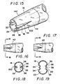
- FIG. 15 is a perspective view of a third embodiment of a deformable nozzle tip according to the present invention.
- FIG. 16 is a side elevational view of the deformable nozzle tip shown in FIG. 15 .
- FIG. 17 is a side elevational view of the deformable nozzle tip shown in FIG. 16 in a substantially deformed configuration.
- FIG. 18 is a cross-sectional view of the deformable nozzle tip shown in FIG. 16 along the line 18 — 18 .
- FIG. 19 is a cross-sectional view of the deformable nozzle tip shown in FIG. 17 in a substantially deformed configuration along the line 19 — 19 .
- FIG. 20 is a side elevational view of a fourth embodiment of a deformable nozzle tip according to the present invention.
- FIG. 21 is a side elevational view of the deformable nozzle tip shown in FIG. 19 in a substantially deformed configuration.
- FIG. 22 is a cross-sectional view of the deformable nozzle tip shown in FIG. 20 along the line 22 — 22 .
- FIG. 23 is a cross-sectional view of the deformable nozzle tip shown in FIG. 21 in a substantially deformed configuration along the line 23 — 23 .
- FIG. 24 is a side elevational view of a fifth embodiment of a deformable nozzle tip according to the present invention.
- FIG. 25 is a cross-sectional view of the deformable nozzle tip shown in FIG. 24 along the line 25 — 25 .
- FIG. 26 is a side elevational view of a sixth embodiment of a deformable nozzle tip according to the present invention.
- FIG. 27 is cross-sectional view of the deformable nozzle tip shown in FIG. 25 along the line 26 — 26 .
- FIG. 28 is a side elevational view of a seventh embodiment of a deformable nozzle tip according to the present invention.
- FIG. 29 is an end view of the nozzle tip shown in FIG. 28 .
- FIG. 30 is an end view of the nozzle tip shown in FIG. 28 in a substantially deformed configuration.
- FIG. 31 is a side elevational view of a eighth embodiment of a deformable nozzle tip according to the present invention.
- FIG. 32 is a side elevational view of the nozzle tip shown in FIG. 31 in a substantially deformed configuration.
- FIG. 33 is a distal end view of the deformable nozzle tip shown in FIG. 31 in a non-deformed configuration.
- FIG. 34 is a distal end view of the deformable nozzle tip shown in FIG. 31 in a substantially deformed configuration.
- FIG. 35 is a partial distal end view of the deformable nozzle tip shown in FIG. 31 .
- FIG. 36 is a side elevational view of an ninth embodiment of a deformable nozzle tip according to the present invention.
- FIG. 37 is a side elevational view of the nozzle tip shown in FIG. 36 in a substantially deformed configuration.
- FIG. 38 is a partial distal end view of the deformable nozzle tip shown in FIG. 36 .
- FIG. 39 is a side elevational view of a tenth embodiment of a deformable nozzle tip according to the present invention.
- FIG. 40 is a side elevational view of the nozzle tip shown in FIG. 39 in a substantially deformed configuration.
- FIG. 41 is a side elevational view of an eleventh embodiment of a deformable nozzle tip according to the present invention.
- FIG. 42 is a side elevational view of the nozzle tip shown in FIG. 41 in a substantially deformed configuration.
- FIG. 43 is a side elevational view of an twelfth embodiment of a deformable nozzle tip according to the present invention.
- FIG. 44 is a side elevational view of the nozzle tip shown in FIG. 43 in a substantially deformed configuration.
- FIG. 45 is a perspective view of a twelfth embodiment of a deformable nozzle tip according to the present invention.
- FIG. 46 is a side elevational view of the nozzle tip shown in FIG. 45 .
- FIG. 47 is a distal end view of the nozzle tip shown in FIG. 45 .
- FIG. 48 is a perspective view of a fourteenth embodiment of a deformable nozzle tip according to the present invention.
- FIG. 49 is a side elevational view of the nozzle tip shown in FIG. 48 .
- FIG. 50 is a distal end view of the nozzle tip shown in FIG. 48 .
- FIG. 51 is a perspective view of a fifteenth embodiment of a deformable nozzle tip according to the present invention.
- FIG. 52 is a side elevational view of the nozzle tip shown in FIG. 51 .
- FIG. 53 is a distal end view of the nozzle tip shown in FIG. 51 .
- FIG. 54 is a perspective view of a sixteenth embodiment of a deformable nozzle tip according to the present invention.
- FIG. 55 is an end view of the nozzle tip shown in FIG. 54 .
- FIG. 56 is a distal end view of the nozzle tip shown in FIG. 54 in a substantially deformed configuration.
- FIG. 57 is a distal end view of an alternative embodiment the wall portion of the nozzle tip shown in FIG. 54 .
- FIG. 58 is a distal view of an alternative embodiment of the wall portion of the nozzle tip shown in FIG. 54 .
- FIG. 59 is a side elevational view of a seventeenth embodiment of a deformable nozzle tip according to the present invention.
- FIG. 60 is a side elevational view of the deformable nozzle tip shown in FIG. 59 in a substantially deformed configuration.
- FIG. 61 is a distal end view of an eighteenth embodiment of a deformable nozzle portion according to the present invention.
- FIG. 62 is a distal end view of the deformable nozzle tip shown in FIG. 61 in a substantially deformed configuration.
- FIG. 63 is a distal end view of an alternative embodiment of the deformable nozzle tip shown in FIG. 61 .
- FIG. 64 is a distal end view of the deformable nozzle portion shown in FIG. 63 in a substantially deformed configuration.
- FIG. 65 is a distal end view of a nineteenth embodiment of a deformable nozzle portion according to the present invention.
- FIG. 66 is a distal end view of the deformable nozzle portion shown in FIG. 65 in a substantially expanded configuration.
- FIG. 67 is a distal end view of the nozzle portion shown in FIG. 65 in a substantially non-deformed configuration.
- FIG. 68 is a perspective view of a twentieth embodiment of a deformable nozzle tip according to the present invention.
- FIG. 69 is a distal end view of the deformable nozzle tip shown in FIG. 68 .
- FIG. 70 is a distal end view of the deformable nozzle tip shown in FIG. 69 in a substantially deformed configuration.
- FIG. 71 is a partial distal end view of the deformable nozzle tip shown in FIG. 68 .
- FIG. 72 is a partial distal end view of an alternative embodiment of the deformable nozzle tip shown in FIG. 68 .
- FIG. 73 is a perspective view of a twenty-first embodiment of a nozzle tip according to the present invention.
- FIG. 74 is a distal end view of the deformable nozzle tip shown in FIG. 73 .
- FIG. 75 is a distal end view of the deformable nozzle tip shown in FIG. 73 in a substantially deformed configuration.
- FIG. 76 is a perspective view of a twenty-second embodiment of a deformable nozzle tip according to the present invention.
- FIG. 77 is a distal end view of the of the deformable nozzle tip shown in FIG. 75 .
- FIG. 78 is a distal end view of the of the deformable nozzle tip shown in FIG. 76 in a substantially deformed configuration.
- FIG. 79 is a perspective view of a twenty-third embodiment of a deformable nozzle tip according to the present invention.
- FIG. 80 is a side elevational view of the nozzle tip shown in FIG. 79 .
- FIG. 81 is a distal end view of the nozzle tip shown in FIG. 79 .
- FIG. 82 is a side elevational view of the nozzle tip shown in FIG. 79 in a substantially deformed configuration.
- FIG. 83 is a perspective view of a twenty-fourth embodiment of a deformable nozzle tip according to the present invention.
- FIG. 84 is a distal end view of the deformable nozzle tip shown in FIG. 83 .
- FIG. 85 is a perspective view of a twenty-fifth embodiment of a deformable nozzle tip according to the present invention.
- FIG. 86 is a distal end view of the deformable nozzle tip shown in FIG. 85 .
- FIG. 87 is a perspective view of a twenty-sixth embodiment of a deformable nozzle tip according to the present invention.
- FIG. 88 is a distal end view of the deformable nozzle tip shown in FIG. 87 .
- FIG. 89 is a perspective view of a twenty-seventh embodiment of a deformable nozzle tip according to the present invention.
- FIG. 90 is a distal end view of the deformable nozzle tip shown in FIG. 89 .
- FIG. 91 is a side elevational view of the deformable nozzle portion shown in FIG. 90 in a substantially deformed configuration.
- FIG. 92 is a perspective view of a twenty-eighth embodiment of a deformable nozzle tip according to the present invention.
- FIG. 93 is a distal end view of the nozzle tip shown in FIG. 92 in a substantially compressed configuration.
- FIG. 94 is a distal end view of the nozzle tip shown in FIG. 93 .
- FIG. 95 is a distal end view of the nozzle tip shown in FIG. 94 in a partially deformed configuration.
- FIG. 96 is a distal end view of the nozzle tip shown in FIG. 92 in a substantially deformed configuration.
- FIG. 97 is a perspective view of an alternative embodiment of the deformable nozzle tip shown in FIG. 92 .
- FIG. 98 is a distal end view of the nozzle tip shown in FIG. 97 .
- FIG. 99 is a distal end view of the nozzle tip shown in FIG. 97 in a partially deformed configuration.
- FIG. 100 is a distal end view of the nozzle tip shown in FIG. 97 in a substantially deformed configuration.
- FIG. 101 is a distal end view of a twenty-ninth embodiment of a deformable nozzle tip according to the present invention.
- FIG. 102 is a distal end view of the deformable nozzle tip shown in FIG. 99 in a partially deformed configuration.
- FIG. 103 is a distal end view of the deformed nozzle tip shown in FIG. 99 is a substantially deformed configuration.
- the present invention is directed to devices for implanting a deformable intraocular lens structure within the eye.
- FIGS. 1 and 2 A preferred embodiment of a deformable intraocular lens implantation device 210 according to the present invention is shown in FIGS. 1 and 2.
- the implantation device comprises a microcartridge 212 disposed within a holder 213 comprising a holder body 214 with a receiver 215 , and a moveable plunger 216 .
- Moveable plunger 216 is fitted with an end cap 218 at a proximal end, and fitted with a plunger tip 220 at a distal end.
- the end cap 218 is provided with a concave end face 222 to allow a person to securely engage end cap 218 with his or her finger tip or tips.
- the plunger 216 is installed within the holder 213 in a manner to allow the plunger to be reciprocated therein. In the illustrated embodiment, the plunger 216 is supported for sliding movement within the holder 213 by guide 226 .
- microcartridge 212 includes a lens receiving portion 224 , an extending portion 228 , a nozzle portion 16 and a deformable nozzle tip 14 .
- Lens receiving portion 224 and nozzle portion 16 of microcartridge 212 define a lens delivery passageway portion 230 which communicates with a nozzle tip lens delivery passageway portion 22 through deformable nozzle tip portion 14 .
- Plunger tip 220 is configured to advance a deformable intraocular lens (not shown) through lens delivery passageway portion 230 and nozzle tip lens delivery passageway portion 22 .
- a deformable intraocular lens is loaded into the proximal end of lens receiving portion 224 of microcartridge 212 which is pre-lubricated with a surgically compatible lubricant.
- Moveable plunger 216 is moved into a retracted proximal position and microcartridge 212 is loaded into receiver 215 .
- receiver 215 is configured to engage extending portion 228 and thereby prevent rotational and axial distal movement of the loaded microcartridge 212 .
- Moveable plunger 216 is then moved distally relative to the holder 213 until plunger tip 220 contacts the loaded deformable intraocular lens.
- Deformable nozzle tip 14 and a portion of nozzle portion 16 of microcartridge 212 are then placed at and guided through an ocular incision.
- the moveable plunger 216 is then further moved distally relative to the holder 213 to advance plunger tip 220 and thus, the deformable intraocular lens, through lens delivery passageway portion 230 and nozzle tip lens delivery passageway portion 22 into the eye.
- Plunger tip 220 may be used to position the intraocular lens within the eye.
- FIG. 3 An alternative embodiment of a deformable intraocular lens implantation device 210 ′ according to the present invention is shown in FIG. 3 .
- the implantation device 210 ′ comprises a holder 213 ′ including a holder body 214 ′ and an integrated cartridge portion 232 ′, and a moveable plunger 216 ′.
- Moveable plunger 216 ′ is fitted with an end cap 218 ′ at one end, and fitted with a plunger tip 220 ′ at an opposite end.
- the end cap 218 ′ is provided with a concave end face 222 ′ to allow a person to securely engage end cap 218 ′ with his or her finger tip or tips.
- the plunger 216 ′ is installed within the holder 213 ′ in a manner to allow the plunger to be reciprocated therein. In the illustrated embodiment, the plunger 216 ′ is supported for sliding movement within the holder 213 ′ by guide 226 ′.
- Integrated cartridge portion 232 ′ comprises a lens receiving port 234 ′, a nozzle portion 16 ′ and a deformable nozzle tip portion 14 ′.
- Integrated cartridge portion 232 ′ also defines a lens delivery passageway portion 230 ′ which communicates proximally with lens receiving port 234 ′ and distally with nozzle tip lens delivery passageway portion 22 ′ through deformable nozzle tip portion 14 ′.
- Plunger tip 220 ′ is configured to engage a deformable intraocular lens (not shown) in lens receiving port 234 ′ and advance the lens through lens delivery passageway portion 230 ′ and nozzle tip lens delivery passageway portion 22 ′.
- moveable plunger 216 ′ is moved into a retracted proximal position and lens receiving port 234 ′ is lubricated with a surgically compatible lubricant.
- a deformable intraocular lens is then loaded into lens receiving port 234 ′.
- Moveable plunger 216 ′ is then moved distally relative to the holder 213 ′ until plunger tip 220 ′ engages the loaded deformable intraocular lens.
- Deformable nozzle tip 14 ′ and a portion of nozzle portion 16 ′ of integrated cartridge portion 232 ′ are then placed at and guided through an ocular incision.
- the moveable plunger 216 ′ is then further moved distally relative to the holder 213 ′ to advance plunger tip 220 ′ and thus, the deformable intraocular lens, through lens delivery passageway portion 230 ′ and nozzle tip lens delivery passageway portion 22 ′ into the eye.
- Plunger tip 220 ′ may be used to position the intraocular lens within the eye.
- Deformable nozzle tip 14 and a partial section of nozzle portion 16 are shown in FIGS. 4-8.
- Deformable nozzle tip 14 includes a continuous wall portion 18 which extends in a distal direction from the nozzle portion 16 and defines a distally tapering nozzle tip lens delivery passageway portion 22 having an entrance 24 and an exit 26 .
- Nozzle tip lens delivery passageway portion 22 communicates with lens delivery passageway 230 of the deformable intraocular lens implanting device 210 .
- Continuous wall portion 18 may vary in thickness.
- deformable nozzle tip portion may be defined by a distal portion of nozzle portion 18 having a conical lens delivery passageway portion.
- Each hinge 32 includes two (2) substantially planar hinge portions 34 .
- hinges 32 are integral with wall portion 18 and may have a reduced wall thickness.
- each hinge 32 shown in FIGS. 4-8 defines two (2) base joints 36 and one peak joint 38 .
- the base joints 36 and peak joint 38 of each hinge 32 extend linearly and distally from a convergence point 42 within wall portion 18 .
- the width, W, of each hinge portion 34 increases towards the distal end of deformable nozzle tip portion 14 .
- each peak joint 38 extends distally towards the longitudinal axis of nozzle tip lens delivery passageway portion 22 at an angle, A, which in the preferred embodiment shown in FIGS. 4-9, is greater than the angle of taper, T, of wall portion 18 , shown in FIG. 5 .
- the deformable nozzle tip 14 is guided, in the non-deformed configuration shown in FIGS. 4, 5 and 8 , through a small incision in the ocular tissue so that the exit 26 of the nozzle tip lens delivery passageway portion 22 is properly oriented in the capsule of the eye.
- the substantially circular shaped and reduced transverse cross-sectional profile of wall portion 18 at exit 26 provides a deformable nozzle tip portion 14 which is easily placed at an ocular incision.
- a nozzle tip according to the present invention may compress as it is guided through an ocular incision as shown in FIG. 7 . It is contemplated to provide hinge portions 34 which extend beyond exit 24 and which define a sharp point and/or edges for use in surgically incising the ocular tissue.
- a deformable intraocular lens is advanced into nozzle tip lens delivery passageway portion 22 .
- the lens exerts a radially outwardly directed force against the tapering wall portion 18 of deformable nozzle tip 14 .
- the reactive force against the lens may cause the lens to deform, or, in embodiments of device 102 where the lens is already deformed, to deform further.
- the force of the lens against the wall portion 18 causes the angle between the base joints 36 of each hinge to increase, and consequently, the distance between the peak joint 38 and the plane defined by base joints 36 of each hinge 32 to decrease.
- the force causes an initial deformation of the transverse cross-sectional profile of wall portion 18 .
- this initial deformation causes the hinges 32 to become substantially more smooth prior to there being any contact between the advancing lens and hinges 26 thus providing for a deformable lens delivery procedure which is more protective of the integrity of the deformable lens.
- the thickness of the material which defines base joints 36 and peak joints 38 may be decreased.
- base joints 32 and/or peak joints 38 of deformable nozzle portion 14 may be perforated or otherwise made more flexible.
- the lens As the lens is advanced further through the nozzle tip lens delivery passageway portion 22 , the lens continues to exert a radially outwardly directed force against wall portion 18 .
- the lens also contacts hinges 32 , and in particular, the peak joints 38 thereof.
- the initial deformation of the deformable nozzle tip 14 relaxes the angle at which peak joints 38 extend from convergence points 42 toward the longitudinal axis of nozzle tip lens delivery passageway portion 22 . This allows the lens to more easily slide past hinges 32 , and in particular, past peak joints 38 .
- peak joints 38 may be rounded.
- the force of the lens against the hinges 32 causes the transverse cross-sectional profile of wall portion 18 to deform further.
- the deformation of wall portion 18 results in an increase in the transverse cross-sectional area of nozzle tip lens delivery passageway portion 22 .
- the transverse cross-sectional profile of nozzle tip lens delivery passageway portion becomes elongated as shown in FIG. 9 .
- wall portion 18 The limit of deformation of wall portion 18 is reached when the peak joint 36 of each hinge 32 is substantially coincident with the plane defined by the base joints 34 of the respective hinge 32 . Note that for the deformable nozzle tip 14 shown in FIGS. 4-9, the maximum possible transverse cross-sectional area of nozzle tip lens delivery passageway portion 22 occurs at the exit 26 thereof.
- deforming nozzle tip portion 14 allows the lens to return to a non-deformed configuration (i.e. to expand thereby reducing the energy stored therein).
- the lens may be partially or fully returned from a deformed configuration upon ejection from exit 26 . Because the elastic stresses set up in the lens by the deformation procedure are substantially relieved prior to the introduction of the lens into the eye, there is less chance of injury to the eye than if the lens were simply allowed to “spring” back or rapidly return from a deformed configuration to its pre-deformed configuration within the eye. Such “springing” could, for example, damage the capsular bag. There is also less chance of damage occurring to the lens or the lens becoming improperly orientated within the eye. In short, the implantation procedure is improved.
- deformable nozzle tip 14 After implantation of the lens in the eye, deformable nozzle tip 14 substantially returns to the non-deformed configuration shown in FIGS. 4, 5 and 8 .
- the deformable nozzle tip 14 may be compressed, as shown in FIG. 7, during withdrawal by surrounding tissue or may be compressed by the transmission of a compressive force on the nozzle portion 16 as, for example, by forceps or the hand of a surgeon at nozzle portion 16 for easily withdrawal from the eye.
- Hinges 32 may be configured to bias deformable nozzle tip 14 towards a non-deformed configuration.
- hinge portions 34 may be either convex or concave.
- Deformable nozzle tip 14 may be configured to temporarily remain in the deformed configuration shown in FIGS. 6 and 9 after ejection of the lens therefrom. By configuring nozzle tip 14 to temporarily remain in a substantially deformed configuration after lens ejection, the nozzle tip 14 is prevented from exerting a distally oriented force on the intraocular lens. In other words, the deformable nozzle tip 14 is prevented from “squirting” the lens into the eye.
- deformable nozzle tip portion 14 may be constructed of materials which resume a pre-deformed shape slowly, for example, materials having prescribed memory characteristics.
- deformable nozzle tip portion 14 may be configured to return to a non-deformed configuration by the force of surrounding tissue against wall portion 18 as the nozzle tip 14 is removed from the eye.
- FIGS. 10-14 A second embodiment of a deformable nozzle tip portion 141 is shown in FIGS. 10-14.
- Wall portion 18 of deformable nozzle tip 141 includes hinges 32 along the entire perimeter thereof. As shown in FIGS. 13-14, the transverse cross-sectional profile of wall portion 18 tends to deform uniformly about the longitudinal axis of the nozzle tip lens delivery passageway portion 22 as the lens advances through the nozzle tip portion lens delivery passageway 22 .
- FIGS. 15-19 A third embodiment of a deformable nozzle tip portion 142 is shown in FIGS. 15-19.
- Wall portion 18 of deformable nozzle tip 142 includes a pair of diametrically opposed hinges 322 .
- each hinge 322 is made of four (4) hinge portions 34 which define three (3) peak joints 38 and two base joints 36 .
- Peak joints 38 and base joints 36 of each hinge 322 extend from a common point 42 within wall portion 18 of deformable nozzle tip portion 141 . Note from a comparison of FIGS. 9 and 19 that by increasing the number of hinge portions within hinge 32 ( 322 ), the extent to which the transverse cross-sectional profile of wall portion 18 elongates is also increased.
- FIGS. 20-23 A fourth embodiment of a deformable nozzle tip portion 143 is shown in FIGS. 20-23.
- Wall portion 18 includes four hinges 323 .
- Curvilinear base joints 363 and linear peak joint 383 of each hinge 323 extend from convergence point 42 within wall portion 18 .
- the distal portions of base joints 363 of each hinge 323 are substantially parallel.
- FIGS. 24 and 25 A fifth embodiment of a deformable nozzle tip portion 144 is shown in FIGS. 24 and 25.
- hinges 32 may be included in a wall portion 184 which does not taper.
- hinges 32 may also be included in a wall portion 184 having an exit 264 which defines a plane, the normal of which is not coincident with, but rather, defines an angle relative to, the longitudinal axis of the nozzle tip lens delivery passageway 22 .
- hinges 32 may also be included in a wall portion 185 which tapers and which has an exit 265 which defines a plane, the normal of which is at an angle relative to the longitudinal axis of the nozzle tip lens delivery passageway portion 22 .
- FIGS. 28-30 A seventh embodiment of a deformable nozzle tip portion 1414 is shown in FIGS. 28-30.
- the transverse cross-sectional profile of wall portion 18 is substantially square shaped and defines a tapering nozzle tip lens delivery passageway portion 22 . Note from FIGS. 28-30 that corners 62 remain stationary during deformation of the transverse cross-sectional profile of wall portion 18 .
- FIGS. 31-35 An eighth embodiment of a deformable nozzle tip portion 146 is shown in FIGS. 31-35.
- wall portion 18 of nozzle tip portion 146 includes a pair of diametrically opposed expansion zones 46 .
- expansion zones 46 are substantially triangular shaped regions of reduced wall thickness within wall portion 18 .
- Expansion zones 46 are preferably configured to undergo elastic and/or plastic deformation as a deformable lens is advanced through the nozzle tip lens delivery passageway portion 22 thereby allowing for the transverse cross-sectional profile of wall portion 18 to deform.
- FIGS. 36-41 A ninth embodiment of a deformable nozzle tip portion 147 including a pair of diametrically opposed expansion zones 461 is shown in FIGS. 36-41.
- expansion zones 461 are regions of reduced wall thickness within wall portion 18 which are configured to fail, preferably by tearing at a predetermined location 48 within each expansion zone 461 , as a lens is advanced through nozzle tip lens delivery passageway portion 22 .
- Expansion zones 461 may be configured to undergo elastic and/or plastic deformation prior to failing.
- FIGS. 36-38 A tenth embodiment of a non-tapering deformable nozzle tip portion 148 including a pair of substantially rectangular shaped expansion zones 462 is shown in FIGS. 36-38.
- an expansion zone 463 is coextensive with a slot 48 in wall portion 18 .
- the slot 48 shown in FIGS. 41-42 extends from the exit 26 of nozzle tip lens delivery passageway 22 to the curved distal edge of expansion zone 463 .
- a twelfth embodiment of a deformable nozzle tip portion 1410 shown in FIGS. 43-44 includes independent slots 481 and expansion zones 464 in wall portion 18 .
- expansion zones 46 may be regions within wall portion 18 which have been weakened chemically, for example, etched, or mechanically, for example, pre-stretched. Further, expansion zones 46 may have the same wall thickness as the rest of wall portion 18 .
- FIGS. 45-47 A thirteenth embodiment of a deformable nozzle tip portion 1411 is shown in FIGS. 45-47.
- Wall portion 18 defines a contiguous flap 54 and an optional longitudinal groove 52 .
- flap 52 As a deformable lens is advanced through nozzle tip lens delivery passageway 22 , a portion of the lens engages groove 52 which guides the deformable intraocular lens into contact with flap 54 .
- the advancing lens causes flap 52 to pivot resulting in a deformation of the transverse cross-sectional profile of wall portion 18 .
- flap 52 dampens the return of the lens to a non-deformed configuration as the lens advances through angled exit 26 of the nozzle tip lens delivery passageway portion 22 .
- the lens is thereby prevented from “springing” out of deformable nozzle tip portion 1411 .
- FIGS. 48-50 A fourteenth embodiment of a deformable nozzle tip portion 1412 is shown in FIGS. 48-50.
- Wall portion 18 of nozzle tip portion 1412 defines distally extending flexible petals 76 .
- the substantially hemispherical shaped nozzle tip portion 1412 provides a substantially closed exit 26 which is more easily placed at and guided through an ocular incision.
- flexible petals open outwardly resulting in a deformation of the transverse cross sectional profile of wall portion 18 .
- FIGS. 51-53 A fifteenth embodiment of a deformable nozzle tip portion 1413 is shown in FIGS. 51-53.
- Wall portion 18 includes semi-rigid fingers 58 which extend longitudinally along the corners 62 of the nozzle tip lens delivery passageway portion 22 .
- Semi-rigid fingers 58 prevent nozzle tip lens delivery passageway portion 22 of deformable nozzle tip 1413 from excessively deflecting from the longitudinal axis of the nozzle lens delivery passageway 102 of nozzle portion 16 .
- FIGS. 54-56 A sixteenth embodiment of a deformable nozzle tip portion 1415 is shown in FIGS. 54-56.
- Wall portion 18 defines a proximal tapering nozzle tip lens delivery passageway portion 2211 and a distal nozzle tip lens delivery passageway portion 2212 .
- the transverse cross-sectional profile of wall portion 18 along proximal tapering nozzle tip lens delivery passageway portion 2211 is rigid and non-deforming.
- the substantially rectangular shaped transverse cross-sectional profile of wall portion 18 along distal nozzle tip lens delivery passageway portion 2212 deforms as shown in FIG. 56 .
- the thickness of wall portion 18 along proximal nozzle tip lens delivery passageway portion 2212 may be varied to alter the manner in which the transverse cross-sectional profile of wall portion 18 along proximal nozzle tip lens delivery passageway portion 2212 deforms.
- the short sides of the substantially rectangular shaped transverse cross-sectional profile of wall portion 18 ′ along the distal nozzle tip lens delivery passageway portion 2212 shown in FIG. 57 are thicker than the long sides thereof.
- the long sides of the substantially rectangular shaped transverse cross-sectional profile of wall portion 18 ′′ along the distal nozzle tip lens delivery passageway portion 2212 shown in FIG. 58 are thicker than the short sides thereof.
- FIGS. 59-60 A seventeenth embodiment of a deformable nozzle tip portion 1416 is shown in FIGS. 59-60.
- the transverse cross-sectional profile of wall portion 18 is substantially tubular and elastic. As shown in FIG. 59, the transverse cross-sectional profile of wall portion 18 conforms to the profile of the advancing intraocular lens.
- FIGS. 61-62 An eighteenth embodiment of a deformable nozzle tip portion 1417 is shown in FIGS. 61-62.
- the substantially crescent shaped transverse cross-sectional profile of wall portion 18 defines a first arcuate portion 64 having a greater radius of curvature than a second arcuate portion 66 thereof.
- the transverse cross-sectional profile of wall portion 18 deforms as shown in FIG. 62 . It is important to recognize that both first and second arcuate portions 64 and 66 bias against the radially outward deformation of second arcuate portion 66 .
- Slots 72 in deformable nozzle tip 1417 ′ shown in FIGS. 63 and 64 decrease the force necessary to deform second arcuate portion 66 .
- FIGS. 65-67 A nineteenth embodiment of a deformable nozzle tip portion 1418 is shown in FIGS. 65-67.
- the transverse cross-sectional profile of wall portion 18 defines an arcuate portion 74 , a first arm portion 76 and a second arm portion 78 .
- first and second arm portions 76 , 78 are of an equal length which is greater than the radius of curvature of arcuate portion 74 .
- first and second arm portions 76 , 78 may have different lengths as long as the combined total length of first and second arm portions 76 , 78 is greater than double the radius of curvature of arcuate portion 74 .
- first and second arm portions 76 , 78 deflect away from arcuate portion 74 .
- the deflection of arms 76 , 78 causes a stress to be induced in arcuate portion 74 .
- the stress in arcuate portion 74 biases arms 76 , 78 to the configuration shown in FIG. 64 .
- the stress in arcuate portion 74 reaches a maximum when deflecting arms 76 , 78 define a straight line path between the ends of arcuate portion 74 .
- FIGS. 68-72 A twentieth embodiment of a deformable nozzle tip 1419 is shown in FIGS. 68-72.
- Wall portion 18 includes four (4) expansion assemblies 84 .
- Expansion assemblies 84 are sections of wall portion 18 which deflect without creating substantial stress in adjacent sections of wall portion 18 .
- the transverse cross sectional profile of wall portion 18 deforms as shown in FIGS. 71-72.
- each expansion assembly 84 is preferably a section of wall portion 18 which has been rendered substantially weak by, for example, the removal of material therefrom.
- an expansion assembly 84 ′ shown in FIG. 72, may be created in wall portion 18 by continuous plastic deformation of a section of wall portion 18 .
- FIGS. 73-75 A twenty-first embodiment of a deformable nozzle tip 1420 is shown in FIGS. 73-75.
- Wall portion 18 includes an overlap portion 86 .
- the force of the lens against wall portion 18 causes the inner surface of overlap portion 86 of wall portion 18 to slide over the adjacent outer surface of wall portion 18 .
- the transverse cross-sectional profile of wall portion 18 is thereby deformed.
- a barb and catch assembly (not shown) may be included therebetween.
- FIGS. 76-78 A twenty-second embodiment of a deformable nozzle tip 1421 is shown in FIGS. 76-78.
- the transverse cross-sectional profile of wall portion 18 is substantially square shaped. Further, the thickness of wall portion 18 at corners 88 and 88 ′ is substantially less than along the sides 92 thereof.
- sides 92 are forced to pivot about corners 88 and 88 ′. For example, as shown in FIG. 78, corners 88 ′ are forced farther apart and corners 88 are forced closer together.
- the increased dimension of the transverse cross-sectional profile of wall portion 18 defined by the distance between corners 88 ′ allows the deformed intraocular lens to release a portion of the stress associated with lens deformation.
- FIGS. 79-81 A twenty-third embodiment of a deformable nozzle tip 1422 is shown in FIGS. 79-81.
- Wall portion 18 includes a first jaw 94 , a second jaw 96 , and diametrically opposed slots 98 .
- first and second jaws 96 and 98 pivot and thereby cause the transverse cross-sectional profile of wall portion 18 to deform.
- slots 98 are of sufficient size to prevent nozzle portion 16 from collapsing or otherwise deforming during pivoting of first and second jaw portions 96 and 98 , respectively.
- FIGS. 83-84 A twenty-fourth embodiment of a deformable nozzle tip 1423 is shown in FIGS. 83-84. As shown in FIG. 84, the transverse cross-sectional profile of wall portion 18 defines a first arcuate portion 102 having a slot 106 and a second arcuate portion 104 .
- FIGS. 85-86 A twenty-fifth embodiment of a deformable nozzle tip 1424 is shown in FIGS. 85-86. As shown in FIG. 86, the transverse cross-sectional profile of wall portion 18 defines a first arcuate portion 102 ′ having a slot 106 ′ and a second arcuate portion 104 ′ having a slot 106 ′′.
- FIGS. 87-88 A twenty-sixth embodiment of a deformable nozzle tip 1425 is shown in FIGS. 87-88.
- the transverse cross-sectional profile of wall portion 18 defines an outer portion including a first arcuate portion 108 and a second arcuate portion 112 .
- First and second arcuate portions 108 and 112 are separated by opposed outer portion slots 114 .
- the transverse cross-sectional profile of wall portion 18 also defines an inner portion including a first jaw portion 116 and a second jaw portion 118 .
- First and second jaw portions 116 and 118 are separated by opposed inner portion slots 122 .
- inner portion slots 122 are in perpendicular relation to outer portion slots 114 .
- deformable nozzle tip 1425 prevents an advancing lens from escaping nozzle portion lens delivery passageway 22 .
- outer portion arcuate portions 108 and 112 respectively, provide bias against the outward deflection of inner portion jaw portions, 116 and 118 , respectively.
- FIGS. 89-91 A twenty-seventh embodiment of a deformable nozzle tip 1426 is shown in FIGS. 89-91.
- the transverse cross-sectional profile of wall portion 18 defines a first arcuate portion 124 and a second arcuate portion 126 .
- First and second arcuate portions 124 and 126 are separated by opposing slots 128 .
- wall portion 18 also includes a pair of opposing longitudinal plunger tip engaging ramp portions 132 . Note that ramp portions 132 terminate substantially proximally of exit 26 of nozzle tip lens delivery passageway portion 22 . As shown in FIG.
- plunger tip 202 engages ramps 132 and thereby outwardly deflects first and second arcuate portions 124 and 126 , respectively. It is important to recognize that plunger tip 202 deforms the transverse cross-sectional profile of wall portion 18 . Also, note that plunger tip 202 engages ramps 132 before the deformable lens (not shown) passes through exit 26 of nozzle tip lens delivery passageway portion 22 . Thus, stresses in the lens associated with deformation are substantially relieved from the lens prior to the lens entering the eye.
- longitudinal channels terminating proximally of the exit 26 of nozzle tip lens delivery passageway 22 may be provided in wall portion 18 .
- a plunger tip including radial protrusions for engaging the channels in wall portion 18 may be provided. As the plunger tip advances past the termination point of the channels in wall portion 18 , the plunger tip protrusions will cause the transverse cross-sectional profile of wall portion 18 to deform.
- FIGS. 92-96 A twenty-eighth embodiment of a deformable nozzle tip 1427 is shown in FIGS. 92-96.
- the transverse cross sectional profile of wall portion 18 preferably defines a set of four (4) spoke portions, each including a bias corner portion 134 and side portions 136 .
- the wall thickness of wall portion 18 between side portions 136 of adjacent spoke portions is preferably a reduced thickness portion 138 for reducing the amount of force necessary to deform the transverse cross-sectional profile of wall portion 18 .
- FIGS. 101-103 A twenty-ninth embodiment of a deformable nozzle tip 1428 is shown in FIGS. 101-103.
- the transverse cross-sectional profile of wall portion 18 includes pleats 142 .
- the transverse cross-sectional profile of wall portion 18 deforms as shown in FIGS. 103-104.
- Pleats 142 bias the transverse cross-sectional profile of wall portion 18 to the non-deformed configuration shown in FIG. 102 .
Abstract
Description
Claims (20)
Priority Applications (1)
| Application Number | Priority Date | Filing Date | Title |
|---|---|---|---|
| US09/562,762 US6629979B1 (en) | 1992-09-30 | 2000-05-02 | Implantation device with deformable nozzle tip for implanting a deformable intraocular lens |
Applications Claiming Priority (16)
| Application Number | Priority Date | Filing Date | Title |
|---|---|---|---|
| US95325192A | 1992-09-30 | 1992-09-30 | |
| US19571794A | 1994-02-14 | 1994-02-14 | |
| US08/196,855 US5941886A (en) | 1992-09-30 | 1994-02-15 | Hingeless lens cartridges for insertion of deformable intraocular lens |
| US22099994A | 1994-04-01 | 1994-04-01 | |
| US24052094A | 1994-07-19 | 1994-07-19 | |
| US34536094A | 1994-11-18 | 1994-11-18 | |
| US36879295A | 1995-01-04 | 1995-01-04 | |
| US08/401,523 US5807400A (en) | 1992-09-30 | 1995-03-10 | Deformable intraocular lens insertion system |
| US40353095A | 1995-03-14 | 1995-03-14 | |
| US44910395A | 1995-05-24 | 1995-05-24 | |
| US08/547,908 US5616148A (en) | 1992-09-30 | 1995-10-25 | Transverse hinged deformable intraocular lens injecting apparatus |
| US08/547,295 US5620450A (en) | 1992-09-30 | 1995-10-25 | Transverse hinged deformable intraocular lens injecting apparatus |
| US08/570,564 US5772666A (en) | 1992-09-30 | 1995-12-11 | Deformable intraocular lens injecting apparatus with deformable tip plunger |
| US64943396A | 1996-05-17 | 1996-05-17 | |
| US08/808,576 US6056757A (en) | 1992-09-30 | 1997-02-28 | Implantation device with deformable nozzle tip for implanting a deformable intraocular lens |
| US09/562,762 US6629979B1 (en) | 1992-09-30 | 2000-05-02 | Implantation device with deformable nozzle tip for implanting a deformable intraocular lens |
Related Parent Applications (1)
| Application Number | Title | Priority Date | Filing Date |
|---|---|---|---|
| US08/808,576 Continuation US6056757A (en) | 1992-09-30 | 1997-02-28 | Implantation device with deformable nozzle tip for implanting a deformable intraocular lens |
Publications (1)
| Publication Number | Publication Date |
|---|---|
| US6629979B1 true US6629979B1 (en) | 2003-10-07 |
Family
ID=25199160
Family Applications (2)
| Application Number | Title | Priority Date | Filing Date |
|---|---|---|---|
| US08/808,576 Expired - Lifetime US6056757A (en) | 1992-09-30 | 1997-02-28 | Implantation device with deformable nozzle tip for implanting a deformable intraocular lens |
| US09/562,762 Expired - Lifetime US6629979B1 (en) | 1992-09-30 | 2000-05-02 | Implantation device with deformable nozzle tip for implanting a deformable intraocular lens |
Family Applications Before (1)
| Application Number | Title | Priority Date | Filing Date |
|---|---|---|---|
| US08/808,576 Expired - Lifetime US6056757A (en) | 1992-09-30 | 1997-02-28 | Implantation device with deformable nozzle tip for implanting a deformable intraocular lens |
Country Status (9)
| Country | Link |
|---|---|
| US (2) | US6056757A (en) |
| EP (1) | EP1011536A2 (en) |
| JP (1) | JP4020439B2 (en) |
| KR (1) | KR20000075691A (en) |
| CN (1) | CN1250362A (en) |
| AU (1) | AU736178B2 (en) |
| CA (1) | CA2281652A1 (en) |
| NZ (1) | NZ337057A (en) |
| WO (1) | WO1998037830A2 (en) |
Cited By (50)
| Publication number | Priority date | Publication date | Assignee | Title |
|---|---|---|---|---|
| US20060229634A1 (en) * | 2005-04-08 | 2006-10-12 | Shepherd David J | Methods and apparatus for inserting an intraocular lens into an eye |
| US20060229633A1 (en) * | 2005-04-08 | 2006-10-12 | Shepherd David J | Methods and apparatus for inserting an intraocular lens into an eye |
| US20060235430A1 (en) * | 2005-04-15 | 2006-10-19 | Intralens Vision, Inc. | Corneal implant injector assembly and methods of use |
| WO2008023148A1 (en) * | 2006-08-19 | 2008-02-28 | Barry Vic Oliver | Nozzle for application of flowable building material |
| US20080147082A1 (en) * | 2006-12-13 | 2008-06-19 | Joel Pynson | Injector apparatus for use with intraocular lenses and methods of use |
| US20080147081A1 (en) * | 2006-12-13 | 2008-06-19 | Joel Pynson | Intraocular lens injector apparatus and methods of use |
| US7455691B2 (en) | 2004-11-03 | 2008-11-25 | Biovision, Ag | Intraocular and intracorneal refractive lenses |
| US20090099536A1 (en) * | 2006-11-06 | 2009-04-16 | Takayuki Akahoshi Akahoshi | Bidirectional Phacoemulsification Needle Tips for Torsional and Longitudinal Motion |
| US20090292294A1 (en) * | 2006-08-11 | 2009-11-26 | Kowa Company, Ltd. | Intraocular lens insertion tool |
| WO2010068608A2 (en) * | 2008-12-11 | 2010-06-17 | Bausch & Lomb Incorporated | Intraocular lens and method of making an intraocular lens |
| US7776086B2 (en) | 2004-04-30 | 2010-08-17 | Revision Optics, Inc. | Aspherical corneal implant |
| US7901414B2 (en) | 2001-12-12 | 2011-03-08 | Ioltechnologie-Production | Cassette and injector for flexible intraocular lens and method for injecting such lenses |
| US8057541B2 (en) | 2006-02-24 | 2011-11-15 | Revision Optics, Inc. | Method of using small diameter intracorneal inlays to treat visual impairment |
| US8162953B2 (en) | 2007-03-28 | 2012-04-24 | Revision Optics, Inc. | Insertion system for corneal implants |
| US8382769B2 (en) | 2008-06-17 | 2013-02-26 | Hoya Corporation | Intraocular lens insertion device |
| US8460311B2 (en) | 2004-12-27 | 2013-06-11 | Hoya Corporation | Intraocular lens implanting device |
| US8470032B2 (en) | 2008-09-04 | 2013-06-25 | Hoya Corporation | Intraocular lens insertion device |
| US8469948B2 (en) | 2010-08-23 | 2013-06-25 | Revision Optics, Inc. | Methods and devices for forming corneal channels |
| US8475528B2 (en) | 2007-05-30 | 2013-07-02 | Hoya Corporation | Intraocular lens insertion device |
| US8523941B2 (en) | 2005-12-08 | 2013-09-03 | Hoya Corporation | Instrument for inserting intraocular lens |
| US8523877B2 (en) | 2005-02-24 | 2013-09-03 | Hoya Corporation | Intraocular lens inserting instrument |
| US8545512B2 (en) | 2005-01-26 | 2013-10-01 | Hoya Corporation | Intraocular lens insertion device |
| US8574239B2 (en) | 2005-09-28 | 2013-11-05 | Hoya Corporation | Intraocular lens insertion device |
| US8603103B2 (en) | 2009-01-07 | 2013-12-10 | Hoya Corporation | Intraocular lens insertion device |
| US8647382B2 (en) | 2010-06-10 | 2014-02-11 | Hoya Corporation | Ocular implant insertion apparatus and methods |
| US8668735B2 (en) | 2000-09-12 | 2014-03-11 | Revision Optics, Inc. | Corneal implant storage and delivery devices |
| US8702795B2 (en) | 2008-08-21 | 2014-04-22 | Hoya Corporation | Intraocular lens inserting device |
| US8747465B2 (en) | 2007-05-30 | 2014-06-10 | Hoya Corporation | Intraocular lens insertion device |
| US8900296B2 (en) | 2007-04-20 | 2014-12-02 | Revision Optics, Inc. | Corneal inlay design and methods of correcting vision |
| US8998983B2 (en) | 2012-06-04 | 2015-04-07 | Altaviz, Llc | Intraocular lens inserters |
| US9005280B2 (en) | 2000-09-12 | 2015-04-14 | Revision Optics, Inc. | System for packaging and handling an implant and method of use |
| US9114006B2 (en) | 2007-07-11 | 2015-08-25 | Hoya Corporation | Intraocular lens insertion device and method for controlling movement of the intraocular lens |
| US9271828B2 (en) | 2007-03-28 | 2016-03-01 | Revision Optics, Inc. | Corneal implant retaining devices and methods of use |
| US9326847B2 (en) | 2010-04-08 | 2016-05-03 | Hoya Corporation | Ocular implant insertion apparatus and methods |
| US9345569B2 (en) | 2011-10-21 | 2016-05-24 | Revision Optics, Inc. | Corneal implant storage and delivery devices |
| US9365404B2 (en) | 2012-11-16 | 2016-06-14 | Ford Global Technologies, Llc | Universal capless refueling funnel |
| US9539143B2 (en) | 2008-04-04 | 2017-01-10 | Revision Optics, Inc. | Methods of correcting vision |
| US9549848B2 (en) | 2007-03-28 | 2017-01-24 | Revision Optics, Inc. | Corneal implant inserters and methods of use |
| US9554894B2 (en) | 2008-06-05 | 2017-01-31 | Hoya Corporation | Intraocular lens insertion device and cartridge |
| US9693895B2 (en) | 2012-06-12 | 2017-07-04 | Altaviz, Llc | Intraocular gas injector |
| US10010408B2 (en) | 2014-04-04 | 2018-07-03 | Alcon Pharmaceuticals, Ltd. | Intraocular lens inserter |
| US10172706B2 (en) | 2015-10-31 | 2019-01-08 | Novartis Ag | Intraocular lens inserter |
| US10555805B2 (en) | 2006-02-24 | 2020-02-11 | Rvo 2.0, Inc. | Anterior corneal shapes and methods of providing the shapes |
| US10583041B2 (en) | 2015-03-12 | 2020-03-10 | RVO 2.0 Inc. | Methods of correcting vision |
| US10799339B2 (en) | 2015-09-16 | 2020-10-13 | Hoya Corporation | Intraocular lens injector |
| US10835371B2 (en) | 2004-04-30 | 2020-11-17 | Rvo 2.0, Inc. | Small diameter corneal inlay methods |
| US10849738B2 (en) | 2015-09-16 | 2020-12-01 | Hoya Corporation | Intraocular lens injector |
| US11000367B2 (en) | 2017-01-13 | 2021-05-11 | Alcon Inc. | Intraocular lens injector |
| US11033382B2 (en) | 2016-06-28 | 2021-06-15 | Hoya Corporation | Intraocular lens injector |
| US11224537B2 (en) | 2018-10-19 | 2022-01-18 | Alcon Inc. | Intraocular gas injector |
Families Citing this family (42)
| Publication number | Priority date | Publication date | Assignee | Title |
|---|---|---|---|---|
| US6056757A (en) * | 1992-09-30 | 2000-05-02 | Staar Surgical Company, Inc. | Implantation device with deformable nozzle tip for implanting a deformable intraocular lens |
| US6371960B2 (en) | 1998-05-19 | 2002-04-16 | Bausch & Lomb Surgical, Inc. | Device for inserting a flexible intraocular lens |
| DE19937780A1 (en) * | 1999-08-10 | 2001-03-15 | Aixmed Ges Fuer Medizintechnik | Intraocular lens or intracorneal lens |
| SE9904338D0 (en) * | 1999-11-30 | 1999-11-30 | Pharmacia & Upjohn Ab | Intraocular lens implants |
| US7037312B2 (en) * | 2001-09-07 | 2006-05-02 | Canon-Staar Co., Inc. | Insertion device for deformable intraocular lens |
| ATE393608T1 (en) * | 2002-12-09 | 2008-05-15 | Meyer & Co Ag Anton | PISTON NEEDLE FOR AN INTRAOCULAR LENS INJECTOR |
| JP4590505B2 (en) * | 2003-10-01 | 2010-12-01 | スター・ジャパン株式会社 | Intraocular lens insertion device |
| CA2557488A1 (en) * | 2004-02-27 | 2005-09-09 | Klaus Deinzer | Device for inserting deformable intra-ocular lenses |
| EP1718247B1 (en) * | 2004-02-27 | 2009-04-15 | Advanced Vision Science, Inc. | Lens holder for an insertion device for deformable intra-ocular lenses |
| EP3552582A1 (en) * | 2004-03-02 | 2019-10-16 | Johnson & Johnson Surgical Vision, Inc. | Devices and methods for storing, loading, and delivering an intraocular lens |
| US7458976B2 (en) | 2005-03-02 | 2008-12-02 | Advanced Medical Optics, Inc. | Devices and methods for storing, loading, and delivering an intraocular lens |
| US8535331B2 (en) * | 2004-03-31 | 2013-09-17 | Bausch & Lomb Incorporated | IOL injector |
| US20060004381A1 (en) * | 2004-07-01 | 2006-01-05 | Vladimir Feingold | Intracorneal lens insertion device |
| ES2367787T3 (en) | 2004-11-30 | 2011-11-08 | BAUSCH & LOMB INCORPORATED | TWO-PHASE ENVIRONMENT FOR INTRAOCULAR LENS INJECTOR. |
| US8435289B2 (en) * | 2005-02-11 | 2013-05-07 | Abbott Medical Optics Inc. | Rapid exchange IOL insertion apparatus and methods of using |
| US8562674B2 (en) * | 2005-02-11 | 2013-10-22 | Abbott Medical Optics Inc. | Front loading IOL insertion apparatus and method of using |
| US9339374B2 (en) * | 2005-02-11 | 2016-05-17 | Abbot Medical Optics Inc. | Intraocular lens insertion apparatus and lens case |
| US9522061B2 (en) * | 2007-02-15 | 2016-12-20 | Novartis Ag | Lens delivery system |
| US8702794B2 (en) | 2008-04-28 | 2014-04-22 | Abbott Medical Optics Inc. | Back loaded IOL insertion cartridge |
| US8273122B2 (en) | 2008-06-23 | 2012-09-25 | Abbott Medical Optics Inc. | Pre-loaded IOL insertion system |
| US8808308B2 (en) | 2008-10-13 | 2014-08-19 | Alcon Research, Ltd. | Automated intraocular lens injector device |
| US8801780B2 (en) | 2008-10-13 | 2014-08-12 | Alcon Research, Ltd. | Plunger tip coupling device for intraocular lens injector |
| JP5415452B2 (en) * | 2008-12-01 | 2014-02-12 | 興和株式会社 | Intraocular lens insertion device |
| US9421092B2 (en) | 2009-02-11 | 2016-08-23 | Alcon Research, Ltd. | Automated intraocular lens injector device |
| JP5507281B2 (en) * | 2010-02-05 | 2014-05-28 | Hoya株式会社 | Intraocular lens insertion device |
| US8454687B2 (en) * | 2010-02-11 | 2013-06-04 | Presbitech, Inc. | Lens inserter apparatus and method |
| WO2011132199A1 (en) * | 2010-04-22 | 2011-10-27 | Ram Srikanth Mirlay | Improved intraocular lens injecting apparatus |
| EP2608738B1 (en) | 2010-08-24 | 2015-09-16 | Abbott Medical Optics Inc. | Protective cap for an insertion device |
| US8657835B2 (en) | 2012-01-27 | 2014-02-25 | Alcon Research, Ltd. | Automated intraocular lens injector device |
| US9463089B2 (en) | 2012-05-21 | 2016-10-11 | Novartis Ag | Plunger system for intraocular lens surgery |
| EP2964150B1 (en) | 2013-03-06 | 2017-04-19 | Abbott Medical Optics Inc. | Atraumatic iol insertion cartridge opening |
| US20140303636A1 (en) * | 2013-04-09 | 2014-10-09 | Bausch & Lomb Incorporated | Intraocular Lens Injector Cartridge Providing Lens Control |
| CN104414774B (en) * | 2013-08-28 | 2017-12-22 | 爱博诺德(北京)医疗科技有限公司 | Prepackage type intraocular lens injector |
| US10588780B2 (en) | 2015-03-04 | 2020-03-17 | Alcon Inc. | Intraocular lens injector |
| USD940865S1 (en) * | 2016-08-15 | 2022-01-11 | Board Of Regents, The University Oftexas System | Allograft insertion device |
| US10568735B2 (en) | 2017-01-13 | 2020-02-25 | Alcon Inc. | Intraocular lens injector |
| SG11202002222PA (en) | 2017-09-12 | 2020-04-29 | Kowa Co | Intraocular lens insertion apparatus |
| KR101917572B1 (en) | 2018-05-17 | 2018-11-09 | 가톨릭대학교 산학협력단 | Intraocular lens exchanger |
| KR102478063B1 (en) * | 2018-06-27 | 2022-12-15 | 현대자동차주식회사 | Sealer spraying nozzle |
| DE102021115562A1 (en) * | 2021-06-16 | 2022-12-22 | Carl Zeiss Meditec Ag | Injector with an injector tip having a corrugated wall |
| US20230225857A1 (en) * | 2022-01-19 | 2023-07-20 | Johnson & Johnson Surgical Vision, Inc. | Insertion cartridges with reduced iol stress |
| JP2023127789A (en) * | 2022-03-02 | 2023-09-14 | 株式会社ニデック | Intraocular lens insertion instrument |
Citations (2)
| Publication number | Priority date | Publication date | Assignee | Title |
|---|---|---|---|---|
| US5474562A (en) * | 1993-03-09 | 1995-12-12 | Chiron Vision Corporation | Apparatus and method for preparing an intraocular lens for insertion |
| US6056757A (en) * | 1992-09-30 | 2000-05-02 | Staar Surgical Company, Inc. | Implantation device with deformable nozzle tip for implanting a deformable intraocular lens |
Family Cites Families (3)
| Publication number | Priority date | Publication date | Assignee | Title |
|---|---|---|---|---|
| JPS63197453A (en) * | 1986-11-07 | 1988-08-16 | ザ・クーパー・カンパニー・インク | Instrument and method for inserting compressive intraocular lens |
| JPH0779825B2 (en) * | 1991-06-13 | 1995-08-30 | キヤノンスター株式会社 | Intraocular lens implanter |
| JP3937181B2 (en) * | 1994-08-05 | 2007-06-27 | ボシュ・アンド・ロム・インコーポレイテッド | Device for inserting a flexible intraocular lens |
-
1997
- 1997-02-28 US US08/808,576 patent/US6056757A/en not_active Expired - Lifetime
-
1998
- 1998-02-27 CN CN98802955A patent/CN1250362A/en active Pending
- 1998-02-27 KR KR1019997007758A patent/KR20000075691A/en not_active Application Discontinuation
- 1998-02-27 EP EP98907113A patent/EP1011536A2/en not_active Withdrawn
- 1998-02-27 JP JP53745798A patent/JP4020439B2/en not_active Expired - Lifetime
- 1998-02-27 NZ NZ337057A patent/NZ337057A/en unknown
- 1998-02-27 AU AU63064/98A patent/AU736178B2/en not_active Ceased
- 1998-02-27 CA CA002281652A patent/CA2281652A1/en not_active Abandoned
- 1998-02-27 WO PCT/IB1998/000414 patent/WO1998037830A2/en not_active Application Discontinuation
-
2000
- 2000-05-02 US US09/562,762 patent/US6629979B1/en not_active Expired - Lifetime
Patent Citations (3)
| Publication number | Priority date | Publication date | Assignee | Title |
|---|---|---|---|---|
| US6056757A (en) * | 1992-09-30 | 2000-05-02 | Staar Surgical Company, Inc. | Implantation device with deformable nozzle tip for implanting a deformable intraocular lens |
| US5474562A (en) * | 1993-03-09 | 1995-12-12 | Chiron Vision Corporation | Apparatus and method for preparing an intraocular lens for insertion |
| US5653715A (en) * | 1993-03-09 | 1997-08-05 | Chiron Vision Corporation | Apparatus for preparing an intraocular lens for insertion |
Cited By (88)
| Publication number | Priority date | Publication date | Assignee | Title |
|---|---|---|---|---|
| US9005280B2 (en) | 2000-09-12 | 2015-04-14 | Revision Optics, Inc. | System for packaging and handling an implant and method of use |
| US8668735B2 (en) | 2000-09-12 | 2014-03-11 | Revision Optics, Inc. | Corneal implant storage and delivery devices |
| US9889000B2 (en) | 2000-09-12 | 2018-02-13 | Revision Optics, Inc. | Corneal implant applicators |
| US7901414B2 (en) | 2001-12-12 | 2011-03-08 | Ioltechnologie-Production | Cassette and injector for flexible intraocular lens and method for injecting such lenses |
| US7776086B2 (en) | 2004-04-30 | 2010-08-17 | Revision Optics, Inc. | Aspherical corneal implant |
| US10835371B2 (en) | 2004-04-30 | 2020-11-17 | Rvo 2.0, Inc. | Small diameter corneal inlay methods |
| US7455691B2 (en) | 2004-11-03 | 2008-11-25 | Biovision, Ag | Intraocular and intracorneal refractive lenses |
| US8460311B2 (en) | 2004-12-27 | 2013-06-11 | Hoya Corporation | Intraocular lens implanting device |
| US8545512B2 (en) | 2005-01-26 | 2013-10-01 | Hoya Corporation | Intraocular lens insertion device |
| US9220593B2 (en) | 2005-01-26 | 2015-12-29 | Hoya Corporation | Intraocular lens insertion device |
| US9364320B2 (en) | 2005-02-24 | 2016-06-14 | Hoya Corporation | Intraocular lens inserting instrument |
| US8523877B2 (en) | 2005-02-24 | 2013-09-03 | Hoya Corporation | Intraocular lens inserting instrument |
| US7892283B2 (en) | 2005-04-08 | 2011-02-22 | Abbott Medical Optics Inc. | Methods and apparatus for inserting an intraocular lens into an eye |
| US20060229633A1 (en) * | 2005-04-08 | 2006-10-12 | Shepherd David J | Methods and apparatus for inserting an intraocular lens into an eye |
| US7892282B2 (en) | 2005-04-08 | 2011-02-22 | Abbott Medical Optics Inc. | Methods and apparatus for inserting an intraocular lens into an eye |
| US8657876B2 (en) | 2005-04-08 | 2014-02-25 | Abbott Medical Optics, Inc. | Methods and apparatus for inserting an intraocular lens into an eye |
| US20110152873A1 (en) * | 2005-04-08 | 2011-06-23 | Abbott Medical Optics Inc. | Methods and apparatus for inserting an intraocular lens into an eye |
| US20060229634A1 (en) * | 2005-04-08 | 2006-10-12 | Shepherd David J | Methods and apparatus for inserting an intraocular lens into an eye |
| US20060235430A1 (en) * | 2005-04-15 | 2006-10-19 | Intralens Vision, Inc. | Corneal implant injector assembly and methods of use |
| US8574239B2 (en) | 2005-09-28 | 2013-11-05 | Hoya Corporation | Intraocular lens insertion device |
| US9114007B2 (en) | 2005-09-28 | 2015-08-25 | Hoya Corporation | Intraocular lens insertion device |
| US8523941B2 (en) | 2005-12-08 | 2013-09-03 | Hoya Corporation | Instrument for inserting intraocular lens |
| US8968328B2 (en) | 2005-12-08 | 2015-03-03 | Hoya Corporation | Instrument for inserting intraocular lens |
| US10555805B2 (en) | 2006-02-24 | 2020-02-11 | Rvo 2.0, Inc. | Anterior corneal shapes and methods of providing the shapes |
| US8057541B2 (en) | 2006-02-24 | 2011-11-15 | Revision Optics, Inc. | Method of using small diameter intracorneal inlays to treat visual impairment |
| US20090292294A1 (en) * | 2006-08-11 | 2009-11-26 | Kowa Company, Ltd. | Intraocular lens insertion tool |
| US8021423B2 (en) * | 2006-08-11 | 2011-09-20 | Kowa Company, Ltd. | Intraocular lens insertion tool |
| WO2008023148A1 (en) * | 2006-08-19 | 2008-02-28 | Barry Vic Oliver | Nozzle for application of flowable building material |
| US20090099536A1 (en) * | 2006-11-06 | 2009-04-16 | Takayuki Akahoshi Akahoshi | Bidirectional Phacoemulsification Needle Tips for Torsional and Longitudinal Motion |
| US8252053B2 (en) | 2006-12-13 | 2012-08-28 | Bausch & Lomb Incorporated | Intraocular lens injector apparatus and methods of use |
| US20080147081A1 (en) * | 2006-12-13 | 2008-06-19 | Joel Pynson | Intraocular lens injector apparatus and methods of use |
| US7879090B2 (en) | 2006-12-13 | 2011-02-01 | Bausch & Lomb Incorporated | Intraocular lens injector apparatus and methods of use |
| US20080147082A1 (en) * | 2006-12-13 | 2008-06-19 | Joel Pynson | Injector apparatus for use with intraocular lenses and methods of use |
| US20110112545A1 (en) * | 2006-12-13 | 2011-05-12 | Joel Pynson | Intraocular Lens Injector Apparatus and Methods of Use |
| US9549848B2 (en) | 2007-03-28 | 2017-01-24 | Revision Optics, Inc. | Corneal implant inserters and methods of use |
| US9271828B2 (en) | 2007-03-28 | 2016-03-01 | Revision Optics, Inc. | Corneal implant retaining devices and methods of use |
| US8540727B2 (en) | 2007-03-28 | 2013-09-24 | Revision Optics, Inc. | Insertion system for corneal implants |
| US9877823B2 (en) | 2007-03-28 | 2018-01-30 | Revision Optics, Inc. | Corneal implant retaining devices and methods of use |
| US8162953B2 (en) | 2007-03-28 | 2012-04-24 | Revision Optics, Inc. | Insertion system for corneal implants |
| US8900296B2 (en) | 2007-04-20 | 2014-12-02 | Revision Optics, Inc. | Corneal inlay design and methods of correcting vision |
| US8475528B2 (en) | 2007-05-30 | 2013-07-02 | Hoya Corporation | Intraocular lens insertion device |
| US8747465B2 (en) | 2007-05-30 | 2014-06-10 | Hoya Corporation | Intraocular lens insertion device |
| US8535375B2 (en) | 2007-05-30 | 2013-09-17 | Hoya Corporation | Intraocular lens insertion device |
| US9289288B2 (en) | 2007-05-30 | 2016-03-22 | Hoya Corporation | Intraocular lens insertion device |
| US10390940B2 (en) | 2007-05-30 | 2019-08-27 | Hoya Corporation | Intraocular lens insertion device |
| US11617643B2 (en) | 2007-05-30 | 2023-04-04 | Hoya Corporation | Intraocular lens insertion device |
| US11938019B2 (en) | 2007-05-30 | 2024-03-26 | Hoya Corporation | Intraocular lens insertion device |
| US10405971B2 (en) | 2007-05-30 | 2019-09-10 | Hoya Corporation | Intraocular lens insertion device |
| US9114006B2 (en) | 2007-07-11 | 2015-08-25 | Hoya Corporation | Intraocular lens insertion device and method for controlling movement of the intraocular lens |
| US9907647B2 (en) | 2007-07-11 | 2018-03-06 | Hoya Corporation | Intraocular lens insertion device and method for controlling movement of the intraocular lens |
| US9539143B2 (en) | 2008-04-04 | 2017-01-10 | Revision Optics, Inc. | Methods of correcting vision |
| US9554894B2 (en) | 2008-06-05 | 2017-01-31 | Hoya Corporation | Intraocular lens insertion device and cartridge |
| US10517717B2 (en) | 2008-06-05 | 2019-12-31 | Hoya Corporation | Intraocular lens insertion device and cartridge |
| US9186246B2 (en) | 2008-06-17 | 2015-11-17 | Hoya Corporation | Intraocular lens insertion devices and methods |
| US8382769B2 (en) | 2008-06-17 | 2013-02-26 | Hoya Corporation | Intraocular lens insertion device |
| US8702795B2 (en) | 2008-08-21 | 2014-04-22 | Hoya Corporation | Intraocular lens inserting device |
| US8470032B2 (en) | 2008-09-04 | 2013-06-25 | Hoya Corporation | Intraocular lens insertion device |
| US20100152846A1 (en) * | 2008-12-11 | 2010-06-17 | Yann Vaillant | Intraocular Lens and Method of Making an Intraocular Lens |
| US8685087B2 (en) | 2008-12-11 | 2014-04-01 | Bausch & Lomb Incorporated | Intraocular lens and method of making an intraocular lens |
| WO2010068608A3 (en) * | 2008-12-11 | 2010-11-11 | Bausch & Lomb Incorporated | Intraocular lens |
| WO2010068608A2 (en) * | 2008-12-11 | 2010-06-17 | Bausch & Lomb Incorporated | Intraocular lens and method of making an intraocular lens |
| US9901442B2 (en) | 2009-01-07 | 2018-02-27 | Hoya Corporation | Intraocular lens insertion device |
| US9655718B2 (en) | 2009-01-07 | 2017-05-23 | Hoya Corporation | Intraocular lens insertion device |
| US9877826B2 (en) | 2009-01-07 | 2018-01-30 | Hoya Corporation | Intraocular lens insertion device |
| US8603103B2 (en) | 2009-01-07 | 2013-12-10 | Hoya Corporation | Intraocular lens insertion device |
| US9326847B2 (en) | 2010-04-08 | 2016-05-03 | Hoya Corporation | Ocular implant insertion apparatus and methods |
| US9980811B2 (en) | 2010-06-10 | 2018-05-29 | Hoya Corporation | Ocular implant insertion apparatus and methods |
| US9314373B2 (en) | 2010-06-10 | 2016-04-19 | Hoya Corporation | Ocular implant insertion apparatus and methods |
| US8647382B2 (en) | 2010-06-10 | 2014-02-11 | Hoya Corporation | Ocular implant insertion apparatus and methods |
| US9572710B1 (en) | 2010-06-10 | 2017-02-21 | Hoya Corporation | Ocular implant insertion apparatus and methods |
| US10039668B2 (en) | 2010-06-10 | 2018-08-07 | Hoya Corporation | Ocular implant insertion apparatus and methods |
| US8469948B2 (en) | 2010-08-23 | 2013-06-25 | Revision Optics, Inc. | Methods and devices for forming corneal channels |
| US9987124B2 (en) | 2011-10-21 | 2018-06-05 | Revision Optics, Inc. | Corneal implant storage and delivery devices |
| US9345569B2 (en) | 2011-10-21 | 2016-05-24 | Revision Optics, Inc. | Corneal implant storage and delivery devices |
| US8998983B2 (en) | 2012-06-04 | 2015-04-07 | Altaviz, Llc | Intraocular lens inserters |
| US9724191B2 (en) | 2012-06-04 | 2017-08-08 | Alcon Pharmaceuticals, Ltd. | Intraocular lens inserter |
| US10188506B2 (en) | 2012-06-04 | 2019-01-29 | Alcon Pharmaceuticals, Ltd. | Intraocular lens inserter |
| US9693895B2 (en) | 2012-06-12 | 2017-07-04 | Altaviz, Llc | Intraocular gas injector |
| US10434010B2 (en) | 2012-06-12 | 2019-10-08 | Alcon Pharmaceuticals Ltd. | Intraocular gas injector |
| US9365404B2 (en) | 2012-11-16 | 2016-06-14 | Ford Global Technologies, Llc | Universal capless refueling funnel |
| US10010408B2 (en) | 2014-04-04 | 2018-07-03 | Alcon Pharmaceuticals, Ltd. | Intraocular lens inserter |
| US10583041B2 (en) | 2015-03-12 | 2020-03-10 | RVO 2.0 Inc. | Methods of correcting vision |
| US10799339B2 (en) | 2015-09-16 | 2020-10-13 | Hoya Corporation | Intraocular lens injector |
| US10849738B2 (en) | 2015-09-16 | 2020-12-01 | Hoya Corporation | Intraocular lens injector |
| US10172706B2 (en) | 2015-10-31 | 2019-01-08 | Novartis Ag | Intraocular lens inserter |
| US11033382B2 (en) | 2016-06-28 | 2021-06-15 | Hoya Corporation | Intraocular lens injector |
| US11000367B2 (en) | 2017-01-13 | 2021-05-11 | Alcon Inc. | Intraocular lens injector |
| US11224537B2 (en) | 2018-10-19 | 2022-01-18 | Alcon Inc. | Intraocular gas injector |
Also Published As
| Publication number | Publication date |
|---|---|
| KR20000075691A (en) | 2000-12-26 |
| CA2281652A1 (en) | 1998-09-03 |
| CN1250362A (en) | 2000-04-12 |
| EP1011536A2 (en) | 2000-06-28 |
| AU6306498A (en) | 1998-09-18 |
| WO1998037830A3 (en) | 1998-10-22 |
| JP4020439B2 (en) | 2007-12-12 |
| AU736178B2 (en) | 2001-07-26 |
| US6056757A (en) | 2000-05-02 |
| WO1998037830A2 (en) | 1998-09-03 |
| NZ337057A (en) | 2001-08-31 |
| JP2001517976A (en) | 2001-10-09 |
Similar Documents
| Publication | Publication Date | Title |
|---|---|---|
| US6629979B1 (en) | Implantation device with deformable nozzle tip for implanting a deformable intraocular lens | |
| US5800442A (en) | Deformable intraocular lens injecting system | |
| US7988701B2 (en) | Preloaded IOL injector | |
| US7947049B2 (en) | IOL injector | |
| AU720114B2 (en) | Deformable intraocular lens injecting device | |
| WO1996028122A9 (en) | Deformable intraocular lens injecting device | |
| BR112017016185B1 (en) | INTRAOCULAR LENS INJECTOR | |
| US20050049606A1 (en) | Preloaded IOL injector | |
| JP2003515387A (en) | Intraocular lens implanter | |
| WO2001028475A1 (en) | Deformable intraocular lens injecting apparatus and method | |
| JPH08507457A (en) | Preparation device and method for inserting an intraocular lens | |
| US20220192818A1 (en) | Aiol delivery systems and associated devices and methods | |
| WO2005065589A1 (en) | Improved iol inserter plunger and body interface | |
| JPH05103808A (en) | Transplantation device of intraocular lens | |
| JP7100760B2 (en) | Syringe system for eye surgery | |
| JP2000060880A (en) | Deformable insertion appliance for intraocular insertion | |
| JP2024051158A (en) | AIOL DELIVERY SYSTEM AND ASSOCIATED DEVICES AND METHODS | |
| NZ305154A (en) | Deformable intraocular lens injecting device |
Legal Events
| Date | Code | Title | Description |
|---|---|---|---|
| AS | Assignment |
Owner name: WELLS FARGO BANK, CALIFORNIA Free format text: SECURITY INTEREST;ASSIGNOR:STAAR SURGICAL COMPANY;REEL/FRAME:011314/0762 Effective date: 20000720 |
|
| AS | Assignment |
Owner name: STAAR SURGICAL COMPANY, CALIFORNIA Free format text: TERMINATION OF SECURITY INTEREST;ASSIGNOR:WELLS FARGO BANK, NATIONAL ASSOCIATION;REEL/FRAME:014220/0827 Effective date: 20030326 |
|
| STCF | Information on status: patent grant |
Free format text: PATENTED CASE |
|
| AS | Assignment |
Owner name: WELLS FARGO BANK, NATIONAL ASSOCIATION,CALIFORNIA Free format text: SECURITY AGREEMENT;ASSIGNOR:STAAR SURGICAL COMPANY;REEL/FRAME:017846/0278 Effective date: 20060608 Owner name: WELLS FARGO BANK, NATIONAL ASSOCIATION, CALIFORNIA Free format text: SECURITY AGREEMENT;ASSIGNOR:STAAR SURGICAL COMPANY;REEL/FRAME:017846/0278 Effective date: 20060608 |
|
| FPAY | Fee payment |
Year of fee payment: 4 |
|
| FPAY | Fee payment |
Year of fee payment: 8 |
|
| REMI | Maintenance fee reminder mailed | ||
| FPAY | Fee payment |
Year of fee payment: 12 |
|
| SULP | Surcharge for late payment |
Year of fee payment: 11 |