US6629975B1 - Multiple lumen crimp - Google Patents
Multiple lumen crimp Download PDFInfo
- Publication number
- US6629975B1 US6629975B1 US09/467,436 US46743699A US6629975B1 US 6629975 B1 US6629975 B1 US 6629975B1 US 46743699 A US46743699 A US 46743699A US 6629975 B1 US6629975 B1 US 6629975B1
- Authority
- US
- United States
- Prior art keywords
- crimp
- flanges
- bone
- bores
- pair
- Prior art date
- Legal status (The legal status is an assumption and is not a legal conclusion. Google has not performed a legal analysis and makes no representation as to the accuracy of the status listed.)
- Expired - Lifetime
Links
Images


Classifications
-
- A—HUMAN NECESSITIES
- A61—MEDICAL OR VETERINARY SCIENCE; HYGIENE
- A61B—DIAGNOSIS; SURGERY; IDENTIFICATION
- A61B17/00—Surgical instruments, devices or methods, e.g. tourniquets
- A61B17/56—Surgical instruments or methods for treatment of bones or joints; Devices specially adapted therefor
- A61B17/58—Surgical instruments or methods for treatment of bones or joints; Devices specially adapted therefor for osteosynthesis, e.g. bone plates, screws, setting implements or the like
- A61B17/88—Osteosynthesis instruments; Methods or means for implanting or extracting internal or external fixation devices
-
- A—HUMAN NECESSITIES
- A61—MEDICAL OR VETERINARY SCIENCE; HYGIENE
- A61B—DIAGNOSIS; SURGERY; IDENTIFICATION
- A61B17/00—Surgical instruments, devices or methods, e.g. tourniquets
- A61B17/56—Surgical instruments or methods for treatment of bones or joints; Devices specially adapted therefor
- A61B17/58—Surgical instruments or methods for treatment of bones or joints; Devices specially adapted therefor for osteosynthesis, e.g. bone plates, screws, setting implements or the like
- A61B17/68—Internal fixation devices, including fasteners and spinal fixators, even if a part thereof projects from the skin
- A61B17/82—Internal fixation devices, including fasteners and spinal fixators, even if a part thereof projects from the skin for bone cerclage
-
- A—HUMAN NECESSITIES
- A61—MEDICAL OR VETERINARY SCIENCE; HYGIENE
- A61B—DIAGNOSIS; SURGERY; IDENTIFICATION
- A61B17/00—Surgical instruments, devices or methods, e.g. tourniquets
- A61B17/56—Surgical instruments or methods for treatment of bones or joints; Devices specially adapted therefor
- A61B17/58—Surgical instruments or methods for treatment of bones or joints; Devices specially adapted therefor for osteosynthesis, e.g. bone plates, screws, setting implements or the like
- A61B17/88—Osteosynthesis instruments; Methods or means for implanting or extracting internal or external fixation devices
- A61B17/8863—Apparatus for shaping or cutting osteosynthesis equipment by medical personnel
-
- Y—GENERAL TAGGING OF NEW TECHNOLOGICAL DEVELOPMENTS; GENERAL TAGGING OF CROSS-SECTIONAL TECHNOLOGIES SPANNING OVER SEVERAL SECTIONS OF THE IPC; TECHNICAL SUBJECTS COVERED BY FORMER USPC CROSS-REFERENCE ART COLLECTIONS [XRACs] AND DIGESTS
- Y10—TECHNICAL SUBJECTS COVERED BY FORMER USPC
- Y10T—TECHNICAL SUBJECTS COVERED BY FORMER US CLASSIFICATION
- Y10T24/00—Buckles, buttons, clasps, etc.
- Y10T24/49—Fastener destructively secured by reshaping distortion force [e.g., ductile fastener]
Definitions
- Surgically implanted orthopedic cables are for the purpose of retaining and positioning bones and bone portions within a patient to support the bones in a desired position and to permit healing to take place following surgery.
- Such surgical cables and wires are generally connected together by a crimp, which is crushable by crimping pliers for crimp retention. See for example, Songer et al. U.S. Pat. Nos. 4,966,600; 5,116,340; 5,536,270; and Kilpela et al. U.S. Pat. Nos. 5,415,658 and 5,649,927.
- the Dall-Miles crimp is a crushable crimp having a pair of bores extending therethrough to receive cable or wire and to retain them when the crimp is crushed.
- crimps it is desirable to maximize the capability of crimps to be retained in a single, predetermined position against a bone after it has been applied to one or more cables, to hold the cable and crimp under tension in a predetermined position. It is also desirable for such a crimp to collapse with a decreased tool force, while at the same time retaining a highly efficient “hold” of the crimp on the cable. Such crimps also desirably retain a low profile as they rest on the bone, in a manner described in the previously cited U.S. Pat. No. 5,649,927.
- a crimp is provided which exhibits the above advantages, for more effective surgical utility.
- a malleable metal crimp for securing a plurality of wire or cable portions together, typically for securing bones together in a desired position as part of orthopedic surgery.
- the crimp defines a pair of separate, parallel bores extending through the crimp, to each receive a wire or cable portion.
- the crimp has a pair of opposed ends which each define a pair of circumferentially-spaced, outwardly projecting flanges which are respectively positioned on opposite sides of the crimp.
- the flanges may rest against the bone while providing spacing for jaws of crimping pliers between a central portion of the crimp and the bone.
- such a crimp may be tightly secured to tensioned cable with crushing to secure the cable (or wire) under the desired tension, without significant loss of tension after the crimping pliers are withdrawn.
- the flanges of the crimp each define at least one pointed tooth for engaging a bone, to resist slippage of the crimp relative to the bone.
- the flanges of the crimp each define at least one pointed tooth for engaging a bone, to resist slippage of the crimp relative to the bone.
- four pointed teeth are provided, one adjacent to each corner of the crimp.
- the crimp prefferably carry a central, external groove, formed on the crimp parallel to the bores and between the crimp ends for the purpose of facilitating collapse of the crimp.
- Such grooves can allow a significantly decreased tool force required to successfully collapse the crimp and to secure it onto the cable or wire. Additionally, such grooves can provide more efficient holding of the cable or wire by the crimp after it has been collapsed.
- the flanges of the crimp each define a circumferential angle about the nearest bore to each respective flange of about 30 to 90 degrees.
- the respective centers of the flanges are each preferably positioned to one side of a plane which encloses both longitudinal axes of the bores. In other words, from an end view of the crimp, the flanges appear to be directed downwardly, toward the bone on which the flange rests in the typical position of use of the flange.
- crimping pliers may be used for crushing the crimp of this invention and applying it into gripping relation on cable or wire.
- Such crimping pliers comprise a pivotally connected pair of handles, each of the handles connecting to one of a pair of interacting jaw portions at the end of each of the handles, to form a pliers jaw for crushing cable/wire crimps which are positioned between the interacting jaw portions.
- One or both of the jaw portions may be pivotally connected to the handles, in a known configuration for the design of crimping pliers.
- one of the jaw portions comprises a pair of sidewalls and spaced, crimp retaining prongs, which sidewalls define a crimp space between the retaining prongs.
- the other of the jaw portions defines a single crimp gripping and crushing prong, which is positioned to move toward the crimp space as the jaw portions are pivoted to a closed, crimp-crushing position.
- the spacing of the pair of crimp retaining prongs and dimensions of the single crimp gripping and crushing prong may be such that the crimp gripping and crushing prongs can enter into the crimp space when the crimping jaws are closed.
- the crimp-retaining prongs may define outer walls of a pair of transversely extending crimp retaining troughs, although, if desired, the pair of troughs may comprise sections of a single trough as an equivalent structure.
- the crimp space is preferably defined by a longitudinally extending trough in one of the jaw portions, which longitudinally extending trough extends rearwardly along the jaw portion beyond the crimp space, and which has a floor that is deeper than the floor or floors of the transversely extending crimp retaining troughs.
- This longitudinally extending trough may be sized to receive the other jaw, including the single, crimping and crushing prong or projection.
- this other jaw which is typically the upper jaw of the crimping pliers, may comprise a piece of a single plate which, in turn, defines the single crimp gripping and crushing prong or projection.
- a double bore crimp may be provided having a firmly retained position on a bone, which retention is resistant to lateral movement because of the presence of pointed teeth that engage the bone to resist slippage of the crimp. Furthermore, the crimp may be more easily crushed with lower crushing force exerted by crimping pliers or the like, while retention of wires and/or cables inserted in the bores may remain very strong and even may be improved.
- FIG. 1 an elevational view, taken partly in transverse section, of a crimp in accordance with this invention, shown to be seated on a bone;
- FIG. 2 is a sectional view taken along line 2 — 2 of FIG. 1;
- FIG. 3 is a sectional view taken along line 3 — 3 of FIG. 1;
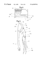
- FIG. 4 is an elevational view, taken partly in section, along line 4 — 4 of FIG. 1;
- FIG. 5 is a plan view of crimping pliers which have been adapted for use with the crimp of this invention
- FIG. 6 is an enlarged, perspective view of the crimp-crushing jaws of the pliers of FIG. 5;
- FIG. 7 is an enlarged perspective view of the crimping jaws of FIG. 6, shown to be holding the crimp of FIG. 1;
- FIG. 8 is a fragmentary enlarged perspective view of another embodiment of the crimping jaws of this invention.
- FIG. 9 is a fragmentary, side elevational view of the crimping jaws of FIG. 8;
- FIG. 10 is a fragmentary, schematic, front elevational view of the crimping pliers of FIG. 8, showing the interaction between the two jaws;
- FIG. 11 is a similar front elevational view of a modification of the crimping jaws from that shown in FIGS. 8-10, with the crimping pliers being otherwise similar to those figures;
- FIG. 12 is a longitudinal sectional view of crimping pliers of this invention.
- malleable metal crimp 10 is shown, being made of a conventional crimp alloy suitable for the purpose.
- crimp 10 has a crimp body 12 that defines a pair of separate, parallel bores 14 , 16 extending through the crimp.
- bores 14 , 16 are for the purpose of receiving a portion of a wire or cable, and for retaining such wire or cable portion as the crimp is collapsed so that the bores 14 , 16 collapse inwardly about the wire or cable portions and retain them with firm retention.
- Crimp 10 also defines a pair of opposed ends 18 , 20 through which the respective bores 14 , 16 extend.
- Ends 18 , 20 each define a pair of circumferentially-spaced, outwardly projecting flanges 22 , 24 on one end and identical flanges 22 a , 24 a on the other end.
- Flanges 22 , 22 a , and 24 , 24 a are respectively positioned on opposite sides of the crimp (and opposite ends of bores 14 , 16 ), to permit the respective flanges to rest against a bone B while providing spacing 26 for crimping jaws between a central portion of the crimp and the bone.
- Each of flanges 22 , 22 a , 24 , 24 a defines a pointed tooth 28 for engaging bone B to resist slippage of the crimp relative to the bone. Teeth 28 can dig into the bone surface to a small degree, when held against the bone under tension of cable or wire passing through bores 14 , 16 , to eliminate the possibility of such lateral slippage along the surface of bone B.
- a central, external groove 30 is defined on the lower side of the crimp (in customary mode of use) as particularly shown in FIGS. 1 and 3.
- Groove 30 facilitates the collapse of crimp 10 in the jaws of crimping pliers, with lower crushing forces being required.
- the opposite side of crimp 10 may carry a shallower groove 32 as shown in particularly FIGS. 1 and 2 , to further facilitate crimp collapse.
- Each of flanges 22 , 22 a , 24 , 24 a preferably defines a circumferential angle about the nearest of the respective bores 14 , 16 of about 30 degrees to 90 degrees for example as shown by angle 34 in FIG. 1, the angle being measured from ends of the outermost periphery of each flange.
- Upper edge 36 of each flange (as illustrated with respect to flange 24 ) preferably angles downwardly as shown from the upper edge of crimp 10 , so as to keep the upstanding height of the crimp above bone B to a minimum.
- each of the flanges are each positioned to one side of a plane enclosing both longitudinal axes of bores 14 , 16 . It can be seen that such a plane extends above each of the centers 38 of the respective flanges 22 , 22 a , 24 , 24 a.
- an improved crimp which carries preferably two lumens for receiving surgical cable or wires.
- the presence of the two lumens make proper tensioning of the surgical cable wrap around the bone easier, and also facilitates cutting off of the surgical cable or wire adjacent to the crimp after the crimp has been crushed, for retaining of the surgical cable or wire in a desired surgical wrap around a bone or the like.
- the nature of the particular wrap of surgical cable or wire incorporating the crimp of this invention may be as chosen by the surgeon and will generally represent conventional techniques.
- crimping pliers 40 are shown comprising a pivotally connected pair of handles 42 , 44 , with each of the handles connecting to a pair of interacting jaw portions 46 , 48 . It can be seen that handle 42 connects with jaw portion 48 through pivots 50 , 55 , while jaw portion 48 connects with jaw portion 46 through pivot 72 , and is integral with handle 44 (FIG. 12 ). The respective handles 42 , 44 are connected together by pivot 52 .
- Jaw portion 48 comprises a pair of laterally spaced crimp retaining prongs 56 defining a crimp space 58 between retaining prongs 56 , plus a recess 60 for retaining crimp 10 as particularly illustrated in FIG. 7 .
- Jaw portion 46 defines a single crimp gripping and crushing projection 62 , which is positioned to move toward crimp space 58 as the jaw portions 46 , 48 are pivoted to a closed, crimp crushing position by the squeezing of handles 42 , 44 .
- Crimp retaining prongs 56 also define outer walls of the respective crimp retaining troughs 60 , which may be considered a single crimp retaining trough if desired.
- crimp space 58 is seen in FIG. 6 to be also defined by a longitudinally extending trough 64 in jaw portion 48 .
- the width of trough 64 is also sufficient to receive jaw 46 , which comprises a plate of uniform, opposed, flat surfaces 66 , which are spaced to fit into longitudinal trough 64 and which define crimp gripping and crushing projection 62 .
- crimp 10 is shown to be carried in jaws 54 of the pliers of FIGS. 5 and 6, a lower edge of crimp 10 being retained by crimp retaining prongs 56 so that the lower side of crimp 10 resides in transverse troughs 60 .
- the other side of crimp 10 is held by gripping and crushing projection 62 , the position of jaws 54 and crimp 10 in FIG. 7 being that prior to crushing of the crimp.
- cable passes through bores 12 , 14 , extending out of both ends of the crimp bores and being involved in a wrap around a bone of a patient or the like as part of orthopedic surgery.
- the cables are pulled tight, so that crimp 10 is driven into contact with bone B upon which it resides (FIGS. 1 and 4 ), following which the crimping action is exerted on crimp 10 by pliers 40 , while the cable remains under tension.
- the cable and crimp are forced together into a unitary system where the cable cannot slip out of or along the crimp, and crimp 40 is affixed on bone B. Then, free ends of the cables may be cut away from one end or the other of bores 12 , 14 .
- FIG. 5 also shows a pivoted, auxiliary handle 57 , which is provided to assist those with smaller hands to close the crimping pliers under pressure.
- Auxiliary handle 57 is attached to pliers handle 42 through pivot 59 so that auxiliary handle 57 can pivot through a limited range as shown.
- Clockwise pivoting as shown in FIG. 5 is limited by an abutment 57 a , which presses against handle 42 when auxiliary handle 57 is in the extreme clockwise position shown in the broken lines.
- a small handed person has less of a reach when he or she uses the auxiliary handle 57 a to initiate closing of the crimp pliers against the resistance which may be afforded by a crimp. Then, when the crimp pliers handles have closed further, the user may grasp handle 42 to complete the crimping process.
- auxiliary handle 57 is of U-shaped cross section so that it can fit around handle 42 in an extreme counterclockwise rotational position, so as not to interfere with the final closing of crimping pliers 40 .
- FIGS. 8-10 portions of the jaws of crimping pliers 40 a are shown, the crimping pliers being otherwise similar to the previously described crimping pliers 40 except as otherwise described herein.
- the respective jaw portions 46 a , 48 a are shown with a more rounded design than their counterparts in the previous embodiment, but the jaws are basically of a structure and function similar to the previous embodiment.
- Crimp retaining prongs 56 a in this embodiment are less pronounced than in the previous embodiment, but still present to retain a crimp in position for the crimping procedure in a manner similar to that of the previous embodiment.
- Upper jaw 46 a also defines a crimp retaining prong 70 to retain an upper edge of a crimp within the jaws.
- Crimp space 58 a is, like the previous embodiment, defined by a longitudinally extending trough 64 a as in the previous embodiment.
- Jaws 46 a , 48 a pivot into open and closed position about pivot 72 , for a simplification of the pivoting system from the previous embodiment.
- jaw 46 a is capable of fitting into longitudinally extending trough 64 a (and the included crimp space 58 a ) for complete, strong crimping action.
- FIG. 11 another design of jaw which is otherwise similar to that disclosed above may be provided where upper jaw 46 b is too wide to fit into longitudinal trough 64 b as defined in lower jaw 48 b .
- Either of the above designs of FIGS. 10 and 11 can be effective in the various embodiments of crimping pliers in accordance with this invention.
- FIG. 12 a design for the pliers of this invention is shown having jaws similar to the embodiment of FIGS. 8-10 but otherwise applicable to the embodiment of FIG. 5, and showing a new embodiment 57 b of auxiliary handle similar to handle 57 , while showing the jaw opening and closing mechanism which is applicable to all previous embodiments.
- Pliers 60 comprises handles 42 b , 44 b as in the previous embodiments, which handles are pivotally connected to jaw portion 48 b .
- Jaw portion 46 b is integral with handle 44 b as in the embodiment of FIG. 5 .
- Pivots 50 b , 52 b , 55 b and 72 b are positioned in similar manner to the corresponding pivots of the FIG. 5 embodiment, for similar purpose.
- Crimping pliers 60 carry an eccentric ratchet member 70 which connects to pivot 55 b , being biased by small and large compression springs 67 , 68 and carrying a ratchet 71 which is engaged by pawl 64 , biased by spring 69 .
- the pawl and ratchet system 64 , 70 requires complete closing of handles 42 b , 44 , when closing is initiated, in order to assure that complete crimping of the crimp takes place. Upon complete closing, the pawl and ratchet disengage to permit opening of the handles, which system is known in the prior art.
- Auxiliary handle 57 b is present for a purpose similar to auxiliary handle 57 of FIG. 5, with handle 57 b being of a somewhat different design.
- handle 57 b is pivotally attached to handle 42 b at pivot 65 , being biased inwardly toward handle 44 b by means of spring 73 to a maximum range as shown, where flat surfaces 74 a but each other to prevent further clockwise rotation of handle 57 b.
- Projection 76 fits into aperture 78 a as auxiliary handle 57 b rotates toward handle 44 b , to provide lateral strength and prevention of lateral motion between the handles in a direction perpendicular to the pivotal plane of motion shown.
Abstract
Description
Claims (25)
Priority Applications (2)
| Application Number | Priority Date | Filing Date | Title |
|---|---|---|---|
| US09/467,436 US6629975B1 (en) | 1999-12-20 | 1999-12-20 | Multiple lumen crimp |
| US10/071,679 US6832532B2 (en) | 1999-12-20 | 2002-02-08 | Multiple lumen crimp |
Applications Claiming Priority (1)
| Application Number | Priority Date | Filing Date | Title |
|---|---|---|---|
| US09/467,436 US6629975B1 (en) | 1999-12-20 | 1999-12-20 | Multiple lumen crimp |
Related Child Applications (1)
| Application Number | Title | Priority Date | Filing Date |
|---|---|---|---|
| US10/071,679 Division US6832532B2 (en) | 1999-12-20 | 2002-02-08 | Multiple lumen crimp |
Publications (1)
| Publication Number | Publication Date |
|---|---|
| US6629975B1 true US6629975B1 (en) | 2003-10-07 |
Family
ID=23855692
Family Applications (2)
| Application Number | Title | Priority Date | Filing Date |
|---|---|---|---|
| US09/467,436 Expired - Lifetime US6629975B1 (en) | 1999-12-20 | 1999-12-20 | Multiple lumen crimp |
| US10/071,679 Expired - Lifetime US6832532B2 (en) | 1999-12-20 | 2002-02-08 | Multiple lumen crimp |
Family Applications After (1)
| Application Number | Title | Priority Date | Filing Date |
|---|---|---|---|
| US10/071,679 Expired - Lifetime US6832532B2 (en) | 1999-12-20 | 2002-02-08 | Multiple lumen crimp |
Country Status (1)
| Country | Link |
|---|---|
| US (2) | US6629975B1 (en) |
Cited By (35)
| Publication number | Priority date | Publication date | Assignee | Title |
|---|---|---|---|---|
| US20050216017A1 (en) * | 2004-03-09 | 2005-09-29 | Louie Fielding | Spinal implant and method for restricting spinal flexion |
| WO2008051423A1 (en) | 2006-10-19 | 2008-05-02 | The Board Of Trustees Of The Leland Stanford Junior University | Methods and systems for constraint of spinous processes with attachment |
| WO2008051802A2 (en) | 2006-10-19 | 2008-05-02 | Simpirica Spine, Inc. | Methods and systems for constraint of multiple spine segments |
| US20090171357A1 (en) * | 2007-12-20 | 2009-07-02 | Medicineloge, Inc. | Collet fixation system |
| US20090248063A1 (en) * | 1999-12-21 | 2009-10-01 | Wotton Iii Harry | Crimping device for cranial cruciate ligament stabilization |
| WO2009149414A1 (en) | 2008-06-06 | 2009-12-10 | Simpirica Spine, Inc. | Methods and apparatus for locking a band |
| WO2009149407A1 (en) | 2008-06-06 | 2009-12-10 | Simpirica Spine, Inc. | Methods and apparatus for locking a band |
| WO2010088621A1 (en) | 2009-02-02 | 2010-08-05 | Simpirica Spine, Inc. | Sacral tether anchor and methods of use |
| WO2010104975A1 (en) | 2009-03-10 | 2010-09-16 | Simpirica Spine, Inc. | Surgical tether apparatus and methods of use |
| US20100249839A1 (en) * | 2009-03-30 | 2010-09-30 | Simpirica Spine, Inc. | Methods and apparatus for improving shear loading capacity of a spinal segment |
| WO2010121256A1 (en) | 2009-04-17 | 2010-10-21 | Simpirica Spine, Inc. | Structures and methods for constraining spinal processes with single connector |
| WO2011017363A1 (en) | 2009-08-04 | 2011-02-10 | Simpirica Spine, Inc. | Methods and systems for increasing the bending stiffness and constraining the spreading of a spinal segment |
| US8029541B2 (en) | 2006-10-19 | 2011-10-04 | Simpirica Spine, Inc. | Methods and systems for laterally stabilized constraint of spinous processes |
| US8162982B2 (en) | 2006-10-19 | 2012-04-24 | Simpirica Spine, Inc. | Methods and systems for constraint of multiple spine segments |
| US8187305B2 (en) | 2008-06-06 | 2012-05-29 | Simpirica Spine, Inc. | Methods and apparatus for deploying spinous process constraints |
| US8328807B2 (en) | 2008-07-09 | 2012-12-11 | Icon Orthopaedic Concepts, Llc | Ankle arthrodesis nail and outrigger assembly |
| US8403961B2 (en) | 2007-06-22 | 2013-03-26 | Simpirica Spine, Inc. | Methods and devices for controlled flexion restriction of spinal segments |
| US8414584B2 (en) | 2008-07-09 | 2013-04-09 | Icon Orthopaedic Concepts, Llc | Ankle arthrodesis nail and outrigger assembly |
| US8523930B2 (en) | 2010-05-14 | 2013-09-03 | Neuraxis, Llc | Methods and devices for cooling spinal tissue |
| US8529606B2 (en) | 2009-03-10 | 2013-09-10 | Simpirica Spine, Inc. | Surgical tether apparatus and methods of use |
| US8696710B2 (en) | 2010-10-06 | 2014-04-15 | Simpirica Spine, Inc. | Device and accessories for limiting flexion |
| US8721642B1 (en) * | 2013-01-28 | 2014-05-13 | Neuraxis, Llc | Tissue cooling clamps and related methods |
| US8911486B1 (en) | 2013-09-16 | 2014-12-16 | Neuraxis, Llc | Implantable devices for thermal therapy and related methods |
| US9107706B2 (en) | 2009-03-10 | 2015-08-18 | Simpirica Spine, Inc. | Surgical tether apparatus and methods of use |
| US9265543B2 (en) | 2011-12-27 | 2016-02-23 | Pioneer Surgical Technology, Inc. | Bone plate system and method |
| US9308123B2 (en) | 2013-09-16 | 2016-04-12 | Neuraxis, Llc | Methods and devices for applying localized thermal therapy |
| US9333021B2 (en) | 2012-11-21 | 2016-05-10 | Pioneer Surgical Technology, Inc. | Tensioning instrument |
| US9439698B2 (en) | 2013-03-15 | 2016-09-13 | Frontier Medical Devices, Inc. | Cable fixation device |
| US10092331B2 (en) | 2008-09-03 | 2018-10-09 | Empirical Spine, Inc. | Methods and apparatus for coupling a prosthesis to a spinal segment |
| US10314635B2 (en) | 2014-05-28 | 2019-06-11 | A&E Advanced Closure Systems, Llc | Tensioning instruments |
| US10463410B2 (en) | 2016-01-22 | 2019-11-05 | A&E Advanced Closure Systems, Llc | Bone plate having a connector and a connector for a surgical loop |
| US10485600B2 (en) | 2016-07-29 | 2019-11-26 | A&E Advanced Closure Systems, Llc | Surgical cable tensioner |
| US10765465B2 (en) | 2012-11-21 | 2020-09-08 | A&E Advanced Closure Systems, Llc | Tensioning instrument |
| US10881437B2 (en) | 2013-12-05 | 2021-01-05 | A&E Advanced Closure Systems, Llc | Bone plate system and method |
| US10966772B2 (en) | 2013-03-15 | 2021-04-06 | J.M. Longyear Manufacturing Llc | Cable fixation device, instruments, and methods |
Families Citing this family (17)
| Publication number | Priority date | Publication date | Assignee | Title |
|---|---|---|---|---|
| US8568442B2 (en) * | 2005-06-14 | 2013-10-29 | Karl Storz Gmbh & Co. Kg | Medical gripping and/or cutting instrument |
| WO2008106575A1 (en) | 2007-02-28 | 2008-09-04 | Synthes Usa, Llc | Grooved crimp with a set screw |
| EP2128931B1 (en) * | 2007-03-16 | 2016-06-29 | Fujitsu Limited | Antenna arranging method and mounting device for communication device, and antenna device |
| US8312755B1 (en) * | 2007-11-28 | 2012-11-20 | Rostra Tool Company | Crimping tool with third handle and method of use |
| SE533864C2 (en) * | 2009-04-30 | 2011-02-15 | Pressmaster Ab | ratchet mechanism |
| US8133235B2 (en) | 2009-10-09 | 2012-03-13 | Zimmer, Inc. | One-way bearing cable tensioning tool |
| US8739594B2 (en) * | 2011-09-15 | 2014-06-03 | Danny Anderson | Electrical connector crimping plier tool |
| JP6657117B2 (en) * | 2014-04-30 | 2020-03-04 | デピュイ・シンセス・プロダクツ・インコーポレイテッド | Tensioning device and associated bone fixation system |
| CN104490461A (en) * | 2014-11-28 | 2015-04-08 | 江苏双羊医疗器械有限公司 | Crimping pliers |
| CN104490462A (en) * | 2014-12-04 | 2015-04-08 | 江苏双羊医疗器械有限公司 | Lock catch for locking titanium cable |
| US9138009B1 (en) * | 2014-12-08 | 2015-09-22 | Louis J. Frusco | Shellfish opener |
| WO2017145337A1 (en) * | 2016-02-25 | 2017-08-31 | オリンパス株式会社 | Needle holder and suture set |
| FR3066901B1 (en) * | 2017-06-06 | 2019-07-12 | Xavier Renard | SYSTEM FOR SOLIDARIZING TWO MEDICAL PINS |
| CN207710606U (en) * | 2017-12-31 | 2018-08-10 | 诸暨市艾拓五金工具有限公司 | Clamp pliers with crimping, shearing function |
| US10953527B2 (en) | 2018-02-05 | 2021-03-23 | Oetiker Tool Corporation | Crimping tool for band clamp |
| CN116983034A (en) * | 2018-03-22 | 2023-11-03 | 奥林巴斯株式会社 | Needle holder |
| CN110948411A (en) * | 2019-12-09 | 2020-04-03 | 佳威科技(海安)有限公司 | Medical anti-withdrawal flat joint compressor |
Citations (12)
| Publication number | Priority date | Publication date | Assignee | Title |
|---|---|---|---|---|
| US2461030A (en) * | 1945-03-06 | 1949-02-08 | American Steel & Wire Co | Method of making torpedo nets |
| US3802438A (en) * | 1972-03-31 | 1974-04-09 | Technibiotics | Surgical instrument |
| US4269180A (en) * | 1978-03-30 | 1981-05-26 | Dall Desmond Meiring | Bone fastener for the greater trochanter |
| US4966600A (en) | 1989-01-26 | 1990-10-30 | Songer Robert J | Surgical securance method |
| US5116340A (en) | 1989-01-26 | 1992-05-26 | Songer Robert J | Surgical securance apparatus |
| US5415658A (en) | 1993-12-14 | 1995-05-16 | Pioneer Laboratories, Inc. | Surgical cable loop connector |
| US5536270A (en) | 1994-02-24 | 1996-07-16 | Pioneer Laboratories, Inc. | Cable system for bone securance |
| US5649927A (en) | 1995-09-27 | 1997-07-22 | Pioneer Laboratories, Inc. | Cable crimp system |
| US5797915A (en) * | 1996-04-17 | 1998-08-25 | Pierson, Iii; Raymond H. | Cerclage system |
| US5941881A (en) * | 1998-01-09 | 1999-08-24 | Medidea, Llc | Bone fastening apparatus and related procedures |
| US6017347A (en) * | 1995-06-01 | 2000-01-25 | Acumed, Inc. | Wire clamp assembly |
| US6120505A (en) * | 1995-06-01 | 2000-09-19 | Acumed, Inc. | Wire clamp assembly |
Family Cites Families (13)
| Publication number | Priority date | Publication date | Assignee | Title |
|---|---|---|---|---|
| US1978543A (en) * | 1934-02-24 | 1934-10-30 | K D Mfg Co | Locking means |
| BE672995A (en) * | 1965-11-29 | 1966-03-16 | ||
| US4353240A (en) * | 1980-01-15 | 1982-10-12 | Toolema Ab | Crimping tool |
| US4541312A (en) * | 1981-03-06 | 1985-09-17 | Petersen Manufacturing Co., Inc. | Long nose locking plier |
| US4643054A (en) * | 1985-12-30 | 1987-02-17 | Nelson Gary E | Quick squeeze tool |
| US5797958A (en) * | 1989-12-05 | 1998-08-25 | Yoon; Inbae | Endoscopic grasping instrument with scissors |
| CA2106523A1 (en) * | 1992-10-06 | 1994-04-07 | Jude S. Sauer | Surgical device to prepare body tissue for anastomosis |
| US5335531A (en) * | 1993-05-04 | 1994-08-09 | Square D Company | Compression tool head assembly |
| US5545168A (en) * | 1994-03-11 | 1996-08-13 | Burke; Dennis W. | Apparatus for both tensioning and crimping a surgical wire |
| US5951587A (en) * | 1997-10-09 | 1999-09-14 | Ethicon-Endo-Surgery, Inc. | Needle holder with suture filament grasping abilities |
| US6099539A (en) * | 1998-07-27 | 2000-08-08 | Thomas J. Fogarty | Surgical clamp pad with interdigitating teeth |
| EP1092487A3 (en) * | 1999-10-15 | 2004-08-25 | Gustav Klauke GmbH | Pressing tool with pressure jaws |
| US6227030B1 (en) * | 1999-12-17 | 2001-05-08 | Fci Usa, Inc. | Electrical connector crimping die with over-crimp prevention surface and method |
-
1999
- 1999-12-20 US US09/467,436 patent/US6629975B1/en not_active Expired - Lifetime
-
2002
- 2002-02-08 US US10/071,679 patent/US6832532B2/en not_active Expired - Lifetime
Patent Citations (12)
| Publication number | Priority date | Publication date | Assignee | Title |
|---|---|---|---|---|
| US2461030A (en) * | 1945-03-06 | 1949-02-08 | American Steel & Wire Co | Method of making torpedo nets |
| US3802438A (en) * | 1972-03-31 | 1974-04-09 | Technibiotics | Surgical instrument |
| US4269180A (en) * | 1978-03-30 | 1981-05-26 | Dall Desmond Meiring | Bone fastener for the greater trochanter |
| US4966600A (en) | 1989-01-26 | 1990-10-30 | Songer Robert J | Surgical securance method |
| US5116340A (en) | 1989-01-26 | 1992-05-26 | Songer Robert J | Surgical securance apparatus |
| US5415658A (en) | 1993-12-14 | 1995-05-16 | Pioneer Laboratories, Inc. | Surgical cable loop connector |
| US5536270A (en) | 1994-02-24 | 1996-07-16 | Pioneer Laboratories, Inc. | Cable system for bone securance |
| US6017347A (en) * | 1995-06-01 | 2000-01-25 | Acumed, Inc. | Wire clamp assembly |
| US6120505A (en) * | 1995-06-01 | 2000-09-19 | Acumed, Inc. | Wire clamp assembly |
| US5649927A (en) | 1995-09-27 | 1997-07-22 | Pioneer Laboratories, Inc. | Cable crimp system |
| US5797915A (en) * | 1996-04-17 | 1998-08-25 | Pierson, Iii; Raymond H. | Cerclage system |
| US5941881A (en) * | 1998-01-09 | 1999-08-24 | Medidea, Llc | Bone fastening apparatus and related procedures |
Non-Patent Citations (1)
| Title |
|---|
| Howmedica brochure, The Dall-Miles Trochanter Cable Grip System (Date Unknown). |
Cited By (63)
| Publication number | Priority date | Publication date | Assignee | Title |
|---|---|---|---|---|
| US20090248063A1 (en) * | 1999-12-21 | 2009-10-01 | Wotton Iii Harry | Crimping device for cranial cruciate ligament stabilization |
| US8523904B2 (en) | 2004-03-09 | 2013-09-03 | The Board Of Trustees Of The Leland Stanford Junior University | Methods and systems for constraint of spinous processes with attachment |
| US9149304B2 (en) | 2004-03-09 | 2015-10-06 | The Board Of Trustees Of The Leland Sanford Junior University | Methods and systems for constraint of spinous processes with attachment |
| US8486110B2 (en) | 2004-03-09 | 2013-07-16 | The Board Of Trustees Of The Leland Stanford Junior University | Spinal implant and method for restricting spinal flexion |
| US7458981B2 (en) | 2004-03-09 | 2008-12-02 | The Board Of Trustees Of The Leland Stanford Junior University | Spinal implant and method for restricting spinal flexion |
| US8216275B2 (en) | 2004-03-09 | 2012-07-10 | The Board Of Trustees Of The Leland Stanford Junior University | Spinal implant and method for restricting spinal flexion |
| US8105363B2 (en) | 2004-03-09 | 2012-01-31 | The Board Of Trustees Of The Leland Stanford Junior University | Spinal implant and method for restricting spinal flexion |
| US20050216017A1 (en) * | 2004-03-09 | 2005-09-29 | Louie Fielding | Spinal implant and method for restricting spinal flexion |
| US10080589B2 (en) | 2004-03-09 | 2018-09-25 | The Board Of Trustees Of The Leland Stanford Junior University | Methods and systems for constraint of spinous processes with attachment |
| WO2008051423A1 (en) | 2006-10-19 | 2008-05-02 | The Board Of Trustees Of The Leland Stanford Junior University | Methods and systems for constraint of spinous processes with attachment |
| WO2008051801A2 (en) | 2006-10-19 | 2008-05-02 | Simpirica Spine, Inc. | Structures and methods for constraining spinal processes with single connector |
| US8187307B2 (en) | 2006-10-19 | 2012-05-29 | Simpirica Spine, Inc. | Structures and methods for constraining spinal processes with single connector |
| US8790372B2 (en) | 2006-10-19 | 2014-07-29 | Simpirica Spine, Inc. | Methods and systems for constraint of multiple spine segments |
| US9295499B2 (en) | 2006-10-19 | 2016-03-29 | Empirical Spine, Inc. | Methods and systems for laterally stabilized constraint of spinous processes |
| US8029541B2 (en) | 2006-10-19 | 2011-10-04 | Simpirica Spine, Inc. | Methods and systems for laterally stabilized constraint of spinous processes |
| WO2008051802A2 (en) | 2006-10-19 | 2008-05-02 | Simpirica Spine, Inc. | Methods and systems for constraint of multiple spine segments |
| US8162982B2 (en) | 2006-10-19 | 2012-04-24 | Simpirica Spine, Inc. | Methods and systems for constraint of multiple spine segments |
| US8454660B2 (en) | 2006-10-19 | 2013-06-04 | Simpirica Spine, Inc. | Methods and systems for laterally stabilized constraint of spinous processes |
| US8403964B2 (en) | 2007-06-22 | 2013-03-26 | Simpirica Spine, Inc. | Methods and systems for increasing the bending stiffness and constraining the spreading of a spinal segment |
| US8403961B2 (en) | 2007-06-22 | 2013-03-26 | Simpirica Spine, Inc. | Methods and devices for controlled flexion restriction of spinal segments |
| US8241288B2 (en) | 2007-12-20 | 2012-08-14 | Imds Corporation | Collet fixation system |
| US20090171357A1 (en) * | 2007-12-20 | 2009-07-02 | Medicineloge, Inc. | Collet fixation system |
| WO2009149407A1 (en) | 2008-06-06 | 2009-12-10 | Simpirica Spine, Inc. | Methods and apparatus for locking a band |
| US8308771B2 (en) | 2008-06-06 | 2012-11-13 | Simpirica Spine, Inc. | Methods and apparatus for locking a band |
| US8187305B2 (en) | 2008-06-06 | 2012-05-29 | Simpirica Spine, Inc. | Methods and apparatus for deploying spinous process constraints |
| WO2009149414A1 (en) | 2008-06-06 | 2009-12-10 | Simpirica Spine, Inc. | Methods and apparatus for locking a band |
| US8328807B2 (en) | 2008-07-09 | 2012-12-11 | Icon Orthopaedic Concepts, Llc | Ankle arthrodesis nail and outrigger assembly |
| US9226783B2 (en) | 2008-07-09 | 2016-01-05 | Icon Orthopaedic Concepts, Llc | Ankle arthrodesis nail and outrigger assembly |
| US8414584B2 (en) | 2008-07-09 | 2013-04-09 | Icon Orthopaedic Concepts, Llc | Ankle arthrodesis nail and outrigger assembly |
| US10864022B2 (en) | 2008-09-03 | 2020-12-15 | Empirical Spine, Inc. | Methods and apparatus for coupling a prosthesis to a spinal segment |
| US10092331B2 (en) | 2008-09-03 | 2018-10-09 | Empirical Spine, Inc. | Methods and apparatus for coupling a prosthesis to a spinal segment |
| WO2010088621A1 (en) | 2009-02-02 | 2010-08-05 | Simpirica Spine, Inc. | Sacral tether anchor and methods of use |
| US8529607B2 (en) | 2009-02-02 | 2013-09-10 | Simpirica Spine, Inc. | Sacral tether anchor and methods of use |
| US8529606B2 (en) | 2009-03-10 | 2013-09-10 | Simpirica Spine, Inc. | Surgical tether apparatus and methods of use |
| WO2010104975A1 (en) | 2009-03-10 | 2010-09-16 | Simpirica Spine, Inc. | Surgical tether apparatus and methods of use |
| US10314623B2 (en) | 2009-03-10 | 2019-06-11 | Empirical Spine, Inc. | Surgical tether apparatus and methods of use |
| US9107706B2 (en) | 2009-03-10 | 2015-08-18 | Simpirica Spine, Inc. | Surgical tether apparatus and methods of use |
| US8562653B2 (en) | 2009-03-10 | 2013-10-22 | Simpirica Spine, Inc. | Surgical tether apparatus and methods of use |
| US8668719B2 (en) | 2009-03-30 | 2014-03-11 | Simpirica Spine, Inc. | Methods and apparatus for improving shear loading capacity of a spinal segment |
| US20100249839A1 (en) * | 2009-03-30 | 2010-09-30 | Simpirica Spine, Inc. | Methods and apparatus for improving shear loading capacity of a spinal segment |
| WO2010121256A1 (en) | 2009-04-17 | 2010-10-21 | Simpirica Spine, Inc. | Structures and methods for constraining spinal processes with single connector |
| WO2011017363A1 (en) | 2009-08-04 | 2011-02-10 | Simpirica Spine, Inc. | Methods and systems for increasing the bending stiffness and constraining the spreading of a spinal segment |
| US8523930B2 (en) | 2010-05-14 | 2013-09-03 | Neuraxis, Llc | Methods and devices for cooling spinal tissue |
| US8696710B2 (en) | 2010-10-06 | 2014-04-15 | Simpirica Spine, Inc. | Device and accessories for limiting flexion |
| US9265543B2 (en) | 2011-12-27 | 2016-02-23 | Pioneer Surgical Technology, Inc. | Bone plate system and method |
| US10426532B2 (en) | 2012-11-21 | 2019-10-01 | A&E Advanced Closure Systems, Llc | Bone plate system and method |
| US9561064B2 (en) | 2012-11-21 | 2017-02-07 | Pioneer Surgical Technology, Inc. | Bone plate system and method |
| US9333021B2 (en) | 2012-11-21 | 2016-05-10 | Pioneer Surgical Technology, Inc. | Tensioning instrument |
| US10765465B2 (en) | 2012-11-21 | 2020-09-08 | A&E Advanced Closure Systems, Llc | Tensioning instrument |
| US8721642B1 (en) * | 2013-01-28 | 2014-05-13 | Neuraxis, Llc | Tissue cooling clamps and related methods |
| US10966772B2 (en) | 2013-03-15 | 2021-04-06 | J.M. Longyear Manufacturing Llc | Cable fixation device, instruments, and methods |
| US9439698B2 (en) | 2013-03-15 | 2016-09-13 | Frontier Medical Devices, Inc. | Cable fixation device |
| US10179065B2 (en) | 2013-09-16 | 2019-01-15 | Neuraxis Llc | Implantable devices for thermal therapy and related methods |
| US8911486B1 (en) | 2013-09-16 | 2014-12-16 | Neuraxis, Llc | Implantable devices for thermal therapy and related methods |
| US10772760B2 (en) | 2013-09-16 | 2020-09-15 | Neuraxis, Llc | Implantable devices for thermal therapy and related methods |
| US9308123B2 (en) | 2013-09-16 | 2016-04-12 | Neuraxis, Llc | Methods and devices for applying localized thermal therapy |
| US11123222B2 (en) | 2013-09-16 | 2021-09-21 | Neuraxis, Llc | Methods and devices for applying localized thermal therapy |
| US10881437B2 (en) | 2013-12-05 | 2021-01-05 | A&E Advanced Closure Systems, Llc | Bone plate system and method |
| US10314635B2 (en) | 2014-05-28 | 2019-06-11 | A&E Advanced Closure Systems, Llc | Tensioning instruments |
| US11298172B2 (en) | 2014-05-28 | 2022-04-12 | A&E Advanced Closure Systems, Llc | Tensioning instruments |
| US10463410B2 (en) | 2016-01-22 | 2019-11-05 | A&E Advanced Closure Systems, Llc | Bone plate having a connector and a connector for a surgical loop |
| US11413077B2 (en) | 2016-01-22 | 2022-08-16 | A&E Advanced Closure Systems, Llc | Bone plate having a connector and a connector for a surgical loop |
| US10485600B2 (en) | 2016-07-29 | 2019-11-26 | A&E Advanced Closure Systems, Llc | Surgical cable tensioner |
Also Published As
| Publication number | Publication date |
|---|---|
| US6832532B2 (en) | 2004-12-21 |
| US20020120282A1 (en) | 2002-08-29 |
Similar Documents
| Publication | Publication Date | Title |
|---|---|---|
| US6629975B1 (en) | Multiple lumen crimp | |
| US5651283A (en) | Bone plate shaping device | |
| US10426532B2 (en) | Bone plate system and method | |
| US5741259A (en) | Surgical fastener device for use in bone fracture fixation | |
| KR101220305B1 (en) | cranial flap clamp instrument | |
| US7452360B2 (en) | Method and apparatus for clamping surgical wires or cables | |
| US7135021B2 (en) | Plug-type device for retrieving spinal column under treatment | |
| US5649927A (en) | Cable crimp system | |
| US5620452A (en) | Surgical clip with ductile tissue penetrating members | |
| US20130218200A1 (en) | Tissue approximation device | |
| JP2004504883A (en) | Cranial valve fastener and device for the fastener | |
| US6641588B2 (en) | Surgical tool for tensioning a cranial-flap clamp | |
| JP2001511678A (en) | Rod introduction forceps | |
| JPH0516861B2 (en) | ||
| US6322363B1 (en) | Dental pliers | |
| US7063704B2 (en) | Surgical trimming tool | |
| EP1448104B1 (en) | Surgical tool for tensioning a cranial-flap clamp | |
| EP0625085A1 (en) | Crimper | |
| JP2561226B2 (en) | Bone tie fittings | |
| EP1604618A1 (en) | Plug-type device for retrieving spinal column under treatment |
Legal Events
| Date | Code | Title | Description |
|---|---|---|---|
| AS | Assignment |
Owner name: PIONEER LABORATORIES, INC., MICHIGAN Free format text: ASSIGNMENT OF ASSIGNORS INTEREST;ASSIGNORS:KILPELA, THOMAS S.;BERREVOETS, GREG A.;REEL/FRAME:010605/0094 Effective date: 19991216 |
|
| AS | Assignment |
Owner name: ROBERT BOSCH CORPORATION, ILLINOIS Free format text: ASSIGNMENT OF ASSIGNORS INTEREST;ASSIGNOR:ROBERT BOSCH TECHNOLOGY CORPORATION;REEL/FRAME:011826/0582 Effective date: 20010514 |
|
| STCF | Information on status: patent grant |
Free format text: PATENTED CASE |
|
| FPAY | Fee payment |
Year of fee payment: 4 |
|
| AS | Assignment |
Owner name: PIONEER SURGICAL TECHNOLOGY, INC., MICHIGAN Free format text: CHANGE OF NAME;ASSIGNOR:PIONEER LABORATORIES, INC.;REEL/FRAME:020105/0308 Effective date: 20061211 Owner name: PIONEER SURGICAL TECHNOLOGY, INC.,MICHIGAN Free format text: CHANGE OF NAME;ASSIGNOR:PIONEER LABORATORIES, INC.;REEL/FRAME:020105/0308 Effective date: 20061211 |
|
| FPAY | Fee payment |
Year of fee payment: 8 |
|
| AS | Assignment |
Owner name: TD BANK, N.A., AS ADMINISTRATIVE AGENT, FLORIDA Free format text: SECURITY AGREEMENT;ASSIGNOR:PIONEER SURGICAL TECHNOLOGY, INC.;REEL/FRAME:030892/0193 Effective date: 20130716 |
|
| FEPP | Fee payment procedure |
Free format text: PAT HOLDER NO LONGER CLAIMS SMALL ENTITY STATUS, ENTITY STATUS SET TO UNDISCOUNTED (ORIGINAL EVENT CODE: STOL); ENTITY STATUS OF PATENT OWNER: LARGE ENTITY |
|
| FPAY | Fee payment |
Year of fee payment: 12 |
|
| AS | Assignment |
Owner name: JPMORGAN CHASE BANK, N.A., AS THE ADMINISTRATIVE AGENT, ILLINOIS Free format text: SECURITY INTEREST;ASSIGNORS:RTI SURGICAL, INC.;PIONEER SURGICAL TECHNOLOGY, INC.;TUTOGEN MEDICAL, INC.;REEL/FRAME:046303/0926 Effective date: 20180605 Owner name: JPMORGAN CHASE BANK, N.A., AS THE ADMINISTRATIVE A Free format text: SECURITY INTEREST;ASSIGNORS:RTI SURGICAL, INC.;PIONEER SURGICAL TECHNOLOGY, INC.;TUTOGEN MEDICAL, INC.;REEL/FRAME:046303/0926 Effective date: 20180605 |
|
| AS | Assignment |
Owner name: PIONEER SURGICAL TECHNOLOGY, INC., FLORIDA Free format text: RELEASE BY SECURED PARTY;ASSIGNOR:TD BANK, N.A., AS ADMINISTRATIVE AGENT;REEL/FRAME:046320/0040 Effective date: 20180605 |
|
| AS | Assignment |
Owner name: ARES CAPITAL CORPORATION, AS ADMINISTRATIVE AGENT, Free format text: SECURITY INTEREST;ASSIGNORS:RTI SURGICAL, INC.;PIONEER SURGICAL TECHNOLOGY, INC.;TUTOGEN MEDICAL, INC.;AND OTHERS;REEL/FRAME:048543/0505 Effective date: 20190308 Owner name: ARES CAPITAL CORPORATION, AS ADMINISTRATIVE AGENT, NEW YORK Free format text: SECURITY INTEREST;ASSIGNORS:RTI SURGICAL, INC.;PIONEER SURGICAL TECHNOLOGY, INC.;TUTOGEN MEDICAL, INC.;AND OTHERS;REEL/FRAME:048543/0505 Effective date: 20190308 |
|
| AS | Assignment |
Owner name: FOURTH DIMENSION SPINE, LLC, NEW YORK Free format text: RELEASE BY SECURED PARTY;ASSIGNOR:ARES CAPITAL CORPORATION, AS AGENT;REEL/FRAME:053257/0652 Effective date: 20200720 Owner name: PIONEER SURGICAL TECHNOLOGY, INC., FLORIDA Free format text: RELEASE BY SECURED PARTY;ASSIGNOR:ARES CAPITAL CORPORATION, AS AGENT;REEL/FRAME:053257/0652 Effective date: 20200720 Owner name: TUTOGEN MEDICAL, INC., FLORIDA Free format text: RELEASE BY SECURED PARTY;ASSIGNOR:ARES CAPITAL CORPORATION, AS AGENT;REEL/FRAME:053257/0652 Effective date: 20200720 Owner name: PARADIGM SPINE, LLC, NEW YORK Free format text: RELEASE BY SECURED PARTY;ASSIGNOR:ARES CAPITAL CORPORATION, AS AGENT;REEL/FRAME:053257/0652 Effective date: 20200720 Owner name: RTI SURGICAL, INC., FLORIDA Free format text: RELEASE BY SECURED PARTY;ASSIGNOR:ARES CAPITAL CORPORATION, AS AGENT;REEL/FRAME:053257/0652 Effective date: 20200720 |
|
| AS | Assignment |
Owner name: TUTOGEN MEDICAL, INC., FLORIDA Free format text: RELEASE BY SECURED PARTY;ASSIGNOR:JPMORGAN CHASE BANK, N.A., AS ADMINISTRATIVE AGENT;REEL/FRAME:053260/0398 Effective date: 20200720 Owner name: RTI SURGICAL, INC., FLORIDA Free format text: RELEASE BY SECURED PARTY;ASSIGNOR:JPMORGAN CHASE BANK, N.A., AS ADMINISTRATIVE AGENT;REEL/FRAME:053260/0398 Effective date: 20200720 Owner name: PIONEER SURGICAL TECHNOLOGY, INC., FLORIDA Free format text: RELEASE BY SECURED PARTY;ASSIGNOR:JPMORGAN CHASE BANK, N.A., AS ADMINISTRATIVE AGENT;REEL/FRAME:053260/0398 Effective date: 20200720 |