US6629718B2 - Motor vehicle having a fixed roof which can be opened and method of making same - Google Patents
Motor vehicle having a fixed roof which can be opened and method of making same Download PDFInfo
- Publication number
- US6629718B2 US6629718B2 US10/206,937 US20693702A US6629718B2 US 6629718 B2 US6629718 B2 US 6629718B2 US 20693702 A US20693702 A US 20693702A US 6629718 B2 US6629718 B2 US 6629718B2
- Authority
- US
- United States
- Prior art keywords
- rear window
- roof
- supporting
- pivot axis
- fixed
- Prior art date
- Legal status (The legal status is an assumption and is not a legal conclusion. Google has not performed a legal analysis and makes no representation as to the accuracy of the status listed.)
- Expired - Fee Related
Links
Images


Classifications
-
- B—PERFORMING OPERATIONS; TRANSPORTING
- B60—VEHICLES IN GENERAL
- B60J—WINDOWS, WINDSCREENS, NON-FIXED ROOFS, DOORS, OR SIMILAR DEVICES FOR VEHICLES; REMOVABLE EXTERNAL PROTECTIVE COVERINGS SPECIALLY ADAPTED FOR VEHICLES
- B60J1/00—Windows; Windscreens; Accessories therefor
- B60J1/18—Windows; Windscreens; Accessories therefor arranged at the vehicle rear
- B60J1/1807—Windows; Windscreens; Accessories therefor arranged at the vehicle rear movable for vehicles with convertible top
- B60J1/1823—Windows; Windscreens; Accessories therefor arranged at the vehicle rear movable for vehicles with convertible top adjustable relative to hard- or soft-top, e.g. pivotable
-
- B—PERFORMING OPERATIONS; TRANSPORTING
- B60—VEHICLES IN GENERAL
- B60J—WINDOWS, WINDSCREENS, NON-FIXED ROOFS, DOORS, OR SIMILAR DEVICES FOR VEHICLES; REMOVABLE EXTERNAL PROTECTIVE COVERINGS SPECIALLY ADAPTED FOR VEHICLES
- B60J7/00—Non-fixed roofs; Roofs with movable panels, e.g. rotary sunroofs
- B60J7/08—Non-fixed roofs; Roofs with movable panels, e.g. rotary sunroofs of non-sliding type, i.e. movable or removable roofs or panels, e.g. let-down tops or roofs capable of being easily detached or of assuming a collapsed or inoperative position
- B60J7/12—Non-fixed roofs; Roofs with movable panels, e.g. rotary sunroofs of non-sliding type, i.e. movable or removable roofs or panels, e.g. let-down tops or roofs capable of being easily detached or of assuming a collapsed or inoperative position foldable; Tensioning mechanisms therefor, e.g. struts
- B60J7/14—Non-fixed roofs; Roofs with movable panels, e.g. rotary sunroofs of non-sliding type, i.e. movable or removable roofs or panels, e.g. let-down tops or roofs capable of being easily detached or of assuming a collapsed or inoperative position foldable; Tensioning mechanisms therefor, e.g. struts with a plurality of rigid plate-like elements or rigid non plate-like elements, e.g. with non-slidable, but pivotable or foldable movement
- B60J7/143—Non-fixed roofs; Roofs with movable panels, e.g. rotary sunroofs of non-sliding type, i.e. movable or removable roofs or panels, e.g. let-down tops or roofs capable of being easily detached or of assuming a collapsed or inoperative position foldable; Tensioning mechanisms therefor, e.g. struts with a plurality of rigid plate-like elements or rigid non plate-like elements, e.g. with non-slidable, but pivotable or foldable movement for covering the passenger compartment
- B60J7/146—Non-fixed roofs; Roofs with movable panels, e.g. rotary sunroofs of non-sliding type, i.e. movable or removable roofs or panels, e.g. let-down tops or roofs capable of being easily detached or of assuming a collapsed or inoperative position foldable; Tensioning mechanisms therefor, e.g. struts with a plurality of rigid plate-like elements or rigid non plate-like elements, e.g. with non-slidable, but pivotable or foldable movement for covering the passenger compartment all elements being folded in same orientation and stacked fashion
Definitions
- the invention relates to a motor vehicle having a fixed roof which can be opened and has a front and a rear roof part which are connected to each other in an articulated manner and, controlled by way of a main link arrangement, can be shifted between a closing position and a storage position in a rear storage space, having a fixed rear window which is mounted pivotably on lateral roof pillars and a pivot axis which runs in a central region of the rear window in a transverse direction of the vehicle, the rear window being driven in a rotational manner relative to the roof pillars during opening and closing movement of the fixed roof, and the rear window, after reaching the closing position of the fixed roof, being pressed via a rotational drive against a sealing seat interacting with the rear window.
- a motor vehicle of this type having a fixed roof which can be opened and which comprises a front and a rear roof part is known from German Patent Document DE 197 51 660 C1, corresponding to U.S. Pat. No. 6,123,381.
- the two roof parts are connected to each other in an articulated manner and, controlled by means of a main link arrangement, can be shifted between a closing position and a storage position in a rear storage space.
- the rear roof part comprises a fixed rear window which is mounted pivotably on lateral roof pillars and the pivot axis of which runs in the central region of the rear window in the transverse direction of the vehicle.
- the said rear window In order to store the rear window in a space-saving manner in the rear storage space with its curvature in the same direction as the front roof part, the said rear window is driven in a rotational manner relative to the roof pillars during the opening and closing movement of the fixed roof.
- a further lever arrangement coupled to the main link arrangement is used here as the rotational drive.
- An aspect of the invention is therefore to provide a motor vehicle of the type mentioned at the beginning, in which the rear window is sealed against the sealing seat in a simplified and more reliable manner.
- a supporting arrangement which comprises at least one supporting element which, when pushed forward, enables the rear window to be acted upon by a rotational force ensuring the sealing seat of the rear window.
- a supporting arrangement having at least one supporting element which supporting element, when pushed forward enables the rotatable rear window to be acted upon by a further rotational force which ensures the sealing seat of the rear window.
- the supporting arrangement enables the rear window, which is already pressed against the seal by way of the rotational drive, to be further rotated through a small angular extent in order to achieve an improved sealing seat. This also enables the rotational drive to be simplified and to be of smaller dimensions, since the sealing force can be applied by the supporting arrangement.
- a supporting arrangement which is attached to the associated main link can be designed in a particularly simple manner. As a result, when the roof is closed, the supporting arrangement automatically moves into its supporting position.
- torsional reinforcement is particularly good if a respective centering element is arranged in a mirror-symmetrical arrangement on the lateral roof pillars, the said centering element interacting with a corresponding centering element of the rear window.
- FIG. 1 shows a schematic sectional view of the closed fixed roof along the central longitudinal plane of the motor vehicle together with the front and rear roof part which are connected to each other in an articulated manner and with the main link arrangement for opening the roof;
- FIGS. 2 and 3 show a schematic sectional view of the fixed roof during a first and second stage of the storing process of the roof in a rear storage space;
- FIG. 4 shows a schematic sectional view of the fixed roof in the stored state
- FIG. 5 shows a schematic partial perspective view from the right at the front in the direction to the rear at the top of the rear roof part and one of the main links in the closed state of the roof;
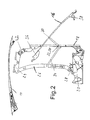
- FIG. 6 shows an enlarged partial perspective view of the rear roof part shown in FIG. 5 and the main link in the region of the roof pillar;
- FIG. 7 shows a schematic cross section along the line VII—VII in FIG. 6 through the rear roof part in the region of the roof pillar;
- FIG. 8 shows a schematic cross section along the line VIII—VIII in FIG. 6 through the rear roof part in the region of the roof pillar.
- FIG. 1 illustrates, in a schematic sectional view along the central longitudinal plane, the fixed roof, which can be opened, of a motor vehicle, in the closed state.
- the fixed roof comprises a front and rear roof part 10 , 12 which are connected to each other in an articulated manner, the front side of the front roof part 10 adjoining a windscreen frame (not shown) and the rear side of the rear roof part 12 ending level with the tailgate of the motor vehicle.
- the front and rear roof part 10 , 12 controlled by way of a main link arrangement 14 (explained in greater detail below), can be shifted between the closing position (shown here) and a storage position (shown in FIG. 4) in a rear storage space.
- the rear roof part 12 comprises, as basic parts, a fixed rear window 16 made of glass or plastic and lateral C-pillars or roof pillars 18 , the rear window 16 being mounted (in a manner also described below) on the lateral roof pillars 18 in a manner such that it can pivot about a pivot axis SH running in its central region in the transverse direction of the vehicle.
- the lateral C-pillars are connected to a main bearing 20 , in each case in an articulated manner, while at their front ends they each have a main pivot point 22 on which a hinge 24 for the front roof part 10 is also articulated. Articulated on that end of the hinge 24 which faces away from the main pivot point 22 is an end, which is concealed in FIG. 1, of a main link 26 of the main link arrangement 14 , the other end of which is connected to the main bearing 20 via an intermediate lever 28 .
- the two main links 26 run laterally in the vicinity of the C-pillars.
- the rear window 16 is rigidly connected, in a manner to be explained in greater detail in conjunction with FIGS. 5 and 6, fixedly to a lever 30 of a rotational drive 31 , the lever protruding inwards in the central region of the rear window 16 and being connected pivotably to the C-pillar 18 in each case in an articulated manner via a pivot point 32 .
- the lever 30 is connected fixedly to a restraint lever 34 which is articulated in turn on the associated main link 26 by its end facing away from the lever 30 .
- FIGS. 2 to 4 three stages of the storing process of the roof in a rear storage space can be seen, in each case in a schematic sectional view.
- the main link 26 being driven via the intermediate lever 28 by a driving device (not illustrated in greater detail)
- the rear window 16 is also moved in a restrained manner via the restraint lever 34 and the lever 32 of the rotational drive 31 .
- the rear window 16 is stored separately from the C-pillars 18 by way of the rotational drive 31 , the storing movement being restrained in such a manner that the rear window 16 does not carry out any rotational movement to the rear, but merely a pivoting movement downwards and to the rear about the pivot axis SH running in the transverse direction of the vehicle in the central region of the rear window 16 .
- the rear window 16 basically maintains its positional direction. In other words: a front and upper seal 36 remains at the front and a rear seal 38 remains at the rear.
- FIG. 5 shows, in a schematic partial perspective view from the right at the front in the direction to the rear at the top, the rear roof part 12 together with the rear window 16 , a load-bearing structure 40 of the roof pillar 18 and one of the two main links 26 in the closed state of the roof.
- the pivot axis SH of the rear window 16 which axis extends in the central region of the rear window in the transverse direction of the vehicle
- the lever 30 which is mounted on the pivot point 32 on the load-bearing structure 40 of the roof pillar 18 , can be seen, the lever, for its part, being connected fixedly to the rear window 16 via a bracket 42 .
- the restraint lever 34 via which the lever 30 is coupled to the main link 26 for the rotational drive of the rear window 16 , cannot be seen in FIG. 5 .
- the rear, right-hand connection of the rear window 16 is designed in a mirror-symmetrical arrangement corresponding to the left-hand arrangement which can be seen, and is therefore not shown.
- FIG. 6 which shows an enlarged partial perspective view of that region of the rear roof part 12 which is illustrated in FIG. 5
- a supporting element 44 of a supporting arrangement 46 is attached fixedly above the pivot axis SH to the associated main link 26 which, when the fixed roof is closed, is moved automatically into its supporting position.
- the supporting element 44 on the link side is assigned a supporting element 48 which can be seen in FIG. 7, is on the window side and will be described below.
- the automatic pushing forward of the supporting element 44 into its supporting position when the roof is closed causes the rear window 16 to be acted upon by a rotational force ensuring the sealing seat thereof, and causes the rear window 16 , which is already pressed against the seal by way of the rotational drive 31 , to be rotated further through a small angular extent.
- the supporting elements 44 , 48 which interact with the associated, lateral edge zones of the rear window 16 , are fastened to the associated main links 26 in a mirror-symmetrical arrangement on both sides of the roof.
- Assemblies 50 for centering the rear window 16 are provided on the lateral roof pillars 18 at a distance below the pivot axis SH in a mirror-symmetrical arrangement on both sides.
- These assemblies 50 in each case, comprise a centering element 52 which is fastened to the load-bearing structure 40 of the roof pillar 18 and interacts with a corresponding centering element 54 fastened to the rear window 16 .
- the centering element 52 can be adjusted with respect to a bracket 56 , which supports it, of the load-bearing structure 40 of the roof pillar 18 .
- FIG. 7 shows a schematic cross section along the line VII—VII in FIG. 6 through the supporting element 44 on the main link side and its supporting element 48 which is on the window side.
- the supporting element 48 on the window side is screwed here into a thread 58 which, for its part, is connected fixedly to the rear window 16 .
- This enables the supporting force of the supporting elements 44 , 48 , and therefore the rotational force ensuring the sealing seat of the window 16 , to be adjusted.
- the above-described, automatic pushing forward of the supporting element 44 into its supporting position when the roof is closed is achieved by the main link 26 supporting the supporting element 44 being retracted into its starting position when the roof is closed.
- the supporting element 48 is supported laterally against a support 60 fastened to the load-bearing structure 40 of the roof pillar 18 .
- the support 60 can be adjusted in the process, in particular in the transverse direction of the vehicle.
- a sealing profile 62 on the window side can be seen, the profile, when acted upon by the rotational force of the rotational drive or of the supporting device 46 , being pressed against a second sealing profile 64 , which can be seen in FIG. 8, on sides of the roof pillar 18 .
- the sealing profile 62 is arranged on the inside and the second sealing profile 64 is arranged on the outside.
- FIG. 8 shows a schematic cross section along the line VIII—VIII in FIG. 6 through the rear window 16 , part of which can be seen, and the roof pillar 18 .
- a pillar covering 66 supporting the second sealing profile 64 can be seen, a window section 68 which is matched to the rear window 16 and remains fixed on the roof pillar 18 being provided on the outside of the second sealing profile 64 .
- the window section 68 lies in a plane with the rear window 16 . So that the rear window can be pivoted with respect to the roof pillars 18 , the rear window is of wider design above the pivot axis SH than below the same and is therefore of slightly T-shaped design.
- the left-hand and right-hand window section 68 remaining fixed on the roof pillar 18 are of approximately L-shaped design.
- the sealing profile 62 on the window side is arranged on the inside and the second sealing profile 64 on the pillar side is arranged on the outside.
- the sealing profile 62 on the window side is situated on the outside and the second sealing profile 64 on the pillar side is arranged on the inside.
Abstract
Description
Claims (25)
Applications Claiming Priority (3)
| Application Number | Priority Date | Filing Date | Title |
|---|---|---|---|
| DEDE10137023.7 | 2001-07-30 | ||
| DE10137023A DE10137023C2 (en) | 2001-07-30 | 2001-07-30 | Car with open roof |
| DE10137023 | 2001-07-30 |
Publications (2)
| Publication Number | Publication Date |
|---|---|
| US20030020299A1 US20030020299A1 (en) | 2003-01-30 |
| US6629718B2 true US6629718B2 (en) | 2003-10-07 |
Family
ID=7693550
Family Applications (1)
| Application Number | Title | Priority Date | Filing Date |
|---|---|---|---|
| US10/206,937 Expired - Fee Related US6629718B2 (en) | 2001-07-30 | 2002-07-30 | Motor vehicle having a fixed roof which can be opened and method of making same |
Country Status (3)
| Country | Link |
|---|---|
| US (1) | US6629718B2 (en) |
| EP (1) | EP1281551A3 (en) |
| DE (1) | DE10137023C2 (en) |
Cited By (5)
| Publication number | Priority date | Publication date | Assignee | Title |
|---|---|---|---|---|
| US20040004369A1 (en) * | 2002-02-25 | 2004-01-08 | Frank Neubrand | Folding hardtop with rear window articulation |
| US20040239151A1 (en) * | 2001-09-21 | 2004-12-02 | Alexander Czinki | Paneling element for the roof of a vehicle interior |
| US20050218690A1 (en) * | 2004-04-05 | 2005-10-06 | Open Systems Air Gmbh | Vehicle roof of a convertible with a movable rear window |
| US20070187981A1 (en) * | 2006-01-13 | 2007-08-16 | Edscha Cabrio-Dachsysteme Gmbh | Rear window control |
| US7712817B2 (en) | 2004-06-11 | 2010-05-11 | Wilheim Karmann Gmbh | Convertible vehicle |
Families Citing this family (8)
| Publication number | Priority date | Publication date | Assignee | Title |
|---|---|---|---|---|
| NL1013053C2 (en) | 1999-09-15 | 2001-03-16 | Inalfa Ind Bv | Open roof construction for a vehicle. |
| DE10116709C2 (en) * | 2001-04-04 | 2003-03-27 | Edscha Cabrio Dachsys Gmbh | Folding top with rear window control |
| DE10139354A1 (en) * | 2001-08-17 | 2003-03-13 | Karmann Gmbh W | Convertible car |
| FR2857626A1 (en) * | 2003-07-16 | 2005-01-21 | France Design | Vehicle with modular opening roof comprises several rigid parts and roof support frame carrying roof parts movement mechanism enabling parts to be deployed frontward or retracted vertically behind seats |
| DE10355473B3 (en) * | 2003-11-27 | 2005-03-24 | Daimlerchrysler Ag | Hardtop roof for motor vehicle has rear window connected to pillars and main connecting rods by pivot point and track guide |
| DE102004054160B4 (en) * | 2004-11-10 | 2006-12-28 | Daimlerchrysler Ag | Hood for a convertible vehicle |
| US20060134418A1 (en) * | 2004-12-21 | 2006-06-22 | Srinivas Nomula | Mono-web high barrier film membrane |
| DE102005000943B4 (en) * | 2005-01-07 | 2006-12-07 | Cts Fahrzeug-Dachsysteme Gmbh | Rear window arrangement for vehicles |
Citations (11)
| Publication number | Priority date | Publication date | Assignee | Title |
|---|---|---|---|---|
| US3536354A (en) * | 1966-04-07 | 1970-10-27 | Cyril J Ingram | Vehicle bodies |
| US4693509A (en) * | 1986-03-28 | 1987-09-15 | General Motors Corporation | Convertible top |
| US6123381A (en) * | 1997-11-21 | 2000-09-26 | Daimlerchrysler Ag | Device for stowing the roof structure of a hardtop vehicle |
| US6131988A (en) * | 1998-05-12 | 2000-10-17 | France Design | Three-part folding roof for convertible vehicles |
| DE19932503A1 (en) | 1999-07-12 | 2001-02-01 | Webasto Vehicle Sys Int Gmbh | Roof arrangement for a convertible vehicle |
| US6283532B1 (en) * | 2000-10-31 | 2001-09-04 | Cts Fahrzeug Dachsysteme Gmbh | Convertible top having a back lite forming part of a tonneau cover |
| US6425621B2 (en) * | 1999-12-30 | 2002-07-30 | Webasto Vehicle Systems International Gmbh | Convertible motor vehicle roof |
| US6454342B2 (en) * | 2000-06-15 | 2002-09-24 | Wilhelm Karmann Gmbh | Convertible vehicle |
| US6478362B2 (en) * | 1999-12-22 | 2002-11-12 | Ed. Scharwaechter Gmbh | Convertible top and driving device for a convertible top |
| US6497446B2 (en) * | 2000-04-18 | 2002-12-24 | Edscha Lkw-Schiebeverdecke Gmbh | Roof construction for a motor vehicle having a removable roof |
| US6536831B2 (en) * | 2000-06-15 | 2003-03-25 | Wilhelm Karmann Gmbh | Convertible vehicle |
Family Cites Families (1)
| Publication number | Priority date | Publication date | Assignee | Title |
|---|---|---|---|---|
| DE19936252C5 (en) * | 1999-07-31 | 2008-01-10 | Magna Car Top Systems Gmbh | Hardtop vehicle roof |
-
2001
- 2001-07-30 DE DE10137023A patent/DE10137023C2/en not_active Expired - Fee Related
-
2002
- 2002-06-07 EP EP02012670A patent/EP1281551A3/en not_active Withdrawn
- 2002-07-30 US US10/206,937 patent/US6629718B2/en not_active Expired - Fee Related
Patent Citations (12)
| Publication number | Priority date | Publication date | Assignee | Title |
|---|---|---|---|---|
| US3536354A (en) * | 1966-04-07 | 1970-10-27 | Cyril J Ingram | Vehicle bodies |
| US4693509A (en) * | 1986-03-28 | 1987-09-15 | General Motors Corporation | Convertible top |
| US6123381A (en) * | 1997-11-21 | 2000-09-26 | Daimlerchrysler Ag | Device for stowing the roof structure of a hardtop vehicle |
| US6131988A (en) * | 1998-05-12 | 2000-10-17 | France Design | Three-part folding roof for convertible vehicles |
| US6382703B1 (en) * | 1998-05-12 | 2002-05-07 | France Design | Three-part folding roof for convertible vehicles |
| DE19932503A1 (en) | 1999-07-12 | 2001-02-01 | Webasto Vehicle Sys Int Gmbh | Roof arrangement for a convertible vehicle |
| US6478362B2 (en) * | 1999-12-22 | 2002-11-12 | Ed. Scharwaechter Gmbh | Convertible top and driving device for a convertible top |
| US6425621B2 (en) * | 1999-12-30 | 2002-07-30 | Webasto Vehicle Systems International Gmbh | Convertible motor vehicle roof |
| US6497446B2 (en) * | 2000-04-18 | 2002-12-24 | Edscha Lkw-Schiebeverdecke Gmbh | Roof construction for a motor vehicle having a removable roof |
| US6454342B2 (en) * | 2000-06-15 | 2002-09-24 | Wilhelm Karmann Gmbh | Convertible vehicle |
| US6536831B2 (en) * | 2000-06-15 | 2003-03-25 | Wilhelm Karmann Gmbh | Convertible vehicle |
| US6283532B1 (en) * | 2000-10-31 | 2001-09-04 | Cts Fahrzeug Dachsysteme Gmbh | Convertible top having a back lite forming part of a tonneau cover |
Cited By (9)
| Publication number | Priority date | Publication date | Assignee | Title |
|---|---|---|---|---|
| US20040239151A1 (en) * | 2001-09-21 | 2004-12-02 | Alexander Czinki | Paneling element for the roof of a vehicle interior |
| US7237834B2 (en) | 2001-09-21 | 2007-07-03 | Johnson Controls Gmbh | Paneling element for the roof of a vehicle interior |
| US20040004369A1 (en) * | 2002-02-25 | 2004-01-08 | Frank Neubrand | Folding hardtop with rear window articulation |
| US6866324B2 (en) | 2002-02-25 | 2005-03-15 | Ssr Roofing Systems, L.L.C. | Folding hardtop with rear window articulation |
| US20050218690A1 (en) * | 2004-04-05 | 2005-10-06 | Open Systems Air Gmbh | Vehicle roof of a convertible with a movable rear window |
| US7347481B2 (en) * | 2004-04-05 | 2008-03-25 | Open Air Systems Gmbh | Vehicle roof of a convertible with a movable rear window |
| US7712817B2 (en) | 2004-06-11 | 2010-05-11 | Wilheim Karmann Gmbh | Convertible vehicle |
| US20070187981A1 (en) * | 2006-01-13 | 2007-08-16 | Edscha Cabrio-Dachsysteme Gmbh | Rear window control |
| US7744144B2 (en) * | 2006-01-13 | 2010-06-29 | Edscha Cabrio-Dachsysteme Gmbh | Rear window control |
Also Published As
| Publication number | Publication date |
|---|---|
| EP1281551A2 (en) | 2003-02-05 |
| US20030020299A1 (en) | 2003-01-30 |
| DE10137023A1 (en) | 2003-02-27 |
| EP1281551A3 (en) | 2009-07-22 |
| DE10137023C2 (en) | 2003-12-18 |
Similar Documents
| Publication | Publication Date | Title |
|---|---|---|
| US7559597B2 (en) | Vehicle roof automatic opening/closing device | |
| US6123381A (en) | Device for stowing the roof structure of a hardtop vehicle | |
| US6629718B2 (en) | Motor vehicle having a fixed roof which can be opened and method of making same | |
| US6139087A (en) | Kinematic folding top for passenger cars | |
| US7399030B2 (en) | Automotive vehicle open air system | |
| US6312041B1 (en) | Collapsible roof for vehicle such as a truck, van or break | |
| US5544934A (en) | Passenger car with a removable top assembly | |
| EP2006139B1 (en) | Retractable roof and vehicle with the same | |
| US7404587B2 (en) | Motor vehicle | |
| US6695384B2 (en) | Top for a convertible vehicle | |
| JPH11235928A (en) | Automobile provided with storeable roof structure | |
| US20050280293A1 (en) | Automotive vehicle open air system | |
| US5685596A (en) | Window lift mechanism for an automotive vehicle | |
| JP2003237375A (en) | Cabriolet automobile with foldable hard top | |
| US6682124B1 (en) | Convertible vehicle with through-openings for linkage elements | |
| US20050280290A1 (en) | Automotive vehicle open air system | |
| US7922232B2 (en) | Movable multisection roof for a motor vehicle | |
| US20030006631A1 (en) | Openable motor vehicle roof | |
| US20050189781A1 (en) | Convertible vehicle top stack mechanism | |
| US5803534A (en) | Passenger car with a transparent top assembly | |
| US6688669B2 (en) | Motor vehicle having a folding roof which can be opened | |
| US20120092781A1 (en) | Utility Vehicle Rear-View Mirror | |
| US10843543B2 (en) | Vehicle construction having a rigid top element and a rear window that can be opened | |
| US7850223B2 (en) | Folding top with a top cloth which is connected to a frame link | |
| US6073988A (en) | Collapsible hard top for a convertible |
Legal Events
| Date | Code | Title | Description |
|---|---|---|---|
| AS | Assignment |
Owner name: DAIMLERCHRYSLER AG, GERMANY Free format text: ASSIGNMENT OF ASSIGNORS INTEREST;ASSIGNORS:BAUER, ULRICH;BAESSLER, THOMAS;KOCH, MICHAEL;AND OTHERS;REEL/FRAME:013162/0269 Effective date: 20020719 |
|
| FPAY | Fee payment |
Year of fee payment: 4 |
|
| AS | Assignment |
Owner name: DAIMLER AG, GERMANY Free format text: CHANGE OF NAME;ASSIGNOR:DAIMLERCHRYSLER AG;REEL/FRAME:020976/0889 Effective date: 20071019 Owner name: DAIMLER AG,GERMANY Free format text: CHANGE OF NAME;ASSIGNOR:DAIMLERCHRYSLER AG;REEL/FRAME:020976/0889 Effective date: 20071019 |
|
| REMI | Maintenance fee reminder mailed | ||
| LAPS | Lapse for failure to pay maintenance fees | ||
| LAPS | Lapse for failure to pay maintenance fees |
Free format text: PATENT EXPIRED FOR FAILURE TO PAY MAINTENANCE FEES (ORIGINAL EVENT CODE: EXP.); ENTITY STATUS OF PATENT OWNER: LARGE ENTITY |
|
| STCH | Information on status: patent discontinuation |
Free format text: PATENT EXPIRED DUE TO NONPAYMENT OF MAINTENANCE FEES UNDER 37 CFR 1.362 |
|
| FP | Lapsed due to failure to pay maintenance fee |
Effective date: 20111007 |
|
| AS | Assignment |
Owner name: DAIMLER AG, GERMANY Free format text: CORRECTIVE ASSIGNMENT TO CORRECT THE APPLICATION NO. 10/567,810 PREVIOUSLY RECORDED ON REEL 020976 FRAME 0889. ASSIGNOR(S) HEREBY CONFIRMS THE CHANGE OF NAME;ASSIGNOR:DAIMLERCHRYSLER AG;REEL/FRAME:053583/0493 Effective date: 20071019 |