US6624754B1 - Personal security and tracking system - Google Patents
Personal security and tracking system Download PDFInfo
- Publication number
- US6624754B1 US6624754B1 US09/284,598 US28459899A US6624754B1 US 6624754 B1 US6624754 B1 US 6624754B1 US 28459899 A US28459899 A US 28459899A US 6624754 B1 US6624754 B1 US 6624754B1
- Authority
- US
- United States
- Prior art keywords
- signaling unit
- portable signaling
- tracking system
- personal security
- unit
- Prior art date
- Legal status (The legal status is an assumption and is not a legal conclusion. Google has not performed a legal analysis and makes no representation as to the accuracy of the status listed.)
- Expired - Lifetime
Links
Images


Classifications
-
- G—PHYSICS
- G08—SIGNALLING
- G08B—SIGNALLING OR CALLING SYSTEMS; ORDER TELEGRAPHS; ALARM SYSTEMS
- G08B21/00—Alarms responsive to a single specified undesired or abnormal condition and not otherwise provided for
- G08B21/02—Alarms for ensuring the safety of persons
- G08B21/0202—Child monitoring systems using a transmitter-receiver system carried by the parent and the child
- G08B21/028—Communication between parent and child units via remote transmission means, e.g. satellite network
- G08B21/0283—Communication between parent and child units via remote transmission means, e.g. satellite network via a telephone network, e.g. cellular GSM
-
- G—PHYSICS
- G08—SIGNALLING
- G08B—SIGNALLING OR CALLING SYSTEMS; ORDER TELEGRAPHS; ALARM SYSTEMS
- G08B21/00—Alarms responsive to a single specified undesired or abnormal condition and not otherwise provided for
- G08B21/02—Alarms for ensuring the safety of persons
- G08B21/0202—Child monitoring systems using a transmitter-receiver system carried by the parent and the child
- G08B21/023—Power management, e.g. system sleep and wake up provisions
-
- G—PHYSICS
- G08—SIGNALLING
- G08B—SIGNALLING OR CALLING SYSTEMS; ORDER TELEGRAPHS; ALARM SYSTEMS
- G08B21/00—Alarms responsive to a single specified undesired or abnormal condition and not otherwise provided for
- G08B21/02—Alarms for ensuring the safety of persons
- G08B21/0202—Child monitoring systems using a transmitter-receiver system carried by the parent and the child
- G08B21/028—Communication between parent and child units via remote transmission means, e.g. satellite network
-
- G—PHYSICS
- G08—SIGNALLING
- G08B—SIGNALLING OR CALLING SYSTEMS; ORDER TELEGRAPHS; ALARM SYSTEMS
- G08B21/00—Alarms responsive to a single specified undesired or abnormal condition and not otherwise provided for
- G08B21/02—Alarms for ensuring the safety of persons
- G08B21/0202—Child monitoring systems using a transmitter-receiver system carried by the parent and the child
- G08B21/0288—Attachment of child unit to child/article
-
- G—PHYSICS
- G08—SIGNALLING
- G08B—SIGNALLING OR CALLING SYSTEMS; ORDER TELEGRAPHS; ALARM SYSTEMS
- G08B21/00—Alarms responsive to a single specified undesired or abnormal condition and not otherwise provided for
- G08B21/02—Alarms for ensuring the safety of persons
- G08B21/0202—Child monitoring systems using a transmitter-receiver system carried by the parent and the child
- G08B21/0294—Display details on parent unit
-
- G—PHYSICS
- G08—SIGNALLING
- G08B—SIGNALLING OR CALLING SYSTEMS; ORDER TELEGRAPHS; ALARM SYSTEMS
- G08B21/00—Alarms responsive to a single specified undesired or abnormal condition and not otherwise provided for
- G08B21/18—Status alarms
- G08B21/22—Status alarms responsive to presence or absence of persons
-
- G—PHYSICS
- G08—SIGNALLING
- G08B—SIGNALLING OR CALLING SYSTEMS; ORDER TELEGRAPHS; ALARM SYSTEMS
- G08B25/00—Alarm systems in which the location of the alarm condition is signalled to a central station, e.g. fire or police telegraphic systems
- G08B25/006—Alarm destination chosen according to type of event, e.g. in case of fire phone the fire service, in case of medical emergency phone the ambulance
-
- G—PHYSICS
- G08—SIGNALLING
- G08B—SIGNALLING OR CALLING SYSTEMS; ORDER TELEGRAPHS; ALARM SYSTEMS
- G08B25/00—Alarm systems in which the location of the alarm condition is signalled to a central station, e.g. fire or police telegraphic systems
- G08B25/01—Alarm systems in which the location of the alarm condition is signalled to a central station, e.g. fire or police telegraphic systems characterised by the transmission medium
- G08B25/08—Alarm systems in which the location of the alarm condition is signalled to a central station, e.g. fire or police telegraphic systems characterised by the transmission medium using communication transmission lines
Definitions
- the present invention relates to a signaling system that enables an individual in distress to initiate an alarm to alert appropriate personnel combined with a locating and tracking system that enables the alerted personnel to monitor the location of the individual in distress.
- Today's technology provides us with public services such as the 911 telephone number for rapidly summoning emergency help if we are able to access a telephone, dial the number, and communicate our location.
- these services fall short in the case of a young child, a mentally incompetent or medically incapacitated person, someone lost in the woods, or the victim of an abduction or kidnapping.
- These situations necessitate a security system that travels with the individual, is not limited in range, is able to define and signal an emergency situation without human intervention, and identifies the individual's location. Such a system would provide protection to the individual and peace of mind to those responsible for his or her care and well-being.
- U.S. Pat. No. 4,694,284 issued to Levelle et al. discloses a collar to prevent abduction.
- the Levelle et al. device does not allow the user to manually activate any one of several alarm states or levels. It relies on a wide range of available receivers, such as directional radio receivers, amateur radio receivers, or television receivers to give an approximate location of the collar, not the individual, once the collar is removed.
- U.S. Pat. Nos. 4,744,083, 4,839,656, and 4,965,586 issued to O'Neill disclose variations of a system that uses positioning determining satellites in a geostationary orbit. This system is intended to be used to generate terrain maps, to test message transfer link signal quality, and for determining the elevation of an object by comparing transmitted information with a stored terrain map. It is not intended for use as a personal security system, nor is it capable of being so used.
- U.S. Pat. No. 4,799,062 issued to Sanderford et al. discloses a radio position determination and apparatus based on measured times-of-arrival of radio signals from a plurality of land-based transmitters. This patent is concerned with errors due to multipath (signal reflection) problems causing errors in locating the signal source.
- U.S. Pat. No. 4,818,998 issued to Apsell et al. provides a system for tracking stolen motor vehicles, not individuals, using radio direction-finding methods. This system is initiated only after a delay in reporting and verification through a national database of registered users of the system. The method of using radio direction-finding techniques also delays locating the vehicle.
- U.S. Pat. No. 4,819,860 issued to Hargrove et al. discloses a wrist-mounted device for sensing vital functions. It is activated only when preset pulse rate and body temperature limits are exceeded. The user relies on an emergency aircraft locator beacon to order to be found. There is no provision for a manually activated security alarm.
- U.S. Pat. No. 5,021,794 issued to Lawrence discloses a personal emergency locator using UHF radio direction-finding and distance-measuring equipment to find a person.
- This patent only provides for remote activation by a child's parent of the wearer's locating transmitter; it does not provide for the wearer to initiate the alarm.
- this device also relies on a time-consuming method of radio direction-finding techniques and skills to eventually locate the person wearing the alarm.
- U.S. Pat. No. 5,027,314 issued to Linwood et al. describes a system and method for tracking a number of subjects, each wearing a personal infrared transmitter, detected by a plurality of receivers in a pre-determined area. This system is limited to identification and tracking within line-of-sight in confined areas and does not lend itself for use in widespread geographical areas.
- U.S. Pat. No. 5,196,825 issued to Young discloses an apparatus for monitoring the location of a person and determining whether the person is in distress using a transceiver and at least one remote receiver.
- the alarm activation apparatus In the monitor mode, the alarm activation apparatus must continuously transmit a signal which is used to activate the alarm. This feature has limitations due to the fact that the transmitter is always on, shortening the life of available battery power. Again, as in other references previously mentioned, the user must be located by radio direction-finding equipment.
- U.S. Pat. No. 5,225,809 issued to Bunn discloses a personal security system that requires constructing a plurality of automatic direction-finding antennas in an appropriately organized and spaced relation within the geographical area to be monitored. Once a rough estimate of where the transmitting signal is located, a more precise location must be determined by the use of direction-finding equipment.
- U.S. Pat. No. 5,225,842 issued to Brown et al. discloses a vehicle or any other animate or inanimate object tracking and navigation system employing GPS satellites and a remote GPS receiver. Although the Brown et al. system uses GPS technology, it does provide the advantages of an optimal personal security system. Specifically, this system does not contemplate active and/or passive alarm signal generation by a personal security device.
- U.S. Pat. No. 5,334,974 issued to Simms et al. discloses a fully automatic security system to be used to protect passengers in a motor vehicle. This system also lacks certain elements of an optimal personal security system, including the ability to provide personal security independent of a vehicle and the ability of a central station to initiate a status request of the mobile unit.
- U.S. Pat. No. 5,357,254 issued to Kah, Jr. discloses a location monitoring system that utilizes a radio transmitter and a radio receiver to monitor the movement of a person or object. The receiver sounds an alarm at a predetermined time after failure to receive a signal. This system requires the use of a receiver to determine range and direction to locate the user. As in other prior art of this type, Kah, Jr. '254 also relies on using a method of radio direction-and range-finding which takes time and skill to eventually locate the person wearing the alarm.
- U.S. Pat. No. 5,396,227 issued to Carroll et al. discloses a system that monitors an individual for compliance with a protective order. The system is activated when the violator's transmitter is detected by the victim's receiving apparatus.
- U.S. Pat. No. 5,461,390 issued to Hoshen addresses the problem for monitoring a number of prisoners within a specified boundary and is useful for “house arrest” and stalker detection. This patent relates to monitoring a subject's location and comparing the location listed on a database as to where the subject should be.
- U.S. Pat. No. 5,515,419 issued to Sheffer describes a tracking system and method for tracking a movable object carrying a cellular phone unit.
- the phone unit includes a processor for generating the emergency signal.
- the location of the user is determined by the cellular phone system's identifying or control channel signals received by the phone and only gives a general location of the user.
- U.S. Pat. No. 5,559,520 issued to Barzegar discloses an information system for automatically providing mobile vehicles dispatch information related to their geographical location. This system is described to provide routing information to vehicles, rather than to provide a personal security and tracking system for individuals.
- the ideal system would use a locating system that does not constrain an individual to a given geographical area and that contains multiple redundancies to provide for faster, more accurate, and more reliable signal source location information than do known systems and devices.
- Another object and advantage of the.present invention is to provide a personal security system as described above which allows the central dispatch operator to selectively establish two-way digital contact with the portable signaling unit.
- Yet another object and advantage of the present invention is to provide a personal security system as described above which allows the central dispatch operator to selectively establish two-way voice contact with the person carrying the portable signaling unit.
- a further object and advantage of the present invention is to provide a personal security system which gives the central dispatch operator control to initiate a request for the locating information.
- a still further object and advantage of the present invention is to provide for the central dispatch station to monitor the location of a person within preset boundaries which, when violated, would activate an alarm at the central dispatch station.
- Yet a further object and advantage of the present invention is to provide for a reliable remote alarm switch unit that does not need to be continuously transmitting in order to be operational.
- ALI Automatic Location Identification
- GPS Global Positioning System
- LORAN-C Global Positioning System
- GLONASS Global Positioning System
- the present invention is a personal security and tracking system that comprises a portable signaling unit and a remote alarm switch unit, each to be worn or carried by an individual being monitored.
- the system further comprises a central dispatch station to which distress signals and position coordinates are transmitted.
- the system employs the use of wireless location technology such as the Automatic Location Identification (ALI) of cellular telephone transmissions, Global Positioning System (GPS) of satellites or other types of locating systems, such as LORAN-C or GLONASS, that may perform the function of providing accurate position coordinates.
- ALI Automatic Location Identification
- GPS Global Positioning System
- LORAN-C Global Positioning System
- GLONASS Global Positioning System
- the system further employs a means for data and voice communications between the portable signaling unit and the central dispatch station.
- the personal security and tracking system of the present invention provides a reliable personal alarm system for individuals and has the additional advantages in that it quickly and accurately provides a central dispatch operator with information concerning the nature of the alarm and the location of the individual.
- the system further provides a computer system that will interpret, validate, and store all data received at the central dispatch station that is entered into the computer system, as well as a system that makes available to a dispatch operator all validated data received at the central dispatch station together with any stored information corresponding to the individual assigned to the portable signaling unit, such as subscriber information, emergency telephone numbers, boundary information, etc. that is entered into the computer system.
- system of the present invention provides a means for displaying to a dispatch operator the type of alarm and the location of the individual in a convenient format, part of which will display the individual's location on a digitized map, all of which will allow efficient dispatching of appropriate emergency assistance to the exact location of the individual in distress in possession of the signaling unit.
- the system of the present invention is a fully automatic personal security system and communication protocol that is operative under the most severe circumstances to summon an emergency response automatically in accordance with the specific personal needs of the individual.
- the system allows an individual to manually summon assistance in an emergency situation.
- the system may be operated under pre-defined standard or user-specified circumstances, such to alert emergency services personnel of a health trauma or a situation in which the remote alarm switch is forcibly removed from the individual, as in a kidnapping. Forceful or unauthorized removal of the remote alarm switch from the individual automatically generates an urgent alarm signal that summons emergency assistance once the remote alarm switch is opened or broken. Additionally, removal of the portable signaling unit from the individual also automatically generates an urgent alarm signal when the portable signaling unit has been removed to a distance where it can no longer sense a periodic signal from the remote alarm switch.
- the system of the present invention comprises a small, portable, durable, water-proof, intelligent signaling unit that can be securely attached to an individual without hindering personal activity and that is not limited in geographical range.
- the system provides a reliable alarm switch that does not need to be continuously transmitting to be operational and permits circuits that are not required in the actual sensing of an alarm to remain off or in a standby mode, therefore conserving battery power.
- the system further provides a means to alert a dispatch operator of the need for maintenance in the case of a low battery condition in the portable signaling unit.
- the personal security system of the present invention gives the central dispatch operator the ability to initiate a request for location coordinate information for the individual being monitored.
- the system permits the central dispatch station to monitor the location of an individual within predefined boundaries such that, when violated, the system would generate an alarm signal to the central dispatch station.
- the system further allows a central dispatch operator to selectively establish two-way digital contact with the portable signaling unit and, optionally, two-way voice contact with the person carrying the portable signaling unit.
- the system also enables a central dispatch station to periodically interrogate and test the system for malfunction and to compile historical data.
- the personal security and tracking system of the present invention combines the advantages of wireless location technology, such as the Automatic Location Identification (ALI) of cellular telephone transmissions, Global Positioning System (GPS) of satellites, LORAN-C, or GLONASS, with the extensive communications capabilities of a wireless communication system, such as a cellular telephone system, digital personal communications system (PCS), or communication satellites, to yield a practical personal security and tracking system with the above-described emergency assistance capabilities.
- ALI Automatic Location Identification
- GPS Global Positioning System
- LORAN-C Global Positioning System
- GLONASS Global Positioning System
- GLONASS Global Positioning System
- a wireless communication system such as a cellular telephone system, digital personal communications system (PCS), or communication satellites
- the invention is not limited to the security and tracking of a person.
- the invention is capable of protecting the security of animals and inanimate objects.
- the invention can pinpoint and monitor the location of anything capable of carrying a portable signaling unit due to the fact that it can be interrogated by the central dispatch station.
- the system of the present invention may additionally be integrated with existing Emergency Locator Transponder (ELT) systems, which are used to locate downed aircraft by providing the geographic location (i.e., latitude and longitude) of the aircraft.
- ELT Emergency Locator Transponder
- FIG. 1 is a schematic of a personal security and tracking system in accordance with an embodiment of the present invention
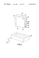
- FIG. 2 is a perspective drawing of a portable signaling unit which is included in the personal security and tracking system of FIG. 1;
- FIGS. 3A and 3B are perspective drawings of a remote alarm switch unit which is included in the personal security and tracking system of FIG. 1;
- FIG. 4 is a block diagram of the major circuit components in the remote alarm switch unit of FIGS. 3A and 3B;
- FIG. 5 is a block diagram of the major circuit components in the personal security and tracking system of FIG. 1 including a detailed block diagram of the portable signaling unit of FIG. 2;
- FIG. 6 is a block diagram of the major circuit components in an alternate embodiment of the personal security and tracking system of FIG. 1 including a detailed block diagram of the portable signaling unit of FIG. 2;
- FIG. 7 is a block diagram showing the functional components of a central dispatch station employed by the present invention.
- FIGS. 8A and 8B show various situations, alarm activation methods and the associated information received, displayed and stored at the central dispatch station.
- the personal security and tracking system generally includes a portable signaling unit 20 and a remote alarm switch unit 40 shown here in a configuration of a wristband. Either or both of portable signaling unit 20 and remote alarm switch unit 40 can be worn or carried by an individual 50 being monitored.
- the personal security and tracking system shown in FIG. 1 employs, as part of cellular telephone system 70 , wireless location technology, such as a cellular telephone Automatic Location Identification (ALI) system, in order to identify the origination location of an alarm signal generated by portable signaling unit 20 in response to a triggering of remote alarm switch unit 40 .
- wireless location technology such as a cellular telephone Automatic Location Identification (ALI) system
- ALI Automatic Location Identification
- other types of locating systems such as a Global Positioning System (GPS), LORAN-C, or GLONASS, may perform the function of providing accurate position coordinates and may be substituted therefor.
- GPS Global Positioning System
- LORAN-C LORAN-C
- GLONASS Global Positioning System
- a cellular telephone system 70 provides a means for data and voice communications between the portable signaling unit 20 and a central dispatch station 80 .
- the cellular telephone system 70 may be any conventional cellular telephone system. It should also be appreciated by one skilled in the art that other types of communication devices such as satellite transceivers or any other two-way wireless communication system may perform the function of the cellular telephone system 70 and may easily be substituted therefor. Hence, the present invention should not be construed as limited to a cellular telephone system.
- the portable security and tracking system also includes a central dispatch station 80 .
- the central dispatch station 80 is manned by one or more dispatch operators 82 and includes an intelligent telephone system 84 , one or more data modems 86 , a computer system 90 , and one or more display consoles 92 .
- the computer system 90 comprises means to store and access communications information, a user database, an emergency services database, map display information, and unit identifier and alarm status display information.
- the computer system 90 further comprises one or more data-to-voice switches and has remote activation capability, plotting algorithms, boundary monitoring alarm features, and the capability to store and retrieve historical data.
- display console 92 displays the alarm signal origination location, the user identification, and an alarm code, as described in FIG. 7.
- a number of suitable map programs incorporating many of these features are commercially available and suitable for use with the present invention.
- FIG. 2 shows a portable signaling unit 20 that includes a main power on-off keypad 22 .
- Local alarm push-button switches 24 a, 24 b, 24 c, etc. allow the use of the portable signaling unit 20 by campers, hikers, or skiers, etc., when the additional features of the remote alarm switch unit 40 may not be required.
- a cellular telephone antenna 26 is embodied in the casing of the signaling unit 20 .
- a GPS receiving antenna 30 could also be embodied in the outer part of the casing of signaling unit 20 when a GPS receiver is used for determining the location of the signaling unit.
- a speaker-microphone element 32 gives the central dispatch operator 82 the option to conduct two-way voice communications with the individual in distress.
- Portable signaling unit 20 can be manufactured in various configurations for attaching it securely to the individual 50 , including by use of a belt, belt clip, or carry strap. Another variation of the configuration could incorporate a sensor to detect if the portable signaling unit 20 was involuntarily removed from the individual and would automatically trigger an alarm signal to the central dispatch station.
- Remote alarm switch unit 40 further comprises a miniature radio transmitter having a built-in antenna 46 , a lithium battery 48 , an encoder circuit 58 , and an automatic switch circuit 44 that is activated if remote alarm switch unit 40 is removed from individual 50 by forceful or unauthorized means.
- a section of insulation material 52 e.g., non-electroconductive plastic, is provided so that the clasp portion 54 of the wristband can provide a closed circuit to the automatic alarm switch circuit 44 .
- These components enable remote alarm switch unit 40 to automatically generate a signal if the circuit is determined to be open (e.g., when the remote alarm switch unit 40 is unintentionally removed from the individual).
- Remote alarm switch unit 40 also comprises a timer circuit 56 , which enables remote alarm switch unit 40 to transmit a periodic signal so that portable signaling unit 20 can determine that remote alarm switch unit 40 is within the preset location range of portable signaling unit 20 (i.e., a “normal” condition: the portable signaling unit 20 is still being worn or carried by the individual).
- remote alarm switch unit 40 contains circuitry that enables remote alarm switch unit 40 to be in a non-transmitting mode when in a non-triggered state, except during transmission of the periodic signals. In this way, battery power is conserved, unlike where remote alarm switch unit 40 is continuously transmitting in the triggered state.
- the central dispatch station 80 will interpret an alarm signal generated by portable signaling unit 20 when portable signaling unit 20 fails to receive a periodic signal from remote alarm switch unit 40 as indicating that remote alarm switch unit 40 is not within the preset location range of portable signaling unit 20 . Since the central dispatch station 80 has not received an alarm indication that remote alarm switch unit 40 has been removed from the individual by forceful or unauthorized means, it must be that portable signaling unit 20 has been removed from the individual.
- FIG. 4 shows a functional block diagram of the circuits in the remote alarm switch unit 40 .
- the various manual alarm switches 42 a, 42 b, and 42 c are shown.
- automatic alarm switch circuit 44 encoder circuit 58 , timer circuit 56 , miniature radio transmitter having a built-in antenna 46 , and lithium battery 48 .
- FIG. 5 shows a system block diagram which includes portable signaling unit 20 , drop-in battery charger 36 , a cellular telephone system 70 with wireless location technology such as a cellular telephone Automatic Location Identification (ALI) system, remote alarm switch unit 40 , and central dispatch station 80 .
- Contained within the portable signaling unit 20 are 3 local alarm switches 24 a, 24 b, 24 c, a programmed unit serial identification code circuit 104 , a microcontroller 106 , a cellular telephone receiver 108 with a pre-assigned telephone number, a cellular telephone antenna 26 , and a cellular telephone transmitter 110 .
- 3 local alarm switches 24 a, 24 b, 24 c Contained within the portable signaling unit 20 are 3 local alarm switches 24 a, 24 b, 24 c, a programmed unit serial identification code circuit 104 , a microcontroller 106 , a cellular telephone receiver 108 with a pre-assigned telephone number, a cellular telephone antenna 26 , and a cellular telephone transmitter
- the cellular telephone circuit 110 also comprises a pre-programmed telephone number for the central dispatch station 80 , a redial counter, and alternate telephone numbers to provide for failsafe operation. Also included in the portable signaling unit are a data modem 112 , a data-to-voice switching circuit 114 , a remote alarm radio receiver with built-in antenna 116 , a decoder circuit 118 , a speaker-microphone element 32 , a rechargeable battery 120 , a low battery sensor circuit 122 , a missing pulse detector 124 , and a power-up switch circuit 126 .
- FIG. 6 shows an alternative system block diagram which incorporates the use of GPS satellite network 60 , a GPS receiving antenna 30 , a GPS receiving circuit 100 , and a position buffer circuit 102 , in association with the circuits described above with reference to FIG. 5 .
- the portable signaling unit 20 can be worn or carried by the user, preferably under the wearer's clothing so as to not be visible to a possible perpetrator.
- the portable signaling unit 20 is first put into service by an authorized person, parent, or guardian who enters a security code at the main power on/off key pad 22 .
- the portable signaling unit 20 is now in a stand-by mode so as to conserve battery power. In the stand-by mode only those circuits essential to sensing an alarm condition are powered on. These essential circuits include remote alarm radio receiver 116 decoder circuit 118 missing pulse detector 124 cellular telephone receiving circuit 108 data modem circuit 112 microcontroller 106 and a low battery sensing circuit 122 .
- the microcontroller 106 continuously polls the alarm inputs to detect a change in security conditions. It also commands and directs circuit operations.
- the data-to-voice switch circuit 114 remains in the data mode and cannot be switched to the voice mode until it receives the power up command. The remainder of the circuits remain off until an alarm input is detected.
- the portable signaling unit 20 is activated to the alarm mode when any one of the following conditions prevail:
- depressing any one of the manual push-button switches 24 a, 24 b, 24 c, etc. on the portable signaling unit 20 The selection of the proper manual push-button switches 24 a, 24 b, 24 c, etc. is related to various health conditions or a threat to the individual's personal safety, based on a pre-arranged agreement with the central dispatch station.
- depressing manual alarm push-button switch 24 c can mean “I'm okay, just checking in, as pre-arranged”
- depressing manual alarm push-button switch 24 b can mean “I am in need of medical assistance”
- depressing manual alarm push-button switch 24 a can mean “Help, my life is in danger!”
- depressing any one of the manual push-button switches 24 a, 24 b, 24 c , etc. on the portable signaling unit 20 sends a signal to microcontroller 106 and sets alarm input number 1 a, 1 b, 1 c, etc. corresponding to the manual switch that was depressed.
- depressing any one of the push-button switches 42 a, 42 b, or 42 c, etc. on the remote alarm switch unit 40 sends a pulse to the encoder circuit 58 .
- the encoder circuit 58 then sends an uniquely coded data pulse and a transmit “on” command to the miniature radio transmitter 46 .
- a radio frequency signal with the unique code denoting which manual switch was depressed, is sent from the remote alarm switch unit 40 to the portable signaling unit 20 .
- the signal is detected by the remote alarm radio receiver 116 and decoded by the decoder circuit 118 .
- Decoder 118 sets alarm input number 2 a, 2 b, or 2 c, etc. in the microcontroller 106 corresponding to the manual switch that was depressed in the remote alarm switch unit 40 . Coding and decoding the remote alarm switch unit 40 signal will prevent false triggering of the portable signaling unit 20 from other stray and random radio frequency sources.
- the automatic alarm switch circuit 44 is activated when, in this example, the wristband clasp assembly 54 is opened, or if the wristband is cut or broken. In either case, the automatic alarm switch circuit 44 senses that electrical continuity around the wristband is broken creating an open electrical circuit. The automatic alarm switch circuit 44 then sends a pulse to the encoder circuit 58 . The encoder circuit 58 sends a uniquely coded pulse and a transmit “on” command to the miniature radio transmitter 46 . In FIG. 5, a radio frequency signal, with the unique code denoting the automatic alarm switch circuit 44 activation, is sent to the portable signaling unit 20 . The signal is detected by remote alarm radio receiver 116 and decoded by decoder circuit 118 . Decoder 118 sets alarm input number 3 in the microcontroller 106 .
- a feature of the portable security and tracking system provides for detecting the separation of the portable signaling unit 20 from the remote alarm switch unit 40 .
- a scenario might be where the portable signaling unit 20 is removed from the individual 50 by a perpetrator and discarded and the remote alarm switch (in the form of a wristband for example) is untouched. Its operation is described as follows:
- the portable signaling unit 20 must receive a radio frequency signal from the remote alarm switch unit 40 at a predetermined time interval. A failure to receive this signal will activate the portable signaling unit 20 to transmit an alarm. This failure to receive the signal may be when the distance between the portable signaling unit 20 and the remote alarm switch unit 40 becomes too great to detect the signal or it may be caused by a battery or transmitter failure in the remote alarm switch unit 40 .
- the timer circuit 56 in remote alarm switch unit 40 sends a pulse to the encoder circuit 58 at a predetermined time interval, e.g., once every minute.
- the encoder circuit 58 sends a uniquely coded pulse and a short transmit “on” command to the miniature radio transmitter 46 .
- a radio frequency signal with a unique code denoting a timer circuit activation, is sent to the portable signaling unit 20 .
- the signal is detected by remote alarm radio receiver circuit 116 in the portable signaling unit 20 .
- the unique code is decoded by the decoder circuit 118 and sent to missing pulse detector circuit 124 . If missing pulse detector 124 fails to be reset within a predetermined time interval by the periodic signal, e.g., 1.5 minutes, then alarm input number 4 is set in microcontroller 106 .
- the separation distance at which the portable signaling unit 20 is activated is set by adjusting the power output of the miniature radio transmitter 46 in the remote alarm switch unit 40 .
- the low battery sensor circuit 122 is preset to allow a sufficient amount of remaining battery voltage to ensure reliable activation of the portable signaling unit 20 .
- alarm input flag number 5 is set in the microcontroller 106 .
- the central dispatch station operator 82 locates the subscriber information including the telephone number of portable signaling unit 20 in the computer system 90 database.
- the remote activation capability in the computer system 90 is then used to automatically dial the portable signaling unit 20 and transmit a cellular digital packet data (CDPD) transmission via the cellular telephone system 70 to the individual's portable signaling unit 20 .
- CDPD digital packet data
- FIG. 5 upon receiving the telephone CDPD transmission, cellular telephone receiver circuit 108 sends the received data through the data modem circuit 112 which sets alarm input number 6 in the microcontroller 106 .
- the microcontroller 106 Upon sensing any one of the above described alarm input conditions, the microcontroller 106 , then turns on the remainder of the circuits within the portable signaling unit 20 by activating power-up switch circuit 126 .
- the programmed unit identification code circuit 104 As shown in FIG. 5, the programmed unit identification code circuit 104 , the cellular telephone transmitter circuit 110 and the data-to-voice switching circuit 114 are turned on.
- FIG. 6 shows a variation of signaling unit 20 which incorporates a GPS receiver to determine the user's location.
- the GPS receiver 100 and the position buffer circuit 102 are also turned on upon sensing any one of the above described alarm input conditions.
- the microcontroller 106 commands the cellular telephone transmitter circuit 110 to automatically dial the central dispatch station 80 .
- the central dispatch station 80 receives the incoming signal and returns a CDPD transmission requesting the portable signaling unit 20 to send its data.
- the portable signaling unit 20 replies with a CDPD transmission consisting of its unit identification number and the alarm code.
- a GPS receiver is used to determine location
- a hierarchy of longitude and latitude coordinate data is also included in the CDPD transmission to the central dispatch station 80 .
- the microcontroller 106 when the cellular telephone transmitter circuit 110 is activated, the microcontroller 106 then sends a CDPD transmission consisting of its unit identification number and the alarm code. In the case where a GPS receiver is used to determine location, a hierarchy of longitude and latitude coordinate data is also included in the CDPD transmission to the central dispatch station 80 .
- the central dispatch station 80 receives the incoming CDPD transmission from the portable signaling unit 20 to the intelligent telephone system 84 via the cellular telephone system 70 .
- the cellular telephone system 70 provides Automatic Location Identification (ALI) information that gives the location of the origin of the cellular telephone transmissions.
- ALI Automatic Location Identification
- This technology has been developed by companies such as XYPOINT and The Associated Group (TruePositionTM), in response to a Federal Communications mandate (Report and Order 94-102) that requires E9-1-1 cellular telephone calls be located to within 125 meters (410 feet) of the origination point at a 67% or better accuracy rate.
- the signal is routed to a computer system 90 via one or more data modems 86 and is automatically verified by the computer system 90 .
- an acknowledgment CDPD transmission is sent back to the portable signaling unit 20 confirming that two-way communications has been established. Should an incoming cellular telephone call be a wrong number, the proper signal will not be detected, the cellular telephone transmitter circuit 110 will time out and will automatically hang up.
- the portable signaling unit 20 is automatically instructed by the computer system 90 to continue sending CDPD transmissions.
- FIG. 7 is a block diagram of the presently preferred embodiment of the central dispatch station 80 .
- the central dispatch station 80 generally comprises a conventional intelligent telephone system 84 connected to one or more data modems 86 then to a computer system 90 which in turn is connected to one or more display consoles 92 .
- the computer system 90 contains the communications information, user database, emergency services database, map display information, unit identifier and alarm status display information, one or more data-to-voice switches, remote activation capability, plotting algorithms, boundary monitoring alarm features, and has the capability to store and retrieve historical data.
- the computer system 90 can be networked so that incoming personal alarm messages may be allocated to the appropriate display consoles 92 to accommodate a high frequency of incoming calls.
- the computer system 90 and display consoles 92 may be any commercially available brand of microprocessor which includes video monitors.
- Incoming cellular calls from portable signaling unit 20 are automatically received and logged by the computer system 90 (via the intelligent telephone system 84 and one or more data modems 86 ).
- the CDPD transmissions along with the ALI information are decoded, validated and routed to display console(s) 92 .
- the display console(s) 92 continuously run a conventional digital map program.
- the map program is capable of (a) displaying detailed geographical area maps complete with street names and addresses, (b) real-time plotting of coordinates data at the appropriate position on the map (c) a user controlled zoom function, and (d) programmable display windows, symbols, and legend.
- a number of suitable map programs incorporating these features are commercially available.
- Computer system 90 processes and validates the received data.
- the portable signaling unit identification number is matched with the subscriber name in the database.
- the alarm code information is decoded and recorded.
- the ALI location data is analyzed for reliability and stored.
- the location of portable signaling unit 20 is displayed on one of the display consoles 92 in the form of a quickly recognizable symbol.
- the symbol can represent police, medical or any other key feature that may apply to the specific needs of the subscriber.
- the symbol appears superimposed on a digitized map on a computer monitor screen 92 at a position which corresponds to the location of the portable signaling unit 20 .
- Both the user identification data and alarm code are also displayed on the display console 92 .
- a data-to-voice switch capability in the computer system 90 allows the central dispatch operator 82 to conduct two-way communications with the person in distress via the portable signaling unit 20 .
- Various display capabilities are utilized to assist a dispatch operator 82 in locating the person in distress.
- the emergency services database allows a dispatch operator 82 to automatically dial the proper authorities and direct them to the exact location of the person to provide emergency assistance.
- the data is updated and transmitted at regular intervals until the connection is terminated by a dispatch operator 82 .
- An important feature of the personal security and tracking system is that when a low battery condition alarm is indicated from the portable signaling unit 20 , an alarm is activated at the central dispatch station 80 .
- a dispatch operator then notifies the designated person (e.g., parent or guardian) to service the battery.
- the central dispatch station can activate any portable signaling unit 20 to obtain an instant display of the current location of the individual carrying the portable signaling unit 20 .
- This activation would be on an “as needed” basis. For example, if a parent or guardian needed to determine the location of a lost person.
- the portable signaling unit 20 is automatically interrogated by the computer system 90 at predetermined time intervals. Should a CDPD transmission from the portable signaling unit yield data that is outside specified boundaries, the computer system 90 will activate an alarm to a dispatch operator 82 .
- situation 8 describes the self-check capability of the personal security and tracking system of FIG. 1 .
- the computer system 90 at the central dispatch station 80 can be programmed to automatically interrogate each portable signaling unit 20 at predetermined time intervals.
- the computer system 90 activates an alarm to a dispatch operator 82 if there is no response or if invalid data is received indicating a malfunction.
- the remote alarm switch unit 40 can be in the form of a wristband as described here or in the form of any other object, such as a broach, pendant, or keychain.
- the same arrangement of manual and automatically activated alarm switches could be incorporated in any design configuration.
- the portable signaling unit 20 can contain a GPS receiving circuit as described herein to provide more accurate location information in open areas where the cellular telephone ALI information may not be as precise.
- the portable signaling unit 20 can be configured such that it has all of the features of the remote alarm switch unit 40 in addition to its own features, with the exception of the distance-checking feature.
- the portable signaling unit 20 can also be configured with a small LCD display screen for the hearing impaired to receive messages from the central dispatch station.
Abstract
Description
Claims (48)
Priority Applications (7)
| Application Number | Priority Date | Filing Date | Title |
|---|---|---|---|
| US09/284,598 US6624754B1 (en) | 1998-01-20 | 1998-01-20 | Personal security and tracking system |
| US10/600,733 US20040014478A1 (en) | 1997-01-21 | 2003-06-20 | Personal security and tracking system |
| US10/628,094 US7038590B2 (en) | 1997-01-21 | 2003-07-25 | Personal security and tracking system |
| US11/404,206 US8149124B2 (en) | 1997-01-21 | 2006-04-14 | Personal security and tracking system |
| US13/404,977 US8466795B2 (en) | 1997-01-21 | 2012-02-24 | Personal security and tracking system |
| US13/905,054 US9235972B2 (en) | 1997-01-21 | 2013-05-29 | Personal security and tracking system |
| US14/674,150 US20150206418A1 (en) | 1997-01-21 | 2015-03-31 | Personal Security and Tracking System |
Applications Claiming Priority (2)
| Application Number | Priority Date | Filing Date | Title |
|---|---|---|---|
| PCT/US1998/000896 WO1998032105A2 (en) | 1997-01-20 | 1998-01-20 | Personal security and tracking system |
| US09/284,598 US6624754B1 (en) | 1998-01-20 | 1998-01-20 | Personal security and tracking system |
Related Parent Applications (3)
| Application Number | Title | Priority Date | Filing Date |
|---|---|---|---|
| US08/786,411 Continuation-In-Part US5742233A (en) | 1997-01-20 | 1997-01-21 | Personal security and tracking system |
| US08/881,054 Continuation-In-Part US6239700B1 (en) | 1997-01-20 | 1997-06-24 | Personal security and tracking system |
| PCT/US1998/000896 A-371-Of-International WO1998032105A2 (en) | 1997-01-20 | 1998-01-20 | Personal security and tracking system |
Related Child Applications (2)
| Application Number | Title | Priority Date | Filing Date |
|---|---|---|---|
| US10/600,733 Continuation US20040014478A1 (en) | 1997-01-21 | 2003-06-20 | Personal security and tracking system |
| US10/628,094 Continuation US7038590B2 (en) | 1997-01-21 | 2003-07-25 | Personal security and tracking system |
Publications (1)
| Publication Number | Publication Date |
|---|---|
| US6624754B1 true US6624754B1 (en) | 2003-09-23 |
Family
ID=28041532
Family Applications (4)
| Application Number | Title | Priority Date | Filing Date |
|---|---|---|---|
| US09/284,598 Expired - Lifetime US6624754B1 (en) | 1997-01-21 | 1998-01-20 | Personal security and tracking system |
| US10/600,733 Abandoned US20040014478A1 (en) | 1997-01-21 | 2003-06-20 | Personal security and tracking system |
| US10/628,094 Expired - Fee Related US7038590B2 (en) | 1997-01-21 | 2003-07-25 | Personal security and tracking system |
| US11/404,206 Expired - Fee Related US8149124B2 (en) | 1997-01-21 | 2006-04-14 | Personal security and tracking system |
Family Applications After (3)
| Application Number | Title | Priority Date | Filing Date |
|---|---|---|---|
| US10/600,733 Abandoned US20040014478A1 (en) | 1997-01-21 | 2003-06-20 | Personal security and tracking system |
| US10/628,094 Expired - Fee Related US7038590B2 (en) | 1997-01-21 | 2003-07-25 | Personal security and tracking system |
| US11/404,206 Expired - Fee Related US8149124B2 (en) | 1997-01-21 | 2006-04-14 | Personal security and tracking system |
Country Status (1)
| Country | Link |
|---|---|
| US (4) | US6624754B1 (en) |
Cited By (85)
| Publication number | Priority date | Publication date | Assignee | Title |
|---|---|---|---|---|
| US20020004412A1 (en) * | 2000-05-26 | 2002-01-10 | Waters John Deryk | Finding locally-relevant information in a document |
| US20020055361A1 (en) * | 2000-05-24 | 2002-05-09 | Mcdonnell James Thomas Edward | Location-based equipment control |
| US20030013463A1 (en) * | 2001-07-10 | 2003-01-16 | Yen Sen Hui | Smart all-purpose expert management system |
| US20030071734A1 (en) * | 2001-09-28 | 2003-04-17 | Vodin George M. | Method and apparatus for remote monitoring and control of a target group |
| US20030212311A1 (en) * | 2002-05-07 | 2003-11-13 | Medtronic Physio-Control Manufacturing Corp. | Therapy-delivering portable medical device capable of triggering and communicating with an alarm system |
| US20040038672A1 (en) * | 2002-04-01 | 2004-02-26 | Nguyen Hong Thi | Audio delivery of callerid information to a wireless communications device |
| US20040037403A1 (en) * | 2002-03-29 | 2004-02-26 | Koch Robert A. | Audio delivery of caller identification information |
| US20040037266A1 (en) * | 2002-06-21 | 2004-02-26 | Roberts Linda Ann | Internet call waiting messaging |
| US20040124979A1 (en) * | 2002-12-31 | 2004-07-01 | Medema Douglas K. | Communication between emergency medical device and safety agency |
| US20040172069A1 (en) * | 2003-02-28 | 2004-09-02 | Hakala Douglas T. | Recording information for emergency call by defibrillator apparatus |
| US20040178907A1 (en) * | 2001-07-13 | 2004-09-16 | Cordoba Juan Carlos | Alarm system for a portable device |
| US20040222891A1 (en) * | 2003-05-09 | 2004-11-11 | Gregory Ehlers | Proximity dead man interrupter, alarm and reporting system |
| US20050130670A1 (en) * | 2001-03-16 | 2005-06-16 | Gould Lawrence A. | Systems and methods for distributed processing of location information associated with emergency 911 wireless transmissions |
| US20050134455A1 (en) * | 2003-12-23 | 2005-06-23 | Valerie Binning | 911 Emergency light |
| US20050135570A1 (en) * | 2003-12-23 | 2005-06-23 | Valerie Binning | Caller controlled systems to suppress system to de-activate 911 indicator |
| US20050143048A1 (en) * | 2003-12-23 | 2005-06-30 | Valerie Binning | Activating home network devices when 911 indicator |
| US20050169439A1 (en) * | 2004-01-30 | 2005-08-04 | Valerie Binning | Automated third party call activated when 911 dialed |
| US20050169438A1 (en) * | 2004-01-30 | 2005-08-04 | Valerie Binning | System & methods for providing location signals/indicators when 911 dialed |
| US20050190750A1 (en) * | 2001-12-21 | 2005-09-01 | Bellsouth Intellectual Property Corporation | Voice over Network (VoN)/Voice Over Internet Protocol (VoIP) architect having hotline and optional tie line |
| US20050232243A1 (en) * | 2001-12-21 | 2005-10-20 | Maria Adamczyk | Voice-over Network (VoN)/voice-Over Internet Protocol (VoIP) architect using advance intelligent network alternatives |
| US20060029195A1 (en) * | 2004-08-18 | 2006-02-09 | Karen Mullis | Methods, apparatus and computer program products for message notification in a voice over internet protocol communication system |
| US20060027185A1 (en) * | 2000-12-26 | 2006-02-09 | Troxler Robert E | Large area position/proximity correction device with alarms using (D)GPS technology |
| US20060039367A1 (en) * | 2004-08-18 | 2006-02-23 | Bellsouth Intellectual Property Corporation | SIP-based session control |
| US20060041688A1 (en) * | 2004-08-18 | 2006-02-23 | Bellsouth Intellectual Property Corporation | SIP-based session control among a plurality of multimedia devices |
| US7005980B1 (en) * | 2002-08-15 | 2006-02-28 | Larry L. Schmidt | Personal rescue system |
| US20060047845A1 (en) * | 2004-08-31 | 2006-03-02 | Whited William Albert | Streaming gateway |
| US20060115057A1 (en) * | 2004-04-30 | 2006-06-01 | Donald Laliberte | Method and system for control of a voice/data communications device using a radio frequency component |
| US20060135214A1 (en) * | 2002-09-24 | 2006-06-22 | Bell South Intellectual Property Corporation | Apparatus and method for providing hands-free operation of a device |
| US20060239429A1 (en) * | 2003-04-29 | 2006-10-26 | Robert Koch | Privacy screening services |
| WO2006122416A1 (en) * | 2005-05-17 | 2006-11-23 | Surelinx Incorporated | Satellite-enabled remote location monitoring device with two-way distress signal capability |
| US20060261958A1 (en) * | 2005-04-25 | 2006-11-23 | Klein Hannah C | Identification band |
| US20070135187A1 (en) * | 2002-09-24 | 2007-06-14 | Kreiner Barrett M | Apparatus and method for providing hands-free operation of a device |
| US20070171047A1 (en) * | 2006-01-25 | 2007-07-26 | Goodman Gregory D | Device and system for locating and providing status of persons, animals or objects |
| US20070200716A1 (en) * | 2006-02-24 | 2007-08-30 | Concord Camera Corp. | Personal safety alarm device and method |
| US20070241261A1 (en) * | 2005-10-21 | 2007-10-18 | Wendt Barry M | Safety indicator and method |
| US20070243855A1 (en) * | 1997-01-21 | 2007-10-18 | Hoffman Resources Llc | Personal security and tracking system |
| US20070288263A1 (en) * | 2005-12-09 | 2007-12-13 | Valence Broadband, Inc. | Methods and systems for monitoring quality and performance at a healthcare facility |
| US20070290712A1 (en) * | 2006-06-19 | 2007-12-20 | Gomez Carlos I | Switch selectable terminator for differential and pseudo-differential signaling |
| US20080015903A1 (en) * | 2005-12-09 | 2008-01-17 | Valence Broadband, Inc. | Methods for refining patient, staff and visitor profiles used in monitoring quality and performance at a healthcare facility |
| US20080021731A1 (en) * | 2005-12-09 | 2008-01-24 | Valence Broadband, Inc. | Methods and systems for monitoring patient support exiting and initiating response |
| US7391761B1 (en) | 2001-12-21 | 2008-06-24 | At&T Delaware Intellectual Property, Inc. | System and method for voice over internet protocol using a standard telephone system |
| US7437167B2 (en) | 2002-12-10 | 2008-10-14 | Steve Gene Kartchner | Apparatus, system, and method for locating a transceiver using RF communications and radio services |
| US20080262780A1 (en) * | 2002-10-11 | 2008-10-23 | Troxler Electronic Laboratories, Inc. | Paving-Related Measuring Device Incorporating a Computer Device and Communication Element Therebetween and Associated Method |
| US7477903B2 (en) | 2000-05-20 | 2009-01-13 | Hewlett-Packard Development Company, L.P. | Obtaining location updates about a mobile entity for use in a location-sensitive application |
| US20090016500A1 (en) * | 2002-06-21 | 2009-01-15 | Linda Ann Roberts | Methods, Systems, and Products for Caller Control of Internet Call Waiting |
| US20090044334A1 (en) * | 2007-08-13 | 2009-02-19 | Valence Broadband, Inc. | Automatically adjusting patient platform support height in response to patient related events |
| US20090044332A1 (en) * | 2007-08-13 | 2009-02-19 | Valence Broadband, Inc. | Height adjustable patient support platforms |
| US20090119843A1 (en) * | 2007-11-12 | 2009-05-14 | Valence Broadband, Inc. | Monitoring patient support exiting and initiating response |
| US7571468B1 (en) | 2004-04-06 | 2009-08-04 | Sun Microsystems, Inc. | Personal authorisation device |
| US20090322513A1 (en) * | 2008-06-27 | 2009-12-31 | Franklin Dun-Jen Hwang | Medical emergency alert system and method |
| US20100029246A1 (en) * | 2004-01-30 | 2010-02-04 | Valerie Binning | Methods, Systems & Products for Emergency Location |
| US7761310B2 (en) | 2005-12-09 | 2010-07-20 | Samarion, Inc. | Methods and systems for monitoring quality and performance at a healthcare facility |
| US7783013B2 (en) | 2004-04-30 | 2010-08-24 | At&T Intellectual Property I, L.P. | Method and system for routing emergency communications |
| US7786874B2 (en) | 2005-12-09 | 2010-08-31 | Samarion, Inc. | Methods for refining patient, staff and visitor profiles used in monitoring quality and performance at a healthcare facility |
| US7848905B2 (en) * | 2000-12-26 | 2010-12-07 | Troxler Electronic Laboratories, Inc. | Methods, systems, and computer program products for locating and tracking objects |
| US20100311388A1 (en) * | 2009-02-03 | 2010-12-09 | Integrity Tracking, Llc | Communications method |
| US20100309046A1 (en) * | 2009-02-03 | 2010-12-09 | Integrity Tracking, Llc | Communications method |
| US20110080262A1 (en) * | 2005-06-03 | 2011-04-07 | Richardson Mark A | Location finder system |
| ITRM20100402A1 (en) * | 2010-07-20 | 2012-01-21 | Yopo Bvba | METHOD AND MONITORING AND CONTROL SYSTEM FOR PERSONAL SAFETY WITH DELEGATION OF REMOTE USE OF INPUT AND OUTPUT DEVICES ON POCKET DEVICE |
| US20120105226A1 (en) * | 2009-05-16 | 2012-05-03 | Cynthia Bourdeau | Object locating system |
| US8466795B2 (en) | 1997-01-21 | 2013-06-18 | Pragmatus Mobile LLC | Personal security and tracking system |
| US20130214923A1 (en) * | 2010-11-05 | 2013-08-22 | Seniors Wellbeing Pty Ltd | Immobility Monitoring System |
| US8537821B2 (en) | 2004-05-27 | 2013-09-17 | Shoretel, Inc. | Methods, systems, and products for emergency communications |
| US8620625B2 (en) | 2010-07-30 | 2013-12-31 | Hill-Rom Services, Inc. | Above bed sensor |
| US8907287B2 (en) | 2010-12-01 | 2014-12-09 | Hill-Rom Services, Inc. | Patient monitoring system |
| US9031581B1 (en) | 2005-04-04 | 2015-05-12 | X One, Inc. | Apparatus and method for obtaining content on a cellular wireless device based on proximity to other wireless devices |
| US9148500B2 (en) | 2007-01-04 | 2015-09-29 | At&T Intellectual Property I, L.P. | Command prefix for voice commands |
| US9295390B2 (en) | 2012-03-02 | 2016-03-29 | Hill-Rom Services, Inc. | Facial recognition based monitoring systems and methods |
| US9311804B2 (en) | 2014-04-11 | 2016-04-12 | Hill-Rom Services, Inc. | Patient-need prediction system |
| US9589448B1 (en) | 2015-12-08 | 2017-03-07 | Micro Apps Group Inventions, LLC | Autonomous safety and security device on an unmanned platform under command and control of a cellular phone |
| US20170251349A1 (en) * | 2015-01-28 | 2017-08-31 | Arati P. Singh | Portable device for indicating emergecny events |
| EP3255619A1 (en) | 2016-06-10 | 2017-12-13 | Micro APPS Group Inventions LLC | Wireless personal safety device |
| US10096232B1 (en) | 2017-10-26 | 2018-10-09 | USA Innovations, Inc. | Portable security alarm device |
| US10111079B2 (en) | 2016-07-06 | 2018-10-23 | Katana Safety, Inc. | Mobile device accessory with separate component for control or alert |
| US10223521B1 (en) * | 2015-10-05 | 2019-03-05 | Jpmorgan Chase Bank, N.A. | Systems and methods for location determination using radio frequency tags |
| US20190077003A1 (en) * | 2016-03-01 | 2019-03-14 | Husqvarna Ab | Wearable apparatus and system for use with outdoor power equipment |
| US10477008B2 (en) | 2015-01-23 | 2019-11-12 | Smartwatcher Technologies Ag | Personal emergency triggering, notification and communication for smartwatches |
| US10659946B2 (en) | 2016-07-06 | 2020-05-19 | Katana Safety, Inc. | Mobile device attachment with user activated alarm |
| US10739133B1 (en) | 2003-06-17 | 2020-08-11 | Troxler Electronic Laboratories, Inc. | Method for determining a surface characteristic of a roadway using infrared radiation and an imaging device |
| US10948476B2 (en) | 2000-12-26 | 2021-03-16 | Troxler Electronic Laboratories, Inc. | Methods, systems, and computer program products for locating and tracking objects |
| US11295595B2 (en) * | 2019-12-20 | 2022-04-05 | Inventis Technology Pty Limited | Emergency alert system |
| US11357454B2 (en) * | 2018-05-01 | 2022-06-14 | Fantastic Co., Ltd. | Nursing care recipient watching support system |
| US11436907B2 (en) | 2011-06-22 | 2022-09-06 | Thinkware Corporation | Safety service system and method thereof |
| US11488466B2 (en) | 2018-11-26 | 2022-11-01 | Ray P. Lewis | Wearable personal or public safety device |
| US11900778B1 (en) | 2023-03-29 | 2024-02-13 | Micro Apps Group Inventions, LLC | System for improving safety in schools |
Families Citing this family (129)
| Publication number | Priority date | Publication date | Assignee | Title |
|---|---|---|---|---|
| US7198190B2 (en) * | 1997-03-12 | 2007-04-03 | Dodge Juhan | Identification device having reusable transponder |
| AU7584298A (en) * | 1997-05-21 | 1998-12-11 | E.S.P. Communications, Inc. | System, method and apparatus for "caller only" initiated two-way wireless communication with caller generated billing |
| US6560461B1 (en) * | 1997-08-04 | 2003-05-06 | Mundi Fomukong | Authorized location reporting paging system |
| US7942313B1 (en) * | 1998-10-09 | 2011-05-17 | Diebold, Incorporated | Automated banking machine system and monitoring method |
| US7310509B2 (en) * | 2000-04-17 | 2007-12-18 | Decarta Inc. | Software and protocol structure for an automated user notification system |
| US6356841B1 (en) | 1999-12-29 | 2002-03-12 | Bellsouth Intellectual Property Corporation | G.P.S. management system |
| US6868074B1 (en) * | 2000-03-30 | 2005-03-15 | Mci, Inc. | Mobile data device and method of locating mobile data device |
| GB0021544D0 (en) * | 2000-09-01 | 2000-10-18 | Nokia Networks Oy | Broadcasting in a communication system |
| JP2003046614A (en) * | 2001-07-27 | 2003-02-14 | Toshiba Corp | Mobile wireless terminal |
| KR100463435B1 (en) * | 2002-02-27 | 2004-12-23 | 최용학 | Method of membership protection using mobile communication device |
| US20040214568A1 (en) * | 2002-03-27 | 2004-10-28 | Uraxs Communications, Inc. | Remote UltraWide Band communication system with short messaging and other functions |
| US20030203730A1 (en) * | 2002-04-11 | 2003-10-30 | Dadong Wan | Location-based remote monitoring |
| AU2003237296A1 (en) * | 2002-05-31 | 2003-12-19 | Spatial Wireless, Inc. | Method and system for providing location information of a mobile station |
| GB0218076D0 (en) * | 2002-08-03 | 2002-09-11 | Kingston John E | Alarm system |
| US7184744B1 (en) * | 2002-10-10 | 2007-02-27 | Itt Manufacturing Enterprises, Inc. | GPS enabled emergency messaging system |
| WO2004074778A1 (en) | 2003-02-14 | 2004-09-02 | Networks In Motion, Inc. | Method and system for saving and retrieving spatial related information |
| US7359713B1 (en) * | 2003-02-28 | 2008-04-15 | Trimble Navigation Limited | Battery consumption optimization for mobile users |
| US7119716B2 (en) * | 2003-05-28 | 2006-10-10 | Legalview Assets, Limited | Response systems and methods for notification systems for modifying future notifications |
| US7428417B2 (en) * | 2003-09-26 | 2008-09-23 | Siemens Communications, Inc. | System and method for presence perimeter rule downloading |
| US8825194B2 (en) * | 2003-12-18 | 2014-09-02 | International Business Machines Corporation | Global positioning system location information for an automated data storage library |
| US20050138071A1 (en) * | 2003-12-18 | 2005-06-23 | International Business Machines Corporation | Accurate time information for the operation of an automated data storage library |
| US7672677B2 (en) * | 2004-01-16 | 2010-03-02 | Compasscom Software Corporation | Method and system to transfer and to display location information about an object |
| KR200353115Y1 (en) * | 2004-03-17 | 2004-06-22 | 석찬복 | lantern for army |
| CA2475823C (en) * | 2004-07-16 | 2016-03-22 | Petsmobility Network, Inc. | Pet communication system |
| US7088235B1 (en) * | 2004-08-20 | 2006-08-08 | Carricut Lee M | Method and apparatus for retrofitting a patient call system |
| US20060105782A1 (en) * | 2004-11-12 | 2006-05-18 | Cameron Brock | Method and apparatus for controlling a geo-tracking device |
| US7598855B2 (en) | 2005-02-01 | 2009-10-06 | Location Based Technologies, Inc. | Apparatus and method for locating individuals and objects using tracking devices |
| US20070229350A1 (en) * | 2005-02-01 | 2007-10-04 | Scalisi Joseph F | Apparatus and Method for Providing Location Information on Individuals and Objects using Tracking Devices |
| US7728724B1 (en) * | 2005-02-01 | 2010-06-01 | Location Based Technologies, Inc. | System for locating individuals and objects |
| EP1877990A4 (en) | 2005-04-06 | 2009-11-04 | Omnilink Systems Inc | System and method for tracking monitoring, collecting, reporting and communicating with the movement of individuals |
| WO2006122004A1 (en) | 2005-05-06 | 2006-11-16 | Omnilink Systems, Inc. | System and method of tracking the movement of individuals and assets |
| GB2428542A (en) * | 2005-07-19 | 2007-01-31 | Alexander Taylor | Wristband locating device |
| US7330122B2 (en) | 2005-08-10 | 2008-02-12 | Remotemdx, Inc. | Remote tracking and communication device |
| US20070042727A1 (en) * | 2005-08-16 | 2007-02-22 | Arinc Inc. | Systems and methods for voice and data communication |
| US20080036612A1 (en) * | 2005-08-24 | 2008-02-14 | Koslow Chad C | System and Method for Tracking, Locating, and Identifying Known Sex Offenders |
| US8520069B2 (en) * | 2005-09-16 | 2013-08-27 | Digital Ally, Inc. | Vehicle-mounted video system with distributed processing |
| JP2007093433A (en) * | 2005-09-29 | 2007-04-12 | Hitachi Ltd | Detector for motion of pedestrian |
| US7525425B2 (en) | 2006-01-20 | 2009-04-28 | Perdiem Llc | System and method for defining an event based on relationship between an object location and a user-defined zone |
| WO2007073470A2 (en) | 2005-12-23 | 2007-06-28 | Perdiem, Llc | System and method for defining an event based on a relationship between an object location and a user-defined zone |
| US7619533B2 (en) * | 2006-01-07 | 2009-11-17 | Streetime Technologies Llc | Method and apparatus for monitoring persons |
| BRPI0600472B1 (en) * | 2006-02-06 | 2019-04-02 | Samara Nehmi Nagy | HUMAN, ANIMAL OR OBJECT TRACKING SYSTEM |
| US8165562B2 (en) * | 2006-03-20 | 2012-04-24 | Rave Wireless, Inc. | Personalized message escrow |
| US8126424B2 (en) * | 2006-03-20 | 2012-02-28 | Rave Wireless, Inc. | Personalized message escrow with graphical route representation |
| US20070218895A1 (en) | 2006-03-20 | 2007-09-20 | Rave Wireless, Inc. | Personal security system |
| US20070236347A1 (en) * | 2006-03-28 | 2007-10-11 | Michael Francois | Locating apparatus for battery operated electronic devices |
| US8302856B1 (en) | 2006-07-07 | 2012-11-06 | Diebold, Incorporated | Automated banking machine system and monitoring method |
| US7737841B2 (en) | 2006-07-14 | 2010-06-15 | Remotemdx | Alarm and alarm management system for remote tracking devices |
| US8797210B2 (en) | 2006-07-14 | 2014-08-05 | Securealert, Inc. | Remote tracking device and a system and method for two-way voice communication between the device and a monitoring center |
| US20080125040A1 (en) * | 2006-11-29 | 2008-05-29 | Apple Computer, Inc. | Location discovery using bluetooth |
| US8761718B2 (en) * | 2006-11-30 | 2014-06-24 | West Corporation | Verification of communications network-derived location information |
| US8477035B2 (en) * | 2007-02-28 | 2013-07-02 | Alcatel Lucent | Security system triggered by heart rate detection |
| US7930927B2 (en) * | 2007-03-06 | 2011-04-26 | Bi Incorporated | Transdermal portable alcohol monitor and methods for using such |
| US20100156626A1 (en) * | 2007-03-20 | 2010-06-24 | Brian Story | Remote Telemetric Panic and Service Apparatus |
| US20080316022A1 (en) * | 2007-03-26 | 2008-12-25 | Bi Incorporated | Beacon Based Tracking Devices and Methods for Using Such |
| US8224355B2 (en) * | 2007-11-06 | 2012-07-17 | Location Based Technologies Inc. | System and method for improved communication bandwidth utilization when monitoring location information |
| US9111189B2 (en) * | 2007-10-31 | 2015-08-18 | Location Based Technologies, Inc. | Apparatus and method for manufacturing an electronic package |
| US8102256B2 (en) | 2008-01-06 | 2012-01-24 | Location Based Technologies Inc. | Apparatus and method for determining location and tracking coordinates of a tracking device |
| US8497774B2 (en) | 2007-04-05 | 2013-07-30 | Location Based Technologies Inc. | Apparatus and method for adjusting refresh rate of location coordinates of a tracking device |
| US8774827B2 (en) | 2007-04-05 | 2014-07-08 | Location Based Technologies, Inc. | Apparatus and method for generating position fix of a tracking device in accordance with a subscriber service usage profile to conserve tracking device power |
| US8244468B2 (en) * | 2007-11-06 | 2012-08-14 | Location Based Technology Inc. | System and method for creating and managing a personalized web interface for monitoring location information on individuals and objects using tracking devices |
| US8115621B2 (en) * | 2007-05-01 | 2012-02-14 | Yoganand Rajala | Device for tracking the movement of individuals or objects |
| US7538724B1 (en) * | 2007-06-15 | 2009-05-26 | Itt Manufacturing Enterprises, Inc. | Method and system for relative tracking |
| US7768394B2 (en) * | 2007-07-02 | 2010-08-03 | Honeywell International Inc. | System and apparatus for integrated location detection and wireless communications |
| WO2009012411A1 (en) * | 2007-07-18 | 2009-01-22 | Sky Detective, Inc. | Gang tracker |
| US20090042534A1 (en) * | 2007-08-08 | 2009-02-12 | Janne Levanen | Personal security tracking system and method |
| US7825794B2 (en) * | 2007-08-10 | 2010-11-02 | Integrity Tracking, Llc | Alzheimer's patient tracking system |
| US8004399B2 (en) * | 2007-10-11 | 2011-08-23 | Honeywell International Inc. | Life safety device with integrated Wi-Fi and GPS capability |
| US8654974B2 (en) * | 2007-10-18 | 2014-02-18 | Location Based Technologies, Inc. | Apparatus and method to provide secure communication over an insecure communication channel for location information using tracking devices |
| US20090121931A1 (en) * | 2007-11-12 | 2009-05-14 | Katz Daniel A | Wrist Worn Communication Device coupled with Antenna Extendable by the Arm |
| US20090167525A1 (en) * | 2008-01-02 | 2009-07-02 | Christopher Gilboy | System, method and apparatus for avoiding loss of portable devices |
| US8258942B1 (en) | 2008-01-24 | 2012-09-04 | Cellular Tracking Technologies, LLC | Lightweight portable tracking device |
| US8232876B2 (en) | 2008-03-07 | 2012-07-31 | Securealert, Inc. | System and method for monitoring individuals using a beacon and intelligent remote tracking device |
| US8031078B1 (en) | 2008-09-03 | 2011-10-04 | Liestman Richard E | Key chain holder with clock and alarm |
| US8461983B2 (en) * | 2008-09-13 | 2013-06-11 | Michele McCauley | Personal security device |
| AU2008101004A4 (en) * | 2008-10-12 | 2008-11-27 | Yeoman, Patrick John Mr | Triga psd |
| WO2010047887A2 (en) * | 2008-10-24 | 2010-04-29 | Procon , Inc. | Apparatus and method for testing emergency locator beacons |
| US8503972B2 (en) * | 2008-10-30 | 2013-08-06 | Digital Ally, Inc. | Multi-functional remote monitoring system |
| US8493219B2 (en) * | 2008-11-14 | 2013-07-23 | Bi Incorporated | Systems and methods for adaptive monitoring and tracking of a target having a learning period |
| KR20100060783A (en) * | 2008-11-28 | 2010-06-07 | 삼성전자주식회사 | System and method for sos rescue and prevention of crime |
| US8270938B2 (en) * | 2009-02-03 | 2012-09-18 | Integrity Tracking, Llc | Managing battery power for mobile emergency communication device |
| US8086250B2 (en) * | 2009-02-03 | 2011-12-27 | Integrity Tracking, Llc | Communications method |
| US8441356B1 (en) * | 2009-02-16 | 2013-05-14 | Handhold Adaptive, LLC | Methods for remote assistance of disabled persons |
| US8657744B2 (en) | 2009-03-23 | 2014-02-25 | Bi Incorporated | Systems and methods for transdermal secretion detection |
| US20100311387A1 (en) * | 2009-06-05 | 2010-12-09 | Melinda Marie Cameron | Panic activated locator (p.a.l.) |
| US8351895B2 (en) * | 2009-09-04 | 2013-01-08 | Zomm, Llc | Wireless security device and method to place emergency calls |
| US9355548B2 (en) | 2009-12-03 | 2016-05-31 | Bi Incorporated | Systems and methods for contact avoidance |
| US8576065B2 (en) * | 2009-12-03 | 2013-11-05 | Bi Incorporated | Systems and methods for variable collision avoidance |
| US8629776B2 (en) * | 2009-12-03 | 2014-01-14 | Bi Incorporated | Systems and methods for disrupting criminal activity |
| US8489113B2 (en) * | 2010-02-09 | 2013-07-16 | Omnilink Systems, Inc. | Method and system for tracking, monitoring and/or charging tracking devices including wireless energy transfer features |
| US20110223880A1 (en) * | 2010-03-02 | 2011-09-15 | Sosy Technologies Stu, Inc. | Optimized Predictive Emergency Notification for Vehicles While in No Cellular Coverage Area |
| US8514070B2 (en) | 2010-04-07 | 2013-08-20 | Securealert, Inc. | Tracking device incorporating enhanced security mounting strap |
| US20110291801A1 (en) * | 2010-06-01 | 2011-12-01 | Sommer William R | Personal warning device |
| US8525688B2 (en) * | 2011-01-10 | 2013-09-03 | Palm, Inc. | Proximity detection alarm for an inductively charged mobile computing device |
| WO2012140155A1 (en) * | 2011-04-14 | 2012-10-18 | Novo Nordisk A/S | Fatty acid acylated amino acids for oral peptide delivery |
| US8308680B1 (en) * | 2011-04-26 | 2012-11-13 | Medtronic Minimed, Inc. | Selective alarms for an infusion device |
| US8990709B2 (en) * | 2011-07-08 | 2015-03-24 | Net Power And Light, Inc. | Method and system for representing audiences in ensemble experiences |
| US20130109427A1 (en) * | 2011-11-02 | 2013-05-02 | George Matus | Individual Security Through Mobile Device Notifications |
| EP2807455A4 (en) | 2012-01-26 | 2015-08-12 | Telecomm Systems Inc | Natural navigational guidance |
| US9215578B2 (en) | 2012-01-27 | 2015-12-15 | Omnilink Systems, Inc. | Monitoring systems and methods |
| US8930139B2 (en) | 2012-06-21 | 2015-01-06 | Telecommunication Systems, Inc. | Dynamically varied map labeling |
| US9019431B2 (en) | 2012-09-28 | 2015-04-28 | Digital Ally, Inc. | Portable video and imaging system |
| US10272848B2 (en) | 2012-09-28 | 2019-04-30 | Digital Ally, Inc. | Mobile video and imaging system |
| US9180063B2 (en) | 2012-12-04 | 2015-11-10 | Scott & White Healthcare (Swh) | Systems and methods for assisted ambulation |
| US9123244B2 (en) * | 2013-03-15 | 2015-09-01 | Denso International America, Inc. | Vehicle tracking of personal devices with response system |
| US9958228B2 (en) | 2013-04-01 | 2018-05-01 | Yardarm Technologies, Inc. | Telematics sensors and camera activation in connection with firearm activity |
| US10390732B2 (en) | 2013-08-14 | 2019-08-27 | Digital Ally, Inc. | Breath analyzer, system, and computer program for authenticating, preserving, and presenting breath analysis data |
| US10075681B2 (en) | 2013-08-14 | 2018-09-11 | Digital Ally, Inc. | Dual lens camera unit |
| US9253452B2 (en) | 2013-08-14 | 2016-02-02 | Digital Ally, Inc. | Computer program, method, and system for managing multiple data recording devices |
| US9159371B2 (en) | 2013-08-14 | 2015-10-13 | Digital Ally, Inc. | Forensic video recording with presence detection |
| US9508241B2 (en) * | 2013-09-11 | 2016-11-29 | Christopher DePascale | Wearable personal locator device with removal indicator |
| US9232379B2 (en) * | 2013-10-31 | 2016-01-05 | Kenneth Margon | Notification system using a duplicate start record |
| TWI606342B (en) | 2014-10-20 | 2017-11-21 | 愛克勝企業公司 | Systems and methods for distributed control |
| WO2016100356A1 (en) | 2014-12-15 | 2016-06-23 | Yardarm Technologies, Inc. | Camera activation in response to firearm activity |
| CN107148579A (en) * | 2015-05-15 | 2017-09-08 | 保罗·格拉夫斯马 | Enhanced mobile personal emergency response system and application method |
| US9841259B2 (en) | 2015-05-26 | 2017-12-12 | Digital Ally, Inc. | Wirelessly conducted electronic weapon |
| US9251686B1 (en) | 2015-06-01 | 2016-02-02 | iSHADOW Technology Inc. | Personal safety tracking using an apparatus comprising multiple sensors |
| US10013883B2 (en) | 2015-06-22 | 2018-07-03 | Digital Ally, Inc. | Tracking and analysis of drivers within a fleet of vehicles |
| CH711245A2 (en) * | 2015-06-25 | 2016-12-30 | Geosatis Sa | Electronic monitoring system and method. |
| US10192277B2 (en) | 2015-07-14 | 2019-01-29 | Axon Enterprise, Inc. | Systems and methods for generating an audit trail for auditable devices |
| WO2017136646A1 (en) | 2016-02-05 | 2017-08-10 | Digital Ally, Inc. | Comprehensive video collection and storage |
| US10332381B2 (en) * | 2016-04-05 | 2019-06-25 | Tech Traks, Inc. | Intelligent asset detachment sensor system |
| US10521675B2 (en) | 2016-09-19 | 2019-12-31 | Digital Ally, Inc. | Systems and methods of legibly capturing vehicle markings |
| US10911725B2 (en) | 2017-03-09 | 2021-02-02 | Digital Ally, Inc. | System for automatically triggering a recording |
| US11024137B2 (en) | 2018-08-08 | 2021-06-01 | Digital Ally, Inc. | Remote video triggering and tagging |
| CN110376626A (en) * | 2019-06-17 | 2019-10-25 | 楼云吟 | A kind of wearable positioning and tracking device based on Radio Frequency Identification Technology |
| US11393319B1 (en) | 2019-07-29 | 2022-07-19 | REMI Device Company | Personal tracking and communication system and method |
| US11701007B2 (en) | 2020-08-28 | 2023-07-18 | Bi Incorporated | Systems and methods for biometric tamper detection |
| US11665507B2 (en) | 2020-09-15 | 2023-05-30 | Bi Incorporated | Systems and methods for intercept directing in a monitoring system |
| US11950017B2 (en) | 2022-05-17 | 2024-04-02 | Digital Ally, Inc. | Redundant mobile video recording |
Citations (8)
| Publication number | Priority date | Publication date | Assignee | Title |
|---|---|---|---|---|
| US5125103A (en) * | 1990-04-30 | 1992-06-23 | Motorola, Inc. | Automatic control channel acquisition method and apparatus in a trunked communication system |
| US5410739A (en) * | 1992-09-29 | 1995-04-25 | The Titan Corporation | Variable data message communication over voice communication channel |
| US5416468A (en) * | 1993-10-29 | 1995-05-16 | Motorola, Inc. | Two-tiered system and method for remote monitoring |
| US5554993A (en) * | 1994-01-04 | 1996-09-10 | Panasonic Technologies, Inc. | Global position determining system and method |
| US5650770A (en) * | 1994-10-27 | 1997-07-22 | Schlager; Dan | Self-locating remote monitoring systems |
| US5742233A (en) * | 1997-01-21 | 1998-04-21 | Hoffman Resources, Llc | Personal security and tracking system |
| US5959529A (en) * | 1997-03-07 | 1999-09-28 | Kail, Iv; Karl A. | Reprogrammable remote sensor monitoring system |
| US6239700B1 (en) * | 1997-01-21 | 2001-05-29 | Hoffman Resources, Inc. | Personal security and tracking system |
Family Cites Families (29)
| Publication number | Priority date | Publication date | Assignee | Title |
|---|---|---|---|---|
| US4965586A (en) * | 1984-08-16 | 1990-10-23 | Geostar Corporation | Position determination and message transfer system employing satellites and stored terrain map |
| US4839656A (en) * | 1984-08-16 | 1989-06-13 | Geostar Corporation | Position determination and message transfer system employing satellites and stored terrain map |
| US4744083A (en) * | 1984-09-14 | 1988-05-10 | Geostar Corporation | Satellite-based position determining and message transfer system with monitoring of link quality |
| US5245314A (en) * | 1985-09-18 | 1993-09-14 | Kah Jr Carl L C | Location monitoring system |
| US4819860A (en) * | 1986-01-09 | 1989-04-11 | Lloyd D. Lillie | Wrist-mounted vital functions monitor and emergency locator |
| US4818998A (en) * | 1986-03-31 | 1989-04-04 | Lo-Jack Corporation | Method of and system and apparatus for locating and/or tracking stolen or missing vehicles and the like |
| US4694284A (en) * | 1986-04-14 | 1987-09-15 | Serge Leveille | Abduction-preventing collar |
| US4885571A (en) * | 1986-04-15 | 1989-12-05 | B. I. Incorperated | Tag for use with personnel monitoring system |
| US4952913A (en) * | 1986-04-15 | 1990-08-28 | B. I. Incorporated | Tag for use with personnel monitoring system |
| US4799062A (en) * | 1987-04-27 | 1989-01-17 | Axonn Corporation | Radio position determination method and apparatus |
| US5027314A (en) * | 1988-03-17 | 1991-06-25 | United Manufacturing Co., Inc. | Apparatus and method for position reporting |
| US4918432A (en) * | 1988-09-27 | 1990-04-17 | B. I. Incorporated | House arrest monitoring system |
| US5021794A (en) * | 1989-08-15 | 1991-06-04 | Lawrence Robert A | Personal emergency locator system |
| US5225809A (en) * | 1990-12-24 | 1993-07-06 | Mayday U.S.A. Inc. | Personal security system and apparatus therefor |
| US5225842A (en) * | 1991-05-09 | 1993-07-06 | Navsys Corporation | Vehicle tracking system employing global positioning system (gps) satellites |
| US5266944A (en) * | 1991-06-26 | 1993-11-30 | Bodyguard Technologies, Inc. | Electronic system and method for monitoring abusers for compliance with a protective order |
| US5196825A (en) * | 1991-12-16 | 1993-03-23 | Young James T | Personal security apparatus |
| US5334974A (en) * | 1992-02-06 | 1994-08-02 | Simms James R | Personal security system |
| US5515419A (en) * | 1992-06-01 | 1996-05-07 | Trackmobile | Tracking system and method for tracking a movable object carrying a cellular phone unit, and integrated personal protection system incorporating the tracking system |
| US5461390A (en) * | 1994-05-27 | 1995-10-24 | At&T Ipm Corp. | Locator device useful for house arrest and stalker detection |
| US5559520A (en) * | 1994-09-26 | 1996-09-24 | Lucent Technologies Inc. | Wireless information system for acquiring location related information |
| US6072396A (en) * | 1994-12-30 | 2000-06-06 | Advanced Business Sciences | Apparatus and method for continuous electronic monitoring and tracking of individuals |
| US5797091A (en) * | 1995-03-07 | 1998-08-18 | Xypoint Corporation | Personal communication system and method of use |
| US6002363A (en) * | 1996-03-08 | 1999-12-14 | Snaptrack, Inc. | Combined GPS positioning system and communications system utilizing shared circuitry |
| US5874914A (en) * | 1995-10-09 | 1999-02-23 | Snaptrack, Inc. | GPS receiver utilizing a communication link |
| US5731757A (en) * | 1996-08-19 | 1998-03-24 | Pro Tech Monitoring, Inc. | Portable tracking apparatus for continuous position determination of criminal offenders and victims |
| US6624754B1 (en) * | 1998-01-20 | 2003-09-23 | Hoffman Resources Llc | Personal security and tracking system |
| US6188939B1 (en) * | 1997-08-18 | 2001-02-13 | The Texas A&M University System | Advanced law enforcement and response technology |
| US5999124A (en) * | 1998-04-22 | 1999-12-07 | Snaptrack, Inc, | Satellite positioning system augmentation with wireless communication signals |
-
1998
- 1998-01-20 US US09/284,598 patent/US6624754B1/en not_active Expired - Lifetime
-
2003
- 2003-06-20 US US10/600,733 patent/US20040014478A1/en not_active Abandoned
- 2003-07-25 US US10/628,094 patent/US7038590B2/en not_active Expired - Fee Related
-
2006
- 2006-04-14 US US11/404,206 patent/US8149124B2/en not_active Expired - Fee Related
Patent Citations (8)
| Publication number | Priority date | Publication date | Assignee | Title |
|---|---|---|---|---|
| US5125103A (en) * | 1990-04-30 | 1992-06-23 | Motorola, Inc. | Automatic control channel acquisition method and apparatus in a trunked communication system |
| US5410739A (en) * | 1992-09-29 | 1995-04-25 | The Titan Corporation | Variable data message communication over voice communication channel |
| US5416468A (en) * | 1993-10-29 | 1995-05-16 | Motorola, Inc. | Two-tiered system and method for remote monitoring |
| US5554993A (en) * | 1994-01-04 | 1996-09-10 | Panasonic Technologies, Inc. | Global position determining system and method |
| US5650770A (en) * | 1994-10-27 | 1997-07-22 | Schlager; Dan | Self-locating remote monitoring systems |
| US5742233A (en) * | 1997-01-21 | 1998-04-21 | Hoffman Resources, Llc | Personal security and tracking system |
| US6239700B1 (en) * | 1997-01-21 | 2001-05-29 | Hoffman Resources, Inc. | Personal security and tracking system |
| US5959529A (en) * | 1997-03-07 | 1999-09-28 | Kail, Iv; Karl A. | Reprogrammable remote sensor monitoring system |
Cited By (205)
| Publication number | Priority date | Publication date | Assignee | Title |
|---|---|---|---|---|
| US20070243855A1 (en) * | 1997-01-21 | 2007-10-18 | Hoffman Resources Llc | Personal security and tracking system |
| US8149124B2 (en) | 1997-01-21 | 2012-04-03 | Pragmatus Mobile LLC | Personal security and tracking system |
| US8466795B2 (en) | 1997-01-21 | 2013-06-18 | Pragmatus Mobile LLC | Personal security and tracking system |
| US9235972B2 (en) | 1997-01-21 | 2016-01-12 | Pragmatus Mobile LLC | Personal security and tracking system |
| US7477903B2 (en) | 2000-05-20 | 2009-01-13 | Hewlett-Packard Development Company, L.P. | Obtaining location updates about a mobile entity for use in a location-sensitive application |
| US20020055361A1 (en) * | 2000-05-24 | 2002-05-09 | Mcdonnell James Thomas Edward | Location-based equipment control |
| US20020004412A1 (en) * | 2000-05-26 | 2002-01-10 | Waters John Deryk | Finding locally-relevant information in a document |
| US7522925B2 (en) | 2000-05-26 | 2009-04-21 | Hewlett-Packard Development Company, L.P. | Finding locally-relevant information in a document |
| US20140305232A1 (en) * | 2000-12-26 | 2014-10-16 | Troxler Electronic Laboratories, Inc. | Measurement device incorporating a computer device |
| US10948476B2 (en) | 2000-12-26 | 2021-03-16 | Troxler Electronic Laboratories, Inc. | Methods, systems, and computer program products for locating and tracking objects |
| US8428913B2 (en) * | 2000-12-26 | 2013-04-23 | Troxler Electronic Laboratories, Inc. | Methods, systems, and computer program products for locating and tracking objects |
| US20150088452A1 (en) * | 2000-12-26 | 2015-03-26 | Troxler Electronic Laboratories, Inc. | Methods, systems, and computer program products for locating and tracking objects |
| US20120158354A1 (en) * | 2000-12-26 | 2012-06-21 | Troxler Electronic Laboratories, Inc. | Methods, systems, and computer program products for locating and tracking objects |
| US7786876B2 (en) | 2000-12-26 | 2010-08-31 | Robert Ernest Troxler | Large area position/proximity correction device with alarms using (D)GPS technology |
| US7848905B2 (en) * | 2000-12-26 | 2010-12-07 | Troxler Electronic Laboratories, Inc. | Methods, systems, and computer program products for locating and tracking objects |
| US9618496B2 (en) * | 2000-12-26 | 2017-04-11 | Troxler Electronic Laboratories, Inc. | Measurement device incorporating a computer device |
| US20130226511A1 (en) * | 2000-12-26 | 2013-08-29 | Troxler Electronic Laboratories, Inc. | Methods, systems, and computer program products for locating and tracking objects |
| US8126680B2 (en) | 2000-12-26 | 2012-02-28 | Troxler Electronic Laboratories, Inc. | Methods, systems, and computer program products for locating and tracking objects |
| US8954292B2 (en) * | 2000-12-26 | 2015-02-10 | Troxler Electronic Laboratories, Inc. | Methods, systems, and computer program products for locating and tracking objects |
| US10852289B2 (en) * | 2000-12-26 | 2020-12-01 | Troxler Electronic Laboratories, Inc. | Methods, systems, and computer program products for locating and tracking objects |
| US10109174B2 (en) | 2000-12-26 | 2018-10-23 | Robert Ernest Troxler | Position and proximity detection systems and methods |
| US7920066B2 (en) | 2000-12-26 | 2011-04-05 | Robert Ernest Troxler | Large area position/proximity correction device with alarms using (D)GPS technology |
| US20060027185A1 (en) * | 2000-12-26 | 2006-02-09 | Troxler Robert E | Large area position/proximity correction device with alarms using (D)GPS technology |
| US20050130670A1 (en) * | 2001-03-16 | 2005-06-16 | Gould Lawrence A. | Systems and methods for distributed processing of location information associated with emergency 911 wireless transmissions |
| US20030013463A1 (en) * | 2001-07-10 | 2003-01-16 | Yen Sen Hui | Smart all-purpose expert management system |
| US6868266B2 (en) * | 2001-07-10 | 2005-03-15 | Sen Hui Yen | Multi-purpose safety management system |
| US7009512B2 (en) * | 2001-07-13 | 2006-03-07 | Juan Carlos Cordoba | Alarm system for a portable device |
| US20040178907A1 (en) * | 2001-07-13 | 2004-09-16 | Cordoba Juan Carlos | Alarm system for a portable device |
| US20030071734A1 (en) * | 2001-09-28 | 2003-04-17 | Vodin George M. | Method and apparatus for remote monitoring and control of a target group |
| US7391761B1 (en) | 2001-12-21 | 2008-06-24 | At&T Delaware Intellectual Property, Inc. | System and method for voice over internet protocol using a standard telephone system |
| US8477758B2 (en) | 2001-12-21 | 2013-07-02 | At&T Intellectual Property I, L.P. | Voice over network (VoN)/voice over internet protocol (VoIP) architect having hotline and optional tie line |
| US20050232243A1 (en) * | 2001-12-21 | 2005-10-20 | Maria Adamczyk | Voice-over Network (VoN)/voice-Over Internet Protocol (VoIP) architect using advance intelligent network alternatives |
| US7903640B2 (en) | 2001-12-21 | 2011-03-08 | At&T Intellectual Property I, Lp | System and method for voice over internet protocol using a standard telephone system |
| US20050190750A1 (en) * | 2001-12-21 | 2005-09-01 | Bellsouth Intellectual Property Corporation | Voice over Network (VoN)/Voice Over Internet Protocol (VoIP) architect having hotline and optional tie line |
| US7801289B2 (en) | 2001-12-21 | 2010-09-21 | At&T Intellectual Property I, L.P. | Voice-over network (VoN)/voice-over internet protocol (VoIP) architect using advance intelligent network alternatives |
| US9118510B2 (en) | 2001-12-21 | 2015-08-25 | At&T Intellectual Property I, L.P. | Voice over network (VoN)/voice over internet protocol (VoIP) architect having hotline and optional tie line |
| US7526076B2 (en) | 2002-03-29 | 2009-04-28 | At&T Intellectual Property I, L.P. | Audio delivery of caller identification information |
| US20040037403A1 (en) * | 2002-03-29 | 2004-02-26 | Koch Robert A. | Audio delivery of caller identification information |
| US20040038672A1 (en) * | 2002-04-01 | 2004-02-26 | Nguyen Hong Thi | Audio delivery of callerid information to a wireless communications device |
| US7729687B2 (en) | 2002-04-01 | 2010-06-01 | At&T Intellectual Property I, L.P. | Audio delivery of callerid information to a wireless communications device |
| US20030212311A1 (en) * | 2002-05-07 | 2003-11-13 | Medtronic Physio-Control Manufacturing Corp. | Therapy-delivering portable medical device capable of triggering and communicating with an alarm system |
| US20040037266A1 (en) * | 2002-06-21 | 2004-02-26 | Roberts Linda Ann | Internet call waiting messaging |
| US20090016500A1 (en) * | 2002-06-21 | 2009-01-15 | Linda Ann Roberts | Methods, Systems, and Products for Caller Control of Internet Call Waiting |
| US7317714B2 (en) | 2002-06-21 | 2008-01-08 | At&T Deleware Intellectual Property, Inc. | Internet call waiting messaging |
| US7005980B1 (en) * | 2002-08-15 | 2006-02-28 | Larry L. Schmidt | Personal rescue system |
| US7899500B2 (en) | 2002-09-24 | 2011-03-01 | At&T Intellectual Property I, L. P. | Apparatus and method for providing hands-free operation of a device |
| US7542787B2 (en) | 2002-09-24 | 2009-06-02 | At&T Intellectual Property I, L. P. | Apparatus and method for providing hands-free operation of a device |
| US20060135214A1 (en) * | 2002-09-24 | 2006-06-22 | Bell South Intellectual Property Corporation | Apparatus and method for providing hands-free operation of a device |
| US20070135187A1 (en) * | 2002-09-24 | 2007-06-14 | Kreiner Barrett M | Apparatus and method for providing hands-free operation of a device |
| US8112242B2 (en) | 2002-10-11 | 2012-02-07 | Troxler Electronic Laboratories, Inc. | Paving-related measuring device incorporating a computer device and communication element therebetween and associated method |
| US8682605B2 (en) | 2002-10-11 | 2014-03-25 | Troxler Electronic Laboratories, Inc. | Paving related measuring device incorporating a computer device and communication element therebetween and associated method |
| US20080262780A1 (en) * | 2002-10-11 | 2008-10-23 | Troxler Electronic Laboratories, Inc. | Paving-Related Measuring Device Incorporating a Computer Device and Communication Element Therebetween and Associated Method |
| US7437167B2 (en) | 2002-12-10 | 2008-10-14 | Steve Gene Kartchner | Apparatus, system, and method for locating a transceiver using RF communications and radio services |
| US7289029B2 (en) * | 2002-12-31 | 2007-10-30 | Medtronic Physio-Control Corp. | Communication between emergency medical device and safety agency |
| US20040124979A1 (en) * | 2002-12-31 | 2004-07-01 | Medema Douglas K. | Communication between emergency medical device and safety agency |
| US20040172069A1 (en) * | 2003-02-28 | 2004-09-02 | Hakala Douglas T. | Recording information for emergency call by defibrillator apparatus |
| US7715538B2 (en) | 2003-04-29 | 2010-05-11 | At&T Intellectual Property I, L.P. | Privacy screening services |
| US20060239429A1 (en) * | 2003-04-29 | 2006-10-26 | Robert Koch | Privacy screening services |
| US20040222891A1 (en) * | 2003-05-09 | 2004-11-11 | Gregory Ehlers | Proximity dead man interrupter, alarm and reporting system |
| US7034696B2 (en) * | 2003-05-09 | 2006-04-25 | Gregory Ehlers | Proximity dead man interrupter, alarm and reporting system |
| US20060145877A1 (en) * | 2003-05-09 | 2006-07-06 | Gregory Ehlers | Proximity dead man interrupter, alarm and reporting system |
| US7119694B2 (en) | 2003-05-09 | 2006-10-10 | Gregory Ehlers | Proximity dead man interrupter, alarm and reporting system |
| US11859966B2 (en) | 2003-06-17 | 2024-01-02 | Troxler Electronic Laboratories, Inc. | Determining a surface characteristic of a roadway using an imaging device |
| US10739133B1 (en) | 2003-06-17 | 2020-08-11 | Troxler Electronic Laboratories, Inc. | Method for determining a surface characteristic of a roadway using infrared radiation and an imaging device |
| US10989530B1 (en) | 2003-06-17 | 2021-04-27 | Troxler Electronic Laboratories, Inc. | Determining a surface characteristic of a roadway using an imaging device |
| US7483519B2 (en) | 2003-12-23 | 2009-01-27 | At&T Intellectual Property I, L.P. | Caller controlled systems to suppress system to de-activate 911 indicator |
| US20050134455A1 (en) * | 2003-12-23 | 2005-06-23 | Valerie Binning | 911 Emergency light |
| US7355507B2 (en) | 2003-12-23 | 2008-04-08 | At&T Delaware Intellectual Property, Inc. | 911 Emergency light |
| US7529351B2 (en) | 2003-12-23 | 2009-05-05 | At&T Intellectual Property I, L.P. | Activating home network devices when 911 indicator |
| US20080211656A1 (en) * | 2003-12-23 | 2008-09-04 | Valerie Binning | 911 Emergency light |
| US8983424B2 (en) | 2003-12-23 | 2015-03-17 | At&T Intellectual Property I, L.P. | Methods, systems, and products for processing emergency communications |
| US20050135570A1 (en) * | 2003-12-23 | 2005-06-23 | Valerie Binning | Caller controlled systems to suppress system to de-activate 911 indicator |
| US8364197B2 (en) | 2003-12-23 | 2013-01-29 | At&T Intellectual Property I, L.P. | Methods, systems, and products for processing emergency communications |
| US20050143048A1 (en) * | 2003-12-23 | 2005-06-30 | Valerie Binning | Activating home network devices when 911 indicator |
| US7551726B2 (en) | 2004-01-30 | 2009-06-23 | At&T Intellectual Property I, L.P. | Systems and methods for providing location signals/indicators when 911 dialed |
| US7245704B2 (en) | 2004-01-30 | 2007-07-17 | Bellsouth Intellectual Property Corporation | Automated third party call activated when 911 dialed |
| US20050169439A1 (en) * | 2004-01-30 | 2005-08-04 | Valerie Binning | Automated third party call activated when 911 dialed |
| US20100029246A1 (en) * | 2004-01-30 | 2010-02-04 | Valerie Binning | Methods, Systems & Products for Emergency Location |
| US20050169438A1 (en) * | 2004-01-30 | 2005-08-04 | Valerie Binning | System & methods for providing location signals/indicators when 911 dialed |
| US8175226B2 (en) | 2004-01-30 | 2012-05-08 | At&T Intellectual Property I, L.P. | Methods, systems and products for emergency location |
| US7068760B2 (en) * | 2004-01-30 | 2006-06-27 | Bellsouth Intellectual Property Corporation | Systems and methods for providing location signals/indicators when 911 dialed |
| US20060227942A1 (en) * | 2004-01-30 | 2006-10-12 | Valerie Binning | Systems & methods for providing location signals/indicators when 911 dialed |
| US8666029B2 (en) | 2004-01-30 | 2014-03-04 | At&T Intellectual Property I, L.P. | Methods, systems, and products for emergency location |
| US20070121799A1 (en) * | 2004-01-30 | 2007-05-31 | Valerie Binning | Automated third party call activated when 911 dialed |
| US7571468B1 (en) | 2004-04-06 | 2009-08-04 | Sun Microsystems, Inc. | Personal authorisation device |
| US7783013B2 (en) | 2004-04-30 | 2010-08-24 | At&T Intellectual Property I, L.P. | Method and system for routing emergency communications |
| US20060115057A1 (en) * | 2004-04-30 | 2006-06-01 | Donald Laliberte | Method and system for control of a voice/data communications device using a radio frequency component |
| US8537821B2 (en) | 2004-05-27 | 2013-09-17 | Shoretel, Inc. | Methods, systems, and products for emergency communications |
| US7630328B2 (en) | 2004-08-18 | 2009-12-08 | At&T Intellectual Property, I,L.P. | SIP-based session control |
| US20060041688A1 (en) * | 2004-08-18 | 2006-02-23 | Bellsouth Intellectual Property Corporation | SIP-based session control among a plurality of multimedia devices |
| US20060039367A1 (en) * | 2004-08-18 | 2006-02-23 | Bellsouth Intellectual Property Corporation | SIP-based session control |
| US20060029195A1 (en) * | 2004-08-18 | 2006-02-09 | Karen Mullis | Methods, apparatus and computer program products for message notification in a voice over internet protocol communication system |
| US7626950B2 (en) | 2004-08-18 | 2009-12-01 | At&T Intellectual Property, I,L.P. | SIP-based session control among a plurality of multimedia devices |
| US20060047845A1 (en) * | 2004-08-31 | 2006-03-02 | Whited William Albert | Streaming gateway |
| US7937485B2 (en) | 2004-08-31 | 2011-05-03 | At&T Intellectual Property I, L.P. | Streaming gateway |
| US20100046401A1 (en) * | 2004-12-30 | 2010-02-25 | AT&T Intellectual Property I, L.P., f/k/a/ BellSouth Intellectual Property Corporation | SIP-Based Session Control |
| US20100049856A1 (en) * | 2004-12-30 | 2010-02-25 | At&T Intellectual Property I, L.P. F/K/A Bellsouth Intellectual Property Corporation | SIP-Based Session Control Among A Plurality OF Multimedia Devices |
| US9942705B1 (en) | 2005-04-04 | 2018-04-10 | X One, Inc. | Location sharing group for services provision |
| US9253616B1 (en) | 2005-04-04 | 2016-02-02 | X One, Inc. | Apparatus and method for obtaining content on a cellular wireless device based on proximity |
| US9736618B1 (en) | 2005-04-04 | 2017-08-15 | X One, Inc. | Techniques for sharing relative position between mobile devices |
| US11778415B2 (en) | 2005-04-04 | 2023-10-03 | Xone, Inc. | Location sharing application in association with services provision |
| US9854394B1 (en) | 2005-04-04 | 2017-12-26 | X One, Inc. | Ad hoc location sharing group between first and second cellular wireless devices |
| US9654921B1 (en) | 2005-04-04 | 2017-05-16 | X One, Inc. | Techniques for sharing position data between first and second devices |
| US11356799B2 (en) | 2005-04-04 | 2022-06-07 | X One, Inc. | Fleet location sharing application in association with services provision |
| US9854402B1 (en) | 2005-04-04 | 2017-12-26 | X One, Inc. | Formation of wireless device location sharing group |
| US9615204B1 (en) | 2005-04-04 | 2017-04-04 | X One, Inc. | Techniques for communication within closed groups of mobile devices |
| US9883360B1 (en) | 2005-04-04 | 2018-01-30 | X One, Inc. | Rendez vous management using mobile phones or other mobile devices |
| US9584960B1 (en) | 2005-04-04 | 2017-02-28 | X One, Inc. | Rendez vous management using mobile phones or other mobile devices |
| US10856099B2 (en) | 2005-04-04 | 2020-12-01 | X One, Inc. | Application-based two-way tracking and mapping function with selected individuals |
| US9467832B2 (en) | 2005-04-04 | 2016-10-11 | X One, Inc. | Methods and systems for temporarily sharing position data between mobile-device users |
| US10791414B2 (en) | 2005-04-04 | 2020-09-29 | X One, Inc. | Location sharing for commercial and proprietary content applications |
| US10750310B2 (en) | 2005-04-04 | 2020-08-18 | X One, Inc. | Temporary location sharing group with event based termination |
| US9955298B1 (en) | 2005-04-04 | 2018-04-24 | X One, Inc. | Methods, systems and apparatuses for the formation and tracking of location sharing groups |
| US10750311B2 (en) | 2005-04-04 | 2020-08-18 | X One, Inc. | Application-based tracking and mapping function in connection with vehicle-based services provision |
| US10750309B2 (en) | 2005-04-04 | 2020-08-18 | X One, Inc. | Ad hoc location sharing group establishment for wireless devices with designated meeting point |
| US9967704B1 (en) | 2005-04-04 | 2018-05-08 | X One, Inc. | Location sharing group map management |
| US9749790B1 (en) | 2005-04-04 | 2017-08-29 | X One, Inc. | Rendez vous management using mobile phones or other mobile devices |
| US10341809B2 (en) | 2005-04-04 | 2019-07-02 | X One, Inc. | Location sharing with facilitated meeting point definition |
| US10341808B2 (en) | 2005-04-04 | 2019-07-02 | X One, Inc. | Location sharing for commercial and proprietary content applications |
| US10313826B2 (en) | 2005-04-04 | 2019-06-04 | X One, Inc. | Location sharing and map support in connection with services request |
| US10299071B2 (en) | 2005-04-04 | 2019-05-21 | X One, Inc. | Server-implemented methods and systems for sharing location amongst web-enabled cell phones |
| US10200811B1 (en) | 2005-04-04 | 2019-02-05 | X One, Inc. | Map presentation on cellular device showing positions of multiple other wireless device users |
| US9185522B1 (en) | 2005-04-04 | 2015-11-10 | X One, Inc. | Apparatus and method to transmit content to a cellular wireless device based on proximity to other wireless devices |
| US9167558B2 (en) | 2005-04-04 | 2015-10-20 | X One, Inc. | Methods and systems for sharing position data between subscribers involving multiple wireless providers |
| US9031581B1 (en) | 2005-04-04 | 2015-05-12 | X One, Inc. | Apparatus and method for obtaining content on a cellular wireless device based on proximity to other wireless devices |
| US10165059B2 (en) | 2005-04-04 | 2018-12-25 | X One, Inc. | Methods, systems and apparatuses for the formation and tracking of location sharing groups |
| US10149092B1 (en) | 2005-04-04 | 2018-12-04 | X One, Inc. | Location sharing service between GPS-enabled wireless devices, with shared target location exchange |
| US20060261958A1 (en) * | 2005-04-25 | 2006-11-23 | Klein Hannah C | Identification band |
| US8674835B2 (en) | 2005-04-25 | 2014-03-18 | Hannah Clair Klein | Identification band |
| US7961108B2 (en) | 2005-04-25 | 2011-06-14 | Hannah Clair Klein | Identification band |
| US20110205059A1 (en) * | 2005-04-25 | 2011-08-25 | Hannah Clair Klein | Identification band |
| US7515053B2 (en) | 2005-04-25 | 2009-04-07 | Hannah Clair Klein | Identification band |
| US20090160651A1 (en) * | 2005-04-25 | 2009-06-25 | Hannah Clair Klein | Identification band |
| WO2006122416A1 (en) * | 2005-05-17 | 2006-11-23 | Surelinx Incorporated | Satellite-enabled remote location monitoring device with two-way distress signal capability |
| US20110080262A1 (en) * | 2005-06-03 | 2011-04-07 | Richardson Mark A | Location finder system |
| US20070241261A1 (en) * | 2005-10-21 | 2007-10-18 | Wendt Barry M | Safety indicator and method |
| US7378954B2 (en) * | 2005-10-21 | 2008-05-27 | Barry Myron Wendt | Safety indicator and method |
| US7786874B2 (en) | 2005-12-09 | 2010-08-31 | Samarion, Inc. | Methods for refining patient, staff and visitor profiles used in monitoring quality and performance at a healthcare facility |
| US20080021731A1 (en) * | 2005-12-09 | 2008-01-24 | Valence Broadband, Inc. | Methods and systems for monitoring patient support exiting and initiating response |
| US7911348B2 (en) | 2005-12-09 | 2011-03-22 | Bee Cave, LLC. | Methods for refining patient, staff and visitor profiles used in monitoring quality and performance at a healthcare facility |
| US7761310B2 (en) | 2005-12-09 | 2010-07-20 | Samarion, Inc. | Methods and systems for monitoring quality and performance at a healthcare facility |
| US20080015903A1 (en) * | 2005-12-09 | 2008-01-17 | Valence Broadband, Inc. | Methods for refining patient, staff and visitor profiles used in monitoring quality and performance at a healthcare facility |
| US20070288263A1 (en) * | 2005-12-09 | 2007-12-13 | Valence Broadband, Inc. | Methods and systems for monitoring quality and performance at a healthcare facility |
| US20070171047A1 (en) * | 2006-01-25 | 2007-07-26 | Goodman Gregory D | Device and system for locating and providing status of persons, animals or objects |
| WO2007100515A3 (en) * | 2006-02-24 | 2008-04-17 | Concord Camera Corp | Personal safety alarm device and method |
| US20070200716A1 (en) * | 2006-02-24 | 2007-08-30 | Concord Camera Corp. | Personal safety alarm device and method |
| WO2007100515A2 (en) * | 2006-02-24 | 2007-09-07 | Concord Camera Corp. | Personal safety alarm device and method |
| US20070290712A1 (en) * | 2006-06-19 | 2007-12-20 | Gomez Carlos I | Switch selectable terminator for differential and pseudo-differential signaling |
| US7391231B2 (en) | 2006-06-19 | 2008-06-24 | International Business Machines Corporation | Switch selectable terminator for differential and pseudo-differential signaling |
| US9432495B2 (en) | 2007-01-04 | 2016-08-30 | At&T Intellectual Property I, L.P. | Command prefix for voice commands |
| US9148500B2 (en) | 2007-01-04 | 2015-09-29 | At&T Intellectual Property I, L.P. | Command prefix for voice commands |
| US20090044332A1 (en) * | 2007-08-13 | 2009-02-19 | Valence Broadband, Inc. | Height adjustable patient support platforms |
| US20090044334A1 (en) * | 2007-08-13 | 2009-02-19 | Valence Broadband, Inc. | Automatically adjusting patient platform support height in response to patient related events |
| US7987069B2 (en) | 2007-11-12 | 2011-07-26 | Bee Cave, Llc | Monitoring patient support exiting and initiating response |
| US20090119843A1 (en) * | 2007-11-12 | 2009-05-14 | Valence Broadband, Inc. | Monitoring patient support exiting and initiating response |
| US20090322513A1 (en) * | 2008-06-27 | 2009-12-31 | Franklin Dun-Jen Hwang | Medical emergency alert system and method |
| US20100309046A1 (en) * | 2009-02-03 | 2010-12-09 | Integrity Tracking, Llc | Communications method |
| US20100311388A1 (en) * | 2009-02-03 | 2010-12-09 | Integrity Tracking, Llc | Communications method |
| US8447265B2 (en) | 2009-02-03 | 2013-05-21 | Integrity Tracking, Llc | Proximity based emergency communication system |
| US20120105226A1 (en) * | 2009-05-16 | 2012-05-03 | Cynthia Bourdeau | Object locating system |
| US8736445B2 (en) * | 2009-05-16 | 2014-05-27 | Excellence Chrysler | Object locating system |
| ITRM20100402A1 (en) * | 2010-07-20 | 2012-01-21 | Yopo Bvba | METHOD AND MONITORING AND CONTROL SYSTEM FOR PERSONAL SAFETY WITH DELEGATION OF REMOTE USE OF INPUT AND OUTPUT DEVICES ON POCKET DEVICE |
| US8620625B2 (en) | 2010-07-30 | 2013-12-31 | Hill-Rom Services, Inc. | Above bed sensor |
| US20130214923A1 (en) * | 2010-11-05 | 2013-08-22 | Seniors Wellbeing Pty Ltd | Immobility Monitoring System |
| US9301689B2 (en) * | 2010-12-01 | 2016-04-05 | Hill-Rom Services, Inc. | Patient monitoring system |
| US20150141838A1 (en) * | 2010-12-01 | 2015-05-21 | Hill-Rom Services, Inc. | Patient monitoring system |
| US8907287B2 (en) | 2010-12-01 | 2014-12-09 | Hill-Rom Services, Inc. | Patient monitoring system |
| US11436907B2 (en) | 2011-06-22 | 2022-09-06 | Thinkware Corporation | Safety service system and method thereof |
| US9295390B2 (en) | 2012-03-02 | 2016-03-29 | Hill-Rom Services, Inc. | Facial recognition based monitoring systems and methods |
| US10172522B2 (en) | 2014-04-11 | 2019-01-08 | Hill-Rom Services, Inc. | Patient-need prediction system |
| US9763576B2 (en) | 2014-04-11 | 2017-09-19 | Hill-Rom Services, Inc. | Patient-need prediction system |
| US9311804B2 (en) | 2014-04-11 | 2016-04-12 | Hill-Rom Services, Inc. | Patient-need prediction system |
| US11528354B2 (en) | 2015-01-23 | 2022-12-13 | Smartwatcher Technologies Ag | Personal emergency triggering, notification and communication for smartwatches |
| US10771610B2 (en) | 2015-01-23 | 2020-09-08 | Smartwatcher Technologies Ag | Personal emergency triggering, notification and communication for smartwatches |
| US10477008B2 (en) | 2015-01-23 | 2019-11-12 | Smartwatcher Technologies Ag | Personal emergency triggering, notification and communication for smartwatches |
| US10573164B2 (en) | 2015-01-28 | 2020-02-25 | Arati P Singh | Smart watch for indicating emergency events |
| US10078957B2 (en) * | 2015-01-28 | 2018-09-18 | Arati P Singh | Smart watch for indicating emergency events |
| US10726706B2 (en) | 2015-01-28 | 2020-07-28 | Arati P. Singh | Portable device for indicating emergency events even when the touch screen associated with the portable device is locked |
| US20170251349A1 (en) * | 2015-01-28 | 2017-08-31 | Arati P. Singh | Portable device for indicating emergecny events |
| US10467886B2 (en) | 2015-01-28 | 2019-11-05 | Arati P Singh | Portable device for indicating emergency events |
| US9838861B2 (en) * | 2015-01-28 | 2017-12-05 | Arati P Singh | Portable device for indicating emergecny events |
| US11567602B2 (en) | 2015-01-28 | 2023-01-31 | Dauntless Labs, Llc | Device with integrated health, safety, and security functions |
| US9875641B2 (en) | 2015-01-28 | 2018-01-23 | Arati P Singh | Portable device for indicating emergecny events |
| US20180041884A1 (en) * | 2015-01-28 | 2018-02-08 | Arati P. Singh | Smart watch for indicating emergecny events |
| US10223521B1 (en) * | 2015-10-05 | 2019-03-05 | Jpmorgan Chase Bank, N.A. | Systems and methods for location determination using radio frequency tags |
| US11562342B1 (en) | 2015-10-05 | 2023-01-24 | Jpmorgan Chase Bank, N.A. | Systems and methods for authentication using radio frequency tags |
| US9589448B1 (en) | 2015-12-08 | 2017-03-07 | Micro Apps Group Inventions, LLC | Autonomous safety and security device on an unmanned platform under command and control of a cellular phone |
| EP3182390A1 (en) | 2015-12-08 | 2017-06-21 | Micro APPS Group Inventions LLC | Autonomous safety and security device on an unmanned platform under command and control of a cellular phone |
| US20190077003A1 (en) * | 2016-03-01 | 2019-03-14 | Husqvarna Ab | Wearable apparatus and system for use with outdoor power equipment |
| EP3255619A1 (en) | 2016-06-10 | 2017-12-13 | Micro APPS Group Inventions LLC | Wireless personal safety device |
| USD941171S1 (en) | 2016-07-06 | 2022-01-18 | Katana Safety, Inc. | Mobile phone personal security accessory |
| US10659946B2 (en) | 2016-07-06 | 2020-05-19 | Katana Safety, Inc. | Mobile device attachment with user activated alarm |
| US10462641B2 (en) | 2016-07-06 | 2019-10-29 | Katana Safety, Inc. | Mobile device accessory with separate component for control or alert |
| US10111079B2 (en) | 2016-07-06 | 2018-10-23 | Katana Safety, Inc. | Mobile device accessory with separate component for control or alert |
| USD853400S1 (en) | 2016-07-06 | 2019-07-09 | Katana Safety, Inc. | Mobile device accessory |
| USD956764S1 (en) | 2016-07-06 | 2022-07-05 | Katana Safety, Inc. | Mobile device accessory |
| USD956763S1 (en) | 2016-07-06 | 2022-07-05 | Katana Safety, Inc. | Mobile device accessory |
| USD941172S1 (en) | 2016-07-06 | 2022-01-18 | Katana Safety, Inc. | Mobile phone personal security accessory |
| US11234112B2 (en) | 2016-07-06 | 2022-01-25 | Katana Safety, Inc. | Mobile device with user activated alarm |
| US11019475B2 (en) | 2016-07-06 | 2021-05-25 | Katana Safety, Inc. | Mobile device attachment with user activated alarm |
| US10096232B1 (en) | 2017-10-26 | 2018-10-09 | USA Innovations, Inc. | Portable security alarm device |
| US11357454B2 (en) * | 2018-05-01 | 2022-06-14 | Fantastic Co., Ltd. | Nursing care recipient watching support system |
| US11488466B2 (en) | 2018-11-26 | 2022-11-01 | Ray P. Lewis | Wearable personal or public safety device |
| US11295595B2 (en) * | 2019-12-20 | 2022-04-05 | Inventis Technology Pty Limited | Emergency alert system |
| US11900778B1 (en) | 2023-03-29 | 2024-02-13 | Micro Apps Group Inventions, LLC | System for improving safety in schools |
Also Published As
| Publication number | Publication date |
|---|---|
| US20120088467A9 (en) | 2012-04-12 |
| US7038590B2 (en) | 2006-05-02 |
| US20040021573A1 (en) | 2004-02-05 |
| US20040014478A1 (en) | 2004-01-22 |
| US20070243855A1 (en) | 2007-10-18 |
| US8149124B2 (en) | 2012-04-03 |
Similar Documents
| Publication | Publication Date | Title |
|---|---|---|
| US6624754B1 (en) | Personal security and tracking system | |
| US6239700B1 (en) | Personal security and tracking system | |
| US8466795B2 (en) | Personal security and tracking system | |
| US5742233A (en) | Personal security and tracking system | |
| US4918425A (en) | Monitoring and locating system for an object attached to a transponder monitored by a base station having an associated ID code | |
| US5461390A (en) | Locator device useful for house arrest and stalker detection | |
| US4494119A (en) | Distress radiolocation method and system | |
| US7142096B2 (en) | Combination car alarm and personal locator system | |
| US6072396A (en) | Apparatus and method for continuous electronic monitoring and tracking of individuals | |
| US5652570A (en) | Individual location system | |
| US5578989A (en) | Personal security system with system wide testing | |
| US6104295A (en) | Electronic band tag and method of storing ID information therein | |
| US5461365A (en) | Multi-hazard alarm system using selectable power-level transmission and localization | |
| US7315242B2 (en) | Combination car alarm and personal locator system | |
| US20060148423A1 (en) | Systems for locating and identifying victims of manmade or natural disasters | |
| US20020190861A1 (en) | Electronic tether | |
| AU2009248432A1 (en) | Electronic location monitoring system | |
| US10984645B2 (en) | Removal detection of a wearable computer | |
| US20080231462A1 (en) | Proximity-activated location detection system | |
| CA2303074A1 (en) | Monitoring method and apparatus | |
| WO2005047924A1 (en) | Position locating system | |
| US20170330443A1 (en) | System for tracking location of a person | |
| US20100265102A1 (en) | Combination car alarm and personal locator system | |
| GB2613133A (en) | Algorithmic data-enhanced strap or belt system | |
| JP2003289569A (en) | Mobile terminal, urgent message system and urgent message control method |
Legal Events
| Date | Code | Title | Description |
|---|---|---|---|
| AS | Assignment |
Owner name: HOFFMAN RESOURCES LLC, MASSACHUSETTS Free format text: ASSIGNMENT OF ASSIGNORS INTEREST;ASSIGNOR:SITUS, INC.;REEL/FRAME:013475/0099 Effective date: 20030306 |
|
| STCF | Information on status: patent grant |
Free format text: PATENTED CASE |
|
| FPAY | Fee payment |
Year of fee payment: 4 |
|
| FEPP | Fee payment procedure |
Free format text: PAYOR NUMBER ASSIGNED (ORIGINAL EVENT CODE: ASPN); ENTITY STATUS OF PATENT OWNER: LARGE ENTITY |
|
| FPAY | Fee payment |
Year of fee payment: 8 |
|
| CC | Certificate of correction | ||
| AS | Assignment |
Owner name: PRAGMATUS MOBILE LLC, VIRGINIA Free format text: ASSIGNMENT OF ASSIGNORS INTEREST;ASSIGNOR:HOFFMAN RESOURCES LLC;REEL/FRAME:027809/0033 Effective date: 20111229 |
|
| FEPP | Fee payment procedure |
Free format text: PAT HOLDER NO LONGER CLAIMS SMALL ENTITY STATUS, ENTITY STATUS SET TO UNDISCOUNTED (ORIGINAL EVENT CODE: STOL); ENTITY STATUS OF PATENT OWNER: LARGE ENTITY |
|
| FEPP | Fee payment procedure |
Free format text: PAYER NUMBER DE-ASSIGNED (ORIGINAL EVENT CODE: RMPN); ENTITY STATUS OF PATENT OWNER: LARGE ENTITY Free format text: PAYOR NUMBER ASSIGNED (ORIGINAL EVENT CODE: ASPN); ENTITY STATUS OF PATENT OWNER: LARGE ENTITY |
|
| AS | Assignment |
Owner name: RPX CORPORATION, CALIFORNIA Free format text: ASSIGNMENT OF ASSIGNORS INTEREST;ASSIGNOR:PRAGMATUS MOBILE, LLC;REEL/FRAME:033410/0711 Effective date: 20140704 |
|
| AS | Assignment |
Owner name: SITUS, INC., MASSACHUSETTS Free format text: ASSIGNMENT OF ASSIGNORS INTEREST;ASSIGNOR:HOFFMAN RESOURCES, LLC;REEL/FRAME:033575/0768 Effective date: 20020130 Owner name: HOFFMAN RESOURCES, LLC, MASSACHUSETTS Free format text: ASSIGNMENT OF ASSIGNORS INTEREST;ASSIGNORS:HOFFMAN, MARK S.;HOFFMAN, JUDD A.;HOFFMAN, ANN;AND OTHERS;REEL/FRAME:033575/0723 Effective date: 19970618 |
|
| FPAY | Fee payment |
Year of fee payment: 12 |
|
| AS | Assignment |
Owner name: JPMORGAN CHASE BANK, N.A., AS COLLATERAL AGENT, IL Free format text: SECURITY AGREEMENT;ASSIGNORS:RPX CORPORATION;RPX CLEARINGHOUSE LLC;REEL/FRAME:038041/0001 Effective date: 20160226 |
|
| AS | Assignment |
Owner name: RPX CLEARINGHOUSE LLC, CALIFORNIA Free format text: RELEASE (REEL 038041 / FRAME 0001);ASSIGNOR:JPMORGAN CHASE BANK, N.A.;REEL/FRAME:044970/0030 Effective date: 20171222 Owner name: RPX CORPORATION, CALIFORNIA Free format text: RELEASE (REEL 038041 / FRAME 0001);ASSIGNOR:JPMORGAN CHASE BANK, N.A.;REEL/FRAME:044970/0030 Effective date: 20171222 |