US6618389B2 - Validation of call processing network performance - Google Patents
Validation of call processing network performance Download PDFInfo
- Publication number
- US6618389B2 US6618389B2 US09/877,890 US87789001A US6618389B2 US 6618389 B2 US6618389 B2 US 6618389B2 US 87789001 A US87789001 A US 87789001A US 6618389 B2 US6618389 B2 US 6618389B2
- Authority
- US
- United States
- Prior art keywords
- call processing
- test
- traffic
- network
- routes
- Prior art date
- Legal status (The legal status is an assumption and is not a legal conclusion. Google has not performed a legal analysis and makes no representation as to the accuracy of the status listed.)
- Expired - Fee Related
Links
Images


Classifications
-
- H—ELECTRICITY
- H04—ELECTRIC COMMUNICATION TECHNIQUE
- H04L—TRANSMISSION OF DIGITAL INFORMATION, e.g. TELEGRAPHIC COMMUNICATION
- H04L49/00—Packet switching elements
- H04L49/60—Software-defined switches
- H04L49/602—Multilayer or multiprotocol switching, e.g. IP switching
-
- H—ELECTRICITY
- H04—ELECTRIC COMMUNICATION TECHNIQUE
- H04L—TRANSMISSION OF DIGITAL INFORMATION, e.g. TELEGRAPHIC COMMUNICATION
- H04L12/00—Data switching networks
- H04L12/28—Data switching networks characterised by path configuration, e.g. LAN [Local Area Networks] or WAN [Wide Area Networks]
- H04L12/46—Interconnection of networks
- H04L12/4604—LAN interconnection over a backbone network, e.g. Internet, Frame Relay
-
- H—ELECTRICITY
- H04—ELECTRIC COMMUNICATION TECHNIQUE
- H04L—TRANSMISSION OF DIGITAL INFORMATION, e.g. TELEGRAPHIC COMMUNICATION
- H04L49/00—Packet switching elements
- H04L49/20—Support for services
-
- H—ELECTRICITY
- H04—ELECTRIC COMMUNICATION TECHNIQUE
- H04L—TRANSMISSION OF DIGITAL INFORMATION, e.g. TELEGRAPHIC COMMUNICATION
- H04L49/00—Packet switching elements
- H04L49/35—Switches specially adapted for specific applications
- H04L49/351—Switches specially adapted for specific applications for local area network [LAN], e.g. Ethernet switches
- H04L49/352—Gigabit ethernet switching [GBPS]
-
- H—ELECTRICITY
- H04—ELECTRIC COMMUNICATION TECHNIQUE
- H04L—TRANSMISSION OF DIGITAL INFORMATION, e.g. TELEGRAPHIC COMMUNICATION
- H04L12/00—Data switching networks
- H04L12/54—Store-and-forward switching systems
- H04L12/56—Packet switching systems
- H04L12/5601—Transfer mode dependent, e.g. ATM
- H04L2012/5638—Services, e.g. multimedia, GOS, QOS
- H04L2012/5665—Interaction of ATM with other protocols
- H04L2012/5667—IP over ATM
-
- H—ELECTRICITY
- H04—ELECTRIC COMMUNICATION TECHNIQUE
- H04L—TRANSMISSION OF DIGITAL INFORMATION, e.g. TELEGRAPHIC COMMUNICATION
- H04L12/00—Data switching networks
- H04L12/54—Store-and-forward switching systems
- H04L12/56—Packet switching systems
- H04L12/5601—Transfer mode dependent, e.g. ATM
- H04L2012/5678—Traffic aspects, e.g. arbitration, load balancing, smoothing, buffer management
- H04L2012/5684—Characteristics of traffic flows
-
- H—ELECTRICITY
- H04—ELECTRIC COMMUNICATION TECHNIQUE
- H04L—TRANSMISSION OF DIGITAL INFORMATION, e.g. TELEGRAPHIC COMMUNICATION
- H04L49/00—Packet switching elements
- H04L49/25—Routing or path finding in a switch fabric
- H04L49/253—Routing or path finding in a switch fabric using establishment or release of connections between ports
-
- H—ELECTRICITY
- H04—ELECTRIC COMMUNICATION TECHNIQUE
- H04L—TRANSMISSION OF DIGITAL INFORMATION, e.g. TELEGRAPHIC COMMUNICATION
- H04L49/00—Packet switching elements
- H04L49/55—Prevention, detection or correction of errors
- H04L49/555—Error detection
Definitions
- the present invention relates generally to call processing network design architectures, and particularly, to a test system and methodology for verifying performance of an IP based LAN/WAN network architecture implementing Internet Protocol (IP) subnet topology, Asynchronous Transfer Mode (ATM) WAN configuration, and network devices configured for partitioning a call processing application across multiple LAN sites.
- IP Internet Protocol
- ATM Asynchronous Transfer Mode
- network topologies typically comprise a plurality of local area networks (LANs), such as Ethernet, which, depending upon the amount of users, location and amount of traffic, may be further interconnected locally with a high-speed backbone network, such as backbone fiber distributed data interface (FDDI), and asynchronous transfer mode (ATM) backbone networks.
- LANs local area networks
- FDDI backbone fiber distributed data interface
- ATM asynchronous transfer mode
- Multiple LANs owned by a single entity and geographically dispersed may be interconnected via wide area networks (WANs) for long distance information transport.
- WANs wide area networks
- Such WAN transport technologies may include dial-up private networks, switched digital services, leased-lines, packet-switching and frame-relay services, cell relay, and public packet-switched network such as the Internet.
- each type of network is capable of carrying different types of information: data, voice, multimedia including audio and video data.
- ATM networks in particular, are connection oriented and capable of achieving certain quality of service (QoS) guarantees so that data, e.g., video, is transported across networks to their destinations in a timely manner.
- QoS guarantees include bandwidth control, prioritization of selected traffic, and traffic security.
- IP Internet Protocol
- ATM Asynchronous Transfer Mode
- IP Internet Protocol
- the aforementioned call processing and provisioning network topology makes use of subnets, so that traffic may be segregated within a LAN/WAN as desired and allowing for the assignment of specific traffic types to specific interfaces on network devices, e.g., allowing traffic to be directed to specific permanent virtual circuits (PVCs) in an ATM WAN.
- PVCs permanent virtual circuits
- Each PVC is to be further configured using priority rate queuing enabling delivery of specific traffic types in the most mission efficient manner.
- the present invention is directed to a system test and methodology for validating the performance of the novel IP based network LAN/WAN design implementing Internet Protocol (IP) subnet topology.
- IP Internet Protocol
- the system integrates server to server routing, modeling the application's data route through an application network, in combination with the LAN/WAN network's routing, through subnets, to verify subnet integrity, total latency, and data path traversal in a verifiable manner.
- the method of the invention validates the round trip latencies by traversing each application server in the designated routes and order, as well as traversing the required network devices. The transition between subnets and the validation of network device configurations is proved out as well.
- a system and method for validating a telecommunications call processing network comprising: a call processing network including a variety of application servers and network devices for simulating handling of call processing traffic along first segregated routes comprising one or more subnets between associated network devices, and handling of call provisioning traffic along second segregated routes comprising one or more subnets, the first and second segregated routes segregated according to call traffic latency requirements; test tool capable of communicating test information packets along selected segregated routes in the call processing network; and a mechanism for measuring round trip latencies of communicated packets along the selected segregated routes, whereby internetwork and intranetwork latency and subnet integrity for simulated packet traffic is verified.
- the method and system of the invention may be used for the validation of call processing networks and applications and particularly, of any system involving servers and network devices in a LAN/WAN.
- call processing networks may be validated prior to them being built.
- FIG. 1 illustrates the NIP LAN/WAN architecture of the invention.
- FIG. 2 illustrates the primary functional components of each of the production LANs depicted in FIG. 1 .
- FIG. 3 illustrates the benchmark topology 400 for testing the NIP LAN/WAN production site (of FIG. 2) according to the invention.
- FIG. 4 illustrates the NPT tool 500 comprising one or more processes running on one or more host servers, e.g., DEC alpha, and including NPT tool initiator and daemon processes.
- host servers e.g., DEC alpha
- FIG. 5 ( a ) depicts an example logical test configuration between a communications server and a transaction over a call processing FDDI ring according to the invention.
- FIGS. 5 ( b ) and 5 ( c ) illustrate the packet delay results incurred for the example tests of measuring the round trip times according to the test configuration of FIG. 5 ( a ) with a delay option (FIG. 5 ( b )) and no-delay option (FIG. 5 ( c )).
- FIG. 6 ( a ) illustrates the logical test configuration for verifying successful packet transfer from a communications server to an advanced transaction server according to the invention.
- FIGS. 6 ( b ) and 6 ( c ) illustrate the packet delay results incurred for the example tests of measuring the round trip times according to the test configuration of FIG. 6 ( a ) with a delay option (FIG. 6 ( b )) and no-delay option (FIG. 6 ( c )).
- FIG. 7 ( a ) illustrates the logical test configuration for verifying successful packet transfer from a communications server (CS) to a global data server (GDS) according to the invention.
- FIGS. 7 ( b ) and 7 ( c ) illustrate the packet delay results incurred for the example tests of measuring the round trip times according to the test configuration of FIG. 7 ( a ) with a delay option (FIG. 7 ( b )) and no-delay option (FIG. 7 ( c )).
- FIG. 8 ( a ) illustrates the logical test configuration for verifying successful real-time call processing packet transfer from a CS to a remote GDS over a WAN according to the invention.
- FIGS. 8 ( b ) and 8 ( c ) illustrate the packet delay results incurred for the example tests of measuring the round trip times according to the test configuration of FIG. 8 ( a ) with a delay option (FIG. 8 ( b )) and no-delay option (FIG. 8 ( c )).
- FIG. 9 ( a ) illustrates the logical test configuration for verifying successful provisioning packet transfer from a transaction server to a statistics over a provisioning FDDI ring according to the invention.
- FIGS. 9 ( b ) and 9 ( c ) illustrate the packet delay results incurred for the example tests of measuring the round trip times according to the test configuration of FIG. 9 ( a ) with a delay option (FIG. 9 ( b )) and no-delay option (FIG. 9 ( c )).
- FIG. 10 ( a ) illustrates the logical test configuration for verifying successful packet transfer from a front end data server to a back end data server over the a PVC on a WAN according to the invention.
- FIGS. 10 ( b ) and 10 ( c ) illustrate the packet delay results incurred for the example tests of measuring the round trip times according to the test configuration of FIG. 10 ( a ) with a delay option (FIG. 10 ( b )) and no-delay option (FIG. 10 ( c )).
- FIG. 11 ( a ) illustrates the logical test configuration for verifying successful packet transfer from a statistics server to a report server (RS) over the WAN according to the invention.
- FIGS. 11 ( b ) and 11 ( c ) illustrate the packet delay results incurred for the example tests of measuring the round trip times according to the test configuration of FIG. 11 ( a ) with a delay option (FIG. 11 ( b )) and no-delay option (FIG. 11 ( c )).
- FIGS. 12 ( a ) and 12 ( b ) illustrate the path latency results when an example CPFR high load LAN real-time traffic benchmark test is run with a delay option (FIG. 12 ( a )) and without the delay option (FIG. 12 ( b )) according to the invention.
- FIGS. 13 ( a ) and 13 ( b ) illustrate the path latency results when an example LAN High Load provisioning traffic benchmark test is run with a delay option (FIG. 13 ( a )) and without the delay option (FIG. 13 ( b )) according to the invention.
- FIGS. 14 ( a ) and 14 ( b ) illustrate the path latency results when an example PFR WAN Real-Time High Load provisioning traffic benchmark test is run with a delay option (FIG. 14 ( a )) and without the delay option (FIG. 14 ( b )) according to the invention.
- FIGS. 15 ( a ) and 15 ( b ) illustrate the path latency results when an example WAN Real-Time High Load provisioning traffic benchmark test is run with a delay option (FIG. 15 ( a )) and without the delay option (FIG. 15 ( b )) according to the invention.
- FIGS. 16 ( a ) and 16 ( b ) illustrate the path latency results incurred when an example WAN Statistics High Load traffic test is run with a delay option (FIG. 16 ( a )) and without the delay option (FIG. 16 ( b )).
- FIG. 17 illustrates a logical test configuration 400 for a Dual NIC Impact test according to the preferred embodiment of the invention.
- FIG. 1 illustrates the Network Intelligent Peripheral “NIP” topology 100 as described in commonly-owned, co-pending U.S. patent application Ser. No. 09/444,099, the contents and disclosure of which is incorporated by reference as if fully set forth herein.
- the “NIP” topology 100 includes a private ATM backbone WAN 105 and/or backup ATM WAN 105 a comprising one or more BPX ATM switches for linking three or more distinct LAN network sites 200 a - 200 c .
- the ATM WAN 105 /back-up ATM WAN 105 a implements private point-to-point ATM links depicted in FIG.
- each NIP LAN site 200 a - 200 c comprises: a real-time call processing LAN, a provisioning LAN, and the Intelligent Peripheral LAN.
- NIP network topology 100 depicted in FIG. 1 network latencies are minimized to meet Statement of Network Requirements (SONR) for real-time traffic, in particular that traffic which must traverse the WAN.
- SONR Statement of Network Requirements
- FIG. 2 illustrates the general configuration of each network intelligent peripheral (“NIP”) LAN site, e.g., LAN site 200 a .
- the LAN site 200 a includes a real-time call processing LAN, such as implemented by a Call Processing FDDI Ring (“CPFR”) 217 , and a provisioning LAN, such as implemented by a Provisioning FDDI Ring (“PFR”) 247 .
- CPFR Call Processing FDDI Ring
- PFR Provisioning FDDI Ring
- the PFR 247 is physically split between two or more provisioning GeoLAN hubs 260 and two or more provisioning LAN GIGAswitches 250 with the GeoLAN hubs comprising traditional FDDI ring technology, while the GIGAswitches 250 are non-blocking, cross-bar switched and exploited for their higher bandwidth (as compared to the standard FDDI implementation).
- the FDDI ports on both the CPFR and the PFR are dual homed such that the “A” port of a given FDDI port is connected to one hub of a given ring, while the “B” port is connected to the other hub of that ring 247 . This configuration ensures that the loss of any given hub does not bring down the ring.
- each LAN site may include the following systems:
- CS two or more communication servers 220
- CS simultaneous communications services
- DEC Alpha Server 4100 having a digital UNIX operating system, and, interfaced with mass storage devices (not shown) and the call processing FDDI 217 ;
- TMS Memory Channel Hubs
- each TS 201 has three FDDI ports (fta 0 , fta 1 & fta 2 ) and each ATS 205 has two FDDI ports (fta 0 and fta 1 ).
- fta 0 (and fta 1 for the TS) is connected to the CPFR 217 and fta 1 (fta 2 for the TS) are connected to the PFR 247 for each server.
- This port split allows all real-time traffic to be prioritized by the server out to the real-time ring, while provisioning traffic is directed to the provisioning ring.
- different traffic types are segregated physically as well as logically, placing real-time bandwidth demands where appropriate.
- the multiple interfaces for the TS 204 on the same FDDI ring are due to Digital UNIXs' inability to handle multiple subnets on the same physical interface;
- ATS Advanced Transaction Servers
- GDS global data servers
- These servers may comprise a DEC Alpha Server 4100 having a digital UNIX operating system, and, interfaced with mass storage devices (not shown), the call processing FDDI 217 , and an associated memory channel hub 298 via CCMAA memory channel cards (not shown);
- Overload Control Servers 210 which provide a busy signal for calls as the application approaches overload of it's call capacity.
- These servers may comprise a DEC Alpha Server 4100 having a digital UNIX operating system, and, interface with mass storage devices (not shown), the call provisioning FDDI ring 247 , and memory channel via CCMAA memory channel cards (not shown);
- BEDS Back End Data Servers
- FEDS Front End Data Servers
- Each of these systems may comprise a DEC Alpha Server 4100 having a digital UNIX operating system, interface with mass storage devices (not shown), and interface with the provisioning LAN Gigaswitches 250 ;
- SS Statistics Servers
- ACP Alarm Collection Processors
- ADP Alarm Distribution Processors
- Terminal Servers 245 which provide a plurality of ports available for system console port connectivity and may comprise a DECServer 700;
- an NIP Manager 264 which may comprise a DEC Alpha 4120 Server having a digital UNIX operating system, and provided with systems for interfacing with mass storage devices (not shown);
- an NIP Manager Onsite 266 which may comprise a DEC Personal workstation having a digital UNIX operating system, and associated displays and systems for interfacing with mass storage devices (not shown) and the ethernet LAN 219 ;.
- Openview Servers 248 such as provided by Hewlett Packard (HP) which provide network management system functionality;
- routers 280 such as router models 7507 manufactured by Cisco Systems, Inc. for routing control calls to the HSBN MPRN (MCSS Host) from the LAN site, e.g., site 200 a;
- firewall 285 providing secure interface between the router 280 and the GIGAswitch 250 of the LAN site;
- two routers 290 such as router models 7513 Routers manufactured by Cisco Systems, Inc. which provide an interface to the private ATM backbone WAN 105 and/or backup ATM WAN 105 a .
- permanent virtual circuits PVCs
- BPX switches not shown
- no traffic shaping is done in the router—rather, the BPX switches shape the traffic over the PVCs as will be hereinafter described in greater detail.
- the Cisco 7513 routers' FDDI interfaces utilize the Hot Standby Routing Protocol (HSRP) available from Cisco System Inc.
- HSRP Hot Standby Routing Protocol
- Cisco Systems the contents and disclosure of which is hereby incorporated by reference, to provide for failover to the standby router in case of a LAN port failure, either on the router or on a hub.
- This protocol goes into effect when the LAN connection is lost, and fails the mission traffic flow over to the standby router.
- Use of HSRP is necessitated by the slow recover times of RIP or Interior Gateway Routing Protocol (IGRP), relative to NIP mission requirements.
- IGRP Interior Gateway Routing Protocol
- the Cisco 7513 routers utilize the Enhanced Interior Gateway Routing Protocol (EIGRP) on the ATM OC-3 interfaces to the BPX switches to provide for failover routing in the event of interface or link loss to the switches.
- EIGRP Enhanced Interior Gateway Routing Protocol
- ABR Available Bit Rate
- LAN site Other types of equipment that may be included at a LAN site include a network printer 236 connected with Ethernet LAN 219 ; a report server (“RS”) 292 for gathering statistical data from statistics servers on call services information; and, an IP voice provisioning box (VPB) 294 .
- RS report server
- VPN IP voice provisioning box
- Messages destined for the CPFR 217 are typically real-time, high-priority data flows dealing with call processing, with minimal management traffic. As further shown in the NIP LAN site 200 a of FIG. 2, these call processing messages flow via lines 221 into the CPFR 217 particularly from a CS 220 from the Call Transmission Network (“CTN”) network. Additional traffic into the CPFR include messages from a remote ATS 205 over lines 207 , destined for the GDS 295 . Other types of traffic may be routed from the Cisco 7513 router 290 into the CPFR 217 via line 209 . Outgoing message flows from the CPFR 217 are primarily from the CS to the CTN network, and, from the ATS to a remote GDS via lines 208 .
- CTN Call Transmission Network
- Example message flows to be routed within the CPFR 217 include, but are not limited to, the following: messages from the CS 220 to the TS 204 (and reverse) and messages routed from the TS 204 to an ATS 205 via the CPFR 217 ; messages from the CS 220 to the TS 204 via the CPFR 217 and routed from the TS 204 to an 800 call processing server 216 via the CPFR 217 (and reverse); messages (multicast) between a transaction/advanced transaction server 204 / 205 and the SS 230 via the PFR 247 and the GIGAswitch 250 ; messages between a CS 220 and a local GDS 295 at the same site by way of the TS 204 , the ATS 205 , and the CPFR 217 (and reverse); messages between a CS 220 and a GDS 295 at a remote site by way of the TS 204 , the ATS 205 , the CPFR 217 to the
- messages are contained within the FDDI ring 217 via the token matching mechanism with each station on the ring receiving the passed token with each message. If the token does not match that station's token, the token/message is passed on to the next station. Once the token matches the station token address, the IP address of the message is matched to an IP port address. Messages meant to leave the ring are sent to the gateway, which is the Rules Based Router (RBR), i.e., a server acting as a router.
- RBR Rules Based Router
- the PFR 247 consists of the FDDI hubs and the GIGAswitches 250 a,b, which together form the logical FDDI ring. That is, the GIGAswitches are a logical extension of the FDDI ring and provide for the configuration and monitoring of the GeoLAN FDDI hubs. As deduced from FIG.
- example message flows involving the PFR 247 may include: TS 204 to SS 230 (PFR) multicast; ATS 205 to SS (PFR) multicast; from varied systems to an ADP 235 (PFR and GIGAswitch); from varied systems to the ACP 240 (PFR and GIGAswitch); HP Openview Manager server 248 (PFR and GIGAswitch) from network devices; NM On-site 266 from ADP 235 and BEDS-FEDS (local is GIGAswitch only); IP VPB (local is GIGAswitch only) which is a separate box for the Intelligent Peripheral; SS 230 to RS 292 (local is GIGAswitch only); BEDS to TS/ATS (PFR and GIGAswitch); MCSS to FEDS; FEDS to FEDS; and, the ADP 235 to a Network Manager Remote (NMR).
- NMR Network Manager Remote
- the NIP architecture is sized for three such transactions simultaneously. The same applies to message flow out of the PFR.
- these messages typically include, but are not limited to: flows between the TS and SS (PFR); ATS to SS (PFR); from varied systems to the ADP (via PFR and GIGAswitch); from varied systems to ACP (via PFR and GIGAswitch); HP Openview server (via PFR and GIGAswitch); NM On-site; BEDS-FEDS (local is GIGAswitch only); IP VPB (local is GIGAswitch only); SS to RS (local is GIGAswitch only); and BEDS to TS/ATS (via PFR and GIGAswitch).
- the PFR 247 is physically split between GeoLAN hubs 260 a and GIGAwitches 250 .
- This split of the PFR into GeoLAN hubs 260 a and GIGAwitches 250 allows the ring to carry more traffic than a traditional FDDI ring.
- the GIGAswitches add more FDDI ports to the ring, without additional ring latency increases. Adding new subnets or LAN segments off of the GIGAswitches do not necessarily require the routers.
- the NIP is logically configured to meet Real-Time call processing traffic (e.g., CS-TS), ATS-GDS traffic, and provisioning traffic requirements.
- Real-Time call processing traffic, ATS-GDS traffic, and provisioning traffic each have differing latency requirements.
- subnets are employed to separate the traffic types within the LAN and WAN, as desired. Each subnet enables the assignment of specific traffic types to specific interfaces on network devices. These interfaces are to be optimised in various ways (e.g., using NetFlow).
- segregated traffic may be directed to specific PVCs in the ATM WAN cloud 105 (FIG. 1 ), with each PVC further configured using priority rate queuing in the BPX.
- the mission traffic profiles include the following, but are not limited to: real-time call processing (e.g., CS-TS traffic), ATS-GDS traffic, provisioning traffic, and even a dedicated subnet for SS-RS traffic.
- real-time call processing e.g., CS-TS traffic
- ATS-GDS traffic e.g., ATS-GDS traffic
- provisioning traffic e.g., SS-RS traffic
- SS-RS traffic SS-RS traffic.
- the creation of the PVCs for the WAN also necessitates the allocation of another subnet. As shown in FIG. 2, each subnet (indicated by the number in the left column) is allocated a mission, detailed below.
- the PVCs for the ATM WAN likewise fall in the following categories: real-time call processing (ATS-GDS), provisioning traffic and SS-RS data transfers. Traffic which does not explicitly fall into a given category defaults to the provisioning PVC.
- the priority rate queuing figures for the real-time and provisioning traffic may be derived in accordance with conventional techniques known to skilled artisans.
- the SS-RS traffic may be given the full bandwidth of an E-3 link (34 Mbps link) to facilitate the data transfer and meet the application's timing requirements.
- the benchmark topology 400 for testing the NIP LAN/WAN production site (of FIG. 2) is now described herein in view of FIG. 3 .
- the high-level configuration depicted in FIG. 3 is exemplary as it is configured to provide only the correct numbers and types of interfaces and network paths so that the required tests may be completed. It is understood that a benchmark test set-up may be provided which may completely duplicate a production site (e.g., of FIG. 2 ).
- each of the following systems corresponding to a server device implemented in the NIP LAN/WAN architecture network, and may be physically implemented, for example, by a DEC Alpha series server device.
- Systems G, H and I includes a Cisco 7513 Router; while systems K, J and L are the GIGASwitches.
- Systems P and Q are the call provisioning FDDI ring GeoLan Hubs while systems R and S are the call processing FDDI ring GeoLan Hub.
- Systems M and N are the BPX traffic shaping switches.
- the benchmark test system of the invention implements a test tool 500 , herein referred to as a Network Path Test Tool (“NPT”) which, in its most simple mode, sends packets to a targeted remote system, and receives returned packets.
- the NPT tool 500 logs the returning packets, and compares timestamps to determine the length of the round trip.
- the tool runs in user mode, and assembles packets that are then passed onto an IP socket interface.
- the NPT tool may send either TCP or UDP packets, and supports the TCP_NODELAY socket option.
- An optional file specification may cause the contents of the file to be passed along as payload data within each packet.
- the NPT tool runs test suites including scripts which may send the packet through a sequence of systems and back, allowing for the computation of round trip delays for the network along an application communication path.
- an additional script may be added to the test suite that performs a traceroute to every interface address and hostname.
- the purpose of this demonstrates that the host files and routers are correctly set up, and that packets between specific systems followed the correct paths. Packets are only transmitted via an interface's primary address, the secondary address is used only for receiving packets. This means that, for instance, real-time subnet 2 traffic e.g., from the ATS, may be sent via the subnet 3 provisioning interface. Analysis of the output of this script from each system is used to validate the router configurations.
- the NPT tool 500 comprises one or more processes running on one or more host servers, e.g., DEC alpha, and includes an NPT tool initiator process 502 and daemon processes 504 .
- the Network Path Test Tool Initiator 502 provides a command line interface 505 that enables a user to specify a series of hosts through which a data buffer will be sent. The characteristics of the data buffer may be specified as well as the sending behavior and the protocol used.
- the buffers are timestamped and marked with a unique sequence number before leaving the initiator. This starting timestamp is later used to calculate transmit times through the specified series of host servers 510 a , . . . , 510 n , and back to the initiator host.
- the IP Network Path Test Tool Initiator 502 works in conjunction with an IP Network Path Test Tool Daemon 504 that moves the buffer from host server to host server, according to the desired test path, and to report the elapsed time at the final host as illustrated in FIG. 4 .
- required command line inputs for the IP Network Path Test Tool Initiator include at least one hostname and one port number. Up to 40 hostnames may be specified. Each hostname must have a corresponding port number.
- Optional command line arguments for the IP Network Path Test Tool Initiator include:
- the command line inputs are then validated and a message buffer to send to the host is built based on the arguments.
- the message buffer is built as follows: 4 byte remaining size (which is the total size of the message buffer -4); 4 byte sequence number; four (4) byte number of hosts; the number of hosts*(16 bytes containing the host address, port, and timestamp); the host address; the host port; the timestamp; and, the records from the payload file (if there are any).
- a connection oriented streams based socket is created to pass the data buffer to the upstream host servers which connection is to the Network Path Test Tool Daemon process 504 .
- a connectionless datagram socket is created to the host.
- NPT initiator and daemon processes must be started running the same protocol, either TCP or UDP.
- data buffer that is generated by the initiator is sent at specific intervals for as many repetitions as specified by the command line arguments. Each time a new buffer is sent, a new sequence number and timestamp is calculated.
- the IP Network Path Test Tool Daemon process 504 works in conjunction with the IP Network Path Test Tool Initiator by providing a mechanism to receive buffers from the downstream processes, timestamp the buffers, and send the buffers to upstream processes. If this particular process is the last in the specified series of processes, this process will calculate and display the elapsed roundtrip time of the buffer in microseconds.
- Optional command line arguments for the IP Network Path Test Tool Daemon include:
- the command line inputs are then validated and a socket is created.
- the type of socket created depends on what protocol is being used. For TCP a connection oriented streams based socket is created which listens for incoming connection requests, and accepts connection requests. For UDP a connectionless datagram socket is created.
- the data buffer received from the downstream process is processed and sent to the next process in the chain (if there is one). If this is the last process in the chain, then this process calculates and displays the elapsed roundtrip time of the data buffer, for example, in microseconds. It should be understood that the all processes must be started running the same protocol (TCP or UDP) and the final Network Path Test Tool Daemon process which calculates the elapsed time must reside on the same host as the Network Path Test Tool Initiator process or else the resulting elapsed timestamp will not make any sense due to possible clock differences on the various hosts. Furthermore, if the Network Path Test Tool Daemon process is run as a daemon process (i.e., daemon flag set on), error messages will not be displayed to standard terminal output because daemon processes are not attached to a terminal process.
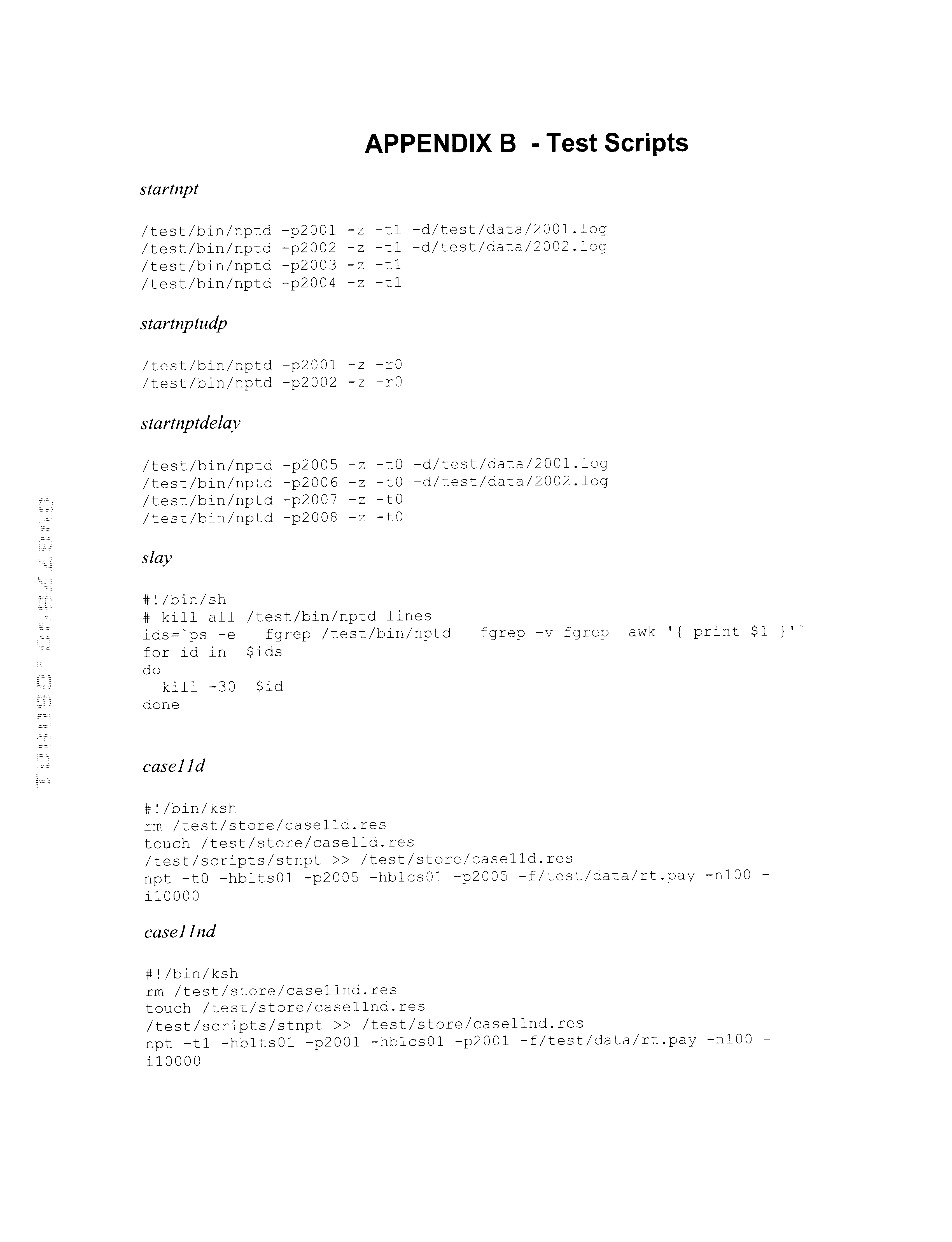
- An example command line illustrating a traversal from host 0 to host 1 to host 2 back to host 1 to host 0 in accordance with scripts found in Appendix B is as follows:
- the test methodology of the invention comprises at least the following functional test groups, including but not limited to: 1) Path Validation & Latency Measurements including tests for verifying that messages are going by the intended paths and for measuring round trip latencies. As an example, such test may be used to establish whether there are some hidden paths that could make the GIGAswitches disable links.
- Test for LAN latency are also included which will ultimately be affected by the number of stations on the FDDI rings; 2) Dual NIC Impact for testing the impact of dual FDDI NIC cards in an ATS system; 3) Failover/Failback to evaluate timings for LAN/WAN component failure modes and LAN/WAN component failback; and, 4) High Load Multiple Data Set Network Impact test for verifying real-time, provisioning and SS-RS data across the WAN.
- a critical benchmark test includes the Path Validation & Latency Measurements test.
- the following tests are configured to ensure that traffic uses the intended network paths: a) CS-CPFR-TS which verifies basic Communications Server (CS) to Transaction Server (TS) connectivity path through the Call Processing FDDI Ring (CPFR) such as illustrated in FIG. 5 ( a ).
- CS-CPFR-TS which verifies basic Communications Server (CS) to Transaction Server (TS) connectivity path through the Call Processing FDDI Ring (CPFR) such as illustrated in FIG. 5 ( a ).
- CPFR Call Processing FDDI Ring
- this test is for latency data
- b) a CS-CPFR-TS-CPFR-ATS test which verifies performance of the connectivity path from CS to TS over subnet 1 , and then from TS to the ATS via subnet 2 , such as illustrated in FIG.
- CS-CPFR-TS-CPFR-ATS-CPFR-GDS local test which verifies performance of the communications path from the CS to the local GDS, such as shown in FIG. 7 ( a ); d) a CS-CPFR-TS-CPFR-ATS-CPFR-Cisco 7513 FDDI-Cisco 7513 ATM-BPX-BPX-Cisco 7513 ATM-Cisco 7513 FDDI-CPFR-GDS (remote) test which verifies performance of the worst case real time connectivity path to a remote GDS such as shown in FIG.
- a TS-PFR-GIGAswitch-SS test which verifies performance of the connectivity path from the TS to the SS via the PFR and GIGAswitch such as shown in FIG. 9 ( a ), and which configuration may be considered identical to that using an ATS from a network point of view; f) a FEDS-GIGAswitch-Cisco 7513-BPX-BPX-Cisco 7513-GIGAswitch -BEDS test which verifies performance of the connectivity path from the FEDS across WAN path to the distant FEDS, such as illustrated in FIG.
- Preparation for each test includes the following procedures: For each server, e.g., DEC Alpha, used in the test, the following test directories are created: /test, /test/data, /test/store, /test/scripts and /test/bin. The NPT daemon and initiator executables are then placed on each server in the /test/bin directory, and the test scripts are placed on each server in the /test/scripts directory. For UNIX server devices, the default UNIX path is set to include /test/bin and /test/scripts. Each server is configured with the IP addresses for each site as shown in Appendix A with verification of all each network device configuration.
- each server e.g., DEC Alpha
- FIG. 5 ( a ) illustrates the logical test configuration for the CS-CPFR-TS connectivity path which verifies successful packet transfer from CS to TS over the FDDI, with no extraneous routes, via subnet 1 (IP — 1) addresses.
- IP — 1 subnet 1
- FIGS. 5 ( b ) and 5 ( c ) illustrate the packet delay results incurred for the example tests that measure round trip times from the CS to the TS, then back to the CS with a delay option (FIG. 5 ( b )) and no-delay option (FIG. 5 ( c )). As shown in. FIG.
- 5 ( b ) there is illustrated the packet delays incurred for messages sent by not utilizing the TCP_NODELAY socket option, i.e., with delay.
- CS-TS results of FIG. 5 ( b ) cyclic pattern in the roundtrip times suggests a buffer related mechanism may be at work.
- the roundtrip times recorded are in the sub-millisecond range which indicates normal expected LAN performance for this type of traffic.
- FIG. 6 ( a ) illustrates the logical test configuration for the CS-CPFR-TS-CPFR-ATS connectivity path which verifies successful packet transfer from the CS to ATS with no extraneous routes and, the successful transition of the packets from subnet 1 to subnet 2 .
- 100 messages are transmitted at 10 millisecond intervals from the CS to the TS (via the CPFR) which redirects the message packets to ATS which finally returns packets to the CS via the traversed route.
- NPT test Daemons on systems C, E and D see FIG.
- FIGS. 6 ( b ) and 6 ( c ) illustrate the results of the example tests for measuring the round trip times from the CS to the TS to the ATS, then back to the CS with a delay option (FIG. 6 ( b )) and no-delay option (FIG. 6 ( c )). Recorded roundtrip times in the 1-2 ms range for a three-system roundtrip is well within the desirable performance requirements and is clearly met as shown in the test results for the no delay option illustrated in FIG. 6 ( c ).
- FIG. 7 ( a ) illustrates the logical test configuration for the CS-CPFR-TS-CPFR-ATS-CPFR-GDS (local) connectivity path which verifies successful packet transfer from CS to GDS with no extraneous routes and, the successful transition of the packet from subnet 1 to subnet 2 .
- 100 messages are transmitted at 10 millisecond intervals from the CS directed to the TS which redirects test message packets to ATS which ATS redirects test message packets to GDS (local) which finally returns packets to the CS via traversed route.
- FIGS. 7 ( b ) and 7 ( c ) illustrate the packet delay results incurred for the example tests of measuring the round trip times from the CS-TS-ATS-GDS (local) with a delay option (FIG. 7 ( b )) and without the delay option (FIG. 7 ( c )).
- FIG. 8 ( a ) illustrates the logical test configuration for the CS-CPFR-TS-CPFR-ATS-CPFR-Cisco 7513 FDDI-Cisco 7513 ATM-BPX-BPX-Cisco 7513 ATM-Cisco 7513 FDDI-CPFR-GDS (remote) connectivity path for verifying successful packet transfer from a CS to remote GDS over the WAN, with no extraneous routes, using subnet 2 (real-time call processing traffic).
- CS-CPFR-TS-CPFR-ATS-CPFR-Cisco 7513 FDDI-Cisco 7513 ATM-BPX-BPX-Cisco 7513 ATM-Cisco 7513 FDDI-CPFR-GDS (remote) benchmark test methodology of the invention 100 messages are transmitted at 10 millisecond intervals from the CS directed to the TS which redirects message packets to ATS which redirects the message packets to the GDS (remote) which finally returns packets to the CS via the traversed route.
- NPT test Daemons on systems T, C, E and D see FIG.
- FIGS. 8 ( b ) and 8 ( c ) illustrate the packet delay results incurred for the example tests of measuring the round trip times from the CS-TS-ATS-GDS (remote) with a delay option (FIG. 8 ( b )) and without the delay option (FIG. 8 ( c )).
- FIG. 9 ( a ) illustrates the logical test configuration for the TS-PFR-GIGAswitch-SS connectivity path for verifying successful packet transfer from a TS to an SS with no extraneous routes via subnet 3 (Provisioning traffic).
- 1000 messages (300 octets) are transmitted at 500 microsecond intervals from the TS directed to the SS which SS redirects the message packets back to the TS.
- NPT test Daemons on systems C and A see FIG.
- FIG. 10 ( a ) illustrates the logical test configuration for the FEDS-GIGAswitch-Cisco 7513-BPX-BPX-Cisco 7513-GIGAswitch-Remote FEDS connectivity path for verifying successful packet transfer from a FEDS server to a BEDS server over the FDDI, with no extraneous routes, using subnet 3 (IP — 3) (provisioning traffic).
- IP — 3 subnet 3
- FEDS-GIGAswitch-Cisco 7513-BPX-BPX-Cisco 7513-GIGAswitch-Remote FEDS benchmark test methodology of the invention 100 messages are transmitted at 1 second intervals from the FEDS directed to the BEDS which returns the packets to the originating FEDS.
- this test methodology is initiated on system C in accordance with executable test scripts entitled case16d (delay) and case16nd (no delay), with example scripts being provided in Appendix B.
- 10 ( b ) and 10 ( c ) illustrate the packet delay results incurred when measuring the round trip times from the FEDS-Remote FEDS with a delay option (FIG. 10 ( b )) and without the delay option (FIG. 10 ( c )) according to these example test scripts.
- FIG. 11 ( a ) illustrates the logical test configuration for the SS-GIGAswitch-Cisco 7513-BPX-BPX-Cisco 7513-GIGAswitch-RS connectivity path for verifying successful packet transfer from the SS to the RS over the WAN using subnet 4 (IP — 4).
- IP — 4 subnet 4
- 10 messages of 7 Mbytes each, for example are transmitted at 10 second intervals from the SS to the RS which redirects the messages back to the SS.
- FIGS. 11 ( b ) and 11 ( c ) illustrate the packet delay results incurred when a test is run with a delay option (FIG. 11 ( b )) and without the delay option (FIG. 11 ( c )) according to these example test scripts.
- Further path validation and latency benchmark testing includes a test for verifying the impact of flooding the Call Processing LAN with real-time traffic (High load LAN latency, R/T traffic).
- R/T traffic Real-time traffic
- FIG. 5 ( a ) For this test, reference is further made to the CS-CPFR-TS test connectivity path illustrated in FIG. 5 ( a ).
- 10,000 (204 byte) messages at 1 microsecond intervals are transmitted to the target system with the round trip times for example messages traversing this path recorded.
- NPT test Daemons on systems E and D see FIG.
- FIGS. 12 ( a ) and 12 ( b ) illustrate the path latency (measured in ms) results when the example tests are run with a delay option (FIG. 12 ( a )) and without the delay option (FIG. 12 ( b )) according to these example test scripts.
- Successful performance criteria for this test includes receiving messages with latencies less than a predetermined timeout window.
- Another benchmark test includes a test for verifying the impact of flooding the Provisioning LAN with provisioning traffic (High load LAN latency, Provisioning traffic).
- provisioning traffic High load LAN latency, Provisioning traffic
- FIG. 9 ( a ) For this test, reference is made to the TS-PFR-GIGAswitch-SS test connectivity path illustrated in FIG. 9 ( a ).
- 10,000 2,040 byte messages at 1 microsecond intervals are transmitted to the target system with the round trip times for example messages traversing this path recorded.
- NPT test Daemons on systems C and A see FIG.
- FIGS. 13 ( a ) and 13 ( b ) illustrate the path latency (measured in ms) results for the LAN High Load provisioning traffic tests with a delay option (FIG. 13 ( a )) and without the delay option (FIG. 13 ( b )) according to these example test scripts. It is understood that as long as messages are received, the test is considered successful.
- Further benchmark testing includes a test for verifying the impact of flooding the WAN with real-time traffic (High load WAN latency, R/T traffic). For this test, reference is made only to the ATS to GDS portion of the CS-CPFR-TS-CPFR-ATS-CPFR-Cisco 7513 FDDI-Cisco 7513 ATM-BPX-BPX-Cisco 7513 ATM-Cisco 7513 FDDI-CPFR-GDS (remote) connectivity path illustrated in FIG. 8 ( a ).
- 10,000 (204 byte) messages at 1 microsecond intervals are transmitted to the target system with the round trip times for example messages traversing this path recorded.
- FIGS. 14 ( a ) and 14 ( b ) illustrate the path latency results for the PFR WAN Real-Time High Load provisioning traffic tests when run with a delay option (FIG. 14 ( a )) and without the delay option (FIG. 14 ( b )) according to these example test scripts.
- Successful performance criteria for this test includes receiving messages with latencies less than a predetermined timeout window.
- Another benchmark test includes a test for verifying the impact of flooding the Provisioning WAN with provisioning traffic (High load WAN latency, Provisioning traffic).
- provisioning traffic High load WAN latency, Provisioning traffic
- 10,000 2,040 byte messages are transmitted at 1 microsecond intervals to the target system with the round trip times for example messages traversing this path recorded.
- NPT test Daemons on systems F and A see FIG.
- FIGS. 15 ( a ) and 15 ( b ) illustrate the path latency results for the WAN Real-Time High Load provisioning traffic tests with a delay option (FIG. 15 ( a )) and without the delay option (FIG. 15 ( b )) according to these example test scripts.
- Successful performance criteria for this test includes receiving messages.
- Further benchmark testing includes a test for verifying the impact of flooding the WAN with SS-RS traffic.
- 200 seven (7 Mbyte) messages are transmitted at 1 microsecond intervals to the target system with the round trip times for example messages traversing this path recorded such as shown in FIG. 16 ( a ) and 16 ( b ).
- NPT test Daemons on systems A and F see FIG.
- FIGS. 16 ( a ) and 16 ( b ) illustrate the path latency results incurred for the WAN Statistics High Load traffic tests with a delay option (FIG. 16 ( a )) and without the delay option (FIG. 16 ( b )).
- a further benchmark test is provided for the purpose of demonstrating the performance of real-time packets between the ATS and (remote) GDS across the real-time PVC, while the provisioning and statistics PVC's are fully loaded. This represents a worst-case loading for the systems, routers and PVCs in the network of FIG. 2 .
- the configuration for this WAN real-time, provisioning and statistics ultra high load test is depicted as the ATS to remote GDS portion of FIG. 8 ( a ). For this test case, five servers were implemented, three servers of which functioning to send provisioning traffic (2040 byte messages), real time traffic (204 byte messages) and statistics traffic (7 Mb messages) simultaneously.
- a successful performance measure of this case is that no packets are lost, and real-time packet latency is unaffected.
- the provisioning and statistics BPX PVCs may be monitored at levels up to 70% utilized, with no data loss.
- a critical benchmark test includes the Dual NIC Impact test for testing the impact of dual FDDI NIC cards in an ATS system, i.e., measuring the effect on system resources of adding a second FDDI interface to an alpha system.
- the Dual NIC Impact test is configured to verify the following: a) that dual homing onto two double FDDI rings simultaneously works (i.e., may send/receive messages from both FDDI rings at the same time); b) verify the benchmark CPU overhead (dual vs single FDDI NIC); and, c) verify the benchmark I/O overhead (dual vs single FDDI NIC).
- FIG. 17 illustrates the logical test configuration 399 for the Dual NIC Impact test according to the preferred embodiment of the invention.
- a transaction server (TS) 402 e.g., DEC AlphaServer 388 is interfaced with multiple, e.g., four GeoLAN Hubs (two FDDI interfaces) 410 a , . . . , 410 d .
- the testing involves utilizing a script to enable the NPT tool to set up multiple transfers, first split between two physical interfaces, and then the same transfers through a single interface.
- a “Vmstat” utility is used to collect performance data during the NPT test run.
- the Dual NIC Impact test the following parameters are observed on the TS system 402 during the testing: a) throughput, in octets per second; b) total CPU utilization on the AlphaServer from all sources; c) CPU utilization by the system kernel of the AlphaServer; d) I/O rates for the FDDI cards in the AlphaServer; and, e) latency across the FDDI rings (end to end across the workstations' network stacks, including the NIC).
- the guideline for Dual NIC impact testing includes the following steps: Start vmstat on all servers, and direct output to a file; send a range of message rates to and from the AlphaServer 4100 simultaneously to and from two servers (Dual NIC Full-Duplex); and send a range of message rates to and from both servers to the AlphaServer 4100 (Dual NIC-Transmit and Receive).
- Traffic between server A and the AlphaServer 4100 may be 200 octets of application data (+IP overheads)—for simulating real-time traffic in the NIP configuration, and, traffic between server B and the AlphaServer 4100 may be a mixture of 200 octet messages and the maximum message size which IP supports for simulating non-real-time traffic (e.g. call plan downloads).
- Message rates may range from low load up to and beyond the maximum designed call processing capacity.
- the tests are run for approximately 10 minutes each with five iterations of each test being run, in order to provide a confidence level for the test results.
- server B is first connected to the GeoLAN FDDI hub P; a vmstat script stat541 provided in Appendix B, is initiated on system C for directing the output to a file.
- the NPT daemons are then started on systems B, C and D using script startnpt.
- the script case541txhigh is started on system C which script is provided in Appendix B.
- the npt is stopped on system C.
- server B is first connected to the GeoLAN FDDI hub P; a vmstat script stat542, provided in Appendix B, is initiated on system C for directing the output to a file.
- the NPT daemons are then started on systems B, C and D using script startnpt.
- a script case542rxhighp is started on system B and a script case542rxhighc is started on system D by coordinated console actions.
- the npt is stopped on systems B and D.
- server B is first connected to the GeoLAN FDDI hub P; a vmstat script stat543, provided in Appendix B, is initiated on system C for directing the output to a file.
- the NPT daemons are then started on systems B, C and D using script startnpt.
- a script case543fdhighp is started on system B and a script case543fdhighc is started on system D by coordinated console actions.
- the npt is stopped on systems B and D.
- the dual NIC procedure is repeated several times, e.g., three times, at each of three packet output rates: 2K output (4K total I/O), 4K output (8K total I/O), and 6K output (12K total I/O).
- a critical benchmark test includes the failover/failback tests for determining failover and failback times for each single component failure.
- the configuration for these sets of tests are similar to the benchmark topology for the LAN path and latency tests.
- the goal was to check if the traffic was using the expected routes.
- the failover and failback tests the aim is to measure failover times for each communications component.
- Successful failover/failback criteria are based on parameters including response times (before, during, and after failover), failover time to backup device, failback times from failback device to newly recovered primary device. Additionally, the effect on link status and routing may be monitored. Absolute success is determined by the observed data. For example, failover recovery times exceeding two (2) seconds is deemed excessive. Any detrimental effect on LAN/WAN routing capability, e.g., the inducement of unacceptable routes in failure recovery attempts, is additionally deemed unacceptable.
- the failover and failback tests are structured so that each single communications component is failed in turn with each failed component being brought back into service to measure failback times.
- the components targeted for failure include: the GeoLAN hub to GeoLAN hub; the Gigaswitch (use the data from the IP testing); the GIGAswitch to GeoLAN link; and, the 7513 router.
- a constant stream of real-time traffic is provided between two (2) of these components and the impact of failover and failback on response times is measured when a component is failed.
- a first set of tests is devised to measure failover to backup performance including: 1) a failure from the primary GeoLAN to the backup GeoLAN under message loading of 100 messages per second; 2) a failure from the primary GIGAswitch to the backup GIGAswitch under message loading of 100 messages per second; 3) a failure from the primary GIGAswitch to GeoLAN link to the backup GIGAswitch to GeoLAN link under message loading of 100 messages per second; and, 4) a failure from the primary Cisco 7513 router to the backup Cisco 7513 router under message loading of 100 messages per second.
- a second set of tests is devised to measure failback to primary performance including: 1) a failure from the primary GeoLAN to the backup GeoLAN under message loading of 100 messages per second, and, after recovery of the primary system, failback to the primary; 2) a failure from the primary GIGAswitch to the backup GIGAswitch under message loading of 100 messages per second and, after recovery of the primary system, failback to the primary; 3) a failure from the primary GIGAswitch to the GeoLAN link to the backup GIGAswitch to GeoLAN link under message loading of 100 messages per second, and then failback; and, 4) a failure from the primary Cisco 7513 router to the backup Cisco 7513 router under message loading of 100 messages per second, and, after recovery of the primary system, failback to the primary.
- a first test case is implemented for testing primary GeoLAN to the backup GeoLAN failover performance.
- a hub power failure is implemented as the primary GeoLAN to the backup GeoLAN failure, e.g., by removing power to the GeoLAN.
- the net effect of this failover is to fail the hub and the interfaces on the servers.
- the hardware setup comprises two Alphaservers and two GeoLAN hubs (reference is had to FIG. 3 ).
- the NPT tool is configured to send real-time messages of 204 octets once per millisecond, using the UDP protocol.
- the test is as follows: in a first step, hubs P and Q are disconnected from the GIGAswitch (FIG.
- servers B and C are dual home connected to hubs P and Q, ensuring the B port for servers B and C goes to hub P.
- nptd test script startnptdudp is then started (in UDP mode) on servers B and C such as provided in Appendix B.
- script case5111 is executed on server B for generating a stream of 100 messages/second, for example.
- hub P is powered down five (5) seconds after starting script case5111. After 10 seconds, the npt tool is stopped on server B.
- a “ps” (process status) command is performed that requests a list of all processes running on the systems.
- the net effect of the failover resulted in no messages being lost. However, several messages were delayed, e.g., starting with a 25 millisecond delay on the first message, with subsequent messages' delays shortening in a linear fashion to the normal latency period.
- an interface disconnect failure is implemented as the primary GeoLAN to the backup GeoLAN failure, e.g., by removing the “B” port connection to the receiving server on the primary hub and inducing failback after the initial failover recovery.
- the NPT tool is configured to send real-time messages of 204 octets once per millisecond, for example, using the UDP protocol.
- the test is as follows: in a first step, hubs P and Q are disconnected from the GIGAswitch (FIG. 3 ). Next, servers B and C are dual home connected to hubs P and Q, ensuring the B port for servers B and C goes to hub P.
- nptd test daemon is started (in UDP mode) on servers B and C implementing the script startnptdudp such as provided in Appendix B.
- script case5112 is executed on server B for generating a stream of 100 messages/second, for example.
- port “B” is disconnected on hub P connected to server B five (5) seconds after starting script case5112.
- the npt tool is stopped on server B.
- test is as follows: in a first step, servers A and B are dual home connected to switches J and K, ensuring the B port for each server A and B goes to switch J.
- the nptd test daemon is started (in UDP mode) on servers A and B using script startnptdudp such as provided in Appendix B.
- script case5121 is executed on server B for generating a stream of 100 messages/second, for example.
- switch J is powered down about five (5) seconds after starting the case5121 script.
- the npt tool is terminated on server B.
- the above-described “ps” process status
- greyp command
- kill commands are executed.
- servers A and B are dual home connected to switches J and K, ensuring the B port for each server A and B goes to hub P.
- the nptd test daemon is started (in UDP mode) on servers A and B implementing the script startnptdudp.
- script case5122 is executed on server B for generating a stream of 100 messages/second, for example.
- port “B” is disconnected from switch J connected to server B five (5) seconds after starting script case5122.
- the npt tool is stopped on server B.
- the above-described “ps” process status
- “grep” command, and kill commands are executed.
- test is as follows: in a first step, server B is dual home connected to switches J and K, ensuring the B port for server B goes to switch J. It is additionally ensured that the A and B ports on hubs P and Q are connected to M ports on GIGAswitches J and K. Next, the nptd test daemon is started (in UDP mode) on servers B and C using script startnptdudp.
- script case5131 is executed on server B for generating a stream of 100 messages/second, for example.
- switch J is powered down about five (5) seconds after starting the case5131 script.
- the npt tool is terminated on server B.
- test is as follows: in a first step, server B is dual home connected to switches J and K, ensuring the B port for server B goes to switch J. It is additionally ensured that the A and B ports on hubs P and Q are connected to M ports on GIGAswitches J and K. Next, the nptd test daemon is started (in UDP mode) on servers B and C using script startnptdudp. Then, script case5132 is executed on server B for generating a stream of 100 messages/second, for example.
- a router power failure is induced.
- the nptd test daemon is started (in UDP mode) on servers A and E using script startnptdudp.
- a script case5141 is executed on server A for generating a stream of 100 messages/second, for example.
- the primary router H is powered down five about (5) seconds after starting the script case5141, and, about 30 seconds thereafter, the npt tool is terminated on server A.
- the above-described “ps” process status
- “grep” command, and kill commands are executed.
- a UDP packet stream is sent from the b1ss01 server round trip to a distant system via the Cisco 7513 routers (FIG. 3 ).
- the routers were set up using HSRP as the failover mechanism.
- the primary router was then powered off.
- the characteristics of the failovers on the routers due to power loss include: calculation of event duration from the start of the buffer loss, e.g., at one millisecond per buffer, to the end of the buffer delay period, where the delay returns to the nominal delay value.
- nptd test daemon is started (in UDP mode) on servers A and E using script startnptdudp (See Appendix B).
- script case5142 is executed on server A for generating a stream of 100 messages/second, for example.
- both FDDI ports on the primary router H are disconnected about five about (5) seconds after starting script, and, after about 30 seconds, the npt tool is terminated on server A.
- the “ps” process status
- greyp command
- kill commands are executed.
- a first series of test cases is implemented for testing primary GeoLAN to the backup GeoLAN failure and failback.
- a hub power failure is induced, e.g., by removing power to the GeoLAN and, a recovery is implemented by again powering up the hub.
- FIG. 3 For the first test case, reference is had to FIG. 3 .
- hubs P and Q are disconnected from the GIGAswitch and, servers B and C are dual home connected to hubs P and Q, ensuring the B port for each server B and C goes to hub P.
- the nptd test daemon is started (in UDP mode) on servers B and C using script startnptdudp and script case5211 is executed on server B for generating a stream of 100 messages/second, for example.
- the hub P is powered down about five (5) seconds after starting the case5211 script.
- hub P is powered up and, after about 15 seconds thereafter, hub Q is powered down.
- the npt tool is terminated on server B.
- the “ps” process status
- “grep” command, and kill commands are executed.
- test is as follows: in a first step, hubs P and Q are disconnected from the GIGAswitch (FIG. 3 ). Next, servers B and C are dual home connected to hubs P and Q, ensuring the B port for servers B and C goes to hub P. Then, the nptd test daemon is started (in UDP mode) on servers B and C implementing the script startnptdudp. Then, script case5212 is executed on server B for generating a stream of 100 messages/second, for example.
- the port “B” connected to server B is disconnected from hub P about five (5) seconds after starting script case5212. After about 10 seconds thereafter, the port B is reconnected on hub P connected to server B and, after about 15 seconds thereafter, the port B is disconnected on hub Q connected to server B. Then, about 10 seconds after that, the npt tool is terminated on server B. Finally, the “ps” (process status), “grep” command, and kill commands are executed.
- a first failure caused approximately 240 messages to be lost during the failover; and, on recovery, the next 107 messages are delayed, with the first message delayed by approximately 250 ms with subsequent messages being delayed by shortening time periods.
- the amount of delay shortens in a linear fashion to the normal latency period.
- GIGAswitch to backup GIGAswitch failover and failback performance is tested.
- performance is measured when a switch power failure and recovery is induced. This case entails, dual home connecting servers A and B to switches J and K, ensuring that the B port for servers A and B goes to switch J.
- the nptd test daemon is started (in UDP mode) on servers A and B implementing the script startnptdudp and, script case5221 is started on server A for generating a stream of 100 messages/second, for example.
- switch J is powered down about five (5) seconds after starting script case5221. Then, after 10 seconds, the GIGAswitch J is powered up. After about 15 seconds, GIGAswitch K is powered down. Then, about 10 seconds after that, the npt tool is terminated on server A.
- the “ps” process status
- greyp command
- kill commands are executed.
- servers A and B are dual home connected to switches J and K (FIG. 3 ), ensuring the B port for servers A and B is connected to switch J.
- the nptd is started in UDP mode on servers A and B by using script startnptdudp and script case5222 is started on server A for generating a stream of 100 messages/second, for example.
- the B port on switch J connected to server A is disconnected about five (5) seconds after starting script. After about 10 seconds, the B port is reconnected on switch J connected to server A. Then, after 15 seconds, the B port is disconnected on switch K connected to server A, and after 10 seconds, the tool is stopped on server A.
- the “ps” process status
- “grep” command, and kill commands are executed.
- GIGAswitch to GeoLAN Link For the next series of cases, primary GIGAswitch to GeoLAN Link to backup GIGAswitch to GeoLAN Link failover and failback performance is tested.
- performance is measured when a switch power failure is induced.
- server B is dual home connected to switches J and K, ensuring the B port for server B goes is connected to switch J. It is additionally ensured that the A and B ports on hubs P and Q are connected to M ports on GIGAswitches J and K.
- the nptd is started in UDP mode on servers B and C by using script startnptdudp and script case5231 is started on server B for generating a stream of 100 messages/second, for example.
- switch J is powered down 5 seconds after starting script case5231. After about 15 seconds, switch J is powered up and about 15 seconds thereafter, switch K is powered down. Then, the npt tool is stopped on server B after about 10 seconds thereafter. Finally, the “ps” (process status), “grep” command, and kill commands are executed.
- server B is dual home connected to switches J and K, ensuring the B port for servers B and C goes to switch J. It is additionally ensured that the A and B ports on hubs P and Q are connected to M ports on GIGAswitches J and K. Then, the nptd is started in UDP mode on servers B and C by using script startnptdudp and script case5232 is started on server B for generating a stream of 100 messages/second, for example.
- the M port on switch J connected to GeoLAN P is disconnected about five (5) seconds after starting the script case5232. After about 15 seconds, the M port on switch J is reconnected and, about 15 seconds thereafter, the M port on switch K connected to GeoLAN P is disconnected. Then, the npt tool is stopped on server B after about 10 seconds thereafter. Finally, the “ps” (process status), “grep” command, and kill commands are executed.
- nptd is started in UDP mode on servers A and E (FIG. 3) by using script startnptdudp and script case5241 is started on server A for generating a stream of 100 messages/second, for example.
- the primary router H is powered down 5 seconds after starting script case5241.
- router H is powered up and about 30 seconds thereafter, router I is powered down.
- the npt tool is stopped on server A about 30 seconds thereafter.
- the “ps” process status
- greyp command
- kill commands are executed.
- nptd is started in UDP mode on servers A and E (FIG. 3) by using script startnptdudp and script case5242 is started on server A for generating a stream of 100 messages/second, for example.
- both FDDI ports on the primary router H are disconnected about five (5) seconds after starting script case5242.
- the FDDI ports to router H are reconnected.
- both FDDI ports on router I are disconnected.
- the npt tool on server A is terminated.
- the “ps” process status
- greyp command
- kill commands are executed.
- an UDP packet stream is sent from the b1ss01 server (FIG. 3) round trip to a distant system via the Cisco 7513 routers.
- the routers are set up using HSRP as the failover mechanism.
- the primary router then had the FDDI interface disconnected.
- the resulting characteristics of the failovers and failback on the routers due to interface loss include a measurement of the event duration from the start of deviation from the nominal latency to the recovery to the nominal latency by the total number of delayed buffers, e.g., when transmitted at one millisecond intervals.
- the novel benchmark testing methodology described herein fully proves out the performance benefits, resiliency and redundency designed into the NIP LAN/WAN of the invention. Functionally, the benchmark configuration and test described herein proves that the LAN/WAN design of the invention successfully segments the various traffic types, both within the LAN, and across the WAN. Further, it has been demonstrated that performance of the real-time traffic, including the cross WAN ATS-GDS traffic, is unaffected by provisioning and statistics traffic. Real time packet latencies (all latencies are measured as round-trip) across the WAN are proven to be approximately in the 1.6 ms range, regardless of other WAN traffic levels. This does not include WAN propagation delays which measure in the 10-14 ms range on the NIP production sites. Without traffic segregation afforded by the network topology of the invention, real-time packet latencies may increase above 7 seconds when the links are subject to heavy loads.
Abstract
Description
| TABLE 1 |
| Subnet Missions |
| IP | |
| No. | |
| 1 | Real-Time |
| 2 | ATS-GDS Real-Time |
| 3 | Provisioning Traffic (this will consist of three |
| separate entire class C addresses, and is not an | |
| actual subnet of the three previously defined | |
| class C addresses) | |
| 4 | SS- |
| 5 | WAN Primary Link PVCs (out of the XX.YYY.ZZ.0 |
| address space) | |
| 6 | WAN Secondary Link PVC (out of the XX.YYY.ZZ + 1.0 |
| address space) | |
| 7 | Allocated as a separate set of Class C addresses |
| for the |
|
| 8 | Allocated for IP Ethernet Management Rail |


Claims (27)
Priority Applications (3)
| Application Number | Priority Date | Filing Date | Title |
|---|---|---|---|
| US09/877,890 US6618389B2 (en) | 1999-11-22 | 2001-06-08 | Validation of call processing network performance |
| PCT/US2002/017771 WO2002101552A1 (en) | 2001-06-08 | 2002-06-06 | Validation of call processing network performance |
| US10/441,618 US6879562B2 (en) | 1999-11-22 | 2003-05-20 | Validation of call processing network performance |
Applications Claiming Priority (2)
| Application Number | Priority Date | Filing Date | Title |
|---|---|---|---|
| US09/444,099 US6385204B1 (en) | 1999-11-22 | 1999-11-22 | Network architecture and call processing system |
| US09/877,890 US6618389B2 (en) | 1999-11-22 | 2001-06-08 | Validation of call processing network performance |
Related Parent Applications (1)
| Application Number | Title | Priority Date | Filing Date |
|---|---|---|---|
| US09/444,099 Continuation-In-Part US6385204B1 (en) | 1999-11-22 | 1999-11-22 | Network architecture and call processing system |
Related Child Applications (1)
| Application Number | Title | Priority Date | Filing Date |
|---|---|---|---|
| US10/441,618 Continuation US6879562B2 (en) | 1999-11-22 | 2003-05-20 | Validation of call processing network performance |
Publications (2)
| Publication Number | Publication Date |
|---|---|
| US20020172158A1 US20020172158A1 (en) | 2002-11-21 |
| US6618389B2 true US6618389B2 (en) | 2003-09-09 |
Family
ID=25370926
Family Applications (2)
| Application Number | Title | Priority Date | Filing Date |
|---|---|---|---|
| US09/877,890 Expired - Fee Related US6618389B2 (en) | 1999-11-22 | 2001-06-08 | Validation of call processing network performance |
| US10/441,618 Expired - Fee Related US6879562B2 (en) | 1999-11-22 | 2003-05-20 | Validation of call processing network performance |
Family Applications After (1)
| Application Number | Title | Priority Date | Filing Date |
|---|---|---|---|
| US10/441,618 Expired - Fee Related US6879562B2 (en) | 1999-11-22 | 2003-05-20 | Validation of call processing network performance |
Country Status (2)
| Country | Link |
|---|---|
| US (2) | US6618389B2 (en) |
| WO (1) | WO2002101552A1 (en) |
Cited By (19)
| Publication number | Priority date | Publication date | Assignee | Title |
|---|---|---|---|---|
| US20020093917A1 (en) * | 2001-01-16 | 2002-07-18 | Networks Associates,Inc. D/B/A Network Associates, Inc. | Method and apparatus for passively calculating latency for a network appliance |
| US20020133575A1 (en) * | 2001-02-22 | 2002-09-19 | Viola Networks Ltd. | Troubleshooting remote internet users |
| US20020167952A1 (en) * | 2001-05-09 | 2002-11-14 | Chiaro Networks, Ltd. | System and method for TCP connection protection switching |
| US20030115036A1 (en) * | 2001-12-19 | 2003-06-19 | Institute For Information Industry | Software-based method for simulation of multiple access networks |
| US20040040010A1 (en) * | 2002-04-22 | 2004-02-26 | Kirill Kounik | Slowing network connection for application optimization |
| US6879562B2 (en) * | 1999-11-22 | 2005-04-12 | Mci Inc. | Validation of call processing network performance |
| US6941551B1 (en) * | 2000-04-11 | 2005-09-06 | Microsoft Corporation | Method and system for creating a quality of service message |
| US20050195835A1 (en) * | 2004-03-02 | 2005-09-08 | Savage Donnie V. | Router configured for outputting update messages specifying a detected attribute change of a connected active path according to a prescribed routing protocol |
| US6958977B1 (en) | 2000-06-06 | 2005-10-25 | Viola Networks Ltd | Network packet tracking |
| US6990616B1 (en) * | 2000-04-24 | 2006-01-24 | Attune Networks Ltd. | Analysis of network performance |
| US20060221843A1 (en) * | 2005-04-01 | 2006-10-05 | Viola Networks Ltd. | Duplex mismatch testing |
| US20070076605A1 (en) * | 2005-09-13 | 2007-04-05 | Israel Cidon | Quality of service testing of communications networks |
| US20070195707A1 (en) * | 2006-02-22 | 2007-08-23 | Viola Networks Ltd. | Sampling test of network performance |
| US20080022000A1 (en) * | 2004-11-11 | 2008-01-24 | Shinji Furuya | Ip-Packet Relay Method and Gateway in Communication Network |
| US7529836B1 (en) * | 2004-01-08 | 2009-05-05 | Network Appliance, Inc. | Technique for throttling data access requests |
| US20130275518A1 (en) * | 2012-04-12 | 2013-10-17 | Ariel Tseitlin | Method and system for evaluating the resiliency of a distributed computing service by inducing a latency |
| US11490432B1 (en) | 2021-05-28 | 2022-11-01 | T-Mobile Usa, Inc. | Unified query tool for network function virtualization architecture |
| US11509704B1 (en) | 2021-05-28 | 2022-11-22 | T-Mobile Usa. Inc. | Product validation based on simulated enhanced calling or messaging communications services in telecommunications network |
| US11546243B1 (en) | 2021-05-28 | 2023-01-03 | T-Mobile Usa, Inc. | Unified interface and tracing tool for network function virtualization architecture |
Families Citing this family (18)
| Publication number | Priority date | Publication date | Assignee | Title |
|---|---|---|---|---|
| JP3828321B2 (en) * | 1999-08-31 | 2006-10-04 | 富士通株式会社 | Computer-readable recording medium on which load test apparatus and load test program are recorded |
| US7117447B2 (en) * | 2001-06-08 | 2006-10-03 | Mci, Llc | Graphical user interface (GUI) based call application system |
| US7613160B2 (en) * | 2002-12-24 | 2009-11-03 | Intel Corporation | Method and apparatus to establish communication with wireless communication networks |
| NO318887B1 (en) * | 2003-09-05 | 2005-05-18 | Paradial As | Sanntidsproxyer |
| US7447222B2 (en) * | 2003-11-12 | 2008-11-04 | Hewlett-Packard Development Company, L.P. | Automated path tracing through switching mesh |
| US7565436B2 (en) * | 2003-12-24 | 2009-07-21 | Nortel Networks Limited | Ethernet to frame relay interworking with multiple quality of service levels |
| US8213439B2 (en) * | 2004-01-30 | 2012-07-03 | Hewlett-Packard Development Company, L.P. | Method and system for managing a network having an HSRP group |
| JP4264035B2 (en) * | 2004-06-25 | 2009-05-13 | 株式会社東芝 | Information processing apparatus, information processing program, and information processing method |
| CN1937541B (en) * | 2005-09-20 | 2010-08-11 | 华为技术有限公司 | Network performance test method |
| US7151884B1 (en) * | 2005-10-20 | 2006-12-19 | Cisco Technology, Inc. | Method and system for re-establishing communication link in a network by using viral communication |
| KR101409991B1 (en) * | 2007-04-16 | 2014-06-20 | 삼성전자주식회사 | Method and apparatus for data transfer in peer-to-peer network |
| US9996858B1 (en) | 2012-11-05 | 2018-06-12 | Quantcast Corporation | Adaptive bidding for networked advertising |
| US10257019B2 (en) * | 2015-12-04 | 2019-04-09 | Arista Networks, Inc. | Link aggregation split-brain detection and recovery |
| RO132177A2 (en) * | 2016-03-21 | 2017-09-29 | Ixia, A California Corporation | Methods, system and computerized medium for testing network equipment devices using connectionless protocol |
| US10193773B2 (en) | 2016-11-09 | 2019-01-29 | Keysight Technologies Singapore (Holdings) Pte. Ltd. | Methods, systems, and computer readable media for distributed network packet statistics collection in a test environment |
| JP6812787B2 (en) * | 2016-12-27 | 2021-01-13 | 富士通株式会社 | Information processing device, failover time measurement method and failover time measurement program |
| US10764148B2 (en) | 2017-11-29 | 2020-09-01 | Keysight Technologies, Inc. | Methods, systems, and computer readable media for network traffic statistics collection |
| CN113993158B (en) * | 2021-10-28 | 2023-05-23 | 成都长虹网络科技有限责任公司 | Network quality monitoring method, system, computer equipment and storage medium |
Citations (11)
| Publication number | Priority date | Publication date | Assignee | Title |
|---|---|---|---|---|
| US5790634A (en) | 1995-07-25 | 1998-08-04 | Bell Atlantic Network Services, Inc. | Combination system for proactively and reactively maintaining telephone network facilities in a public switched telephone system |
| US5838683A (en) | 1995-03-13 | 1998-11-17 | Selsius Systems Inc. | Distributed interactive multimedia system architecture |
| US5982780A (en) | 1995-12-28 | 1999-11-09 | Dynarc Ab | Resource management scheme and arrangement |
| US6012152A (en) | 1996-11-27 | 2000-01-04 | Telefonaktiebolaget Lm Ericsson (Publ) | Software fault management system |
| US6091732A (en) | 1997-11-20 | 2000-07-18 | Cisco Systems, Inc. | Method for configuring distributed internet protocol gateways with lan emulation |
| US6091708A (en) * | 1996-06-28 | 2000-07-18 | Oki Electric Industry Co., Ltd. | Traffic shaper with multiply queued virtual paths |
| US6122363A (en) * | 1998-07-24 | 2000-09-19 | Mci Communications Corp. | Multi-protocol interface apparatus at a service control point |
| US6137874A (en) * | 1997-06-03 | 2000-10-24 | At&T Corp. | Method of using carrier information for enhanced call data processing by a telecommunications provider |
| US6172981B1 (en) | 1997-10-30 | 2001-01-09 | International Business Machines Corporation | Method and system for distributing network routing functions to local area network stations |
| US6182125B1 (en) | 1998-10-13 | 2001-01-30 | 3Com Corporation | Methods for determining sendable information content based on a determined network latency |
| US6295292B1 (en) * | 1997-03-06 | 2001-09-25 | Bell Atlantic Network Services, Inc. | Inbound gateway authorization processing for inter-carrier internet telephony |
Family Cites Families (3)
| Publication number | Priority date | Publication date | Assignee | Title |
|---|---|---|---|---|
| JPH06508008A (en) * | 1991-06-12 | 1994-09-08 | ヒューレット・パッカード・カンパニー | Method and apparatus for testing packet-based networks |
| IL121898A0 (en) * | 1997-10-07 | 1998-03-10 | Cidon Israel | A method and apparatus for active testing and fault allocation of communication networks |
| US6618389B2 (en) * | 1999-11-22 | 2003-09-09 | Worldcom, Inc. | Validation of call processing network performance |
-
2001
- 2001-06-08 US US09/877,890 patent/US6618389B2/en not_active Expired - Fee Related
-
2002
- 2002-06-06 WO PCT/US2002/017771 patent/WO2002101552A1/en not_active Application Discontinuation
-
2003
- 2003-05-20 US US10/441,618 patent/US6879562B2/en not_active Expired - Fee Related
Patent Citations (11)
| Publication number | Priority date | Publication date | Assignee | Title |
|---|---|---|---|---|
| US5838683A (en) | 1995-03-13 | 1998-11-17 | Selsius Systems Inc. | Distributed interactive multimedia system architecture |
| US5790634A (en) | 1995-07-25 | 1998-08-04 | Bell Atlantic Network Services, Inc. | Combination system for proactively and reactively maintaining telephone network facilities in a public switched telephone system |
| US5982780A (en) | 1995-12-28 | 1999-11-09 | Dynarc Ab | Resource management scheme and arrangement |
| US6091708A (en) * | 1996-06-28 | 2000-07-18 | Oki Electric Industry Co., Ltd. | Traffic shaper with multiply queued virtual paths |
| US6012152A (en) | 1996-11-27 | 2000-01-04 | Telefonaktiebolaget Lm Ericsson (Publ) | Software fault management system |
| US6295292B1 (en) * | 1997-03-06 | 2001-09-25 | Bell Atlantic Network Services, Inc. | Inbound gateway authorization processing for inter-carrier internet telephony |
| US6137874A (en) * | 1997-06-03 | 2000-10-24 | At&T Corp. | Method of using carrier information for enhanced call data processing by a telecommunications provider |
| US6172981B1 (en) | 1997-10-30 | 2001-01-09 | International Business Machines Corporation | Method and system for distributing network routing functions to local area network stations |
| US6091732A (en) | 1997-11-20 | 2000-07-18 | Cisco Systems, Inc. | Method for configuring distributed internet protocol gateways with lan emulation |
| US6122363A (en) * | 1998-07-24 | 2000-09-19 | Mci Communications Corp. | Multi-protocol interface apparatus at a service control point |
| US6182125B1 (en) | 1998-10-13 | 2001-01-30 | 3Com Corporation | Methods for determining sendable information content based on a determined network latency |
Cited By (33)
| Publication number | Priority date | Publication date | Assignee | Title |
|---|---|---|---|---|
| US6879562B2 (en) * | 1999-11-22 | 2005-04-12 | Mci Inc. | Validation of call processing network performance |
| US20060036749A1 (en) * | 2000-04-11 | 2006-02-16 | Microsoft Corporation | Method and system for creating a quality of service message |
| US6941551B1 (en) * | 2000-04-11 | 2005-09-06 | Microsoft Corporation | Method and system for creating a quality of service message |
| US7554925B2 (en) | 2000-04-11 | 2009-06-30 | Microsoft Corporation | Method and system for creating a quality of service message |
| US6990616B1 (en) * | 2000-04-24 | 2006-01-24 | Attune Networks Ltd. | Analysis of network performance |
| US6958977B1 (en) | 2000-06-06 | 2005-10-25 | Viola Networks Ltd | Network packet tracking |
| US20020093917A1 (en) * | 2001-01-16 | 2002-07-18 | Networks Associates,Inc. D/B/A Network Associates, Inc. | Method and apparatus for passively calculating latency for a network appliance |
| US6868069B2 (en) * | 2001-01-16 | 2005-03-15 | Networks Associates Technology, Inc. | Method and apparatus for passively calculating latency for a network appliance |
| US20020133575A1 (en) * | 2001-02-22 | 2002-09-19 | Viola Networks Ltd. | Troubleshooting remote internet users |
| US6853617B2 (en) * | 2001-05-09 | 2005-02-08 | Chiaro Networks, Ltd. | System and method for TCP connection protection switching |
| US20020167952A1 (en) * | 2001-05-09 | 2002-11-14 | Chiaro Networks, Ltd. | System and method for TCP connection protection switching |
| US20030115036A1 (en) * | 2001-12-19 | 2003-06-19 | Institute For Information Industry | Software-based method for simulation of multiple access networks |
| US7346896B2 (en) * | 2002-04-22 | 2008-03-18 | Sun Microsystems, Inc. | Slowing network connection for application optimization |
| US20040040010A1 (en) * | 2002-04-22 | 2004-02-26 | Kirill Kounik | Slowing network connection for application optimization |
| US7529836B1 (en) * | 2004-01-08 | 2009-05-05 | Network Appliance, Inc. | Technique for throttling data access requests |
| US20050195835A1 (en) * | 2004-03-02 | 2005-09-08 | Savage Donnie V. | Router configured for outputting update messages specifying a detected attribute change of a connected active path according to a prescribed routing protocol |
| US7720054B2 (en) | 2004-03-02 | 2010-05-18 | Cisco Technology, Inc. | Router configured for outputting update messages specifying a detected attribute change of a connected active path according to a prescribed routing protocol |
| US20080022000A1 (en) * | 2004-11-11 | 2008-01-24 | Shinji Furuya | Ip-Packet Relay Method and Gateway in Communication Network |
| US7525922B2 (en) | 2005-04-01 | 2009-04-28 | Cisco Technology, Inc. | Duplex mismatch testing |
| US20060221843A1 (en) * | 2005-04-01 | 2006-10-05 | Viola Networks Ltd. | Duplex mismatch testing |
| US20070076605A1 (en) * | 2005-09-13 | 2007-04-05 | Israel Cidon | Quality of service testing of communications networks |
| US7835293B2 (en) | 2005-09-13 | 2010-11-16 | Cisco Technology, Inc. | Quality of service testing of communications networks |
| US20070195707A1 (en) * | 2006-02-22 | 2007-08-23 | Viola Networks Ltd. | Sampling test of network performance |
| US7990887B2 (en) | 2006-02-22 | 2011-08-02 | Cisco Technology, Inc. | Sampling test of network performance |
| US20130275518A1 (en) * | 2012-04-12 | 2013-10-17 | Ariel Tseitlin | Method and system for evaluating the resiliency of a distributed computing service by inducing a latency |
| US9015289B2 (en) * | 2012-04-12 | 2015-04-21 | Netflix, Inc. | Method and system for evaluating the resiliency of a distributed computing service by inducing a latency |
| US9864666B2 (en) | 2012-04-12 | 2018-01-09 | Netflix, Inc. | Method and system for evaluating the resiliency of a distributed computing service by inducing latency |
| US11490432B1 (en) | 2021-05-28 | 2022-11-01 | T-Mobile Usa, Inc. | Unified query tool for network function virtualization architecture |
| US11509704B1 (en) | 2021-05-28 | 2022-11-22 | T-Mobile Usa. Inc. | Product validation based on simulated enhanced calling or messaging communications services in telecommunications network |
| US11546243B1 (en) | 2021-05-28 | 2023-01-03 | T-Mobile Usa, Inc. | Unified interface and tracing tool for network function virtualization architecture |
| US11770323B2 (en) | 2021-05-28 | 2023-09-26 | T-Mobile Usa, Inc. | Unified interface and tracing tool for network function virtualization architecture |
| US11811844B2 (en) | 2021-05-28 | 2023-11-07 | T-Mobile Usa, Inc. | Product validation based on simulated enhanced calling or messaging communications services in telecommunications network |
| US11849492B2 (en) | 2021-05-28 | 2023-12-19 | T-Mobile Usa, Inc. | Unified query tool for network function virtualization architecture |
Also Published As
| Publication number | Publication date |
|---|---|
| US6879562B2 (en) | 2005-04-12 |
| WO2002101552A1 (en) | 2002-12-19 |
| US20020172158A1 (en) | 2002-11-21 |
| US20030198186A1 (en) | 2003-10-23 |
Similar Documents
| Publication | Publication Date | Title |
|---|---|---|
| US6618389B2 (en) | Validation of call processing network performance | |
| Markopoulou et al. | Characterization of failures in an operational IP backbone network | |
| US7804771B2 (en) | Method and apparatus for protection switching in virtual private networks | |
| US6483811B1 (en) | System and method for emulating a distributed network | |
| Cisco | 9.3.35 Version Software Release Notes Cisco WAN Switching | |
| Cisco | 9.3.31 Version Software Release Notes Cisco WAN Switching | |
| Cisco | 9.3.30 Version Software Release Notes Cisco WAN Switching | |
| Cisco | Alphabetical Listing of SES PNNI Controller Commands | |
| Cisco | 9.2.41 Version Software Release Notes Cisco WAN Switching System Software | |
| Cisco | 9.1.25 Version Software Release Notes Cisco WAN Switching System Software | |
| Cisco | Release Notes for the Catalyst 8510 and the LightStream 1010 Switch for Cisco IOS Release 12.1(12c)EY | |
| Cisco | Alphabetical List of MGX 8850 Commands | |
| Cisco | 9.1.30 Version Software Release Notes Cisco WAN Switching System Software | |
| Cisco | 9.3.36 Version Software Release Notes Cisco WAN Switching System Software | |
| Cisco | 9.1.24 Version Software Release Notes Cisco WAN Switching System Software | |
| Cisco | Release Notes for the Catalyst 8510 and the LightStream 1010 Switch for Cisco IOS Release 12.1(11b)E4 | |
| Cisco | Release Notes for the Catalyst 8510 and the LightStream 1010 Switch for Cisco IOS Release 12.1(11b)E5 | |
| Cisco | Cisco IOS Release 12.0(23) Release Notes for LightStream 1010 ATM Switch Software | |
| Cisco | Cisco IOS Release 12.0(20) Release Notes for LightStream 1010 ATM Switch Software | |
| Cisco | Release Notes for the Catalyst 8510 and LightStream 1010 ATM Switch for Cisco IOS Release 12.0(20)W5(24a) | |
| Cisco | Cisco IOS Release 12.0(22) Release Notes for LightStream 1010 ATM Swich Software | |
| Cisco | Release Notes | |
| Cisco | Release Notes | |
| Cisco | Release Notes for the Catalyst 8510 and LS1010 ATM Switch for Cisco IOS Release 12.0(22)W5(25) | |
| Cisco | Release Notes for the Catalyst 8510 and the LightStream 1010 Switch for Cisco IOS Release 12.1(12c)E |
Legal Events
| Date | Code | Title | Description |
|---|---|---|---|
| AS | Assignment |
Owner name: WORLDCOM, INC., MISSISSIPPI Free format text: ASSIGNMENT OF ASSIGNORS INTEREST;ASSIGNORS:HOEFELMEYER, RALPH S.;HUTCHINSON, MICHAEL L.;REEL/FRAME:012236/0762;SIGNING DATES FROM 20010919 TO 20010920 |
|
| AS | Assignment |
Owner name: MCI, INC., VIRGINIA Free format text: CHANGE OF NAME;ASSIGNOR:WORLDCOM, INC.;REEL/FRAME:014754/0134 Effective date: 20040419 |
|
| FPAY | Fee payment |
Year of fee payment: 4 |
|
| FPAY | Fee payment |
Year of fee payment: 8 |
|
| AS | Assignment |
Owner name: MCI, LLC, VIRGINIA Free format text: MERGER;ASSIGNOR:MCI, INC.;REEL/FRAME:032632/0244 Effective date: 20060106 Owner name: VERIZON BUSINESS GLOBAL LLC, VIRGINIA Free format text: CHANGE OF NAME;ASSIGNOR:MCI, LLC;REEL/FRAME:032632/0404 Effective date: 20061120 |
|
| AS | Assignment |
Owner name: VERIZON PATENT AND LICENSING INC., NEW JERSEY Free format text: ASSIGNMENT OF ASSIGNORS INTEREST;ASSIGNOR:VERIZON BUSINESS GLOBAL LLC;REEL/FRAME:032734/0502 Effective date: 20140409 |
|
| REMI | Maintenance fee reminder mailed | ||
| LAPS | Lapse for failure to pay maintenance fees | ||
| STCH | Information on status: patent discontinuation |
Free format text: PATENT EXPIRED DUE TO NONPAYMENT OF MAINTENANCE FEES UNDER 37 CFR 1.362 |
|
| FP | Lapsed due to failure to pay maintenance fee |
Effective date: 20150909 |
|
| AS | Assignment |
Owner name: VERIZON PATENT AND LICENSING INC., NEW JERSEY Free format text: CORRECTIVE ASSIGNMENT TO CORRECT THE ASSIGNEE PREVIOUSLY RECORDED AT REEL: 032734 FRAME: 0502. ASSIGNOR(S) HEREBY CONFIRMS THE ASSIGNMENT;ASSIGNOR:VERIZON BUSINESS GLOBAL LLC;REEL/FRAME:044626/0088 Effective date: 20140409 |