US6618003B2 - Method of detecting interference conditions of a radar device and a radar device - Google Patents
Method of detecting interference conditions of a radar device and a radar device Download PDFInfo
- Publication number
- US6618003B2 US6618003B2 US10/080,651 US8065102A US6618003B2 US 6618003 B2 US6618003 B2 US 6618003B2 US 8065102 A US8065102 A US 8065102A US 6618003 B2 US6618003 B2 US 6618003B2
- Authority
- US
- United States
- Prior art keywords
- radar device
- signals
- interference
- frequency
- target signals
- Prior art date
- Legal status (The legal status is an assumption and is not a legal conclusion. Google has not performed a legal analysis and makes no representation as to the accuracy of the status listed.)
- Expired - Fee Related
Links
Images
Classifications
-
- G—PHYSICS
- G01—MEASURING; TESTING
- G01S—RADIO DIRECTION-FINDING; RADIO NAVIGATION; DETERMINING DISTANCE OR VELOCITY BY USE OF RADIO WAVES; LOCATING OR PRESENCE-DETECTING BY USE OF THE REFLECTION OR RERADIATION OF RADIO WAVES; ANALOGOUS ARRANGEMENTS USING OTHER WAVES
- G01S13/00—Systems using the reflection or reradiation of radio waves, e.g. radar systems; Analogous systems using reflection or reradiation of waves whose nature or wavelength is irrelevant or unspecified
- G01S13/88—Radar or analogous systems specially adapted for specific applications
- G01S13/93—Radar or analogous systems specially adapted for specific applications for anti-collision purposes
- G01S13/931—Radar or analogous systems specially adapted for specific applications for anti-collision purposes of land vehicles
-
- G—PHYSICS
- G01—MEASURING; TESTING
- G01S—RADIO DIRECTION-FINDING; RADIO NAVIGATION; DETERMINING DISTANCE OR VELOCITY BY USE OF RADIO WAVES; LOCATING OR PRESENCE-DETECTING BY USE OF THE REFLECTION OR RERADIATION OF RADIO WAVES; ANALOGOUS ARRANGEMENTS USING OTHER WAVES
- G01S7/00—Details of systems according to groups G01S13/00, G01S15/00, G01S17/00
- G01S7/02—Details of systems according to groups G01S13/00, G01S15/00, G01S17/00 of systems according to group G01S13/00
- G01S7/023—Interference mitigation, e.g. reducing or avoiding non-intentional interference with other HF-transmitters, base station transmitters for mobile communication or other radar systems, e.g. using electro-magnetic interference [EMI] reduction techniques
-
- G—PHYSICS
- G01—MEASURING; TESTING
- G01S—RADIO DIRECTION-FINDING; RADIO NAVIGATION; DETERMINING DISTANCE OR VELOCITY BY USE OF RADIO WAVES; LOCATING OR PRESENCE-DETECTING BY USE OF THE REFLECTION OR RERADIATION OF RADIO WAVES; ANALOGOUS ARRANGEMENTS USING OTHER WAVES
- G01S7/00—Details of systems according to groups G01S13/00, G01S15/00, G01S17/00
- G01S7/02—Details of systems according to groups G01S13/00, G01S15/00, G01S17/00 of systems according to group G01S13/00
- G01S7/40—Means for monitoring or calibrating
- G01S7/4004—Means for monitoring or calibrating of parts of a radar system
- G01S7/4039—Means for monitoring or calibrating of parts of a radar system of sensor or antenna obstruction, e.g. dirt- or ice-coating
-
- G—PHYSICS
- G01—MEASURING; TESTING
- G01S—RADIO DIRECTION-FINDING; RADIO NAVIGATION; DETERMINING DISTANCE OR VELOCITY BY USE OF RADIO WAVES; LOCATING OR PRESENCE-DETECTING BY USE OF THE REFLECTION OR RERADIATION OF RADIO WAVES; ANALOGOUS ARRANGEMENTS USING OTHER WAVES
- G01S13/00—Systems using the reflection or reradiation of radio waves, e.g. radar systems; Analogous systems using reflection or reradiation of waves whose nature or wavelength is irrelevant or unspecified
- G01S13/88—Radar or analogous systems specially adapted for specific applications
- G01S13/93—Radar or analogous systems specially adapted for specific applications for anti-collision purposes
- G01S13/931—Radar or analogous systems specially adapted for specific applications for anti-collision purposes of land vehicles
- G01S2013/9314—Parking operations
-
- G—PHYSICS
- G01—MEASURING; TESTING
- G01S—RADIO DIRECTION-FINDING; RADIO NAVIGATION; DETERMINING DISTANCE OR VELOCITY BY USE OF RADIO WAVES; LOCATING OR PRESENCE-DETECTING BY USE OF THE REFLECTION OR RERADIATION OF RADIO WAVES; ANALOGOUS ARRANGEMENTS USING OTHER WAVES
- G01S13/00—Systems using the reflection or reradiation of radio waves, e.g. radar systems; Analogous systems using reflection or reradiation of waves whose nature or wavelength is irrelevant or unspecified
- G01S13/88—Radar or analogous systems specially adapted for specific applications
- G01S13/93—Radar or analogous systems specially adapted for specific applications for anti-collision purposes
- G01S13/931—Radar or analogous systems specially adapted for specific applications for anti-collision purposes of land vehicles
- G01S2013/9315—Monitoring blind spots
-
- G—PHYSICS
- G01—MEASURING; TESTING
- G01S—RADIO DIRECTION-FINDING; RADIO NAVIGATION; DETERMINING DISTANCE OR VELOCITY BY USE OF RADIO WAVES; LOCATING OR PRESENCE-DETECTING BY USE OF THE REFLECTION OR RERADIATION OF RADIO WAVES; ANALOGOUS ARRANGEMENTS USING OTHER WAVES
- G01S13/00—Systems using the reflection or reradiation of radio waves, e.g. radar systems; Analogous systems using reflection or reradiation of waves whose nature or wavelength is irrelevant or unspecified
- G01S13/88—Radar or analogous systems specially adapted for specific applications
- G01S13/93—Radar or analogous systems specially adapted for specific applications for anti-collision purposes
- G01S13/931—Radar or analogous systems specially adapted for specific applications for anti-collision purposes of land vehicles
- G01S2013/9327—Sensor installation details
- G01S2013/93271—Sensor installation details in the front of the vehicles
-
- G—PHYSICS
- G01—MEASURING; TESTING
- G01S—RADIO DIRECTION-FINDING; RADIO NAVIGATION; DETERMINING DISTANCE OR VELOCITY BY USE OF RADIO WAVES; LOCATING OR PRESENCE-DETECTING BY USE OF THE REFLECTION OR RERADIATION OF RADIO WAVES; ANALOGOUS ARRANGEMENTS USING OTHER WAVES
- G01S13/00—Systems using the reflection or reradiation of radio waves, e.g. radar systems; Analogous systems using reflection or reradiation of waves whose nature or wavelength is irrelevant or unspecified
- G01S13/88—Radar or analogous systems specially adapted for specific applications
- G01S13/93—Radar or analogous systems specially adapted for specific applications for anti-collision purposes
- G01S13/931—Radar or analogous systems specially adapted for specific applications for anti-collision purposes of land vehicles
- G01S2013/9327—Sensor installation details
- G01S2013/93272—Sensor installation details in the back of the vehicles
-
- G—PHYSICS
- G01—MEASURING; TESTING
- G01S—RADIO DIRECTION-FINDING; RADIO NAVIGATION; DETERMINING DISTANCE OR VELOCITY BY USE OF RADIO WAVES; LOCATING OR PRESENCE-DETECTING BY USE OF THE REFLECTION OR RERADIATION OF RADIO WAVES; ANALOGOUS ARRANGEMENTS USING OTHER WAVES
- G01S13/00—Systems using the reflection or reradiation of radio waves, e.g. radar systems; Analogous systems using reflection or reradiation of waves whose nature or wavelength is irrelevant or unspecified
- G01S13/88—Radar or analogous systems specially adapted for specific applications
- G01S13/93—Radar or analogous systems specially adapted for specific applications for anti-collision purposes
- G01S13/931—Radar or analogous systems specially adapted for specific applications for anti-collision purposes of land vehicles
- G01S2013/9327—Sensor installation details
- G01S2013/93274—Sensor installation details on the side of the vehicles
Definitions
- the present invention relates to a method of detecting interference conditions of a radar device.
- the present invention also relates to a radar device.
- radar devices there are numerous applications for radar devices in various fields of the industry. For example, the use of radar sensors is possible for short-range sensors in motor vehicles.
- a sending antenna in such radar devices emits electromagnetic waves. When these electromagnetic waves strike an obstacle, they are reflected and received by another antenna or the same antenna after being reflected. The received signals are then sent to a signal processing and analyzing unit.
- radar sensors are used for measuring the distance from targets and/or the relative velocity with respect to such a target outside the motor vehicle.
- Targets include, for example, parked vehicles or vehicles driving in front, pedestrians, cyclists or devices in the vicinity of the vehicle.
- FIG. 1 is a schematic block diagram of a radar device having a correlation receiver according to the related art.
- a transmitter 300 is prompted by a pulse generator 302 to send a transmission signal 306 over antenna 304 .
- Transmission signal 306 also strikes a target object 308 , where it is reflected.
- Reception signal 310 is received by antenna 312 .
- This antenna 312 may be identical to antenna 304 .
- the signal is sent to receiver 314 and then supplied over a unit 316 having a low-pass filter and analog-digital conversion to a signal analyzer 318 .
- the special feature of this correlation receiver is that receiver 314 receives a reference signal 320 from pulse generator 302 .
- Reception signals 310 received by receiver 314 are mixed with reference signal 320 in receiver 314 .
- the present invention relates to a method of detecting interference conditions of a radar device, having the following steps: detecting irregularities in reception of signals, deactivation of the transmission branch, and detection of the presence or absence of target signals. If irregularities in the reception part, e.g., very rapidly changing targets, high-speed targets or targets with distances that change suddenly, are detected as part of the method according to the present invention, it is assumed that this is due to interference. Likewise, interference may also involve the sensor being blind, i.e., not detecting any targets at all. In these cases, the transmission branch of the radar device is shut down or, in more general terms, transmission of a transmission signal by the radar device is prevented. However, the correlation pulses are still sent to the mixer in the reception branch.
- the method according to the present invention determines whether target information is still being detected when the transmitter is deactivated. If this is the case, then it is determined that this is due to interference. It is thus possible to infer whether target information is faulty by detection of irregularities and performing a subsequent check.
- target signals Following detection of the presence of target signals, they may be eliminated on a software basis. This is possible in particular when static information is available, e.g., the information that a target is at a certain distance.
- the method according to the present invention may also be refined by eliminating the target signals, after their presence has been detected, by changing the mid-frequency of the radar device.
- This variant is used in particular for eliminating deterministically variable targets.
- a periodic or chaotic shift, for example, may be considered for changing the mid-frequency.
- the method according to the present invention may also be useful for the method according to the present invention to be performed in such a manner that after the presence of target signals is detected, they are eliminated by changing the pulse repetition frequency of the radar device. In this manner it is also possible to alter the radar device so that false targets are no longer detected, but real targets are still taken into account in the same manner.
- a notch filter Following detection of the presence of target signals, they may be eliminated by a notch filter. This may be beneficial if the interference is monochromatic or almost monochromatic. The interference frequencies are eliminated by the notch filter, so that radar operation is ultimately free of interference.
- the method may also be improved upon beneficially so that following detection of the presence or absence of target signals, a continuous carrier signal is sent to a mixer in the reception branch, and the interference carrier frequency is determined by detuning the continuous carrier signal. This may be advantageous if sporadic signals are present. Due to the continuous carrier at the mixer in the reception branch, the received signals may be converted to a low frequency, e.g., in a range below 2 GHz. The interference carrier frequency may be determined by detuning the frequency.
- the method may also be performed so that following detection of the presence or absence of target signals, the interference carrier frequency is determined by tuning a PLL source.
- a PLL source in the reception branch makes a variable carrier dispensable.
- an increased circuit complexity is necessary in the respective frequency range, e.g., in the range of 2 GHz.
- the measurement may be declared invalid in the case when the interference signals are not eliminated. If the interference targets are not eliminated by the measures performed as part of the method according to the present invention, the entire measurement is discarded, so that this method ultimately permits a reliable determination of true signals and elimination of false targets.
- the present invention also relates to a radar device having an arrangement for detecting irregularities in reception of signals, an arrangement for deactivating the transmission branch and an arrangement for detecting the presence or absence of target signals.
- the advantages of the method of detecting interference conditions of a radar device may be implemented with such a radar device.
- This radar device may be beneficial if, following detection of the presence of target signals, the target signals may be eliminated on a software basis. In particular, faulty static information may be eliminated with such a configuration of the radar device.
- the radar device according to the present invention may be improved upon in that following detection of the presence of target signals, they may be eliminated by altering the mid-frequency of the radar device.
- the mid-frequency may be changed periodically or chaotically. This may eliminate deterministically variable targets.
- the radar device may also be provided that, following detection of the presence of target signals, they may be eliminated by altering the pulse repetition frequency of the radar device. This is another variant for eliminating false targets, but a change in pulse repetition frequency is performed here as an essential measure.
- Such a radar device may eliminate monochromatic interference in particular.
- the radar device may be provided that, following detection of the presence of target signals, they may be eliminated by pulse coding. Different modulation methods may be used for pulse coding, either individually or in combination.
- the radar device may be refined by the fact that, following detection of the presence or absence of target signals, a continuous carrier signal is sent to a mixer in the reception branch and the interference carrier frequency may be determined by detuning the continuous carrier signal. Since sporadic signals cannot be eliminated through the changes in the signals described, the radar device may be configured so that the received signals are converted to a low frequency, e.g., in a range below 2 GHz, by a continuous carrier at the mixer in the reception branch. The interference carrier frequency may be determined by detuning the frequency.
- the interference carrier frequency may be determined. This measure is comparable to detuning the continuous carrier frequency on the mixer in the reception branch.
- a variable carrier frequency may be omitted.
- the measurement may be declared invalid. If the measures to eliminate the interference signals fail, the entire measurement is discarded. The radar device thus ultimately permits a reliable determination of real targets and elimination of false targets.
- the present invention is based on the finding that, due to the detection of irregularities in reception of signals and due to the subsequent testing of target signals when the operation of the radar device is altered, it is possible to detect and eliminate interference signals.
- This interference detection may also be used for multisensor platforms for mutual synchronization or frequency tuning of the sensors among one another.
- the present invention may be used to advantage in the automotive field so that ultimately driving convenience and safety are improved.
- FIG. 1 illustrates a radar device according to the related art.
- FIG. 2 illustrates a motor vehicle having radar devices.
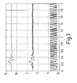
- FIG. 3 illustrates signals having interference to different extents.
- FIG. 4 illustrates an example embodiment of a radar device configured to perform the method according to the present invention.
- FIG. 5 illustrates another example embodiment of a radar device configured to perform the method according to the present invention.
- FIG. 6 is a flow chart illustrating an example method according to the present invention.
- FIG. 2 illustrates a motor vehicle 10 on which are arranged multiple radar sensors 12 .
- the radar sensors are connected to one another over a bus concept and to control and monitoring units, in particular a unit 14 which is provided for supplying a parking aid and for detection of a blind spot, a unit 16 for the precrash function and a unit 18 for stop and go.
- FIG. 3 illustrates curves for signals picked up by a short-range radar device.
- the upper signal curve is without interference.
- the middle signal curve is influenced by a strong interference which is caused in the present case by a FMCW radar, for example.
- the lower signal is influenced by a very strong interference of the same type.
- FIG. 4 schematically illustrates the configuration of a sensor 20 which is used in short-range radar.
- a voltage e.g., 8 V
- This voltage is transformed in a DC-DC transformer, so that ultimately the power supply voltage, e.g., 5 V, is made available for the sensor components.
- a carrier frequency of 24 GHz, for example, is supplied by a local oscillator 26 .
- This local oscillator 26 is supplied with a bias voltage which is ultimately generated by a transformer 30 from pulses supplied by a clock pulse generator 28 .
- the pulses generated by clock pulse generator 28 may have a frequency of 5 MHz, for example, and are used for modulation of carrier signals supplied by local oscillator 26 .
- This modulation is performed in a transmission branch by switch 32 , which is switched by a pulse shaper 46 .
- Pulse shaper 46 is in turn controlled by the clock frequency of clock pulse generator 28 .
- the pulsed signals generated in this manner are sent out by antenna 34 . In the case of reflection of the signals sent out by antenna 34 , they are received by receiving antenna 36 .
- the signals are sent to two mixers 40 , 42 , a first mixer 40 supplying an I signal and a second mixer 42 delivering a Q signal.
- the received signals are mixed with the pulsed signals of local oscillator 26 , with this pulsing occurring over a switch 44 .
- the switch is controlled by a pulse generator 48 which outputs pulses delayed by a time delay At with respect to the pulses output by pulse generator 46 .
- This time delay is supplied by a time-delay circuit 50 .
- the time delay of time-delay circuit 50 is influenced by a microcontroller 52 which has a digital signal processor. This occurs through a first analog output 54 of microcontroller 52 .
- I and Q signals processed by an amplifier 56 are influenced by further variable amplification in amplifier 58 over a second analog output 60 .
- This variable amplifier 58 is influenced by a second analog output 60 of microcontroller 52 .
- the output signal of variable amplifier 58 is sent to an analog input 62 of microcontroller 52 .
- Microcontroller 52 communicates with electronic control unit 22 over an input-output bus 64 (I/O bus).
- the transmission branch of radar sensor 20 is deactivated as illustrated in FIG. 4 .
- no more transmission signals are sent out by sending antenna 34 .
- correlation pulses are still being sent by pulse generator 48 to the reception branch of radar sensor 20 .
- target information is still being received, it may be concluded that there is a false signal.
- static target information may be eliminated through software, e.g., in electronic control unit 22 . Deterministically variable targets may be eliminated through a different choice of the mid-frequency of local oscillator 26 or the pulse repetition frequency supplied by clock pulse generator 28 .
- sporadic signals may not be taken into account using only the measures described so far. This is taken into account by the fact that a continuous carrier is applied to mixers 40 , 42 , so the received signals are transformed to a lower frequency.
- the interference carrier frequency may be determined by detuning the carrier frequency.
- FIG. 5 illustrates a circuit which corresponds largely to the circuit illustrated in FIG. 4 .
- a notch filter 66 provided in the reception branch may be used to advantage in particular when there is monochromatic or almost monochromatic interference.
- the circuit illustrated in FIG. 5 is also equipped with a PLL circuit 68 and an additional mixer 70 . By tuning this PLL source 68 , the interference frequency may be determined, i.e., on the basis of the arrangement illustrated in FIG. 5, it is no longer necessary to detune the carrier frequency.
- FIG. 6 is a flow chart illustrating an example method according to the present invention.
- S 03 turn off transmitter; pulsed reception or continuous reception.
- step S 02 a check is performed in step S 02 to determine whether there are irregularities in reception or whether the sensor is blind.
- the noise amplitude is measured in a certain window. The analyzing position is selected so that the signal-to-noise ratio remains constant. An increase in the noise component may then be interpreted as detection of interference. If it is detected in step S 02 that there are no irregularities and the sensor is not blind, then the program sequence goes to normal operation. In the other case, i.e., there are irregularities or the sensor is blind, then the transmitter is deactivated in step S 03 . In addition, there is pulsed reception or continuous reception.
- step S 04 the interference is analyzed. Following that in step S 05 , an attempt is made to eliminate the interference. This may be done, for example, by changing the mid-frequency, by changing the pulse repetition frequency, by using a notch filter or by changing the modulation scheme. Interference signals may also be eliminated through software.
- step S 06 a check is performed to determine whether the interference has been eliminated. If this is the case, it is possible to switch to normal operation. In the other case, the measurement is declared invalid in step S 07 .
Abstract
Description
Claims (18)
Applications Claiming Priority (3)
Application Number | Priority Date | Filing Date | Title |
---|---|---|---|
DE10108582.6 | 2001-02-22 | ||
DE10108582A DE10108582A1 (en) | 2001-02-22 | 2001-02-22 | Method for detecting disturbed states of a radar device and radar device |
DE10108582 | 2001-02-22 |
Publications (2)
Publication Number | Publication Date |
---|---|
US20020130811A1 US20020130811A1 (en) | 2002-09-19 |
US6618003B2 true US6618003B2 (en) | 2003-09-09 |
Family
ID=7675144
Family Applications (1)
Application Number | Title | Priority Date | Filing Date |
---|---|---|---|
US10/080,651 Expired - Fee Related US6618003B2 (en) | 2001-02-22 | 2002-02-22 | Method of detecting interference conditions of a radar device and a radar device |
Country Status (3)
Country | Link |
---|---|
US (1) | US6618003B2 (en) |
EP (1) | EP1235078A3 (en) |
DE (1) | DE10108582A1 (en) |
Cited By (4)
Publication number | Priority date | Publication date | Assignee | Title |
---|---|---|---|---|
US6894641B2 (en) * | 2002-11-15 | 2005-05-17 | Mitsubishi Denki Kabushiki | Radar system mounted on vehicle |
US20050134502A1 (en) * | 2003-12-22 | 2005-06-23 | Tdk Corporation | Pulse wave radar device |
US20080094274A1 (en) * | 2005-05-16 | 2008-04-24 | Motoi Nakanishi | Radar |
EP4350383A1 (en) * | 2022-10-06 | 2024-04-10 | Nxp B.V. | Method and radar system for detecting targeted radar interference |
Families Citing this family (35)
Publication number | Priority date | Publication date | Assignee | Title |
---|---|---|---|---|
DE10142170A1 (en) * | 2001-08-29 | 2003-03-20 | Bosch Gmbh Robert | Pulsed radar acquiring immediate surroundings of vehicles, includes high frequency oscillator connected to pulse modulators for transmission and reception |
US7474705B2 (en) * | 2002-08-16 | 2009-01-06 | Wisair Ltd | Scalable ultra-wide band communication system |
DE10254982A1 (en) | 2002-11-26 | 2004-06-03 | Robert Bosch Gmbh | Method and device for adaptive power control |
JP2010002272A (en) * | 2008-06-19 | 2010-01-07 | Toyota Motor Corp | Axis adjustment method and axis adjustment device for radar device |
US8238863B2 (en) * | 2009-12-10 | 2012-08-07 | Qualcomm Incorporated | Methods and apparatuses for identifying and mitigating interference in a wireless signal |
EP2390679B1 (en) * | 2010-05-27 | 2012-10-03 | Mitsubishi Electric R&D Centre Europe B.V. | Automotive radar with radio-frequency interference avoidance |
US9008249B2 (en) | 2012-02-10 | 2015-04-14 | Qualcomm Incorporated | Detection and filtering of an undesired narrowband signal contribution in a wireless signal receiver |
US9065686B2 (en) | 2012-11-21 | 2015-06-23 | Qualcomm Incorporated | Spur detection, cancellation and tracking in a wireless signal receiver |
DE102016202805A1 (en) * | 2016-02-24 | 2017-08-24 | Bayerische Motoren Werke Aktiengesellschaft | Method and device for operating an environmental sensor of a vehicle |
US9846228B2 (en) | 2016-04-07 | 2017-12-19 | Uhnder, Inc. | Software defined automotive radar systems |
US10261179B2 (en) | 2016-04-07 | 2019-04-16 | Uhnder, Inc. | Software defined automotive radar |
WO2017175190A1 (en) | 2016-04-07 | 2017-10-12 | Uhnder, Inc. | Adaptive transmission and interference cancellation for mimo radar |
US9791551B1 (en) | 2016-04-25 | 2017-10-17 | Uhnder, Inc. | Vehicular radar system with self-interference cancellation |
EP3449272B1 (en) | 2016-04-25 | 2022-11-02 | Uhnder, Inc. | Vehicle radar system with a shared radar and communication system, and method for managing such a system in a vehicle |
US10573959B2 (en) | 2016-04-25 | 2020-02-25 | Uhnder, Inc. | Vehicle radar system using shaped antenna patterns |
WO2017187304A2 (en) | 2016-04-25 | 2017-11-02 | Uhnder, Inc. | Digital frequency modulated continuous wave radar using handcrafted constant envelope modulation |
WO2017187299A2 (en) | 2016-04-25 | 2017-11-02 | Uhnder, Inc. | Successive signal interference mitigation |
WO2017187306A1 (en) | 2016-04-25 | 2017-11-02 | Uhnder, Inc. | Adaptive filtering for fmcw interference mitigation in pmcw radar systems |
WO2017187278A1 (en) * | 2016-04-25 | 2017-11-02 | Uhnder, Inc. | Pmcw – pmcw interference mitigation |
US9753121B1 (en) | 2016-06-20 | 2017-09-05 | Uhnder, Inc. | Power control for improved near-far performance of radar systems |
WO2018051288A1 (en) | 2016-09-16 | 2018-03-22 | Uhnder, Inc. | Virtual radar configuration for 2d array |
JP6858523B2 (en) * | 2016-10-06 | 2021-04-14 | 京セラ株式会社 | Distance measuring device, distance measuring method and vehicle |
WO2018146530A1 (en) | 2017-02-10 | 2018-08-16 | Uhnder, Inc. | Reduced complexity fft-based correlation for automotive radar |
US11454697B2 (en) | 2017-02-10 | 2022-09-27 | Uhnder, Inc. | Increasing performance of a receive pipeline of a radar with memory optimization |
US10866306B2 (en) | 2017-02-10 | 2020-12-15 | Uhnder, Inc. | Increasing performance of a receive pipeline of a radar with memory optimization |
JP6881177B2 (en) * | 2017-09-15 | 2021-06-02 | 株式会社デンソー | Radar device |
US11105890B2 (en) | 2017-12-14 | 2021-08-31 | Uhnder, Inc. | Frequency modulated signal cancellation in variable power mode for radar applications |
US11656321B2 (en) * | 2018-07-23 | 2023-05-23 | Richwave Technology Corp. | Method of microwave motion detection with adaptive frequency control and related devices |
DE102018217395A1 (en) * | 2018-10-11 | 2020-04-16 | Robert Bosch Gmbh | Method for determining the value of radar measurement values for determining an occupancy status of a parking space |
US11474225B2 (en) | 2018-11-09 | 2022-10-18 | Uhnder, Inc. | Pulse digital mimo radar system |
US11681017B2 (en) | 2019-03-12 | 2023-06-20 | Uhnder, Inc. | Method and apparatus for mitigation of low frequency noise in radar systems |
DE102019214949A1 (en) * | 2019-09-27 | 2021-04-01 | Robert Bosch Gmbh | Method and device for recognizing an absorptive radome coating |
WO2021144711A2 (en) | 2020-01-13 | 2021-07-22 | Uhnder, Inc. | Method and system for intefrence management for digital radars |
JP2021092585A (en) * | 2021-02-26 | 2021-06-17 | 住友電気工業株式会社 | Radio wave sensor and detection program |
CN113835077B (en) * | 2021-11-23 | 2022-02-11 | 中国空气动力研究与发展中心计算空气动力研究所 | Search radar target detection method and system based on variable pulse repetition frequency |
Citations (10)
Publication number | Priority date | Publication date | Assignee | Title |
---|---|---|---|---|
US3979752A (en) * | 1974-07-12 | 1976-09-07 | Thomson-Csf | Pulse-type radar with modulated carrier frequency |
US4040057A (en) * | 1975-05-14 | 1977-08-02 | The Marconi Company Limited | Clutter filter for pulse doppler radar |
US4622555A (en) * | 1982-09-02 | 1986-11-11 | Motorola, Inc. | Coded pulse Doppler radar with clutter-adaptive modulation and method therefore |
US4717917A (en) * | 1985-06-26 | 1988-01-05 | Rockwell International Corporation | Alien radar suppression circuit |
US5565870A (en) * | 1993-06-28 | 1996-10-15 | Nissan Motor Co., Ltd. | Radar apparatus with determination of presence of target reflections |
US5764697A (en) * | 1992-07-15 | 1998-06-09 | Futaba Denshi Kogyo, K.K. | Transmitter for a radio control device |
US6049302A (en) * | 1999-05-04 | 2000-04-11 | Boeing North American | Pulsed doppler radar system with small intermediate frequency filters |
US6141371A (en) * | 1996-12-18 | 2000-10-31 | Raytheon Company | Jamming suppression of spread spectrum antenna/receiver systems |
US6148020A (en) * | 1996-03-22 | 2000-11-14 | Sanyo Electric Co., Ltd. | Method and device for frequency hopping communication by changing a carrier frequency |
US6208248B1 (en) * | 1999-01-28 | 2001-03-27 | Anro Engineering, Inc. | Quick response perimeter intrusion detection sensor |
Family Cites Families (5)
Publication number | Priority date | Publication date | Assignee | Title |
---|---|---|---|---|
GB821575A (en) * | 1957-03-01 | 1959-10-07 | Marconi Wireless Telegraph Co | Improvements in or relating to repetitive signal systems |
US3916406A (en) * | 1963-02-20 | 1975-10-28 | Us Navy | Jamming cancellation device |
US4901082A (en) * | 1988-11-17 | 1990-02-13 | Grumman Aerospace Corporation | Adaptive waveform radar |
JP2657020B2 (en) * | 1992-03-17 | 1997-09-24 | 富士通株式会社 | FM-CW radar device |
US5923280A (en) * | 1997-01-17 | 1999-07-13 | Automotive Systems Laboratory, Inc. | Vehicle collision radar with randomized FSK wave form |
-
2001
- 2001-02-22 DE DE10108582A patent/DE10108582A1/en not_active Withdrawn
- 2001-12-08 EP EP01129146A patent/EP1235078A3/en not_active Withdrawn
-
2002
- 2002-02-22 US US10/080,651 patent/US6618003B2/en not_active Expired - Fee Related
Patent Citations (10)
Publication number | Priority date | Publication date | Assignee | Title |
---|---|---|---|---|
US3979752A (en) * | 1974-07-12 | 1976-09-07 | Thomson-Csf | Pulse-type radar with modulated carrier frequency |
US4040057A (en) * | 1975-05-14 | 1977-08-02 | The Marconi Company Limited | Clutter filter for pulse doppler radar |
US4622555A (en) * | 1982-09-02 | 1986-11-11 | Motorola, Inc. | Coded pulse Doppler radar with clutter-adaptive modulation and method therefore |
US4717917A (en) * | 1985-06-26 | 1988-01-05 | Rockwell International Corporation | Alien radar suppression circuit |
US5764697A (en) * | 1992-07-15 | 1998-06-09 | Futaba Denshi Kogyo, K.K. | Transmitter for a radio control device |
US5565870A (en) * | 1993-06-28 | 1996-10-15 | Nissan Motor Co., Ltd. | Radar apparatus with determination of presence of target reflections |
US6148020A (en) * | 1996-03-22 | 2000-11-14 | Sanyo Electric Co., Ltd. | Method and device for frequency hopping communication by changing a carrier frequency |
US6141371A (en) * | 1996-12-18 | 2000-10-31 | Raytheon Company | Jamming suppression of spread spectrum antenna/receiver systems |
US6208248B1 (en) * | 1999-01-28 | 2001-03-27 | Anro Engineering, Inc. | Quick response perimeter intrusion detection sensor |
US6049302A (en) * | 1999-05-04 | 2000-04-11 | Boeing North American | Pulsed doppler radar system with small intermediate frequency filters |
Cited By (6)
Publication number | Priority date | Publication date | Assignee | Title |
---|---|---|---|---|
US6894641B2 (en) * | 2002-11-15 | 2005-05-17 | Mitsubishi Denki Kabushiki | Radar system mounted on vehicle |
US20050134502A1 (en) * | 2003-12-22 | 2005-06-23 | Tdk Corporation | Pulse wave radar device |
US7012562B2 (en) * | 2003-12-22 | 2006-03-14 | Tdk Corporation | Pulse wave radar device |
US20080094274A1 (en) * | 2005-05-16 | 2008-04-24 | Motoi Nakanishi | Radar |
US7460058B2 (en) * | 2005-05-16 | 2008-12-02 | Murata Manufacturing Co., Ltd. | Radar |
EP4350383A1 (en) * | 2022-10-06 | 2024-04-10 | Nxp B.V. | Method and radar system for detecting targeted radar interference |
Also Published As
Publication number | Publication date |
---|---|
EP1235078A2 (en) | 2002-08-28 |
DE10108582A1 (en) | 2002-09-05 |
US20020130811A1 (en) | 2002-09-19 |
EP1235078A3 (en) | 2003-03-26 |
Similar Documents
Publication | Publication Date | Title |
---|---|---|
US6618003B2 (en) | Method of detecting interference conditions of a radar device and a radar device | |
US6404381B1 (en) | Radar sensor device | |
US6535161B1 (en) | Loop powered radar rangefinder | |
JP3788322B2 (en) | Radar | |
US6867730B2 (en) | Method of interference suppression in a radar device and a radar device | |
US10386458B2 (en) | Radar signal processing device and method | |
US20160154104A1 (en) | Method for operating a surroundings-detection system of a vehicle | |
US7012561B2 (en) | Device and method for registering, detecting, and/or analyzing at least one object | |
US20090219190A1 (en) | Method and Device for Measuring the Distance and Relative Speed of Multiple Objects | |
US6509864B1 (en) | Distance measuring device and method for calibrating a distance measuring device | |
CN1210578C (en) | Device for detecting objects in the area surroundiong a vehicle | |
US6844842B2 (en) | Method for pulse width modulation of a radar system | |
JP2000019242A (en) | Radar device for vehicle | |
US20060220943A1 (en) | Device for measuring the distance and speed of objects | |
US10656242B2 (en) | Radar sensor | |
US20190064335A1 (en) | Apparatus and method for rf interference avoidance in an automotive detection system | |
JP2005515445A (en) | Sensor front end for vehicle approach speed sensor | |
US6804168B2 (en) | Method for measuring distance | |
JP2008089505A (en) | Radar device | |
US20120256778A1 (en) | Short-range vehicular radar system | |
JP4762739B2 (en) | Transceiver | |
US20200072973A1 (en) | Method for operating an ultrasonic sensor | |
US20020163465A1 (en) | Method for generating and analyzing radar pulses as well as a radar sensor | |
US20060220947A1 (en) | Compact low power consumption microwave distance sensor obtained by power measurement on a stimulated receiving oscillator | |
JPH02223884A (en) | Moving object detecting device |
Legal Events
Date | Code | Title | Description |
---|---|---|---|
AS | Assignment |
Owner name: ROBERT BOSCH GMBH, GERMANY Free format text: ASSIGNMENT OF ASSIGNORS INTEREST;ASSIGNORS:VOIGTLAENDER, KLAUS;SCHAUMANN, ARNO;REEL/FRAME:013005/0849;SIGNING DATES FROM 20020404 TO 20020408 |
|
FEPP | Fee payment procedure |
Free format text: PAYOR NUMBER ASSIGNED (ORIGINAL EVENT CODE: ASPN); ENTITY STATUS OF PATENT OWNER: LARGE ENTITY |
|
FPAY | Fee payment |
Year of fee payment: 4 |
|
FPAY | Fee payment |
Year of fee payment: 8 |
|
REMI | Maintenance fee reminder mailed | ||
LAPS | Lapse for failure to pay maintenance fees | ||
STCH | Information on status: patent discontinuation |
Free format text: PATENT EXPIRED DUE TO NONPAYMENT OF MAINTENANCE FEES UNDER 37 CFR 1.362 |
|
FP | Lapsed due to failure to pay maintenance fee |
Effective date: 20150909 |