US6617543B1 - Method of making pattern for decorative piece - Google Patents
Method of making pattern for decorative piece Download PDFInfo
- Publication number
- US6617543B1 US6617543B1 US10/179,185 US17918502A US6617543B1 US 6617543 B1 US6617543 B1 US 6617543B1 US 17918502 A US17918502 A US 17918502A US 6617543 B1 US6617543 B1 US 6617543B1
- Authority
- US
- United States
- Prior art keywords
- etching
- laser
- decorative piece
- laser beam
- recession
- Prior art date
- Legal status (The legal status is an assumption and is not a legal conclusion. Google has not performed a legal analysis and makes no representation as to the accuracy of the status listed.)
- Expired - Lifetime
Links
- 238000004519 manufacturing process Methods 0.000 title claims abstract description 21
- 238000005530 etching Methods 0.000 claims abstract description 10
- 239000000758 substrate Substances 0.000 claims abstract description 8
- 238000010329 laser etching Methods 0.000 claims abstract description 7
- 238000002347 injection Methods 0.000 claims description 9
- 239000007924 injection Substances 0.000 claims description 9
- 239000000463 material Substances 0.000 claims description 9
- 230000003247 decreasing effect Effects 0.000 claims 1
- 239000006185 dispersion Substances 0.000 abstract 1
- 239000002184 metal Substances 0.000 abstract 1
- 238000000465 moulding Methods 0.000 abstract 1
- 238000010586 diagram Methods 0.000 description 6
- 238000000034 method Methods 0.000 description 6
- 230000015572 biosynthetic process Effects 0.000 description 4
- 230000008878 coupling Effects 0.000 description 2
- 238000010168 coupling process Methods 0.000 description 2
- 238000005859 coupling reaction Methods 0.000 description 2
- 238000003825 pressing Methods 0.000 description 2
- 229910000831 Steel Inorganic materials 0.000 description 1
- 238000009826 distribution Methods 0.000 description 1
- 238000001746 injection moulding Methods 0.000 description 1
- 239000007769 metal material Substances 0.000 description 1
- 238000012986 modification Methods 0.000 description 1
- 230000004048 modification Effects 0.000 description 1
- 239000010959 steel Substances 0.000 description 1
- 238000006467 substitution reaction Methods 0.000 description 1
- 230000000007 visual effect Effects 0.000 description 1
Images


Classifications
-
- B—PERFORMING OPERATIONS; TRANSPORTING
- B44—DECORATIVE ARTS
- B44C—PRODUCING DECORATIVE EFFECTS; MOSAICS; TARSIA WORK; PAPERHANGING
- B44C1/00—Processes, not specifically provided for elsewhere, for producing decorative surface effects
- B44C1/22—Removing surface-material, e.g. by engraving, by etching
- B44C1/228—Removing surface-material, e.g. by engraving, by etching by laser radiation
-
- A—HUMAN NECESSITIES
- A44—HABERDASHERY; JEWELLERY
- A44B—BUTTONS, PINS, BUCKLES, SLIDE FASTENERS, OR THE LIKE
- A44B19/00—Slide fasteners
- A44B19/24—Details
- A44B19/26—Sliders
- A44B19/262—Pull members; Ornamental attachments for sliders
-
- B—PERFORMING OPERATIONS; TRANSPORTING
- B23—MACHINE TOOLS; METAL-WORKING NOT OTHERWISE PROVIDED FOR
- B23K—SOLDERING OR UNSOLDERING; WELDING; CLADDING OR PLATING BY SOLDERING OR WELDING; CUTTING BY APPLYING HEAT LOCALLY, e.g. FLAME CUTTING; WORKING BY LASER BEAM
- B23K26/00—Working by laser beam, e.g. welding, cutting or boring
- B23K26/36—Removing material
- B23K26/38—Removing material by boring or cutting
- B23K26/382—Removing material by boring or cutting by boring
- B23K26/384—Removing material by boring or cutting by boring of specially shaped holes
-
- B—PERFORMING OPERATIONS; TRANSPORTING
- B23—MACHINE TOOLS; METAL-WORKING NOT OTHERWISE PROVIDED FOR
- B23K—SOLDERING OR UNSOLDERING; WELDING; CLADDING OR PLATING BY SOLDERING OR WELDING; CUTTING BY APPLYING HEAT LOCALLY, e.g. FLAME CUTTING; WORKING BY LASER BEAM
- B23K26/00—Working by laser beam, e.g. welding, cutting or boring
- B23K26/36—Removing material
- B23K26/38—Removing material by boring or cutting
- B23K26/382—Removing material by boring or cutting by boring
- B23K26/389—Removing material by boring or cutting by boring of fluid openings, e.g. nozzles, jets
Definitions
- the present invention relates to a method of making patterns for decorative piece.
- the conventional decorative piece of a zipper generally adopts the plastic injection method to manufacture all kinds of integral patterns and styles, or pressing thin metallic plates to produce the desired patterns and lines.
- the decorative piece of the zipper regardless of its formation by plastic injection of non-metallic materials or by pressing thin metallic plates has patterns or lines with larger size, and even worse its precision cannot be improved.
- the texture of the material is hard and cold which gives a feeling of strangeness and lacks the soft warm touch.
- R.O.C. Patent Application No. 87113232 entitled “Method of making multi-color decorative piece for zipper head”
- Such method forms patterns by traditional plastic injection molding, and thus the patterns so formed have the limitation of fineness and are unable to meet the fineness requirement for the size of only 0.03 ⁇ 0.07 mm. Therefore, general steel mold is not able to produce patterns of such fineness.
- the primary objective of the present invention is to provide a method of making pattern for a decorative piece, using metallic plate as the substrate, etching by laser etching to form a small conical recession, and manufacturing by plastic injection to produce small pins on the plastic material which is elastic in nature so that it gives a soft touch feeling and friction when it is touched or squeezed.
- the secondary objective of the present invention is to provide a method of making patterns for a decorative piece, and the small conical pins so formed having the smallest diameter of only 0.07 mm.
- Another objective of the present invention is to provide a method of making patterns for decorative piece, and the decorative piece so formed having a plurality of small conical pins, gives a soft warm touch when it goes with the pulling plate of the zipper, and prevents slippery when force is applied. It thus enhances the visual feeling.
- FIGS. 1 a ⁇ 1 d are the schematic diagrams of the manufacturing procedure according to the present invention.
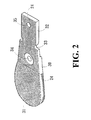
- FIG. 2 is a diagram showing the external appearance of the present invention.
- FIG. 3 is a side view diagram of the present invention.
- FIG. 4 is a schematic diagram enlarging a section of the present invention.
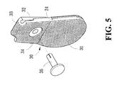
- FIG. 5 is a schematic diagram showing the coupling by a rivet according to the present invention.
- FIG. 6 is an illustrative diagram showing the coupling of the present invention with a zipper head.
- FIGS. 1 a ⁇ 1 d for a preferred embodiment of the present invention, which carves a substrate 10 of a mold by a laser beam 20 , and such laser beam 20 is shifted with an increment of x to cut an evenly distributed recession 11 with a specific depth on the a surface first, and then progressively lifts the laser head 2 to a specific height in order to enlarge the diameter of the emitting area of the laser beam 20 by means of the reflection from a convex lens.
- the depth cut by the laser beam 20 a is shallower than that produced by the laser beam 20 .
- Same procedure is repeated to etch at the same position with progressively shallower layer 23 .
- the laser head 20 is constantly lifted progressively and the depth of the emitting depth becomes shallower and the emitting area gets larger progressively to carve a small conical recession 12 .
- small conical recession 12 with the precision of only 0.03 ⁇ 0.07 mm is manufactured and formed by plastic injection of plastic material
- small pins 24 are formed by formation of plastic material, and thus gives a soft touch feeling and friction when it is squeezed or touched.
- method of making patterns for a decorative piece according to the present invention uses metallic plate for the substrate, and the following manufacture procedure is applied:
- the diameter of the laser beam becomes larger than the original laser beam diameter of 0.03 mm and at the same time, progressively lowers the depth to less than 0.5 mm by means of the reflection of a convex lens;
- the laser head is finally lifted to the height of about 0.5 mm according to the theory, and the laser beam expands the emitting area with the diameter of 0.35 mm via a convex lens. Therefore, it carves the small conical recess, and further forms the decorative piece having tiny pins on its surface, which gives a soft touch feeling and friction.
- a decorative piece 30 according to a preferred embodiment of the present invention having a small formation pattern comprises a holding section 31 , a curved section 23 , a thin plate section 33 , a rivet 34 , 35 , and a plurality of tiny conical pins 24 being formed equidistant with equal height, and the tip of the pin is only of the size of 0.07 mm, and the bottom of the cone of the recession 12 is only 0.03 mm.
- the injected material cannot be injected all the way to the close conical base during the injection formation. Therefore it can only produce a pin tip with the size of about 0.07 mm, and the distribution of the pins are very dense.
- the curved section 32 After the curved section 32 is folded into half by a rivet 35 , it can be coupled to an pulling plate 37 of a zipper to facilitating the pulling of the zipper and enhance the touching feeling as well as the friction to prevent slippery.
- the present invention produces fine conical pins to give a very soft touch and comfortable feeling and innovative artistic sense.
- the present invention adds value and distinctive texture to the whole, and also forms a decorative piece with trademark logos on it, which is particularly suitable for the promotion of products like garment, backpack, and shoes, etc.
- the present invention complies with the patentabilty, and hence submitted to the Patent and Trademark Office for review and granting of the commensurate patent rights.
Abstract
A method of making patterns for decorative piece, comprising the steps of using a metal plate as the molding substrate for laser etching; placing the mold substrate under a laser etching device, and cutting the substrate into a recession of appropriate depth. Further, the height of the laser head of the laser etching device is lifted, and then the dispersion of laser beam can be accomplished by means of a reflective lens. In the meantime, the depth of etching is reduced progressively, and the etching area is expanded along the path of previously cut recession. The manufacturing is made by progressively lifting the laser emitting head according to the theory described above.
Description
(a) Field of the Invention
The present invention relates to a method of making patterns for decorative piece.
(b) Description of the Prior Art
The conventional decorative piece of a zipper generally adopts the plastic injection method to manufacture all kinds of integral patterns and styles, or pressing thin metallic plates to produce the desired patterns and lines. However, the decorative piece of the zipper regardless of its formation by plastic injection of non-metallic materials or by pressing thin metallic plates has patterns or lines with larger size, and even worse its precision cannot be improved. Furthermore, the texture of the material is hard and cold which gives a feeling of strangeness and lacks the soft warm touch. As disclosed in R.O.C. Patent (Application No. 87113232) entitled “Method of making multi-color decorative piece for zipper head”, it shows a method of making a decorative piece fro zipper by plastic injection method. Such method forms patterns by traditional plastic injection molding, and thus the patterns so formed have the limitation of fineness and are unable to meet the fineness requirement for the size of only 0.03˜0.07 mm. Therefore, general steel mold is not able to produce patterns of such fineness.
Therefore, it is an object of the present invention to provide a method of making patterns for decorative piece which can obviate and mitigate the above-mentioned drawbacks.
The primary objective of the present invention is to provide a method of making pattern for a decorative piece, using metallic plate as the substrate, etching by laser etching to form a small conical recession, and manufacturing by plastic injection to produce small pins on the plastic material which is elastic in nature so that it gives a soft touch feeling and friction when it is touched or squeezed.
The secondary objective of the present invention is to provide a method of making patterns for a decorative piece, and the small conical pins so formed having the smallest diameter of only 0.07 mm.
Another objective of the present invention is to provide a method of making patterns for decorative piece, and the decorative piece so formed having a plurality of small conical pins, gives a soft warm touch when it goes with the pulling plate of the zipper, and prevents slippery when force is applied. It thus enhances the visual feeling.
The foregoing object and summary provide only a brief introduction to the present invention. To fully appreciate these and other objects of the present invention as well as the invention itself, all of which will become apparent to those skilled in the art, the following detailed description of the invention and the claims should be read in conjunction with the accompanying drawings. Throughout the specification and drawings identical reference numerals refer to identical or similar parts.
Many other advantages and features of the present invention will become manifest to those versed in the art upon making reference to the detailed description and the accompanying sheets of drawings in which a preferred structural embodiment incorporating the principles of the present invention is shown by way of illustrative example.
FIGS. 1a˜1 d are the schematic diagrams of the manufacturing procedure according to the present invention.
FIG. 2 is a diagram showing the external appearance of the present invention.
FIG. 3 is a side view diagram of the present invention.
FIG. 4 is a schematic diagram enlarging a section of the present invention.
FIG. 5 is a schematic diagram showing the coupling by a rivet according to the present invention.
FIG. 6 is an illustrative diagram showing the coupling of the present invention with a zipper head.
The following descriptions are of exemplary embodiments only, and are not intended to limit the scope, applicability or configuration of the invention in any way. Rather, the following description provides a convenient illustration for implementing exemplary embodiments of the invention. Various changes to the described embodiments may be made in the function and arrangement of the elements described without departing from the scope of the invention as set forth in the appended claims.
Please refer to FIGS. 1a˜1 d for a preferred embodiment of the present invention, which carves a substrate 10 of a mold by a laser beam 20, and such laser beam 20 is shifted with an increment of x to cut an evenly distributed recession 11 with a specific depth on the a surface first, and then progressively lifts the laser head 2 to a specific height in order to enlarge the diameter of the emitting area of the laser beam 20 by means of the reflection from a convex lens. At that time, the depth cut by the laser beam 20 a is shallower than that produced by the laser beam 20. Same procedure is repeated to etch at the same position with progressively shallower layer 23. The laser head 20 is constantly lifted progressively and the depth of the emitting depth becomes shallower and the emitting area gets larger progressively to carve a small conical recession 12. After the small conical recession 12 with the precision of only 0.03˜0.07 mm is manufactured and formed by plastic injection of plastic material, small pins 24 (as shown in FIGS. 2˜4) are formed by formation of plastic material, and thus gives a soft touch feeling and friction when it is squeezed or touched.
Therefore, method of making patterns for a decorative piece according to the present invention uses metallic plate for the substrate, and the following manufacture procedure is applied:
a. Putting the metallic plate mold material under the laser etching device;
b. Etching by the laser beam with the diameter of about 0.03 mm to produce a cut recession with an appropriate depth of about 0.5 mm;
c. Shifting the emitting position of the laser beam incrementally to form an evenly distributed recession on a surface;
d. Following the laser emitting position of the previous stage for etching the cut recession, and when the laser head is lifted to a specific height, the diameter of the laser beam becomes larger than the original laser beam diameter of 0.03 mm and at the same time, progressively lowers the depth to less than 0.5 mm by means of the reflection of a convex lens;
e. Repeating to lift the height of the laser head according to the previous theory, and shifting the emitting position of the laser beam incrementally to etch a small conical recession; and
f. Performing the plastic injection manufacturing to produce small pins of plastic material, and each pin is elastic and gives a soft touch to the decorative piece when it is touched or squeezed.
The laser head is finally lifted to the height of about 0.5 mm according to the theory, and the laser beam expands the emitting area with the diameter of 0.35 mm via a convex lens. Therefore, it carves the small conical recess, and further forms the decorative piece having tiny pins on its surface, which gives a soft touch feeling and friction.
Please refer to FIGS. 2˜4. A decorative piece 30 according to a preferred embodiment of the present invention having a small formation pattern comprises a holding section 31, a curved section 23, a thin plate section 33, a rivet 34, 35, and a plurality of tiny conical pins 24 being formed equidistant with equal height, and the tip of the pin is only of the size of 0.07 mm, and the bottom of the cone of the recession 12 is only 0.03 mm. However, the injected material cannot be injected all the way to the close conical base during the injection formation. Therefore it can only produce a pin tip with the size of about 0.07 mm, and the distribution of the pins are very dense. After the curved section 32 is folded into half by a rivet 35, it can be coupled to an pulling plate 37 of a zipper to facilitating the pulling of the zipper and enhance the touching feeling as well as the friction to prevent slippery.
In summation to the above description, the present invention produces fine conical pins to give a very soft touch and comfortable feeling and innovative artistic sense. Compared with the plastic injection manufacturing method for conventional decorative piece, the present invention adds value and distinctive texture to the whole, and also forms a decorative piece with trademark logos on it, which is particularly suitable for the promotion of products like garment, backpack, and shoes, etc.
The present invention complies with the patentabilty, and hence submitted to the Patent and Trademark Office for review and granting of the commensurate patent rights.
It will be understood that each of the elements described above, or two or more together may also find a useful application in other types of methods differing from the type described above.
While certain novel features of this invention have been shown and described and are pointed out in the annexed claim, it is not intended to be limited to the details above, since it will be understood that various omissions, modifications, substitutions and changes in the forms and details of the device illustrated and in its operation can be made by those skilled in the art without departing in any way from the spirit of the present invention.
Claims (4)
1. A method of making pattern for decorative piece, comprising the steps of: using a metallic plate as the substrate for a mold; etching the metallic plate with laser beam by incrementally moving the emitting position of the laser beam; cutting the metallic plate to form an even recession with a specific depth, and the laser head being progressively lifted to a specific distance to expand the emitting area by the increased diameter of laser beam, and in the meantime, the cut depth being decreased progressively; constantly lifting the position of the etching head and etching the same position on the metallic plate with a relatively shallower depth; and the etching with expanded area etching a conical recession on the substrate of the mold; and forming a plurality of small pins on a plastic material by plastic injection.
2. A method of making pattern for decorative piece as claimed in claim 1 , wherein said laser beam having an emitting diameter of 0.03 mm for the first time laser etching.
3. A method of making pattern for decorative piece as claimed in claim 1 , wherein said laser beam cutting the recession in the depth of approximately 0.5 mm for the first time laser etching.
4. A method of making pattern for decorative piece as claimed in claim 1 , wherein said plastic material is elastic.
Applications Claiming Priority (2)
| Application Number | Priority Date | Filing Date | Title |
|---|---|---|---|
| TW91107270A | 2002-04-11 | ||
| TW91107270 | 2002-04-11 |
Publications (1)
| Publication Number | Publication Date |
|---|---|
| US6617543B1 true US6617543B1 (en) | 2003-09-09 |
Family
ID=27787129
Family Applications (1)
| Application Number | Title | Priority Date | Filing Date |
|---|---|---|---|
| US10/179,185 Expired - Lifetime US6617543B1 (en) | 2002-04-11 | 2002-06-26 | Method of making pattern for decorative piece |
Country Status (1)
| Country | Link |
|---|---|
| US (1) | US6617543B1 (en) |
Cited By (7)
| Publication number | Priority date | Publication date | Assignee | Title |
|---|---|---|---|---|
| US20050087521A1 (en) * | 2003-10-28 | 2005-04-28 | Shih-Sheng Yang | Method of making patterns for decorative piece |
| US20070262493A1 (en) * | 2006-05-12 | 2007-11-15 | Universal Trim Supply Co., Ltd. | Method for forming a fine embossed pattern on a surface of a fastener member |
| US20110048254A1 (en) * | 2009-08-26 | 2011-03-03 | Oliver Espe | Method and device for producing a surface structure for a metallic press plate, endless belt or embossing roller |
| US9474327B2 (en) | 2013-08-19 | 2016-10-25 | Nike, Inc. | Sole structure masters, sole structure molds and sole structures having indicia and/or texture |
| US20170135446A1 (en) * | 2015-11-12 | 2017-05-18 | Patricia Behrend | Interchangeable zipper grip |
| US9669572B2 (en) | 2014-02-07 | 2017-06-06 | Duraflex Hong Kong Limited | Method for molding a decorative zipper pull and mold for a zipper pull |
| US10710200B2 (en) * | 2017-05-23 | 2020-07-14 | Sakai Display Products Corporation | Method for producing device support base and laser cleaning apparatus |
Citations (22)
| Publication number | Priority date | Publication date | Assignee | Title |
|---|---|---|---|---|
| DE237972C (en) * | ||||
| US3715734A (en) * | 1970-11-12 | 1973-02-06 | J Fajans | Memory storage device and method of making the same |
| US4843207A (en) * | 1985-01-17 | 1989-06-27 | Vyskumny A Vyvojovy Ustav Sklarsky | Method and apparatus for selective creation of a decor on hollow axially-symmetric products by a laser beam |
| US5206496A (en) * | 1990-08-15 | 1993-04-27 | United Distillers, Plc | Sub-surface marking |
| US5268862A (en) * | 1989-04-25 | 1993-12-07 | The Regents Of The Unversity Of California | Three-dimensional optical memory |
| US5575936A (en) * | 1992-12-18 | 1996-11-19 | Firebird Traders Ltd. | Process and apparatus for etching an image within a solid article |
| US5637244A (en) * | 1993-05-13 | 1997-06-10 | Podarok International, Inc. | Method and apparatus for creating an image by a pulsed laser beam inside a transparent material |
| US5653900A (en) * | 1991-01-17 | 1997-08-05 | United Distillers Plc | Dynamic laser marking |
| US5656186A (en) * | 1994-04-08 | 1997-08-12 | The Regents Of The University Of Michigan | Method for controlling configuration of laser induced breakdown and ablation |
| US5786560A (en) * | 1995-03-31 | 1998-07-28 | Panasonic Technologies, Inc. | 3-dimensional micromachining with femtosecond laser pulses |
| US5886318A (en) * | 1995-11-03 | 1999-03-23 | Vasiliev; Anatoly Valentinovich | Method for laser-assisted image formation in transparent objects |
| US6087617A (en) * | 1996-05-07 | 2000-07-11 | Troitski; Igor Nikolaevich | Computer graphics system for generating an image reproducible inside optically transparent material |
| US6231196B1 (en) * | 1997-03-27 | 2001-05-15 | Precision Laser Marking, Inc. | Laser marking process and products |
| US6322958B1 (en) * | 1998-11-26 | 2001-11-27 | Sumitomo Heavy Industries Ltd. | Laser marking method and apparatus, and marked member |
| US6333485B1 (en) * | 1998-12-11 | 2001-12-25 | International Business Machines Corporation | Method for minimizing sample damage during the ablation of material using a focused ultrashort pulsed beam |
| US6333486B1 (en) * | 2000-04-25 | 2001-12-25 | Igor Troitski | Method and laser system for creation of laser-induced damages to produce high quality images |
| US6392683B1 (en) * | 1997-09-26 | 2002-05-21 | Sumitomo Heavy Industries, Ltd. | Method for making marks in a transparent material by using a laser |
| US6399914B1 (en) * | 2000-07-10 | 2002-06-04 | Igor Troitski | Method and laser system for production of high quality laser-induced damage images by using material processing made before and during image creation |
| US6417485B1 (en) * | 2000-05-30 | 2002-07-09 | Igor Troitski | Method and laser system controlling breakdown process development and space structure of laser radiation for production of high quality laser-induced damage images |
| US6423162B1 (en) * | 1999-07-02 | 2002-07-23 | The University Of Tennesse Research Corporation | Method for producing decorative appearing bumper surfaces |
| US6426480B1 (en) * | 2000-08-30 | 2002-07-30 | Igor Troitski | Method and laser system for production of high quality single-layer laser-induced damage portraits inside transparent material |
| US6490299B1 (en) * | 2000-07-20 | 2002-12-03 | Troitski | Method and laser system for generating laser radiation of specific temporal shape for production of high quality laser-induced damage images |
-
2002
- 2002-06-26 US US10/179,185 patent/US6617543B1/en not_active Expired - Lifetime
Patent Citations (22)
| Publication number | Priority date | Publication date | Assignee | Title |
|---|---|---|---|---|
| DE237972C (en) * | ||||
| US3715734A (en) * | 1970-11-12 | 1973-02-06 | J Fajans | Memory storage device and method of making the same |
| US4843207A (en) * | 1985-01-17 | 1989-06-27 | Vyskumny A Vyvojovy Ustav Sklarsky | Method and apparatus for selective creation of a decor on hollow axially-symmetric products by a laser beam |
| US5268862A (en) * | 1989-04-25 | 1993-12-07 | The Regents Of The Unversity Of California | Three-dimensional optical memory |
| US5206496A (en) * | 1990-08-15 | 1993-04-27 | United Distillers, Plc | Sub-surface marking |
| US5653900A (en) * | 1991-01-17 | 1997-08-05 | United Distillers Plc | Dynamic laser marking |
| US5575936A (en) * | 1992-12-18 | 1996-11-19 | Firebird Traders Ltd. | Process and apparatus for etching an image within a solid article |
| US5637244A (en) * | 1993-05-13 | 1997-06-10 | Podarok International, Inc. | Method and apparatus for creating an image by a pulsed laser beam inside a transparent material |
| US5656186A (en) * | 1994-04-08 | 1997-08-12 | The Regents Of The University Of Michigan | Method for controlling configuration of laser induced breakdown and ablation |
| US5786560A (en) * | 1995-03-31 | 1998-07-28 | Panasonic Technologies, Inc. | 3-dimensional micromachining with femtosecond laser pulses |
| US5886318A (en) * | 1995-11-03 | 1999-03-23 | Vasiliev; Anatoly Valentinovich | Method for laser-assisted image formation in transparent objects |
| US6087617A (en) * | 1996-05-07 | 2000-07-11 | Troitski; Igor Nikolaevich | Computer graphics system for generating an image reproducible inside optically transparent material |
| US6231196B1 (en) * | 1997-03-27 | 2001-05-15 | Precision Laser Marking, Inc. | Laser marking process and products |
| US6392683B1 (en) * | 1997-09-26 | 2002-05-21 | Sumitomo Heavy Industries, Ltd. | Method for making marks in a transparent material by using a laser |
| US6322958B1 (en) * | 1998-11-26 | 2001-11-27 | Sumitomo Heavy Industries Ltd. | Laser marking method and apparatus, and marked member |
| US6333485B1 (en) * | 1998-12-11 | 2001-12-25 | International Business Machines Corporation | Method for minimizing sample damage during the ablation of material using a focused ultrashort pulsed beam |
| US6423162B1 (en) * | 1999-07-02 | 2002-07-23 | The University Of Tennesse Research Corporation | Method for producing decorative appearing bumper surfaces |
| US6333486B1 (en) * | 2000-04-25 | 2001-12-25 | Igor Troitski | Method and laser system for creation of laser-induced damages to produce high quality images |
| US6417485B1 (en) * | 2000-05-30 | 2002-07-09 | Igor Troitski | Method and laser system controlling breakdown process development and space structure of laser radiation for production of high quality laser-induced damage images |
| US6399914B1 (en) * | 2000-07-10 | 2002-06-04 | Igor Troitski | Method and laser system for production of high quality laser-induced damage images by using material processing made before and during image creation |
| US6490299B1 (en) * | 2000-07-20 | 2002-12-03 | Troitski | Method and laser system for generating laser radiation of specific temporal shape for production of high quality laser-induced damage images |
| US6426480B1 (en) * | 2000-08-30 | 2002-07-30 | Igor Troitski | Method and laser system for production of high quality single-layer laser-induced damage portraits inside transparent material |
Non-Patent Citations (5)
| Title |
|---|
| Efimov et al. "Photoinization of silicate glasses to IR femtosecodn pulses." Journal of Non-Crystalline Solids. v 253. 1999. pp 58-67.* * |
| Skuja et al. "Laser-induced color centers in silica." Laser-Induced Damage in Optical Materials. 2000. pp 155-163. * |
| Troitski, "Image Recording by Laser-induced damages." Optical Memory and Neural Networks. pp. 233-238. vol. 9, No. 4. 200.* * |
| Troitski, "Systems for creation of laser-induced images and problems of their optimization." Laser-Induced Damage in Optical Materials. 1999. pp. 489-499.* * |
| Troski, "Experience of creation of laser-induced damage images." Laser-Induced Damage in Optical Materials.1999. pp. 479-488..* * |
Cited By (10)
| Publication number | Priority date | Publication date | Assignee | Title |
|---|---|---|---|---|
| US20050087521A1 (en) * | 2003-10-28 | 2005-04-28 | Shih-Sheng Yang | Method of making patterns for decorative piece |
| JP2005132109A (en) * | 2003-10-28 | 2005-05-26 | Shih-Sheng Yang | Method for manufacturing mold for plastic molding and method for producing pattern on plastic molded article |
| JP4489556B2 (en) * | 2003-10-28 | 2010-06-23 | 士聖 楊 | Method for producing mold for plastic molding and method for producing pattern of plastic molded product |
| US20070262493A1 (en) * | 2006-05-12 | 2007-11-15 | Universal Trim Supply Co., Ltd. | Method for forming a fine embossed pattern on a surface of a fastener member |
| US20110048254A1 (en) * | 2009-08-26 | 2011-03-03 | Oliver Espe | Method and device for producing a surface structure for a metallic press plate, endless belt or embossing roller |
| US9446622B2 (en) * | 2009-08-26 | 2016-09-20 | Hueck Rheinische Gmbh | Method and device for producing a surface structure for a metallic press plate, endless belt or embossing roller |
| US9474327B2 (en) | 2013-08-19 | 2016-10-25 | Nike, Inc. | Sole structure masters, sole structure molds and sole structures having indicia and/or texture |
| US9669572B2 (en) | 2014-02-07 | 2017-06-06 | Duraflex Hong Kong Limited | Method for molding a decorative zipper pull and mold for a zipper pull |
| US20170135446A1 (en) * | 2015-11-12 | 2017-05-18 | Patricia Behrend | Interchangeable zipper grip |
| US10710200B2 (en) * | 2017-05-23 | 2020-07-14 | Sakai Display Products Corporation | Method for producing device support base and laser cleaning apparatus |
Similar Documents
| Publication | Publication Date | Title |
|---|---|---|
| US20050087521A1 (en) | Method of making patterns for decorative piece | |
| US6617543B1 (en) | Method of making pattern for decorative piece | |
| CN104486964B (en) | Stealthy base and its implementation and instrument | |
| WO2008102487A1 (en) | Sheet having uneven pattern formed thereon and method for production thereof | |
| US8850686B2 (en) | Method for patterning surface of metal object and the metal object | |
| JP2017136770A (en) | Decorative panel and manufacturing method thereof | |
| US20090181214A1 (en) | Fastener structure with a fine pattern on a surface thereof | |
| US6772580B2 (en) | Decorative, diamond-cut jewelry surface | |
| JP2008137613A (en) | Tire | |
| KR101946125B1 (en) | inlay method of jade products | |
| US958641A (en) | Method of producing ornamental articles. | |
| US2161549A (en) | Decorated article | |
| CN102290273A (en) | Dual-color keycap and manufacturing method thereof | |
| JP3144866U (en) | Mold for manufacturing raw materials | |
| US5374805A (en) | Method for making a novelty item and the novelty item therefrom | |
| CN217408029U (en) | Rotatable ornament | |
| US222580A (en) | Improvement in relief j ewelry | |
| CN219661090U (en) | Gold ornaments's many diamonds mosaic structure | |
| KR101189285B1 (en) | pattern forming method of accessory | |
| KR100344904B1 (en) | Processing method of accessories and accessories | |
| CN211138883U (en) | Decoration piece | |
| CN108312642A (en) | Paper structure and the production method for being formed on its surface groove pattern | |
| USD983601S1 (en) | Cookware with surface ornamentation | |
| CN219661091U (en) | Gold ornaments inlay and bore structure | |
| KR102566920B1 (en) | Manufacturing equipment for products and complex products (variants) |
Legal Events
| Date | Code | Title | Description |
|---|---|---|---|
| STCF | Information on status: patent grant |
Free format text: PATENTED CASE |
|
| RF | Reissue application filed |
Effective date: 20050527 |
|
| FPAY | Fee payment |
Year of fee payment: 4 |
|
| FPAY | Fee payment |
Year of fee payment: 8 |
|
| FPAY | Fee payment |
Year of fee payment: 12 |