US6613459B1 - Master magnetic information carrier, fabrication method thereof, and a method for manufacturing a magnetic recording medium - Google Patents
Master magnetic information carrier, fabrication method thereof, and a method for manufacturing a magnetic recording medium Download PDFInfo
- Publication number
- US6613459B1 US6613459B1 US09/617,357 US61735700A US6613459B1 US 6613459 B1 US6613459 B1 US 6613459B1 US 61735700 A US61735700 A US 61735700A US 6613459 B1 US6613459 B1 US 6613459B1
- Authority
- US
- United States
- Prior art keywords
- resin
- base plate
- surface portion
- magnetic
- magnetic films
- Prior art date
- Legal status (The legal status is an assumption and is not a legal conclusion. Google has not performed a legal analysis and makes no representation as to the accuracy of the status listed.)
- Expired - Fee Related, expires
Links
- 238000000034 method Methods 0.000 title claims abstract description 72
- 238000004519 manufacturing process Methods 0.000 title claims description 36
- 229920005989 resin Polymers 0.000 claims abstract description 209
- 239000011347 resin Substances 0.000 claims abstract description 209
- 238000003825 pressing Methods 0.000 claims abstract description 17
- 238000000059 patterning Methods 0.000 claims abstract description 12
- 238000010438 heat treatment Methods 0.000 claims abstract description 4
- 239000000758 substrate Substances 0.000 claims description 74
- 230000001681 protective effect Effects 0.000 claims description 35
- 239000000314 lubricant Substances 0.000 claims description 25
- 239000000463 material Substances 0.000 claims description 15
- OKTJSMMVPCPJKN-UHFFFAOYSA-N Carbon Chemical compound [C] OKTJSMMVPCPJKN-UHFFFAOYSA-N 0.000 claims description 13
- 238000009826 distribution Methods 0.000 claims description 11
- 229910052799 carbon Inorganic materials 0.000 claims description 10
- 239000012530 fluid Substances 0.000 claims description 9
- 238000013459 approach Methods 0.000 claims description 8
- 230000003014 reinforcing effect Effects 0.000 claims description 5
- 230000001678 irradiating effect Effects 0.000 claims description 3
- 229910003460 diamond Inorganic materials 0.000 claims 3
- 239000010432 diamond Substances 0.000 claims 3
- 230000008569 process Effects 0.000 abstract description 30
- 239000002245 particle Substances 0.000 abstract description 15
- 239000000126 substance Substances 0.000 abstract description 13
- 239000000356 contaminant Substances 0.000 abstract description 12
- 238000010030 laminating Methods 0.000 abstract 1
- XUIMIQQOPSSXEZ-UHFFFAOYSA-N Silicon Chemical compound [Si] XUIMIQQOPSSXEZ-UHFFFAOYSA-N 0.000 description 18
- 229910052710 silicon Inorganic materials 0.000 description 18
- 239000010703 silicon Substances 0.000 description 18
- 239000007789 gas Substances 0.000 description 13
- 230000000694 effects Effects 0.000 description 11
- 239000007788 liquid Substances 0.000 description 10
- 238000000151 deposition Methods 0.000 description 9
- 230000004907 flux Effects 0.000 description 8
- 239000010410 layer Substances 0.000 description 8
- 238000004873 anchoring Methods 0.000 description 7
- 230000008021 deposition Effects 0.000 description 7
- 230000001050 lubricating effect Effects 0.000 description 7
- 239000002904 solvent Substances 0.000 description 7
- BGPVFRJUHWVFKM-UHFFFAOYSA-N N1=C2C=CC=CC2=[N+]([O-])C1(CC1)CCC21N=C1C=CC=CC1=[N+]2[O-] Chemical compound N1=C2C=CC=CC2=[N+]([O-])C1(CC1)CCC21N=C1C=CC=CC1=[N+]2[O-] BGPVFRJUHWVFKM-UHFFFAOYSA-N 0.000 description 6
- 230000005347 demagnetization Effects 0.000 description 6
- 229920002120 photoresistant polymer Polymers 0.000 description 6
- 230000002035 prolonged effect Effects 0.000 description 6
- 239000011248 coating agent Substances 0.000 description 5
- 238000000576 coating method Methods 0.000 description 5
- 238000004544 sputter deposition Methods 0.000 description 5
- IJGRMHOSHXDMSA-UHFFFAOYSA-N Atomic nitrogen Chemical compound N#N IJGRMHOSHXDMSA-UHFFFAOYSA-N 0.000 description 4
- 206010040844 Skin exfoliation Diseases 0.000 description 4
- 239000004215 Carbon black (E152) Substances 0.000 description 3
- KFZMGEQAYNKOFK-UHFFFAOYSA-N Isopropanol Chemical compound CC(C)O KFZMGEQAYNKOFK-UHFFFAOYSA-N 0.000 description 3
- UCKMPCXJQFINFW-UHFFFAOYSA-N Sulphide Chemical compound [S-2] UCKMPCXJQFINFW-UHFFFAOYSA-N 0.000 description 3
- 230000007547 defect Effects 0.000 description 3
- 238000007723 die pressing method Methods 0.000 description 3
- 238000005516 engineering process Methods 0.000 description 3
- 229930195733 hydrocarbon Natural products 0.000 description 3
- 150000002430 hydrocarbons Chemical class 0.000 description 3
- 238000000465 moulding Methods 0.000 description 3
- 238000004528 spin coating Methods 0.000 description 3
- 229920001187 thermosetting polymer Polymers 0.000 description 3
- XKRFYHLGVUSROY-UHFFFAOYSA-N Argon Chemical compound [Ar] XKRFYHLGVUSROY-UHFFFAOYSA-N 0.000 description 2
- 238000009825 accumulation Methods 0.000 description 2
- 230000008901 benefit Effects 0.000 description 2
- 238000000354 decomposition reaction Methods 0.000 description 2
- 238000001312 dry etching Methods 0.000 description 2
- 238000005530 etching Methods 0.000 description 2
- 230000002349 favourable effect Effects 0.000 description 2
- 239000012847 fine chemical Substances 0.000 description 2
- 239000010419 fine particle Substances 0.000 description 2
- 239000001257 hydrogen Substances 0.000 description 2
- 229910052739 hydrogen Inorganic materials 0.000 description 2
- 230000005415 magnetization Effects 0.000 description 2
- VNWKTOKETHGBQD-UHFFFAOYSA-N methane Chemical compound C VNWKTOKETHGBQD-UHFFFAOYSA-N 0.000 description 2
- 229910052757 nitrogen Inorganic materials 0.000 description 2
- 238000000206 photolithography Methods 0.000 description 2
- 238000005268 plasma chemical vapour deposition Methods 0.000 description 2
- 239000004065 semiconductor Substances 0.000 description 2
- 238000001179 sorption measurement Methods 0.000 description 2
- HEDRZPFGACZZDS-UHFFFAOYSA-N Chloroform Chemical compound ClC(Cl)Cl HEDRZPFGACZZDS-UHFFFAOYSA-N 0.000 description 1
- OTMSDBZUPAUEDD-UHFFFAOYSA-N Ethane Chemical compound CC OTMSDBZUPAUEDD-UHFFFAOYSA-N 0.000 description 1
- VGGSQFUCUMXWEO-UHFFFAOYSA-N Ethene Chemical compound C=C VGGSQFUCUMXWEO-UHFFFAOYSA-N 0.000 description 1
- 239000005977 Ethylene Substances 0.000 description 1
- UFHFLCQGNIYNRP-UHFFFAOYSA-N Hydrogen Chemical compound [H][H] UFHFLCQGNIYNRP-UHFFFAOYSA-N 0.000 description 1
- 239000004642 Polyimide Substances 0.000 description 1
- 230000009471 action Effects 0.000 description 1
- 229910045601 alloy Inorganic materials 0.000 description 1
- 239000000956 alloy Substances 0.000 description 1
- 229910052786 argon Inorganic materials 0.000 description 1
- QVGXLLKOCUKJST-UHFFFAOYSA-N atomic oxygen Chemical compound [O] QVGXLLKOCUKJST-UHFFFAOYSA-N 0.000 description 1
- 238000010276 construction Methods 0.000 description 1
- 238000005137 deposition process Methods 0.000 description 1
- 238000001035 drying Methods 0.000 description 1
- 239000000428 dust Substances 0.000 description 1
- 238000007667 floating Methods 0.000 description 1
- -1 for example Polymers 0.000 description 1
- 230000009477 glass transition Effects 0.000 description 1
- 229910002804 graphite Inorganic materials 0.000 description 1
- 239000010439 graphite Substances 0.000 description 1
- 150000002431 hydrogen Chemical class 0.000 description 1
- 230000007246 mechanism Effects 0.000 description 1
- 239000002184 metal Substances 0.000 description 1
- 239000011368 organic material Substances 0.000 description 1
- 239000001301 oxygen Substances 0.000 description 1
- 229910052760 oxygen Inorganic materials 0.000 description 1
- 229910000889 permalloy Inorganic materials 0.000 description 1
- 238000001020 plasma etching Methods 0.000 description 1
- 229920000515 polycarbonate Polymers 0.000 description 1
- 239000004417 polycarbonate Substances 0.000 description 1
- 229920005668 polycarbonate resin Polymers 0.000 description 1
- 239000004431 polycarbonate resin Substances 0.000 description 1
- 229920001721 polyimide Polymers 0.000 description 1
- 229920000098 polyolefin Polymers 0.000 description 1
- 229920005672 polyolefin resin Polymers 0.000 description 1
- 239000011241 protective layer Substances 0.000 description 1
- 230000001172 regenerating effect Effects 0.000 description 1
- 239000013077 target material Substances 0.000 description 1
- 238000005406 washing Methods 0.000 description 1
- 238000001039 wet etching Methods 0.000 description 1
Images


Classifications
-
- G—PHYSICS
- G11—INFORMATION STORAGE
- G11B—INFORMATION STORAGE BASED ON RELATIVE MOVEMENT BETWEEN RECORD CARRIER AND TRANSDUCER
- G11B5/00—Recording by magnetisation or demagnetisation of a record carrier; Reproducing by magnetic means; Record carriers therefor
- G11B5/62—Record carriers characterised by the selection of the material
- G11B5/64—Record carriers characterised by the selection of the material comprising only the magnetic material without bonding agent
-
- B—PERFORMING OPERATIONS; TRANSPORTING
- B82—NANOTECHNOLOGY
- B82Y—SPECIFIC USES OR APPLICATIONS OF NANOSTRUCTURES; MEASUREMENT OR ANALYSIS OF NANOSTRUCTURES; MANUFACTURE OR TREATMENT OF NANOSTRUCTURES
- B82Y10/00—Nanotechnology for information processing, storage or transmission, e.g. quantum computing or single electron logic
-
- G—PHYSICS
- G11—INFORMATION STORAGE
- G11B—INFORMATION STORAGE BASED ON RELATIVE MOVEMENT BETWEEN RECORD CARRIER AND TRANSDUCER
- G11B5/00—Recording by magnetisation or demagnetisation of a record carrier; Reproducing by magnetic means; Record carriers therefor
- G11B5/74—Record carriers characterised by the form, e.g. sheet shaped to wrap around a drum
- G11B5/743—Patterned record carriers, wherein the magnetic recording layer is patterned into magnetic isolated data islands, e.g. discrete tracks
-
- G—PHYSICS
- G11—INFORMATION STORAGE
- G11B—INFORMATION STORAGE BASED ON RELATIVE MOVEMENT BETWEEN RECORD CARRIER AND TRANSDUCER
- G11B5/00—Recording by magnetisation or demagnetisation of a record carrier; Reproducing by magnetic means; Record carriers therefor
- G11B5/84—Processes or apparatus specially adapted for manufacturing record carriers
- G11B5/855—Coating only part of a support with a magnetic layer
-
- G—PHYSICS
- G11—INFORMATION STORAGE
- G11B—INFORMATION STORAGE BASED ON RELATIVE MOVEMENT BETWEEN RECORD CARRIER AND TRANSDUCER
- G11B5/00—Recording by magnetisation or demagnetisation of a record carrier; Reproducing by magnetic means; Record carriers therefor
- G11B5/86—Re-recording, i.e. transcribing information from one magnetisable record carrier on to one or more similar or dissimilar record carriers
- G11B5/865—Re-recording, i.e. transcribing information from one magnetisable record carrier on to one or more similar or dissimilar record carriers by contact "printing"
-
- G—PHYSICS
- G11—INFORMATION STORAGE
- G11B—INFORMATION STORAGE BASED ON RELATIVE MOVEMENT BETWEEN RECORD CARRIER AND TRANSDUCER
- G11B5/00—Recording by magnetisation or demagnetisation of a record carrier; Reproducing by magnetic means; Record carriers therefor
- G11B5/48—Disposition or mounting of heads or head supports relative to record carriers ; arrangements of heads, e.g. for scanning the record carrier to increase the relative speed
- G11B5/58—Disposition or mounting of heads or head supports relative to record carriers ; arrangements of heads, e.g. for scanning the record carrier to increase the relative speed with provision for moving the head for the purpose of maintaining alignment of the head relative to the record carrier during transducing operation, e.g. to compensate for surface irregularities of the latter or for track following
- G11B5/596—Disposition or mounting of heads or head supports relative to record carriers ; arrangements of heads, e.g. for scanning the record carrier to increase the relative speed with provision for moving the head for the purpose of maintaining alignment of the head relative to the record carrier during transducing operation, e.g. to compensate for surface irregularities of the latter or for track following for track following on disks
- G11B5/59633—Servo formatting
-
- G—PHYSICS
- G11—INFORMATION STORAGE
- G11B—INFORMATION STORAGE BASED ON RELATIVE MOVEMENT BETWEEN RECORD CARRIER AND TRANSDUCER
- G11B5/00—Recording by magnetisation or demagnetisation of a record carrier; Reproducing by magnetic means; Record carriers therefor
- G11B5/74—Record carriers characterised by the form, e.g. sheet shaped to wrap around a drum
- G11B5/82—Disk carriers
Definitions
- the present invention relates to a master magnetic information carrier such as a master disk used in preformatted recording of servo signals, address signals or regenerative clock signals of a magnetic recording medium, in particular, relates to a master magnetic information carrier having embedded magnetic layers that records the servo signals and the like, and a fabrication method thereof.
- the invention also relates to a magnetic contact duplication technology in a manufacturing process of a magnetic recording medium.
- HDD hard disk drive
- recording and reproduction (or writing and reading) of data are processed while a magnetic head flies over a surface of a rotating magnetic recording disk by a floating mechanism called slider holding a flying height of several tens of nm.
- the bit information on the magnetic recording disk is stored in concentric data tracks on the disk.
- Read/write of the data is conducted by quickly moving and positioning the read/write head to the target data trace
- Each of concentric circles on the magnetic recording disk has preformatted fields recording in a certain angular interval the preformatted information including tracking servo signal for detecting relative position between the head and the data track, address signal or generative clock signal, and the data recording and reproducing head automatically detect its own position in a certain time interval.
- the preformatted information is written on the magnetic recording disk using a special writing apparatus called servo track writer after the disk is installed in a HDD, so that for the center of the writing signal of the preformatted information should not be off-centered from the disk center or the center of the head orbit.
- FIG. 10 ( a ) through FIG. 10 ( c ) and FIG. 11 ( a ) and FIG. 11 ( b ) illustrate the magnetic contact duplication technique.
- FIG. 11 ( a ) is a cross sectional view showing an initial demagnetization process where permanent magnet 2 is moved in a circumferential direction above the surface of the magnetic recording disk 1 . Since the structure of the magnetic recording disk 1 is well known, the figure simply shows a substrate 1 a and a magnetic layer 1 b laminated thereon. The magnetic layer 1 b is not magnetized in one direction in the beginning, and is magnetized in the initial magnetization step uniformly in one direction, a circumferential direction, by leakage flux of the permanent magnet 2 .
- the arrows in the magnetic layer 1 b represent the direction of demagnetization field A.
- the curved arrow in FIG. 10 ( a ) shows the moving path of the permanent magnet 2 .
- a master disk for magnetic contact duplication is disposed in position on the magnetic recording disk 1 to which initial demagnetization has been performed, as shown in FIG. 10 ( b ) and FIG. 1 ( b ).
- Embedded magnetic films 3 a which are Co-based soft-magnetic films, are discretely embedded in surface region of the master disk 3 , surrounded by surface portion 3 b of the substrate.
- Magnetic contact duplication is performed by moving the permanent magnet 4 on the master disk 3 , as shown in FIG. 10 ( c ) and FIG. 11 ( b ).
- the curved arrow in FIG. 10 ( c ) indicates the moving path of the permanent magnet 4 .
- the magnetic field in the duplication step is the leakage flux from the permanent magnet 4 , the direction of which is reversed from the demagnetization field A.
- the leakage flux pass through the surface portion 3 b of the substrate and reach the magnetic layer 1 b of the magnetic recording disk 1 and reverse the field direction of the demagnetization A to produce recording magnetization B with high coercive force.
- the leakage flux passes along the surface direction of the magnetic film so that magnetic resistance of the magnetic path is minimized. Since the leakage flux does not reach the magnetic layer 1 b of the magnetic recording disk 1 , the demagnetization A remains, thus a negative pattern of the pattern of the embedded magnetic film 3 a is magnetically transferred onto the magnetic recording disk 1 .
- the magnetic recording disk is not magnetized by leakage flux of the embedded magnetic film 3 a of the master disk 3 , but is selectively magnetized by the leakage flux from the permanent magnet 4 through the surface portion 3 b of the substrate, while the embedded magnetic films 3 a function as a magnetic contact duplication mask that shields parts of the leakage flux from the permanent magnet 4 .
- FIG. 12 ( a ) through FIG. 12 ( e ) show a method for manufacturing a master disk 3 having embedded magnetic films 3 a.
- photoresist of 1 ⁇ m thick is applied by spin-coating on a silicon substrate 3 c of about 500 ⁇ m thick, followed by patterning by means of photolithography commonly used in producing silicon semiconductor devices, to form an etching mask 5 , as shown in FIG. 12 ( a ). Then, grooves 6 of depth of about 500 nm are dug by dry-etching the surface of the silicon substrate 3 c by means of reactive plasma etching technique using reactive gas of methane trichloride, as shown in FIG. 12 ( b ).
- Co-based soft-magnetic film 7 of about 500 nm thick is deposited by sputtering on the substrate with the mask 5 left thereon, to form an embedded Co-based soft-magnetic film 7 in the dug groove 6 , as shown in FIG. 12 ( c ).
- the resultant substrate 3 c is dipped in solvent to remove the mask 5 and the Co-based magnetic film 7 thereon, remaining the Co-based soft-magnetic film 7 in the groove 6 as embedded magnetic films 3 a .
- a master disk 3 with a flat surface having embedded magnetic films 3 a is obtained.
- the master disk manufactured by the above-described manner involves the following problems.
- FIG. 12 ( c ) shows an ideal cross sectional structure in a deposition process of Co-based soft-magnetic film 7 , where every sputtered Co particle travels to the bottom surface of the groove 6 of the substrate 3 c with incident angle exactly perpendicular to the bottom surface and is not deposited on the inner side-wall of the groove 6 or side-wall of the mask 5 .
- the traveling particles include obliquely incident component as well as perpendicularly incident component, deposition occurs on the inner side-wall of the groove 6 and side-wall of the mask 5 , as illustrated in FIG. 12 ( e ), which is an enlarged cross section of the portion of FIG. 12 ( c ) enclosed by two-dot chain line.
- FIG. 12 ( f ) is an enlarged cross section of the portion enclosed by two-dot chain line in FIG. 12 ( d ).
- recesses 8 a and protrusions 8 b cause various problems. Because the surface of the magnetic recording disk 1 contacts the surface of the master disk 3 or become close proximity with several tens to several hundreds of ⁇ clearance between them in the magnetic contact duplication process, the protrusions 8 b cause the magnetic recording disk 1 to be transferred with flaws and gouges in the magnetic contact duplication process.
- the recesses 8 a on the surface of the master disk 3 also cause particles and chemical contaminants to be accumulated at the recesses. Those particles and chemical contaminants may be transferred to the magnetic recording disk 1 in certain probability after a large number of contact duplication operations.
- the master disk 3 has to be closest to or directly contacted with the magnetic recording disk 1 to enhance accuracy of the magnetic contact duplication, the surfaces of the embedded magnetic films 3 a and the silicon substrate 3 c deteriorate by wear, for example.
- the present invention features utilization of a resin substrate instead of a silicon substrate. That is, the master magnetic information carrier of the invention comprises embedded magnetic films surrounded by a surface portion of a resin substrate, the surface of the magnetic films being in a common plane with that of the surface portion of the resin substrate.
- the resin substrate After forming discrete and isolated magnetic films on the substrate, step portions between the magnetic films can be made even with the surface portion of the resin substrate.
- the embedded magnetic films are surrounded by the surface portion of the resin substrate to obtain a smooth and flat surface and to avoid the protrusion and recess that would appear around each circumference of the embedded magnetic films. As a result, generation of flaws and gouges on the magnetic recording disk and transfer of particles and chemical contaminants to the recording disk in the contact duplication process can be avoided.
- Material of the resin surface portion of the resin substrate may be the same as the material of the other portion of the resin substrate.
- the density in the resin surface portion is preferably higher than that in the other portion of the resin substrate, which enhances anchoring action with the embedded magnetic film and allows the use of a strong magnet for duplication.
- the density distribution in the resin surface portion is favorable where the density varies in the surface direction such that the density becomes higher as a position approaches nearer to the side-walls of the embedded magnetic films.
- the density distribution of the resin surface portion where the density varies in the depth direction such that the density becomes higher as a position approaches nearer to the surface of the resin surface portion. The both density distributions enhance anchoring effect with the embedded magnetic films and durability of the magnetic films.
- Material of the resin surface portion may be photo-setting resin.
- the resin surface portion made of the photo-setting resin may be formed after forming discrete and isolated magnetic films on a resin substrate, by applying fluid photo-setting resin and flattening it, followed by curing. Also in this construction, the embedded magnetic films are surrounded by the resin surface portion of the resin substrate to obtain smooth and flat surfaces and to avoid the protrusion and recess that would appear around each circumference of the embedded magnetic films. As a result, generation of flaws and gouges on the magnetic recording medium and transfer of particles and chemical contaminants to the recording medium in the contact duplication process can be avoided.
- a reinforcing substrate is laminated on the back surface of the resin substrate.
- a master magnetic information carrier of the invention may use a refractory substrate comprising a refractory base plate, such as silicon base plate.
- a master magnetic information carrier comprises an embedded magnetic films surrounded by resin surface portion of the refractory substrate, the surfaces of the magnetic films being in a common plane with the surface of the resin surface portion, wherein the material of the resin surface portion of the refractory substrate is thermo-setting resin. Since the refractory base plate is used in the substrate, material of the resin surface portion can be thermo-setting resin. Also in this configuration, the embedded magnetic films are surrounded by the resin surface portion to obtain a smooth and flat surfaces and to avoid protrusions and recesses that would appear around each circumference of the embedded magnetic films.
- the master magnetic information carrier of the invention features provision of a protective film covering the embedded magnetic film.
- the protective film reduces friction in the magnetic contact duplication process and prolongs life of contact duplication operations.
- the protective layer may be a double-layered film.
- the lower layer is a DLC (diamond-like carbon) film and the upper layer is a lubricant film.
- the configuration remarkably prolongs life of contact duplication.
- the protective film is a hydrogen-added DLC film, a film with higher hardness can be deposited than a pure DLC film.
- the protective film is a nitrogen-added DLC film, adsorption of corrosive gases, dominant component of which is sulfide, is effectively suppressed.
- the present invention further provides a method for manufacturing a master magnetic information carrier having embedded magnetic films surrounded by a resin surface portion of a resin substrate, the surface of the embedded magnetic films being in a common plane with the surface of the resin surface portion, the method comprising the steps of forming discrete and isolated magnetic films in a predetermined region by patterning a continuous magnetic film laminated on a surface of a resin base plate, and pressing the heated resin substrate from above the isolated magnetic films by a die.
- the resin surface portion is formed by a marking or stamping method, in which the surface region within the resin base plate itself is thermoplastically deformed. Therefore, the resin surface portion and the other portion of the resin substrate are in an integrated structure without any boundary in-between.
- the resin surface portion is denser than the other portion of the substrate because of the pressure molding adapted in the manufacturing method.
- the resin surface portion exhibits density distribution both in the surface direction or lateral direction and in the depth direction or vertical direction in the resin surface portion, which brings about the strong anchoring effect with the embedded magnetic films, eliminating risk of peeling off of the embedded magnetic films even when the magnetic force of the permanent magnet for magnetic contact duplication is strong.
- the manufacturing method of the invention may further comprise a step of coating the surface of the resin substrate with photo-setting resin film between the step of forming isolated magnetic film and the step of pressing the substrate with die, and also comprise a step of irradiating light from the back surface side of the resin substrate before releasing the die utilized in the pressing step.
- the resin surface portion with reduced strain and initial stress is obtained by the method.
- the recess portion of the die is adjusted to the position opposite the predetermined region for the magnetic film in the resin substrate and pushed down.
- the protrusion portion of the die first sink into the resin substrate, and then, the recess portion of the die catches the predetermined region within the recess portion of the die and presses the isolated magnetic films into the resin substrate. Consequently, the embedded magnetic films hardly drift relative to each other, and precise positioning of the embedded magnetic film is achieved.
- the region formed by the protrusion portion of the die is useful as an air vent groove.
- the present invention provides further method for manufacturing a master magnetic information carrier having an embedded magnetic films surrounded by a resin surface portion on a refractory base plate, the surfaces of the embedded magnetic films being in a common plane with the surface of the resin surface portion, the method comprising the steps of forming discrete and isolated magnetic films in a predetermined region by patterning a continuous magnetic film deposited on a surface of the refractory base plate, applying fluid thermosetting resin covering the isolated magnetic films on a refractory base plate, curing the fluid thermosetting setting resin by heating, and etching-back a film of the cured thermo-setting resin until a surfaces of the isolated magnetic films is exposed.
- the method proceeds with the sequence of forming the isolated magnetic films, covering the magnetic films with the thermo-setting resin film and curing, and etching-back the resin film. Therefore, the surfaces of the embedded magnetic films and the resin surface portion of the substrate can be made smooth and flat, to obtain a master magnetic information carrier free from protrusion and recess at the boundaries between the magnetic films and the resin surface portion.
- the invention further provides a method for manufacturing a magnetic recording medium including a preformatting step performing magnetic contact duplication from a master magnetic information carrier to a magnetic recording medium, wherein contact duplication is conducted with the master magnetic information carrier overlapped together with the magnetic recording medium, and the two articles immersed in liquid of a lubricant or exposed to vapor of a lubricant. Since friction is reduced with the liquid or vapor of the lubricant, prolonged life of contact duplication times is achieved even in a master magnetic information carrier without protective film.
- FIG. 1 ( a ) through FIG. 1 ( e ) are cross sectional views showing steps in the method for manufacturing a master disk according to the first embodiment of the invention.
- FIG. 2 ( a ) through FIG. 2 ( d ) are cross sectional views showing steps in the method for manufacturing a master disk according to the second embodiment of the invention.
- FIG. 3 ( a ) through FIG. 3 ( f ) are cross sectional views showing steps in the method for manufacturing a master disk according to the third embodiment of the invention.
- FIG. 4 is a cross sectional view showing a master disk according to the fourth embodiment of the invention.
- FIG. 5 is a cross sectional view showing a master disk according to the fifth embodiment of the invention.
- FIG. 6 is a cross sectional view showing a master disk according to the sixth embodiment of the invention.
- FIG. 7 is a cross sectional view showing a master disk according to the seventh embodiment of the invention.
- FIG. 8 is a cross sectional view showing a master disk according to the eighth embodiment of the invention.
- FIG. 9 is a cross sectional view showing the magnetic contact duplication process or preformatting process in the method for manufacturing a magnetic recording disk according to the invention.
- FIG. 10 ( a ) through FIG. 10 ( c ) are perspective views illustrating a preformatting process of a magnetic recording disk.
- FIG. 11 ( a ) and FIG. 11 ( b ) are cross sectional views illustrating a preformatting process of a magnetic recording disk.
- FIG. 12 ( a ) through FIG. 12 ( d ) are cross sectional views showing steps in the method for manufacturing a conventional master disk having embedded magnetic films.
- FIG. 12 ( e ) is an enlarged cross sectional view of the part ‘e’ in FIG. 12 ( c ).
- FIG. 12 ( f ) is an enlarged cross sectional view of the part ‘f’ in FIG. 12 ( d ).
- FIG. 1 ( a ) through FIG. 1 ( e ) are cross sectional views showing steps of manufacturing a master disk of the first embodiment of the invention.
- a resin base plate 10 is prepared having diameter of about 4 inches and thickness of 0.5 to 1 mm, formed of polycarbonate resin or polyolefin resin using a molding machine.
- a soft-magnetic film 11 of a Co-base alloy or Permalloy having thickness of 500 to 5000 ⁇ is formed by a sputtering method on the surface of the resin base plate.
- a photolithography process commonly used in fabricating semiconductor devices is carried out, in which photoresist is applied using spin-coater followed by drying, and then, patterning of a photoresist is performed by exposure through a photomask.
- the patterned photoresist is used as a mask for patterning like FIG. 1 ( b ) by means of dry or wet etching, to obtain a pattern of discrete and isolated magnetic films 11 a which is a structure to become embedded magnetic films.
- the region occupied by a plurality of isolated magnetic films 11 a corresponds to the preformatted region F of a magnetic recording disk.
- the region between adjacent preformatted regions F, F corresponds to the data region, i.e., unformatted region, of a magnetic recording disk.
- a mold or a die 12 having protrusion portions and recess portions is positioned opposite to the resin base plate with magnetic films thereon, as shown in FIG. 1 ( c ).
- the die 12 has a recess portion 12 a opposite the region bearing the isolated magnetic films and corresponding to a preformatted region F, and a protrusion portion 12 b opposite the region corresponding to a data region D. Height of the step between the protrusion portion and the recess portion is larger than the thickness of the isolated magnetic film 11 a.
- the surface of the resin base plate 10 is pressed by the die 12 heated up to the softening temperature of the resin, as shown in FIG. 1 ( d ).
- the protrusion portion 12 b of the die 12 starts to sink into the surface region of the resin base plate corresponding to the data region D.
- the recess portion 12 a pushes the isolated magnetic films 11 a into the resin base plate.
- the die 12 is released, to obtain a master disk 15 shown in FIG. 1 ( e ).
- the region of the master disk 15 corresponding to data region D provides an air vent groove 10 a , useful for attracting a recording disk in a magnetic contact duplication process.
- the region of the master disk corresponding to preformatted region F forms a trapezoid and comprises embedded magnetic films 11 b having surfaces in a common plane with the surface of the resin surface portion 10 b . Since the master disk 15 is a mold product made by pressing the die 12 into the thermally softened resin base plate 10 , the embedded magnetic films 11 b and the surrounding resin surface portion 10 b are intimately joined and irregularity at the boundary region is minimized.
- the surface of the master disk 15 corresponding to the preformatted region F is sufficiently smooth and flat. As a result, generation of flaws and gouges on the magnetic recording medium and transfer of particles and chemical contaminants to the recording medium in the contact duplication process can be avoided.
- the resin surface portion 10 b is formed by thermo-plastically stamping the surface of the resin substrate 10 itself, and therefore, continues to the resin base plate without any boundary.
- the resin surface portion 10 b is denser than the other portion of the substrate.
- the density within the resin surface portion 10 b also varies in surface (lateral) direction such that the density increases as the position approaches the side-walls of the embedded magnetic films 11 b .
- the density in the resin surface portion 10 b exhibits the distribution such that the density increases as the position approaches the surface of the resin surface portion.
- the resin surface portion 10 b seals the embedded magnetic films 11 b with high adhesivity, resulting to fairly strong anchoring effect with the embedded magnetic films 11 b .
- the effect eliminates troubles such as peeling off of the embedded magnetic films even when the magnetic force of a permanent magnet for duplication is strong.
- the protrusion portion 12 b of the die 12 first sink into the portion of the resin base plate corresponding to the data region D, and then the recess portion 12 a catches the limited region of the resin base plate corresponding to the preformatted region F and presses the isolated magnetic films 11 a into the resin base plate.
- the embedded magnetic films 11 b are not likely to laterally shift with respect to each other, and precise positioning of the embedded magnetic films is achieved.
- the portion formed by the protrusion portion of the die can be used as an air vent groove.
- FIG. 2 ( a ) through FIG. 2 ( e ) are cross sectional views showing steps of a method for manufacturing a master disk according to the second embodiment of the invention.
- discrete and isolated magnetic films 11 a are formed on the resin base plate 10 , as shown in FIG. 2 ( a ).
- a photo-setting resin film 16 are formed having a enough thickness to cover the isolated magnetic films by coating using a spin-coater, before a pressing step with the die 12 , as shown in FIG. 2 ( b ).
- the pressing step using die 12 is conducted.
- the die 12 is heated up to the glass transition temperature of the resin base plate 10 similarly to the first aspect of embodiment.
- the photo-setting resin film 16 is subjected to ultraviolet light irradiation from the back side of the resin base plate to cure the resin film that has been formerly fluid state, as shown in FIG. 2 ( d ). Finally, the die 12 is released to obtain a master disk 20 .
- master disk 20 again has an air vent groove 10 a in the region corresponding to the data region D formed by the protrusion portion 12 b of the die 12 .
- the trapezoid shaped resin region corresponding to the preformatted region F includes embedded magnetic films the surfaces of which have a common plane with the surface of the resin surface portion 16 a of the photo-setting resin film.
- the embedded magnetic films 11 b are formed by sinking into the resin base plate 10
- fluidic photo-setting resin is filled around the isolated magnetic films 11 a to obtain a common plane for the magnetic films and the resin surface portion. Consequently, strain and initial stress in the resin surface portion are reduced, providing a durable master disk 20 .
- the master disk is a mold product formed by die pressing its surface, the embedded magnetic films 11 b and the resin surface portion 16 a are intimately adjoined, minimizing protrusions and recesses on the boundary. That is, the surface of the master disk 15 is sufficiently smooth and flat. As a result, generation of flaws and gouges on the magnetic recording medium and transfer of particles and chemical contaminants to the recording medium in the contact duplication process can be reduced.
- the protrusion portion 12 a of the die 12 first sinks into the region of the resin base plate corresponding to the data region D, and then, the recess portion 12 b catches the region corresponding to preformatted region F to mold the master disk.
- the embedded magnetic films 11 b are unlikely to laterally drift relative to each other, and precise positioning of the embedded magnetic films is achieved.
- the advantage can be obtained that the portion formed by the protrusion portion of the die can be used as an air vent groove.
- the ultraviolet light irradiation is performed within the die before releasing the die, strain after cure in the photo-setting resin is minimized, and lateral shift of the embedded magnetic films is suppressed to a minimum.
- FIG. 3 ( a ) through FIG. 3 ( e ) are cross sectional views showing steps of the manufacturing method of a master disk according to the third embodiment.
- a silicon base plate with diameter of 4 inches and thickness of about 500 ⁇ m is prepared.
- a soft-magnetic film 11 is deposited on the silicon base plate as shown in FIG. 3 ( a ), followed by patterning to form discrete and isolated magnetic films 11 a , as shown in FIG. 3 ( b ).
- thermo-setting resin for example, polyimide
- a thickness of about twice the thickness of the isolated magnetic film 11 a to form a thermo-setting resin film 22 with fluidity.
- the thermo-setting resin film 22 covers the isolated magnetic films 11 a and the surface of the resin film keeps flat due to surface tension.
- the thermo-setting resin film 22 is then cured at 200° C. to 300° C. for about 30 minutes.
- the resin film 22 covering the isolated magnetic films 11 a is subjected to etching-back until the surfaces of the magnetic films 11 a are exposed, as shown in FIG. 3 ( d ).
- the etching-back is performed by exposing the substrate covered by the resin film 22 to reactive plasma using mixed gases of oxygen and argon.
- the region containing the magnetic films 11 a and corresponding to the preformatted region is covered by photoresist 23 and dry-etched to perform patterning the resin film 22 to form air vent grooves 10 a , as shown in FIG. 3 ( e ).
- the bottom of the air vent groove 10 a of the silicon substrate is dug by etching method utilizing the photoresist 23 , as shown by FIG. 3 ( f ).
- the master disk 25 is obtained.
- thermo-setting resin film 22 covering isolated magnetic films 11 a deposited on the silicon substrate 21 is etched-back until the surfaces of the isolated magnetic films 11 a are exposed.
- the embedded magnetic films 11 a and resin surface portion 22 a of the photo-setting resin are intimately adjoined, and the protrusions and recesses are suppressed to a minimum. That is, the surface of the master disk 25 is sufficiently flat. As a result, generation of flaws and gouges on the magnetic recording medium and transfer of particles and chemical contaminants to the recording medium in the contact duplication process can be reduced.
- FIG. 4 shows a cross sectional structure of the master disk of the fourth aspect of embodiment of the invention.
- This master disk 30 is produced by providing a thin protective film 31 covering a surface of the master disk 15 in the first aspect of embodiment.
- the protective film 31 may be formed of DLC film, for example.
- the protective film covers minute protrusions and recesses come about at the boundary between the embedded magnetic films 11 b and the resin surface portion 10 b , and reduce friction between the master disk and the magnetic recording medium in the contact duplication process. As a result, a master disk capable of enhanced number of operations is obtained.
- the protective film 31 also suppresses the minute elastic distortion of the trapezoid-shaped resin region containing the embedded magnetic films 11 b , which would arise in the contact duplication process.
- FIG. 5 shows a cross sectional structure of the master disk in the fifth embodiment of the invention.
- This master disk 40 consists of a silicon base plate 21 and the master disk 30 shown in FIG. 4 laminated on the silicon base plate.
- the silicon base plate 21 functions as a reinforcing substrate to prevent distortion and strain of the resin base plate 10 .
- a method for fabricating the master disk 40 is as follows. A laminated substrate is prepared by applying resin of polyolefin or polycarbonate on a silicon base plate 21 by means of spin-coating, followed by curing. Then, a master disk is fabricated by the similar process to that of the first aspect illustrated in FIG. 1 ( a ) through FIG. 1 ( e ). Finally, a protective film 31 is formed on the resultant master disk to obtain a master disk 40 of the fifth aspect of embodiment.
- FIG. 6 shows a cross sectional structure of the sixth embodiment of the invention.
- This master disk 50 consists of a master disk 20 of the second aspect of embodiment and a thin protective film 31 covering the surface of the master disk 20 .
- the master disk of the sixth aspect exhibits the similar effects to those of the master disk of the fourth aspect.
- a reinforcing substrate of silicon, for example, may be joined on the back surface of the resin base plate 10 .
- FIG. 7 shows a cross sectional structure of the seventh embodiment of the invention.
- This master disk 60 consists of a master disk 25 of the third aspect of embodiment and a thin protective film 31 covering the surface of the master disk 25 .
- the master disk of the seventh aspect exhibits the similar effects to those of the master disk of the fourth aspect of embodiment.
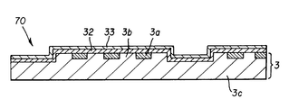
- FIG. 8 shows a cross sectional structure of the eighth embodiment.
- This master disk 70 consists of a conventional master disk 3 and a double-layered protective film formed on the surface of the conventional master disk 3 shown in FIG. 11 ( b ) or FIG. 12 ( d ).
- the first or lower protective film 32 is a carbon film of DLC.
- the usual methods for depositing the carbon film include the sputtering method and the ECR (Electron Cyclotron Resonance) plasma CVD method.
- the deposition in the sputtering method utilizes graphite as target material and Ar gas as sputtering gas. When the deposition is conducted adding hydrogen to the Ar gas, a hydrogen-added DLC film results, and when the deposition is conducted adding nitrogen to the Ar gas, a nitrogen-added DLC film results.
- the deposition in the ECR plasma CVD method is performed by decomposing gaseous hydrocarbon, such as methane, ethane or ethylene, in Ar plasma. When deposition by decomposition of hydrocarbon is conducted in plasma of mixed-gases of Ar and hydrogen, a hydrogen-added DLC film is obtained.
- a nitrogen-added DLC film is obtained. Thickness of the carbon film is determined from trade-off between magnetic contact duplication characteristics, principally intensity of transferring signal, of the embedded magnetic films 3 a to a magnetic recording disk on the one hand, and resistance to wear of the protective film on the other hand. In this aspect of embodiment, the thickness is favorably in the range of 50 to 1000 ⁇ . The optimum thickness has to be determined according to the magnetic properties, principally coercive force Hc, of the magnetic film of the magnetic recording disk. Pure DLC film has high electrical conductivity and effectively prevents adhering dust due to electrostatic force. A hydrogen-added DLC film provides a harder film than a pure DLC film. A nitrogen-added DLC film effectively prevents adhesion of corrosive gases, main component of which is sulfide.
- the second or upper protective film 33 is a lubricant film.
- the lubricant film brings about the following advantages. Firstly, friction between a magnetic recording disk and a master disk is substantially reduced. Secondly, when particles and chemical corrosive gases are accumulated on the surface of a master disk 70 after a large number, that is 10 to 100 thousand, of contact duplication operations, the particles and chemical corrosive gases can be removed by washing the lubricant with a solvent, to refresh the surface of the master disk.
- the lubricant and the solvent to be used in the lubricant film of the master disk may be the organic materials used in a lubricant film of a magnetic recording disk, for example,
- the average lifetime of a master disk comprising the carbon protective film 32 and a lubricant film 33 can be prolonged up to the order of several ten millions of contact duplication operations, in average.
- a master disk without a carbon protective film 32 after one hundred thousands of contact duplication operations the defects of cracks and peeling off were observed at the pattern edges of the embedded magnetic films, mainly at protrusions; the defects may be attributed to metal fatigue.
- such defects have been avoided up to several ten millions of operations in average in the master disk having a carbon protective film 32 according to this aspect of embodiment.
- the lubricant film 33 may be formed on the surface of the master disk 30 , 40 , 50 or 60 shown in FIGS. 4, 5 , 6 or 7 , instead of the conventional master disk 3 .
- FIG. 9 shows a magnetic contact duplication process or a preformatting process in a manufacturing method of a magnetic recording medium according to the invention.
- the magnetic recording disk 43 and the master disk 44 are joined together and immersed in a vessel filled with lubricating liquid for magnetic contact duplication.
- a permanent magnet is moved over the master disk 44 as illustrated in FIG. 11 ( b ).
- the article indicated by reference numeral 45 in FIG. 9 is a master disk holder.
- the lubricating liquid 41 may be isopropyl alcohol, the solvent C n F 2n+2 , where n is an integer of from 2 to 4, used in the eighth aspect of embodiment, or a solution of the lubricant HO—CH 2 —CF 2 —(CF 2 —O) m —(C 2 F 4 —O) n —CF 2 —CH 2 —OH, where each of m and n is an integer, and m+n is about 40, used in the eighth aspect of embodiment, dissolved in the solvent C n F 2n+2 , where n is an integer of from 2 to 4.
- the lubricating liquid 41 is replaced every ten thousands of operations and at that time, the master disk 44 is ultrasonically washed in the new lubricant.
- the disks may be exposed to vapor of the lubricating liquid.
- the vapor molecules also can exhibit lubricating capability.
- the present invention provides the following effects.
- a resin substrate allows the fabrication method in which discrete and isolated magnetic films are formed, and then, the step portion between the magnetic films are filled and made even with a resin surface portion of the resin substrate.
- the embedded magnetic films are surrounded by the resin surface portion, and the surfaces thereof can be made smooth and flat, suppressing protrusions and recesses in the boundary region. As a result, generation of flaws and gouges on the magnetic recording medium and to transfer of particles and chemical contaminants to the recording medium in the contact duplication process can be prevented.
- the resin surface portion having higher density than the other portion of the resin substrate enhances the anchoring effect of the resin surface portion with the embedded magnetic films to allow use of stronger magnet for duplication
- the density in the resin surface portion has a distribution in plane or lateral direction such that the density becomes higher as the position approaches nearer to the side-wall of the embedded magnetic film.
- the density in the resin surface portion has a distribution in depth or vertical direction such that the density becomes higher as the position approaches to the surface of the resin surface portion. The both density distributions provide stronger anchoring effect with the embedded magnetic films and enhanced durability of the master disk.
- the surface portion can be formed in the process wherein discrete and isolated magnetic films are first formed, then, fluid photo-setting resin is applied and made even, and then cured. Consequently, excellent surface flatness is achieved.
- a structure may be employed wherein a reinforcing substrate of silicon, for example, is laminated on the back surface of the resin substrate.
- the structure minimizes warping and distortion, and provides enhanced contact duplication accuracy and durability.
- thermo-setting resin may be employed for the material of the resin surface portion.
- the surfaces of the embedded magnetic films and the resin surface portion surrounding the magnetic films can be made smooth and flat, and protrusions and recesses at the boundary region are suppressed.
- the structure provided with a protective film covering the embedded magnetic films can reduce friction in a magnetic contact duplication process and prolongs life of contact duplication times.
- a double-layered protective film may be employed as a protective film.
- the lower protective film is a DLC film and the upper protective film is a lubricant film formed by coating lubricant on the lower protective film.
- the configuration provides remarkably prolonged life of contact duplication times.
- the DLC film is a hydrogen-added one, the film with higher hardness than a pure DLC film can be deposited.
- the DLC film is a nitrogen-added one, the film effectively prevent adsorption of corrosive gases, main component of which is sulfide.
- a method for manufacturing a master magnetic information carrier of the invention comprises the steps of forming discrete and isolated magnetic films in predetermined region by patterning a continuous magnetic film laminated on a surface of a resin base plate, and pressing the heated resin substrate from above the isolated magnetic film by a die.
- the resin surface portion is formed by a marking or stamping method, in which the surface region within the resin substrate itself is thermoplastically deformed. Therefore, the resin surface portion and the other portion of the resin substrate are in an integrated structure without any boundary in-between.
- the resin surface portion is denser than the other portion of the substrate because of the pressure molding adapted in the manufacturing method.
- the resin surface portion exhibits density distribution both in the plane or lateral direction and in the depth or vertical direction within the resin surface portion, which brings about a strong anchoring effect with the embedded magnetic films, eliminating risk of peeling off of the embedded magnetic films even when the magnetic force of the permanent magnet for magnetic contact duplication is strong.
- the manufacturing method of the invention may further comprise a step of coating the surface of the resin substrate with photo-setting resin film between the step of forming isolated magnetic film and the step of pressing the substrate with die, and also comprise a step of irradiating light from the back surface side of the resin substrate before releasing the die utilized in the pressing step.
- the resin surface portion with reduced strain and initial stress is obtained by the method.
- the recess portion of the die is adjusted to the position opposite the predetermined region for the magnetic films in the resin substrate and pushed down.
- the protrusion portion of the die first sink into the resin substrate, and then, the recess portion of the die catches the predetermined region within the recess portion of the die and presses the isolated magnetic film into the resin substrate. Consequently, the embedded magnetic films hardly drift relative to each other, and precise positioning of the embedded magnetic film is achieved.
- the portion formed by the protrusion of the die is useful as an air vent groove.
- Another method for manufacturing a master magnetic information carrier of the invention comprises steps of forming discrete and isolated magnetic films in a predetermined region by patterning a continuous magnetic film deposited on a surface of the refractory base plate, applying fluid thermosetting resin covering the isolated magnetic films on the refractory base plate, curing the fluid thermo-setting resin by heating, and etching-back a film of the cured thermo-setting resin until surfaces of the isolated magnetic films are exposed. Since the embedded magnetic films is exposed by etching-back, the surfaces of the embedded magnetic films and the resin surface portion of the substrate can be made smooth and flat, to obtain a master magnetic information carrier free from protrusion and recess at the boundary between the magnetic films and the resin surface portion.
- the invention further provides a method for manufacturing a magnetic recording medium including a preformatting step performing magnetic contact duplication from a master magnetic information carrier to a magnetic recording medium, wherein contact duplication is conducted with the master magnetic information carrier overlapped on the magnetic recording medium, and the two articles immersed in liquid of a lubricant or exposed to vapor of a lubricant. Since friction is reduced with the liquid or vapor of the lubricant, prolonged life of contact duplication times is achieved even in a master magnetic information carrier without a protective film.
Abstract
Description
Claims (18)
Applications Claiming Priority (2)
| Application Number | Priority Date | Filing Date | Title |
|---|---|---|---|
| JP11203697A JP2001034939A (en) | 1999-07-16 | 1999-07-16 | Master magnetic information carrier, production thereof and production of magnetic recording medium |
| JP11-203697 | 1999-07-16 |
Publications (1)
| Publication Number | Publication Date |
|---|---|
| US6613459B1 true US6613459B1 (en) | 2003-09-02 |
Family
ID=16478361
Family Applications (1)
| Application Number | Title | Priority Date | Filing Date |
|---|---|---|---|
| US09/617,357 Expired - Fee Related US6613459B1 (en) | 1999-07-16 | 2000-07-17 | Master magnetic information carrier, fabrication method thereof, and a method for manufacturing a magnetic recording medium |
Country Status (2)
| Country | Link |
|---|---|
| US (1) | US6613459B1 (en) |
| JP (1) | JP2001034939A (en) |
Cited By (21)
| Publication number | Priority date | Publication date | Assignee | Title |
|---|---|---|---|---|
| US20020187368A1 (en) * | 2001-05-14 | 2002-12-12 | Yuuji Senzaki | Magnetic recording medium and a method of manufacture thereof |
| US20030152808A1 (en) * | 2001-12-14 | 2003-08-14 | Fuji Photo Film Co., Ltd. | Flexible magnetic recording medium |
| US20040160691A1 (en) * | 2003-02-18 | 2004-08-19 | Fuji Photo Film Co., Ltd. | Master information carrier for magnetic transfer |
| US20040161576A1 (en) * | 2003-02-14 | 2004-08-19 | Hiroyuki Yoshimura | Method of manufacturing master disc for magnetic transfer, a master disc thereof, and a master disc formed thereby |
| US20050185311A1 (en) * | 2003-04-01 | 2005-08-25 | Fujitsu Limited | Magnetic pattern transfer method |
| US20050242453A1 (en) * | 2001-07-12 | 2005-11-03 | Fuji Photo Film Co., Ltd. | Master carrier for magnetic transfer |
| US20060165959A1 (en) * | 2005-01-26 | 2006-07-27 | Bandic Zvonimir Z | Contact magnetic transfer template |
| US20070147348A1 (en) * | 2005-12-23 | 2007-06-28 | Tingting Lu | Methods, systems, and computer program products for providing location information for VoIP emergency calling |
| US20080117544A1 (en) * | 2006-11-21 | 2008-05-22 | Kabushiki Kaisha Toshiba | Magnetic recording medium, method for manufacturing the same, and magnetic recording apparatus |
| US20080241595A1 (en) * | 2007-03-26 | 2008-10-02 | Kabushiki Kaisha Toshiba | Magnetic recording medium |
| US20090081482A1 (en) * | 2007-09-26 | 2009-03-26 | Kabushiki Kaisha Toshiba | Magnetic recording medium and method of manufacturing the same |
| US20090162704A1 (en) * | 2007-06-29 | 2009-06-25 | Kabushiki Kaisha Toshiba | Method of manufacturing magnetic recording medium and magnetic recording medium |
| US20090179138A1 (en) * | 2008-01-16 | 2009-07-16 | Visera Technologies Company Limited | Soft mold and fabrication method thereof |
| US20100086808A1 (en) * | 2008-08-27 | 2010-04-08 | Fuji Electric Device Technology Co., Ltd. | Method of forming a protective film for a magnetic recording medium, a protective film formed by the method and a magnetic recording medium having the protective film |
| US7719793B2 (en) | 2005-12-28 | 2010-05-18 | Hitachi Global Storage Technologies Netherlands B.V. | Circumferentially patterned disk for longitudinal and perpendicular recording |
| US20100167090A1 (en) * | 2008-12-22 | 2010-07-01 | Fuji Electric Device Technology Co. Ltd. | Method of forming a protective film, a protective film obtained by the method, and a magnetic recording medium including the protective film |
| US20130070370A1 (en) * | 2010-09-30 | 2013-03-21 | Seagate Technology Llc | Planarization Method for Media |
| US20180286582A1 (en) * | 2017-03-31 | 2018-10-04 | International Business Machines Corporation | Magnetic inductor with shape anisotrophy |
| US10593449B2 (en) | 2017-03-30 | 2020-03-17 | International Business Machines Corporation | Magnetic inductor with multiple magnetic layer thicknesses |
| US10597769B2 (en) | 2017-04-05 | 2020-03-24 | International Business Machines Corporation | Method of fabricating a magnetic stack arrangement of a laminated magnetic inductor |
| US11170933B2 (en) | 2017-05-19 | 2021-11-09 | International Business Machines Corporation | Stress management scheme for fabricating thick magnetic films of an inductor yoke arrangement |
Families Citing this family (1)
| Publication number | Priority date | Publication date | Assignee | Title |
|---|---|---|---|---|
| JP2004213700A (en) | 2002-11-15 | 2004-07-29 | Fuji Electric Device Technology Co Ltd | Master disk for magnetic recording medium, and positioning device and method |
Citations (9)
| Publication number | Priority date | Publication date | Assignee | Title |
|---|---|---|---|---|
| US4363844A (en) * | 1980-09-22 | 1982-12-14 | Lewis Terry W | Metallized information carrying discs |
| US5637373A (en) * | 1992-11-19 | 1997-06-10 | Semiconductor Energy Laboratory Co., Ltd. | Magnetic recording medium |
| US5677051A (en) * | 1993-11-30 | 1997-10-14 | Tdk Corporation | Magnetic recording medium having a specified plasma polymerized hydrogen containing carbon film and lubricant |
| US5703733A (en) * | 1995-03-06 | 1997-12-30 | Mitsubishi Denki Kabushiki Kaisha | Magetic recording/reproducing method, magnetic reproducing apparatus used therefor, magnetic recording medium and method for producing the same |
| WO1998003972A1 (en) * | 1996-07-22 | 1998-01-29 | Matsushita Electric Industrial Co., Ltd. | Master information carrier, process for producing the carrier, and method and apparatus for recording master information signal on magnetic recording medium by using the carrier |
| JPH1040544A (en) | 1996-07-22 | 1998-02-13 | Matsushita Electric Ind Co Ltd | Master information carrier and method for recording master information signal on magnetic recording medium |
| US5768075A (en) * | 1991-12-17 | 1998-06-16 | Baradun R&D Ltd. | Disk medium w/magnetically filled features aligned in rows and columns |
| JPH1125455A (en) | 1997-06-30 | 1999-01-29 | Matsushita Electric Ind Co Ltd | Magnetic transfer device |
| US6433944B1 (en) * | 1998-09-25 | 2002-08-13 | Fuji Photo Film Co., Ltd. | Master carrier for magnetic transfer and method for transfer |
-
1999
- 1999-07-16 JP JP11203697A patent/JP2001034939A/en not_active Withdrawn
-
2000
- 2000-07-17 US US09/617,357 patent/US6613459B1/en not_active Expired - Fee Related
Patent Citations (10)
| Publication number | Priority date | Publication date | Assignee | Title |
|---|---|---|---|---|
| US4363844A (en) * | 1980-09-22 | 1982-12-14 | Lewis Terry W | Metallized information carrying discs |
| US5768075A (en) * | 1991-12-17 | 1998-06-16 | Baradun R&D Ltd. | Disk medium w/magnetically filled features aligned in rows and columns |
| US5637373A (en) * | 1992-11-19 | 1997-06-10 | Semiconductor Energy Laboratory Co., Ltd. | Magnetic recording medium |
| US5677051A (en) * | 1993-11-30 | 1997-10-14 | Tdk Corporation | Magnetic recording medium having a specified plasma polymerized hydrogen containing carbon film and lubricant |
| US5703733A (en) * | 1995-03-06 | 1997-12-30 | Mitsubishi Denki Kabushiki Kaisha | Magetic recording/reproducing method, magnetic reproducing apparatus used therefor, magnetic recording medium and method for producing the same |
| WO1998003972A1 (en) * | 1996-07-22 | 1998-01-29 | Matsushita Electric Industrial Co., Ltd. | Master information carrier, process for producing the carrier, and method and apparatus for recording master information signal on magnetic recording medium by using the carrier |
| JPH1040544A (en) | 1996-07-22 | 1998-02-13 | Matsushita Electric Ind Co Ltd | Master information carrier and method for recording master information signal on magnetic recording medium |
| US6347016B1 (en) * | 1996-07-22 | 2002-02-12 | Matsushita Electric Industrial Co., Ltd. | Master information carrier, process for producing the carrier, and method and apparatus for recording master information signal on magnetic recording medium by using the carrier |
| JPH1125455A (en) | 1997-06-30 | 1999-01-29 | Matsushita Electric Ind Co Ltd | Magnetic transfer device |
| US6433944B1 (en) * | 1998-09-25 | 2002-08-13 | Fuji Photo Film Co., Ltd. | Master carrier for magnetic transfer and method for transfer |
Cited By (41)
| Publication number | Priority date | Publication date | Assignee | Title |
|---|---|---|---|---|
| US20020187368A1 (en) * | 2001-05-14 | 2002-12-12 | Yuuji Senzaki | Magnetic recording medium and a method of manufacture thereof |
| US20050242453A1 (en) * | 2001-07-12 | 2005-11-03 | Fuji Photo Film Co., Ltd. | Master carrier for magnetic transfer |
| US20030152808A1 (en) * | 2001-12-14 | 2003-08-14 | Fuji Photo Film Co., Ltd. | Flexible magnetic recording medium |
| US6824835B2 (en) * | 2001-12-14 | 2004-11-30 | Fuji Photo Film Co., Ltd. | Flexible magnetic recording medium |
| US20040161576A1 (en) * | 2003-02-14 | 2004-08-19 | Hiroyuki Yoshimura | Method of manufacturing master disc for magnetic transfer, a master disc thereof, and a master disc formed thereby |
| US20040160691A1 (en) * | 2003-02-18 | 2004-08-19 | Fuji Photo Film Co., Ltd. | Master information carrier for magnetic transfer |
| US20050185311A1 (en) * | 2003-04-01 | 2005-08-25 | Fujitsu Limited | Magnetic pattern transfer method |
| US7362524B2 (en) * | 2003-04-01 | 2008-04-22 | Fujitsu Limited | Magnetic pattern transfer method |
| US20060165959A1 (en) * | 2005-01-26 | 2006-07-27 | Bandic Zvonimir Z | Contact magnetic transfer template |
| US7572499B2 (en) * | 2005-01-26 | 2009-08-11 | Hitachi Global Storage Technologies Netherlands B.V. | Contact magnetic transfer template |
| US20070147348A1 (en) * | 2005-12-23 | 2007-06-28 | Tingting Lu | Methods, systems, and computer program products for providing location information for VoIP emergency calling |
| US20100181286A1 (en) * | 2005-12-28 | 2010-07-22 | Vladimir Nikitin | Method for manufacturing a circumferentially patterned disk for longitudinal and perpendicular recording |
| US7719793B2 (en) | 2005-12-28 | 2010-05-18 | Hitachi Global Storage Technologies Netherlands B.V. | Circumferentially patterned disk for longitudinal and perpendicular recording |
| US8318331B2 (en) * | 2006-11-21 | 2012-11-27 | Kabushiki Kaisha Toshiba | Magnetic recording medium, method for manufacturing the same, and magnetic recording apparatus |
| US20080117544A1 (en) * | 2006-11-21 | 2008-05-22 | Kabushiki Kaisha Toshiba | Magnetic recording medium, method for manufacturing the same, and magnetic recording apparatus |
| US20080241595A1 (en) * | 2007-03-26 | 2008-10-02 | Kabushiki Kaisha Toshiba | Magnetic recording medium |
| US8043516B2 (en) | 2007-06-29 | 2011-10-25 | Kabushiki Kaisha Toshiba | Method of manufacturing magnetic recording medium and magnetic recording medium |
| US20090162704A1 (en) * | 2007-06-29 | 2009-06-25 | Kabushiki Kaisha Toshiba | Method of manufacturing magnetic recording medium and magnetic recording medium |
| US8475949B2 (en) | 2007-06-29 | 2013-07-02 | Kabusihki Kaisha Toshiba | Method for manufacturing magnetic recording medium and magnetic recording medium |
| US20090081482A1 (en) * | 2007-09-26 | 2009-03-26 | Kabushiki Kaisha Toshiba | Magnetic recording medium and method of manufacturing the same |
| US8338007B2 (en) | 2007-09-26 | 2012-12-25 | Kabushiki Kaisha Toshiba | Magnetic recording medium and magnetic recording apparatus |
| US8652338B2 (en) | 2007-09-26 | 2014-02-18 | Kabushiki Kaisha Toshiba | Magnetic recording medium and method of manufacturing the same |
| TWI424468B (en) * | 2008-01-16 | 2014-01-21 | Visera Technologies Co Ltd | Soft mold and fabrication method thereof |
| US20090179138A1 (en) * | 2008-01-16 | 2009-07-16 | Visera Technologies Company Limited | Soft mold and fabrication method thereof |
| US8865269B2 (en) | 2008-08-27 | 2014-10-21 | Fuji Electric Co., Ltd. | Method of forming a protective film for a magnetic recording medium, a protective film formed by the method and a magnetic recording medium having the protective film |
| US8182883B2 (en) * | 2008-08-27 | 2012-05-22 | Fuji Electric Co., Ltd. | Method of forming a protective film for a magnetic recording medium, a protective film formed by the method and a magnetic recording medium having the protective film |
| US20100086808A1 (en) * | 2008-08-27 | 2010-04-08 | Fuji Electric Device Technology Co., Ltd. | Method of forming a protective film for a magnetic recording medium, a protective film formed by the method and a magnetic recording medium having the protective film |
| US8334028B2 (en) | 2008-12-22 | 2012-12-18 | Fuji Electric Co., Ltd. | Method of forming a protective film |
| US20100167090A1 (en) * | 2008-12-22 | 2010-07-01 | Fuji Electric Device Technology Co. Ltd. | Method of forming a protective film, a protective film obtained by the method, and a magnetic recording medium including the protective film |
| US20130070370A1 (en) * | 2010-09-30 | 2013-03-21 | Seagate Technology Llc | Planarization Method for Media |
| US8946835B2 (en) * | 2010-09-30 | 2015-02-03 | Seagate Technology Llc | Magnetic device with different planarization areas |
| US11361889B2 (en) | 2017-03-30 | 2022-06-14 | International Business Machines Corporation | Magnetic inductor with multiple magnetic layer thicknesses |
| US10593449B2 (en) | 2017-03-30 | 2020-03-17 | International Business Machines Corporation | Magnetic inductor with multiple magnetic layer thicknesses |
| US10593450B2 (en) | 2017-03-30 | 2020-03-17 | International Business Machines Corporation | Magnetic inductor with multiple magnetic layer thicknesses |
| US11222742B2 (en) | 2017-03-31 | 2022-01-11 | International Business Machines Corporation | Magnetic inductor with shape anisotrophy |
| US10607759B2 (en) * | 2017-03-31 | 2020-03-31 | International Business Machines Corporation | Method of fabricating a laminated stack of magnetic inductor |
| US20180286582A1 (en) * | 2017-03-31 | 2018-10-04 | International Business Machines Corporation | Magnetic inductor with shape anisotrophy |
| US10597769B2 (en) | 2017-04-05 | 2020-03-24 | International Business Machines Corporation | Method of fabricating a magnetic stack arrangement of a laminated magnetic inductor |
| US11479845B2 (en) | 2017-04-05 | 2022-10-25 | International Business Machines Corporation | Laminated magnetic inductor stack with high frequency peak quality factor |
| US11170933B2 (en) | 2017-05-19 | 2021-11-09 | International Business Machines Corporation | Stress management scheme for fabricating thick magnetic films of an inductor yoke arrangement |
| US11367569B2 (en) | 2017-05-19 | 2022-06-21 | International Business Machines Corporation | Stress management for thick magnetic film inductors |
Also Published As
| Publication number | Publication date |
|---|---|
| JP2001034939A (en) | 2001-02-09 |
Similar Documents
| Publication | Publication Date | Title |
|---|---|---|
| US6613459B1 (en) | Master magnetic information carrier, fabrication method thereof, and a method for manufacturing a magnetic recording medium | |
| JP2004178794A (en) | Vertical magnetic discrete track recording disk | |
| US20060275692A1 (en) | Method for forming concavo-convex pattern, method for manufacturing master disk, method for manufacturing stamper, and method for manufacturing magnetic recording medium | |
| JP4008933B2 (en) | Magnetic recording medium, method for manufacturing the same, and magnetic recording apparatus | |
| JP5053007B2 (en) | Imprint mold structure, imprint method using the imprint mold structure, and magnetic recording medium | |
| US20060269791A1 (en) | Magnetic recording medium, magnetic recording and reproducing apparatus, stamper, method of manufacturing stamper, and method of manufacturing magnetic recording medium | |
| JP2006346820A (en) | Nano-hole structure and its manufacturing method, stamper and its manufacturing method, magnetic recording medium and its manufacturing method, and magnetic recording device and magnetic recording method | |
| KR20020086291A (en) | Master carrier for magnetic transfer | |
| US6858328B1 (en) | Master information support | |
| US20080203053A1 (en) | Method for manufacturing magnetic recording medium, stamper, transferring apparatus, and method for forming resin mask | |
| JP4977121B2 (en) | Imprint mold structure, imprint method using the same, and method for manufacturing magnetic recording medium | |
| JP5033003B2 (en) | Mold structure, imprint method using the same, magnetic recording medium and method for manufacturing the same | |
| US6950252B2 (en) | Master carrier for magnetic transfer | |
| JP2008276907A (en) | Mold structure, imprinting method using the same, magnetic recording medium and production method thereof | |
| JP2009208447A (en) | Mold structure for imprint, imprint method, magnetic recording medium and method for manufacturing the same | |
| JP2009245555A (en) | Production method of magnetic transfer master carrier, magnetic transfer master carrier, magnetic transfer method, and magnetic recording medium | |
| JP2008276906A (en) | Mold structure, imprinting method using the same, magnetic recording medium and production method thereof | |
| JP4662594B2 (en) | Method for removing foreign matter from master magnetic information carrier | |
| JP2007310943A (en) | Magnetic transfer master carrier, magnetic transfer method, magnetic recording medium thereby manufactured, and magnetic recording/reproducing device | |
| JP4089904B2 (en) | Method for manufacturing magnetic recording medium | |
| JP5829671B2 (en) | Method for producing a master recording medium | |
| JP2009004066A (en) | Mold structure and imprint method using the same, and magnetic recording medium and its manufacturing method | |
| JP2007059006A (en) | Method for manufacturing original disk, method for manufacturing stamper and method for manufacturing magnetic recording medium | |
| JP2009048752A (en) | Imprint mold structure, and imprinting method using the same, magnetic recording medium, and method for manufacturing magnetic recording medium | |
| JP2002373417A (en) | Magnetic recording medium |
Legal Events
| Date | Code | Title | Description |
|---|---|---|---|
| AS | Assignment |
Owner name: FUJI ELECTRIC CO., LTD., JAPAN Free format text: ASSIGNMENT OF ASSIGNORS INTEREST;ASSIGNORS:SAITO, AKIRA;NIMURA, KAZUO;OTSUKI, AKIHIRO;REEL/FRAME:011098/0377 Effective date: 20000731 |
|
| FEPP | Fee payment procedure |
Free format text: PAYOR NUMBER ASSIGNED (ORIGINAL EVENT CODE: ASPN); ENTITY STATUS OF PATENT OWNER: LARGE ENTITY |
|
| FPAY | Fee payment |
Year of fee payment: 4 |
|
| AS | Assignment |
Owner name: FUJI ELECTRIC HOLDINGS CO., LTD., JAPAN Free format text: CHANGE OF NAME;ASSIGNOR:FUJI ELECTRIC CO., LTD.;REEL/FRAME:021050/0015 Effective date: 20031001 Owner name: FUJI ELECTRIC DEVICE TECHNOLOGY CO., LTD., JAPAN Free format text: ASSIGNMENT OF ASSIGNORS INTEREST;ASSIGNOR:FUJI ELECTRIC HOLDINGS CO., LTD.;REEL/FRAME:021050/0023 Effective date: 20080526 |
|
| REMI | Maintenance fee reminder mailed | ||
| LAPS | Lapse for failure to pay maintenance fees | ||
| STCH | Information on status: patent discontinuation |
Free format text: PATENT EXPIRED DUE TO NONPAYMENT OF MAINTENANCE FEES UNDER 37 CFR 1.362 |
|
| FP | Lapsed due to failure to pay maintenance fee |
Effective date: 20110902 |