US6597999B1 - Method and system for real-time prediction of zero crossings of fault currents - Google Patents

Method and system for real-time prediction of zero crossings of fault currents Download PDF

Info

Publication number
US6597999B1
US6597999B1 US09/467,139 US46713999A US6597999B1 US 6597999 B1 US6597999 B1 US 6597999B1 US 46713999 A US46713999 A US 46713999A US 6597999 B1 US6597999 B1 US 6597999B1
Authority
US
United States
Prior art keywords
fault current
zero crossing
fault
post
zero
Prior art date
Legal status (The legal status is an assumption and is not a legal conclusion. Google has not performed a legal analysis and makes no representation as to the accuracy of the status listed.)
Expired - Lifetime
Application number
US09/467,139
Inventor
Gautam Sinha
William James Premerlani
Vlatko Vlatkovic
Current Assignee (The listed assignees may be inaccurate. Google has not performed a legal analysis and makes no representation or warranty as to the accuracy of the list.)
General Electric Co
Original Assignee
General Electric Co
Priority date (The priority date is an assumption and is not a legal conclusion. Google has not performed a legal analysis and makes no representation as to the accuracy of the date listed.)
Filing date
Publication date
Application filed by General Electric Co filed Critical General Electric Co
Priority to US09/467,139 priority Critical patent/US6597999B1/en
Assigned to GENERAL ELECTRIC COMPANY reassignment GENERAL ELECTRIC COMPANY ASSIGNMENT OF ASSIGNORS INTEREST (SEE DOCUMENT FOR DETAILS). Assignors: VLATKOVIC, VLATKO (NMN), PREMERLANI, WILLIAM JAMES, SINHA, GAUTAM (NMN)
Application granted granted Critical
Publication of US6597999B1 publication Critical patent/US6597999B1/en
Anticipated expiration legal-status Critical
Expired - Lifetime legal-status Critical Current

Links

Images

Classifications

    • HELECTRICITY
    • H01ELECTRIC ELEMENTS
    • H01HELECTRIC SWITCHES; RELAYS; SELECTORS; EMERGENCY PROTECTIVE DEVICES
    • H01H9/00Details of switching devices, not covered by groups H01H1/00 - H01H7/00
    • H01H9/54Circuit arrangements not adapted to a particular application of the switching device and for which no provision exists elsewhere
    • H01H9/56Circuit arrangements not adapted to a particular application of the switching device and for which no provision exists elsewhere for ensuring operation of the switch at a predetermined point in the ac cycle
    • HELECTRICITY
    • H01ELECTRIC ELEMENTS
    • H01HELECTRIC SWITCHES; RELAYS; SELECTORS; EMERGENCY PROTECTIVE DEVICES
    • H01H33/00High-tension or heavy-current switches with arc-extinguishing or arc-preventing means
    • H01H33/006High-tension or heavy-current switches with arc-extinguishing or arc-preventing means adapted for interrupting fault currents with delayed zero crossings

Definitions

  • the invention relates generally to point on wave switching and more particularly to real-time prediction of zero crossings of fault currents for use in point on wave switching.
  • a method for predicting zero crossings of fault currents in multi-phase power systems includes sensing a fault current in each respective phase, estimating parameters of a model of each respective fault current, and independently using the estimated parameters for each respective fault current to predict a zero crossing (here and hereinafter meaning at least one zero crossing) of the respective fault current.
  • a method for predicting zero crossings of a fault current in a power system includes sensing the fault current; estimating parameters of a model of the fault current; and using the estimated parameters to predict a zero crossing of the fault current by (a) selecting an initial time interval in which a zero crossing is present, (b) identifying a portion of the interval that includes the zero crossing, (c) changing the interval to comprise the identified portion, and (d) determining whether the changed interval provides a desired resolution, and, if not, cycling through elements (b)-(d) until the changed interval provides the desired resolution.
  • a method for predicting zero crossings of a fault current in a power system includes sensing the fault current; estimating parameters of a model of the fault current; and using the estimated parameters to predict a zero crossing of the fault current by (a) predicting a predicted post-fault current zero crossing, (b) determining an actual post-fault current zero crossing, (c) determining a difference between the predicted and actual post fault current zero crossing, and (d) using the difference to predict an additional post-fault current zero crossing, the additional crossing occurring subsequent to the predicted crossing.
  • FIG. 1 illustrates a conventional control system for switching devices.
  • FIG. 2 is a flowchart of process steps for execution in a controller in accordance with one embodiment of the present invention.
  • FIG. 3 is a flow chart of process steps for execution in the controller in conjunction with the process steps of FIG. 2 in accordance with a first more specific embodiment of the present invention.
  • FIG. 4 is a time line for further illustrating the embodiment of FIG. 3 .
  • FIG. 5 is a flow chart of process steps for execution in the controller in conjunction with the process steps of FIG. 2 in accordance with a second more specific embodiment of the present invention.
  • FIGS. 6 and 7 are graphs of simulation results of the embodiment of FIG. 5 .
  • FIG. 1 illustrates a conventional control system for switching devices as described in aforementioned Long et al., U.S. Pat. No. 4,922,363.
  • Three phase alternating current is supplied via lines 10 , 12 , and 14 to a switching device 16 having three sets of contact tips 18 , 20 and 22 . Closure of the tips can effected by an actuator 34 .
  • the tips 18 , 20 and 22 are closed, current is supplied along the lines marked phase A, phase B and phase C to a load shown as an AC motor 28 .
  • Line fuses 42 are coupled between the switching device and the load.
  • Switching device 16 may comprise a circuit breaker, circuit switch, load break switch, or re-closer, for example.
  • Actuator 24 is powered and controlled by switching device controller 26 .
  • Controller 26 monitors the currents in lines phase A, phase B and phase C by means of corresponding sensors 30 , 32 and 34 which in one embodiment may comprise current transformers, for example.
  • the connecting links from the sensors may include other protective relays or overcurrent devices indicated at 36 , 38 , and 40 .
  • Controller 26 is a microprocessor based control and typically includes volatile memory (RAM), non-volatile memory (ROM), a central processing unit (CPU), analog to digital (A/D) converters and various interface adapter circuits. After the controller 26 receives a stop command, controller 26 selectively controls openings of contactor tips 18 , 20 , and 22 .
  • FIG. 2 is a flowchart of process steps for execution in a controller in accordance with one embodiment of the present invention.
  • the present invention is described, for purposes of example, with a three phase power system, aspects of the present invention can be additionally used on single or other multi-phase power systems.
  • Each of the zero-crossing prediction embodiments include the following: (a) sensing of a fault event in an application; (b) sensing the fault current in each phase; (c) estimating parameters of a model of each fault current; and (d) using the estimated parameters to predict a zero crossing of the fault current for each phase independently of the other phase calculations.
  • the presence of a fault is detected.
  • the presence is detected by comparing the magnitude of each phase current with a respective predetermined range and identifying a fault if any of the phase currents falls outside of the predetermined range.
  • a threshold level ranging from about 5 ⁇ to about 10 ⁇ amps, for example, is the threshold above which a fault is declared.
  • step 46 fault currents are sensed for each phase.
  • Analog fault currents are sensed and converted to digital signals at a sufficiently high sampling frequency.
  • the sampling frequency will be a power of 2 times the frequency of the sinusoid.
  • a 60 Hz sinusoid may have frequencies of 32 ⁇ 60 Hz (1920 Hz) or 64 ⁇ 60 (3840 Hz) or 128 ⁇ 60 Hz (7680 Hz).
  • step 48 for each phase, the parameters of a model of the fault current are estimated.
  • the following equation is a transcendental equation model of sampled fault current I(t) as a 50 or 60 Hz sinusoid with unknown phase angle and amplitude and with a decaying DC offset term:
  • I ( t ) Ae ( ⁇ t/ ⁇ ) +B cos( ⁇ t )+C sin( ⁇ t ) (1)
  • A represents the exponential component
  • B and C represent sinusoidal components
  • represents the utility grid angular frequency (377 radians/sec in North America and most of Europe, 314.2 radians/sec in England and Japan, for example)
  • represents a DC offset decay time constant.
  • the DC offset decay time constant is first estimated. According to one embodiment of the present invention, the estimation is performed by the following equations:
  • FFT represents a fast fourier transform
  • j represents a current time index
  • L represents the number of sample points (either of the of the FFT of equation 3a or of the window of equation 4)
  • i phase represents the phase current for one phase
  • m represents the harmonic order of the estimate
  • DC(j) represents a direct current average value (that is, for example, in equation 3b a direct current value of the FFA and in equation 4 an average of the last L samples of the phase current)
  • p represents an index
  • T S represents the sampling period
  • ln represents the natural logarithm.
  • a ⁇ ⁇ ( j ) DC ⁇ ( j ) ⁇ ⁇ ( j - L - 1 ) ⁇ T s ⁇ ⁇ ⁇ ( j ) . (6a)
  • the initial fault current magnitude is estimated using recursion:
  • a ⁇ ⁇ ( j ) A ⁇ ⁇ ( j - 1 ) * ⁇ ⁇ ⁇ ⁇ ( j ) ⁇ ⁇ ⁇ ( j - 1 ) * DC ⁇ ( j ) DC ⁇ ( j - 1 ) ⁇ ⁇ T s ⁇ ⁇ ⁇ ( j ) * ( ⁇ - ( L - 1 ) * T s ⁇ ⁇ ⁇ ( j ) - 1 ) / ( ⁇ - ( L - 1 ) * T s ⁇ ⁇ ⁇ ( j - 1 ) - 1 ) .
  • phase angle ⁇ is estimated and used to estimate the sinusoidal components B and C.
  • the estimation is performed by using the first two terms of a fast fourier transform (FFT) of the measured fault current and subtracting the estimated DC offset current.
  • FFT fast fourier transform
  • i represents an index value
  • Controller 26 of FIG. 1 may comprise a digital signal processor or other type of computer, for example, and may be included in controls of an associated switching device or in a separate unit. Switching device applications will benefit from the robust implementation, and the feedback of the prediction technique will provide improved immunity to noise. Also, errors due to the presence of current harmonics and other non-idealities such as numerical sensitivity, and sampling process aliasing and quantization can be reduced by using one of the closed loop techniques that are described below.
  • convergence to a solution of equation 1 can be a time-consuming process.
  • solving equation 1 provides multiple solutions due to the sine and cosine terms.
  • zero crossing predictions are achieved without directly solving the transcendental equation modeling the fault current.
  • FIG. 3 is a flow chart of process steps for execution in the controller in conjunction with the process steps of FIG. 2 in accordance with a first more specific embodiment of the present invention
  • FIG. 4 is a time line for further illustrating the embodiment of FIG. 3 .
  • This embodiment of the invention includes an efficient method for indirectly solving, in real-time, a transcendental equation that models the behavior of a fault current and improves the reliability of switching devices such as circuit breakers by reducing arcing and has the advantage that the only sensors required are current sensors that are typically already present.
  • zero crossings for each phase are each predicted using the estimated parameters for each respective fault current by selecting an initial time interval in which a zero crossing is present (step 52 ), identifying a portion of the interval that includes the zero crossing (step 54 ), changing the interval to comprise the identified portion (step 56 ), and determining whether the changed interval provides a desired resolution (step 58 ). If the changed interval does not, the identifying, changing, and determining are sequentially performed until the changed interval provides the desired resolution.
  • the sign of current I(t) is evaluated at two time points t 1 and t 2 (interval (t 1 , t 2 )).
  • the bisection method is applicable because the fault currents change polarity at each zero crossing.
  • the identified time points and interval between them has the property that I(t 1 )*I(t 2 ) ⁇ 0.
  • t 3 is the mid-point of the original interval.
  • t 3 can be situated anywhere within the interval, and, if desired, multiple time points between t 1 and t 2 can be used when identifying the portion of the interval with the zero crossing.
  • the product of the signs of I(t 3 ) and I(t 2 ) is used to determine whether the interval of interest becomes (t 3 ,t 2 ) or (t 1 ,t 3 ). If I(t 3 )*I(t 2 ) is less than zero, then the interval of interest becomes (t 3 ,t 2 ). Otherwise, the interval of interest becomes (t 1 ,t 3 ).
  • the product of I(t 3 ) and I(t 1 ) can be used to select the interval of interest by determining that if I(t 3 )*I(t 1 ) is less than zero, then the interval of interest becomes (t 1 ,t 3 ), else the interval of interest becomes (t 3 ,t 2 ).
  • T w will typically be less than or equal to about 100 microseconds.
  • t 4 can be calculated to be the time instant half way between the selected t 1 and t 3 or t 3 and t 2 points and the currents can be calculated and multiplied to determine the next interval in the same manner as discussed above. In the example of FIG. 4, the crossing lies between t 4 and t 6 .
  • the selection of the initial two time points t 1 and t 2 will depend on the estimations of parameters ⁇ , A, B, and C and will be unique to each zero crossing.
  • the t 1 and t 2 time points associated with the first zero crossing of interest are estimated by first rewriting
  • the DC offset is in the range of about 10 percent to about 15 percent.
  • the zero of equation 1 will fall near to the zero of equation 14. That is, near to:
  • n 0(for first post-fault crossing), 1, 3, 5, 7, 9, 11, 13 . . .
  • t 1 and t 2 can be estimated as:
  • is a number which is adjusted according to the uncertainty of the ⁇ estimate. Higher uncertainties lead to higher ⁇ s.
  • the initial interval for the second zero crossing can be calculated using equation 17 as follows:
  • the initial interval for the third zero crossing can be calculated using equation 17 as follows:
  • the value of ⁇ can either remain constant (for an open loop embodiment) or change with later crossings (for a closed loop embodiment).
  • the advantage to reducing ⁇ depends on the number of iterations used to get to the solution for the earlier zero crossing.
  • the number of iterations can be reduced. Intervals of subsequent zero crossings can benefit from earlier data rather than using the above equations that are based on ⁇ and ⁇ . For example, these intervals can start out in the area of a second or later iteration.
  • the number of iterations N required to produce a prediction of a zero crossing within window T w is given by:
  • N ln 2 (( t 2 ⁇ t 1 )/ T w ).
  • ln 2 represents a logarithm to base 2.
  • the zero crossing will occur in the identified interval and be within the window T w .
  • the zero crossing could arbitrarily be declared as occurring at the midpoint of the final identified interval.
  • Estimates of the parameters can change over time. For improved accuracy, the parameters and ⁇ can be recalculated. If the parameters A, ⁇ , B, and C are continuously recalculated, equation 16 can be recalculated to improve the accuracy of the ⁇ calculation and the accuracy of the zero crossing prediction.
  • a correction factor can be used to improve the selection of initial intervals for subsequent zero crossing determinations.
  • the actual zero crossing (t T ) is measured by the current sensors and used with its respective interval for improving the selection of a subsequent interval.
  • Equations 26a and 26b can be used for setting the initial interval for the second zero crossing. Equations 26a and 26b are useful if the actual zero crossing is within the initial interval. If the actual zero crossing was not within the initial interval, then the size of subsequent initial intervals is increased to a sufficient degree such that the actual zero crossings lie within them.
  • FIG. 5 is a flow chart of process steps for execution in the controller in conjunction with the process steps of FIG. 2 in accordance with a second more specific embodiment of the present invention
  • FIGS. 6 and 7 are graphs of simulation results of the embodiment of FIG. 5 .
  • the estimated parameters for each respective fault current is used to predict the zero crossing of the respective fault current by predicting a predicted post-fault current zero crossing (step 62 ), determining an actual post-fault current zero crossing (step 64 ), determining a difference between the predicted and actual post fault current zero crossing, and using the difference to predict an additional post-fault current zero crossing, the additional crossing occurring subsequent to the predicted crossing. More particularly, using the difference in one embodiment comprises using the difference to estimate a correction factor (step 66 ) and then using the correction factor to predict the additional crossing (step 68 ).
  • a preliminary prediction t zero,n of the n th post-fault current zero crossing can be calculated as:
  • a range of about three to about five cycles (windows) of operation is the regime of interest with each cycle including two zero crossings.
  • the time error between the predicted and the actual k th zero crossing is measured. Based on this error, a correction term is added to modify the predicted n th zero crossing as
  • FIGS. 6-7 Simulation results are shown in FIGS. 6-7 with FIG. 6 representing an embodiment with a signal-to-noise ratio of 240 decibels and FIG. 7 representing an embodiment with a signal-to-noise ratio of 60 decibels.
  • FIG. 6 each of the zero crossings after the first post-fault zero crossing was predicted at a value within 0.2 milliseconds of the true zero crossing.
  • FIG. 7 each of the zero crossings after the first post-fault zero crossing was predicted at a value within 0.4 milliseconds of the true zero crossing.

Abstract

A method for predicting zero crossings of fault currents in a multi-phase power system includes sensing a fault current in each respective phase, estimating parameters of a model of each respective fault current, and independently using the estimated parameters for each respective fault current to predict a zero crossing of the respective fault current.

Description

BACKGROUND
The invention relates generally to point on wave switching and more particularly to real-time prediction of zero crossings of fault currents for use in point on wave switching.
As described in commonly assigned Long et al., U.S. Pat. No. 4,922,363, to apply electromechanical contactors for switching currents in power systems that have available fault currents greater than the interrupting capacity of a contactor, it is necessary to protect the contactor from damage by backing it up with a series device that is sufficiently fast acting to interrupt fault currents prior to the contactor opening at all values of current above the interrupting capacity of the contactor. In control gear, back up fuses are used to provide this function. These fuses must also be capable of interrupting the maximum prospective fault current that can flow during a short circuit. In order to maintain good contactor-fuse coordination, the back up fuse must fully protect the contactor without subjecting the contactor to any time-current zones that may make the contactor vulnerable to damage. Poor contactor-fuse coordination can result if contactor tips open on a fault above their interrupting capacity before the fuse has time to clear since fuses do not have instantaneous trip characteristics. The period of time for a fuse to clear depends on the level of fault current. Optimum contactor-fuse coordination is obtained when the fuse clears a fault just before the contactor tips open. If the contactor tips open before the fuse clears the fault, an arc may continue across the open contact tips until the fuse clears. The arc (in air break contactors) introduces some additional impedance into the circuit that may delay fuse operation.
The challenges discussed in aforementioned Long et al., U.S. Pat. No. 4,922,363 that are associated with contactors are additionally present for other types of switching devices. With knowledge of zero crossings of fault current in a power system, operation of a switching device can be controlled to be at a specific point on the waveform of interest.
SUMMARY
It would therefore be desirable to have improved capabilities for predicting zero crossings of fault current in a power system.
Briefly, in accordance with one embodiment of the present invention, a method for predicting zero crossings of fault currents in multi-phase power systems includes sensing a fault current in each respective phase, estimating parameters of a model of each respective fault current, and independently using the estimated parameters for each respective fault current to predict a zero crossing (here and hereinafter meaning at least one zero crossing) of the respective fault current.
In accordance with another embodiment of the present invention, a method for predicting zero crossings of a fault current in a power system includes sensing the fault current; estimating parameters of a model of the fault current; and using the estimated parameters to predict a zero crossing of the fault current by (a) selecting an initial time interval in which a zero crossing is present, (b) identifying a portion of the interval that includes the zero crossing, (c) changing the interval to comprise the identified portion, and (d) determining whether the changed interval provides a desired resolution, and, if not, cycling through elements (b)-(d) until the changed interval provides the desired resolution.
In accordance with another embodiment of the present invention, a method for predicting zero crossings of a fault current in a power system includes sensing the fault current; estimating parameters of a model of the fault current; and using the estimated parameters to predict a zero crossing of the fault current by (a) predicting a predicted post-fault current zero crossing, (b) determining an actual post-fault current zero crossing, (c) determining a difference between the predicted and actual post fault current zero crossing, and (d) using the difference to predict an additional post-fault current zero crossing, the additional crossing occurring subsequent to the predicted crossing.
BRIEF DESCRIPTION OF THE DRAWINGS
The features of the invention believed to be novel are set forth with particularity in the appended claims. The invention itself, however, both as to organization and method of operation, together with further objects and advantages thereof, may best be understood by reference to the following description taken in conjunction with the accompanying drawings, where like numerals represent like components, in which:
FIG. 1 illustrates a conventional control system for switching devices.
FIG. 2 is a flowchart of process steps for execution in a controller in accordance with one embodiment of the present invention.
FIG. 3 is a flow chart of process steps for execution in the controller in conjunction with the process steps of FIG. 2 in accordance with a first more specific embodiment of the present invention.
FIG. 4 is a time line for further illustrating the embodiment of FIG. 3.
FIG. 5 is a flow chart of process steps for execution in the controller in conjunction with the process steps of FIG. 2 in accordance with a second more specific embodiment of the present invention.
FIGS. 6 and 7 are graphs of simulation results of the embodiment of FIG. 5.
DETAILED DESCRIPTION OF THE INVENTION
FIG. 1 illustrates a conventional control system for switching devices as described in aforementioned Long et al., U.S. Pat. No. 4,922,363. Three phase alternating current is supplied via lines 10, 12, and 14 to a switching device 16 having three sets of contact tips 18, 20 and 22. Closure of the tips can effected by an actuator 34. When the tips 18, 20 and 22 are closed, current is supplied along the lines marked phase A, phase B and phase C to a load shown as an AC motor 28. Line fuses 42 are coupled between the switching device and the load. Switching device 16 may comprise a circuit breaker, circuit switch, load break switch, or re-closer, for example.
Actuator 24 is powered and controlled by switching device controller 26. Controller 26 monitors the currents in lines phase A, phase B and phase C by means of corresponding sensors 30, 32 and 34 which in one embodiment may comprise current transformers, for example. The connecting links from the sensors may include other protective relays or overcurrent devices indicated at 36, 38, and 40.
Controller 26 is a microprocessor based control and typically includes volatile memory (RAM), non-volatile memory (ROM), a central processing unit (CPU), analog to digital (A/D) converters and various interface adapter circuits. After the controller 26 receives a stop command, controller 26 selectively controls openings of contactor tips 18, 20, and 22.
FIG. 2 is a flowchart of process steps for execution in a controller in accordance with one embodiment of the present invention. Although the present invention is described, for purposes of example, with a three phase power system, aspects of the present invention can be additionally used on single or other multi-phase power systems.
Each of the zero-crossing prediction embodiments include the following: (a) sensing of a fault event in an application; (b) sensing the fault current in each phase; (c) estimating parameters of a model of each fault current; and (d) using the estimated parameters to predict a zero crossing of the fault current for each phase independently of the other phase calculations.
In step 44, the presence of a fault is detected. In one embodiment, the presence is detected by comparing the magnitude of each phase current with a respective predetermined range and identifying a fault if any of the phase currents falls outside of the predetermined range. Typically, if the switching device has a current rating of × amps continuous, a threshold level ranging from about 5× to about 10× amps, for example, is the threshold above which a fault is declared.
In step 46, fault currents are sensed for each phase. Analog fault currents are sensed and converted to digital signals at a sufficiently high sampling frequency. In some embodiments, the sampling frequency will be a power of 2 times the frequency of the sinusoid. For example, a 60 Hz sinusoid may have frequencies of 32×60 Hz (1920 Hz) or 64×60 (3840 Hz) or 128×60 Hz (7680 Hz).
In step 48, for each phase, the parameters of a model of the fault current are estimated. The following equation is a transcendental equation model of sampled fault current I(t) as a 50 or 60 Hz sinusoid with unknown phase angle and amplitude and with a decaying DC offset term:
I(t)=Ae (−t/τ)+B cos(ωt)+C sin(ωt)  (1)
wherein A represents the exponential component, B and C represent sinusoidal components, ω represents the utility grid angular frequency (377 radians/sec in North America and most of Europe, 314.2 radians/sec in England and Japan, for example), and τ represents a DC offset decay time constant.
The DC offset decay time constant is first estimated. According to one embodiment of the present invention, the estimation is performed by the following equations:
x(j,L)=i phase(j−L+1:j),  (2)
X(j,m)=FFT(x,L),  (3a)
DC(j)=X(j,1)/L,  (3b)
or DC ( j ) = 1 L p = j j - L + 1 i phase ( p ) , and ( 4 ) τ ^ ( j ) = ( - T s ln ( DC ( j ) DC ( j - 1 ) ) ) ( 5 )
Figure US06597999-20030722-M00001
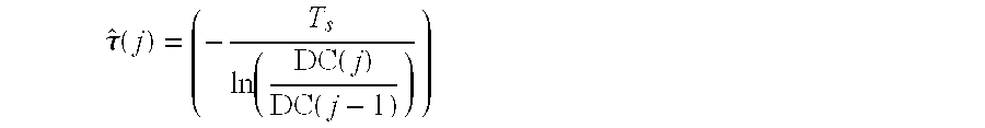
wherein FFT represents a fast fourier transform, j represents a current time index, L represents the number of sample points (either of the of the FFT of equation 3a or of the window of equation 4), iphase represents the phase current for one phase, m represents the harmonic order of the estimate, DC(j) represents a direct current average value (that is, for example, in equation 3b a direct current value of the FFA and in equation 4 an average of the last L samples of the phase current), p represents an index, TS represents the sampling period, and ln represents the natural logarithm.
Next the initial fault current magnitude is estimated at the instant of the fault. According to one embodiment of the present invention the estimation is performed by the following equation: A ^ ( j ) = DC ( j ) ( j - L - 1 ) T s τ ^ ( j ) . (6a)
Figure US06597999-20030722-M00002
In an alternative embodiment, the initial fault current magnitude is estimated using recursion: A ^ ( j ) = A ^ ( j - 1 ) * τ ^ ( j ) τ ^ ( j - 1 ) * DC ( j ) DC ( j - 1 ) T s τ ^ ( j ) * ( - ( L - 1 ) * T s τ ^ ( j ) - 1 ) / ( - ( L - 1 ) * T s τ ^ ( j - 1 ) - 1 ) . (6b)
Figure US06597999-20030722-M00003
This embodiment requires more complex calculations but can be less sensitive to noise in the measurement. Because DC(j) decays with time, the parameter estimations also degrade with time. Recursion improves the estimates. In both the non-recursive and recursive embodiments, the parameter estimations can be recalculated during about two to about three cycles and then held as fixed estimations.
Then phase angle θ is estimated and used to estimate the sinusoidal components B and C. In one embodiment, for example, the estimation is performed by using the first two terms of a fast fourier transform (FFT) of the measured fault current and subtracting the estimated DC offset current. For example, the following equations can be used: i ^ DC ( j ) = A ^ kT s τ ^ ( j ) , ( 7 )
Figure US06597999-20030722-M00004
AC(j)=i phase(j)−î DC(j),  (8)
θ(j)=θ(j−1)+ωT s,  (9)
B ^ ( j ) = 2 ω T s π i = 1 L i ^ AC ( j - i + 1 ) cos ( θ ( k ) ) , and ( 10 ) C ^ ( j ) = 2 ω T s π i = 1 L i ^ AC ( j - i + 1 ) sin ( θ ( k ) ) , ( 11 )
Figure US06597999-20030722-M00005
wherein i represents an index value.
The recursive forms of equations (10) and (11) as described in (11a), (11b) respectively can be alternately used: C ^ ( j ) = C ^ ( j - 1 ) + 2 ω T s π ( i ^ AC ( j ) sin ( θ ( j ) ) - i ^ AC ( j - L + 1 ) sin ( θ ( j - L + 1 ) ) ) (11a) B ^ ( j ) = B ^ ( j - 1 ) + 2 ω T s π ( i ^ AC ( j ) cos ( θ ( j ) ) - i ^ AC ( j - L + 1 ) cos ( θ ( j - L + 1 ) ) ) (11b)
Figure US06597999-20030722-M00006
Controller 26 of FIG. 1 may comprise a digital signal processor or other type of computer, for example, and may be included in controls of an associated switching device or in a separate unit. Switching device applications will benefit from the robust implementation, and the feedback of the prediction technique will provide improved immunity to noise. Also, errors due to the presence of current harmonics and other non-idealities such as numerical sensitivity, and sampling process aliasing and quantization can be reduced by using one of the closed loop techniques that are described below.
After estimating the parameters, attempts can be made to solve equation 1 for I(t)=0 to obtain zero crossing information. However, convergence to a solution of equation 1 can be a time-consuming process. Further, solving equation 1 provides multiple solutions due to the sine and cosine terms. In preferred embodiments of the present invention, zero crossing predictions are achieved without directly solving the transcendental equation modeling the fault current.
FIG. 3 is a flow chart of process steps for execution in the controller in conjunction with the process steps of FIG. 2 in accordance with a first more specific embodiment of the present invention, and FIG. 4 is a time line for further illustrating the embodiment of FIG. 3. This embodiment of the invention includes an efficient method for indirectly solving, in real-time, a transcendental equation that models the behavior of a fault current and improves the reliability of switching devices such as circuit breakers by reducing arcing and has the advantage that the only sensors required are current sensors that are typically already present.
In this embodiment, zero crossings for each phase are each predicted using the estimated parameters for each respective fault current by selecting an initial time interval in which a zero crossing is present (step 52), identifying a portion of the interval that includes the zero crossing (step 54), changing the interval to comprise the identified portion (step 56), and determining whether the changed interval provides a desired resolution (step 58). If the changed interval does not, the identifying, changing, and determining are sequentially performed until the changed interval provides the desired resolution.
According to a bisection embodiment of the present invention, the sign of current I(t) is evaluated at two time points t1 and t2 (interval (t1, t2)). The bisection method is applicable because the fault currents change polarity at each zero crossing. The identified time points and interval between them has the property that I(t1)*I(t2)<0. In applications with a large DC offset, t2=t1+π/ω is expected to provide an interval in which the zero crossing falls.
Current I(t) is next evaluated at t3 wherein t3 is defined by:
t 3=(t 2−(t 2 −t 1)/2).  (12)
That is, wherein t3 is the mid-point of the original interval. Alternatively, t3 can be situated anywhere within the interval, and, if desired, multiple time points between t1 and t2 can be used when identifying the portion of the interval with the zero crossing.
For the mid-point embodiment, the product of the signs of I(t3) and I(t2) is used to determine whether the interval of interest becomes (t3,t2) or (t1,t3). If I(t3)*I(t2) is less than zero, then the interval of interest becomes (t3,t2). Otherwise, the interval of interest becomes (t1,t3). Alternatively, the product of I(t3) and I(t1) can be used to select the interval of interest by determining that if I(t3)*I(t1) is less than zero, then the interval of interest becomes (t1,t3), else the interval of interest becomes (t3,t2).
The process of narrowing the interval is repeated iteratively with the data from the same zero crossing until the desired resolution Tw is achieved and it can thus be determined that the zero crossing is within the sufficiently-narrow final interval (step 60). Tw will typically be less than or equal to about 100 microseconds. For example, t4 can be calculated to be the time instant half way between the selected t1 and t3 or t3 and t2 points and the currents can be calculated and multiplied to determine the next interval in the same manner as discussed above. In the example of FIG. 4, the crossing lies between t4 and t6.
The selection of the initial two time points t1 and t2 will depend on the estimations of parameters τ, A, B, and C and will be unique to each zero crossing. In one embodiment, the t1 and t2 time points associated with the first zero crossing of interest are estimated by first rewriting
B cos(ωt)+C sin(ωt)  (13)
as
D*cos(ωt−φ)  (14)
wherein
D={square root over (B2+C2)}  (15)
and
φ=a tan(C/B).  (16)
For most faults, the DC offset is in the range of about 10 percent to about 15 percent. Thus the zero of equation 1 will fall near to the zero of equation 14. That is, near to:
t={circumflex over (φ)}/ω+n*π/2  (17)
wherein n=0(for first post-fault crossing), 1, 3, 5, 7, 9, 11, 13 . . .
For the initial first interval, t1 and t2 can be estimated as:
t 1={circumflex over (φ)}/ω−Δ,  (18)
and
t 2={circumflex over (φ)}/ω+Δ,  (19)
wherein Δ is a number which is adjusted according to the uncertainty of the φ estimate. Higher uncertainties lead to higher Δs.
Next the currents at t1 and t2 are calculated as:
I(t 1)=Ae (−t1/τ)+ D*cos(ωt 1−φ),  (20)
and
I(t 2)=Ae (−t2/τ)+ D*cos(ωt 2−φ)  (21)
If I(t1)*I(t2)<0, then the predicted current has crossed zero between the two time instants t1and t2.
The initial interval for the second zero crossing can be calculated using equation 17 as follows:
t 1={circumflex over (φ)}/ω+π−Δ,  (22)
and
t 2={circumflex over (φ)}/ω+π+Δ,  (23)
Similarly, the initial interval for the third zero crossing can be calculated using equation 17 as follows:
t 1={circumflex over (φ)}/ω+3*π/2−Δ,  (24)
and
t 2={circumflex over (φ)}/ω+3π/2+Δ.  (25)
The value of Δ can either remain constant (for an open loop embodiment) or change with later crossings (for a closed loop embodiment). The advantage to reducing Δ depends on the number of iterations used to get to the solution for the earlier zero crossing.
In a closed loop embodiment, depending on the magnitude of the t1 and t2 instants associated with subsequent zero crossings, the number of iterations can be reduced. Intervals of subsequent zero crossings can benefit from earlier data rather than using the above equations that are based on φ and ω. For example, these intervals can start out in the area of a second or later iteration. The number of iterations N required to produce a prediction of a zero crossing within window Tw is given by:
N=ln2((t 2 −t 1)/T w).  (26)
wherein ln2 represents a logarithm to base 2.
Once the final interval is determined, it can be assumed for all practical purposes that the zero crossing will occur in the identified interval and be within the window Tw. Optionally, the zero crossing could arbitrarily be declared as occurring at the midpoint of the final identified interval.
Estimates of the parameters can change over time. For improved accuracy, the parameters and φ can be recalculated. If the parameters A, τ, B, and C are continuously recalculated, equation 16 can be recalculated to improve the accuracy of the φ calculation and the accuracy of the zero crossing prediction.
In another optional embodiment, a correction factor can be used to improve the selection of initial intervals for subsequent zero crossing determinations. In this embodiment, the actual zero crossing (tT) is measured by the current sensors and used with its respective interval for improving the selection of a subsequent interval. For example:
t 1(2nd)=t 1(1st)+π/ω+(t T−(t 1(1st)+t 2(1st))/2),  (26a)
and
t 2(2nd)=t 2(1st)+π/ω+(t T−(t 1(1st)+t 2(1st))/2)  (26b)
can be used for setting the initial interval for the second zero crossing. Equations 26a and 26b are useful if the actual zero crossing is within the initial interval. If the actual zero crossing was not within the initial interval, then the size of subsequent initial intervals is increased to a sufficient degree such that the actual zero crossings lie within them.
FIG. 5 is a flow chart of process steps for execution in the controller in conjunction with the process steps of FIG. 2 in accordance with a second more specific embodiment of the present invention, and FIGS. 6 and 7 are graphs of simulation results of the embodiment of FIG. 5.
In the embodiment of FIG. 5, the estimated parameters for each respective fault current is used to predict the zero crossing of the respective fault current by predicting a predicted post-fault current zero crossing (step 62), determining an actual post-fault current zero crossing (step 64), determining a difference between the predicted and actual post fault current zero crossing, and using the difference to predict an additional post-fault current zero crossing, the additional crossing occurring subsequent to the predicted crossing. More particularly, using the difference in one embodiment comprises using the difference to estimate a correction factor (step 66) and then using the correction factor to predict the additional crossing (step 68).
In the embodiment of FIG. 5, a preliminary prediction tzero,n of the nth post-fault current zero crossing can be calculated as:
t zero,n =nπ/ω+a tan 2(C/B).  (27)
In distribution networks, a range of about three to about five cycles (windows) of operation is the regime of interest with each cycle including two zero crossings. In one embodiment of the present invention, at the kth post-fault zero crossing, the time error between the predicted and the actual kth zero crossing is measured. Based on this error, a correction term is added to modify the predicted nth zero crossing as
t zero,n,new =nπ/ω+a tan 2(C/B)+f(t zero,k,actual −t zero,k,predicted)  (28)
with the indexes n and k such that k is less than or equal to n−1. The function can be derived in any appropriate manner. Three example alternative functions are:
f(t zero,k,actual −t zero,k,predicted)=t zero,k,actual −t zero,k,predicted  (29)
f(t zero,k,actual −t zero,k,predicted)=sign(t zero,k,actual −t zero,k,predicted)*(t zero,k,actual −t zero,k,predicted)  (30)
f(t zero,k,actual −t zero,k,predicted)=sign((t zero,k,actual −t zero,k,predicted)*(t zero,k,actual −t zero,k,predicted)*abs(t zero,k,actual −t zero,k,predicted))  (31)
wherein sign(x)=1 if x>0 and sign(x)=−1 if x<0 and sign(0)=0 and abs represents absolute value.
Simulation results are shown in FIGS. 6-7 with FIG. 6 representing an embodiment with a signal-to-noise ratio of 240 decibels and FIG. 7 representing an embodiment with a signal-to-noise ratio of 60 decibels. For the embodiment of FIG. 6, each of the zero crossings after the first post-fault zero crossing was predicted at a value within 0.2 milliseconds of the true zero crossing. For the embodiment of FIG. 7, each of the zero crossings after the first post-fault zero crossing was predicted at a value within 0.4 milliseconds of the true zero crossing.
While only certain features of the invention have been illustrated and described herein, many modifications and changes will occur to those skilled in the art. It is, therefore, to be understood that the appended claims are intended to cover all such modifications and changes as fall within the true spirit of the invention.

Claims (26)

What is claimed is:
1. A method for predicting zero crossings of a fault current in a power system comprising:
sensing the fault current;
estimating parameters of a model of the fault current; and
using the estimated parameters to predict a zero crossing of the fault current by
(a) selecting an initial time interval in which a zero crossing is present,
(b) identifying a portion of the interval that includes the zero crossing,
(c) changing the interval to comprise the identified portion, and
(d) determining whether the changed interval provides a desired resolution, and, if not, cycling through elements (b)-(d) until the changed interval provides the desired resolution.
2. The method of claim 1 further including determining first and second signs of the fault current at two points of an initial time interval.
3. The method of claim 2 wherein identifying a portion of the interval that includes the zero crossing includes determining at least one additional sign of the fault current for at least one point between the two points of the interval and multiplying the at least one additional sign by the first or second sign and evaluating the sign of the resulting product.
4. A method for predicting zero crossings of a fault current in a power system comprising:
sensing the fault current;
estimating parameters of a model of the fault current; and
using the estimated parameters to predict a zero crossing of the fault current by
(a) predicting a predicted post-fault current zero crossing,
(b) determining an actual post-fault current zero crossing,
(c) determining a difference between the predicted and actual post fault current zero crossing, and
(d) using the difference to predict an additional post-fault current zero crossing, the additional crossing occurring subsequent to the predicted crossing.
5. The method of claim 4 wherein using the difference comprises using the difference to estimate a correction factor and then using the correction factor to predict the additional crossing.
6. A method for predicting zero crossings of fault currents in a multi-phase power system comprising:
sensing a fault current in each respective phase;
estimating parameters of a model of each respective fault current, wherein estimating the parameters of each respective fault current includes, for each respective fault current,
obtaining a direct current average value (DC(j-1)) of the current at a first sampling instant,
obtaining a direct current average value (DC(j)) of the current at a second sampling instant,
calculating the following equation to obtain a direct current offset decay time constant ({circumflex over (τ)}(j)): τ ^ ( j ) = ( - T s ln ( DC ( j ) DC ( j - 1 ) ) )
Figure US06597999-20030722-M00007
wherein Ts represents a sampling frequency of the sensed fault current; and
independently using the estimated parameters for each respective fault current to predict a zero crossing of the respective fault current.
7. The method of claim 6 wherein estimating the parameters of each respective fault current further includes, for each respective fault current, solving the following equation to obtain an initial fault current magnitude (Â(j)): A ^ ( j ) = DC ( j ) ( j - L - 1 ) T s τ ^ ( j )
Figure US06597999-20030722-M00008
wherein L represents a number of sample points.
8. A method for predicting zero crossings of fault currents in a multi-phase power system comprising:
sensing a fault current in each respective phase;
independently using the estimated parameters for each respective fault current to predict a zero crossing of the respective fault current, wherein independently using the estimated parameters for each respective fault current to predict the zero crossings of the respective fault current includes
(a) selecting an initial time interval in which a zero crossing is present,
(b) identifying a portion of the interval that includes the zero crossing,
(c) changing the interval to comprise the identified portion,
(d) determining whether the changed interval provides a desired resolution, and, if not, cycling through elements (b)-(d) until the changed interval provides the desired resolution.
9. The method of claim 8 further including determining first and second signs of the respective fault current at two points of an initial time interval.
10. The method of claim 9 wherein identifying a portion of the interval that includes the zero crossing includes determining at least one additional sign of the respective fault current for at least one point between the two points of the interval and multiplying the at least one additional sign by the first or second sign and evaluating the sign of the resulting product.
11. The method of claim 10 wherein the at least one additional sign comprises one additional sign and wherein the at least one point comprises a mid-point.
12. The method of claim 8 wherein the parameters include a sine component Ĉ and a cosine component {circumflex over (B)} and wherein selecting an initial time interval in which a zero crossing is present includes, for a first post-fault zero crossing, performing the following equations:
t 1={circumflex over (φ)}/ω+−Δ, and
t 2={circumflex over (φ)}/ω+Δ,
wherein {circumflex over (φ)} represents an archtangent of Ĉ/{circumflex over (B)}, ω represents an angular frequency of the fault current, and Δ represents an uncertainty factor.
13. The method of claim 12 wherein selecting an initial time interval in which a zero crossing is present includes, for a post-fault zero crossing subsequent to the first post-fault zero crossing, performing the following equations:
t 1={circumflex over (φ)}/ω+n*π/2−Δ, and
t 2={circumflex over (φ)}/ω+n*π/2+Δ,
wherein n is an odd integer (1, 3, 5, 7, 9, . . . ).
14. The method of claim 13 wherein selecting an initial time interval in which a zero crossing is present for a post-fault zero crossing subsequent to the first post-fault zero crossing further includes recalculating {circumflex over (φ)} for the post fault zero crossing subsequent to the first post fault zero crossing.
15. The method of claim 8 wherein selecting an initial time interval in which a zero crossing is present includes, for a post-fault zero crossing subsequent to a first post-fault zero crossing, using information obtained from calculations associated with the first post-fault zero crossing.
16. A method for predicting zero crossings of fault currents in a multi-phase power system comprising:
sensing a fault current in each respective phase;
estimating parameters of a model of each respective fault current; and
independently using the estimated parameters for each respective fault current to predict a zero crossing of the respective fault current wherein independently using the estimated parameters for each respective fault current to predict the zero crossings of the respective fault current includes
predicting a predicted post-fault current zero crossing,
determining an actual post-fault current zero crossing,
determining a difference between the predicted and actual post-fault current zero crossing, the additional crossing occurring subsequent to the predicted crossing.
17. The method of claim 16 wherein using the difference comprises using the difference to estimate a correction factor and then using the correction factor to predict the additional crossing.
18. A system for predicting zero crossings of fault currents in a multi-phase power system comprising:
means for determining a fault current in each respective phase;
means for estimating parameters of a model of each respective fault current; and
means for independently using the estimated parameters for each respective fault current to predict a zero crossing of the respective fault current, wherein the means for independently using the estimated parameters for each respective fault current to predict the zero crossings of the respective fault current includes
(a) means for selecting an initial time interval in which a zero crossing is present,
(b) means for identifying a portion of the interval that includes the zero crossing,
(c) means for changing the interval to comprise the identified portion,
(d) means for determining whether the changed interval provides a desired resolution, and, if not,
(e) means for cycling through the functions performed by the means (b)-(d) until the changed interval provides the desired resolution.
19. A system for predicting zero crossings of fault currents in a multi-phase power system comprising:
means for determining a fault current in each respective phase;
means for estimating parameters of a model of each respective fault current; and
means for independently using the estimated parameters for each respective fault current to predict a zero crossing of the respective fault current, wherein the means for independently using the estimated parameters for each respective fault current to predict the zero crossings of the respective fault current includes
means for predicting a predicted post-fault current zero crossing,
means for determining an actual post-fault current zero crossing,
means for determining a difference between the predicted and actual post fault current zero crossing,
means for using the difference to predict an additional post-fault current zero crossing, the additional crossing occurring subsequent to the predicted crossing.
20. A system for predicting zero crossings of fault currents in a multi-phase power system comprising:
means for determining a fault current in each respective phase;
means for estimating parameters of a model of each respective fault current; and
means for independently using the estimated parameters for each respective fault current to predict a zero crossing of the respective fault current, wherein the controller is adapted to estimate the parameters of each respective fault current by, for each respective fault current,
obtaining a direct current average value (DC(j-1)) of the current at a first sampling instant,
obtaining a direct current average value (DC(j)) of the current at a second sampling instant,
calculating the following equation to obtain a direct current offset decay time constant ({circumflex over (τ)}(j)): τ ^ ( j ) = ( - T s ln ( DC ( j ) DC ( j - 1 ) ) )
Figure US06597999-20030722-M00009
wherein Ts represents a sampling frequency of the sensed fault current.
21. The system of claim 20 wherein the controller is further adapted to estimate parameters of each respective fault current by, for each respective fault current, solving the following equation to obtain an initial fault current magnitude (Â(j)): A ^ ( j ) = DC ( j ) ( j - L - 1 ) T s τ ^ ( j )
Figure US06597999-20030722-M00010
wherein L represents a number of sample points in one fundamental cycle of the power system.
22. A system for predicting zero crossings of fault currents in a multi-phase power system comprising:
means for determining a fault current in each respective phase;
means for estimating parameters of a model of each respective fault current; and
means for independently using the estimated parameters for each respective fault current to predict a zero crossing of the respective fault current, wherein the controller is adapted to independently use the estimated parameters for each respective fault current to predict the zero crossings of the respective fault current by
(a) selecting an initial time interval in which a zero crossing is present,
(b) identifying a portion of the interval that includes the zero crossing,
(c) changing the interval to comprise the identified portion,
(d) determining whether the changed interval provides a desired resolution, and, if not, cycling through elements (b)-(d) until the changed interval provides the desired resolution.
23. The method of claim 22 wherein the parameters include a sine component Ĉ and a cosine component {circumflex over (B)} and wherein the controller is adapted to select an initial time interval in which a zero crossing is present by, for a first post-fault zero crossing, performing the following equations:
t 1={circumflex over (φ)}/ω+−Δ, and
t 2={circumflex over (φ)}/ω+Δ,
wherein {circumflex over (φ)} represents an archtangent of Ĉ/{circumflex over (B)}, ω represents an angular frequency of the fault current, and Δ represents an uncertainty factor.
24. The system of claim 22 wherein the controller is adapted to select an initial time interval in which a zero crossing is present by, for a post-fault zero crossing subsequent to a first post-fault zero crossing, using information obtained from calculations associated with the first post-fault zero crossing.
25. A system for predicting zero crossings of fault currents in a multi-phase power system comprising:
means for determining a fault current in each respective phase;
means for estimating parameters of a model of each respective fault current; and
means for independently using the estimated parameters for each respective fault current to predict a zero crossing of the respective fault current, wherein the controller is adapted to independently use the estimated parameters for each respective fault current to predict the zero crossing of the respective fault current by
predicting a predicted post-fault current zero crossing,
determining an actual post-fault current zero crossing,
determining a difference between the predicted and actual post-fault current zero crossing, and
using the difference to predict an additional post-fault current zero crossing, the additional crossing occurring subsequent to the predicted crossing.
26. The system of claim 25 wherein the computer is adapted to use the difference by using the difference to estimate a correction factor and then using the correction factor to predict the additional crossing.
US09/467,139 1999-12-20 1999-12-20 Method and system for real-time prediction of zero crossings of fault currents Expired - Lifetime US6597999B1 (en)

Priority Applications (1)

Application Number Priority Date Filing Date Title
US09/467,139 US6597999B1 (en) 1999-12-20 1999-12-20 Method and system for real-time prediction of zero crossings of fault currents

Applications Claiming Priority (1)

Application Number Priority Date Filing Date Title
US09/467,139 US6597999B1 (en) 1999-12-20 1999-12-20 Method and system for real-time prediction of zero crossings of fault currents

Publications (1)

Publication Number Publication Date
US6597999B1 true US6597999B1 (en) 2003-07-22

Family

ID=23854531

Family Applications (1)

Application Number Title Priority Date Filing Date
US09/467,139 Expired - Lifetime US6597999B1 (en) 1999-12-20 1999-12-20 Method and system for real-time prediction of zero crossings of fault currents

Country Status (1)

Country Link
US (1) US6597999B1 (en)

Cited By (22)

* Cited by examiner, † Cited by third party
Publication number Priority date Publication date Assignee Title
US20040090719A1 (en) * 2000-06-07 2004-05-13 Per Larsson Method and device for prediction of a zero-crossing alternating current
EP1739697A3 (en) * 2003-02-28 2007-06-13 EATON Corporation Method and apparatus to control modular asynchronous contactors
US20070192078A1 (en) * 2006-02-14 2007-08-16 Edsa Micro Corporation Systems and methods for real-time system monitoring and predictive analysis
US20070213956A1 (en) * 2006-03-10 2007-09-13 Edsa Micro Corporation Systems and methods for real-time protective device evaluation in an electrical power distribution system
EP1854113A1 (en) * 2004-10-22 2007-11-14 ABB Technology Ltd An apparatus and a method for predicting a fault current
EP1928007A1 (en) * 2006-12-01 2008-06-04 ABB Technology Ltd A method and apparatus for predicting the future behavior of current paths
US20080167844A1 (en) * 2006-03-10 2008-07-10 Edsa Micro Corporation Systems and methods for providing real-time predictions of arc flash incident energy, arc flash protection boundary, and required personal protective equipment (ppe) levels to comply with workplace safety standards
WO2008148428A1 (en) * 2007-06-08 2008-12-11 Abb Research Ltd Method and device to predict a state of a power system in the time domain
US20090113049A1 (en) * 2006-04-12 2009-04-30 Edsa Micro Corporation Systems and methods for real-time forecasting and predicting of electrical peaks and managing the energy, health, reliability, and performance of electrical power systems based on an artificial adaptive neural network
US20090207536A1 (en) * 2008-02-18 2009-08-20 Anderson Dennis R Method and apparatus for measuring dc current in an ac generator
US20100014197A1 (en) * 2006-07-15 2010-01-21 Deepstreem Technologies Ltd Method and apparatus of detecting and compensating for dc residual fault currents on electrical systems
US20100023309A1 (en) * 2008-07-18 2010-01-28 Edsa Micro Corporation Method for predicting symmetric, automated, real-time arc flash energy within a real-time monitoring system
US20100168931A1 (en) * 2006-04-12 2010-07-01 Edsa Micro Corporation Systems and methods for alarm filtering and management within a real-time data acquisition and monitoring environment
US20100324872A1 (en) * 2008-03-26 2010-12-23 Hsiao-Dong Chiang Stable equilibrium point (sep) calculation apparatus of power system
CN103454482A (en) * 2013-09-16 2013-12-18 国家电网公司 Method for calculating one-phase grounding full fault currents of small current grounding system
US9031824B2 (en) 2006-07-19 2015-05-12 Power Analytics Corporation Real-time predictive systems for intelligent energy monitoring and management of electrical power networks
US9092593B2 (en) 2007-09-25 2015-07-28 Power Analytics Corporation Systems and methods for intuitive modeling of complex networks in a digital environment
US20160301199A1 (en) * 2013-10-17 2016-10-13 Mitsubishi Electric Corporation Power switching control apparatus and switching control method therefor
US10211005B2 (en) 2016-11-21 2019-02-19 Schneider Electric USA, Inc. Cost reduced synchronized-switching contactor
US10867087B2 (en) 2006-02-14 2020-12-15 Wavetech Global, Inc. Systems and methods for real-time DC microgrid power analytics for mission-critical power systems
US10962999B2 (en) 2009-10-01 2021-03-30 Wavetech Global Inc. Microgrid model based automated real time simulation for market based electric power system optimization
US11113434B2 (en) 2006-02-14 2021-09-07 Power Analytics Corporation Method for predicting arc flash energy and PPE category within a real-time monitoring system

Citations (11)

* Cited by examiner, † Cited by third party
Publication number Priority date Publication date Assignee Title
US4148087A (en) * 1977-04-20 1979-04-03 Phadke Arun G Distance relay for electric power transmission lines
US4559491A (en) * 1982-09-14 1985-12-17 Asea Aktiebolag Method and device for locating a fault point on a three-phase power transmission line
US4642724A (en) * 1982-06-22 1987-02-10 S&C Electric Company Trip signal generator for a circuit interrupter
US4922363A (en) 1985-10-17 1990-05-01 General Electric Company Contactor control system
US5216621A (en) * 1991-02-28 1993-06-01 Mehta Tech. Inc. Line disturbance monitor and recorder system
US5430599A (en) 1993-03-18 1995-07-04 Hydro-Quebec System for opening/closing circuit breakers
US5440180A (en) 1992-09-28 1995-08-08 Eaton Corporation Microprocessor based electrical contactor with distributed contactor opening
US5563459A (en) 1989-11-15 1996-10-08 Hitachi, Ltd. Apparatus for controlling opening and closing timings of a switching device in an electric power system
US5638296A (en) 1994-04-11 1997-06-10 Abb Power T&D Company Inc. Intelligent circuit breaker providing synchronous switching and condition monitoring
US5793594A (en) * 1995-12-21 1998-08-11 S&C Electric Company Predictive control circuit and method for circuit interrupter
US5854729A (en) * 1997-05-23 1998-12-29 Utility Systems Technologies, Inc. Power system device and method for actively interrupting fault current before reaching peak magnitude

Patent Citations (12)

* Cited by examiner, † Cited by third party
Publication number Priority date Publication date Assignee Title
US4148087A (en) * 1977-04-20 1979-04-03 Phadke Arun G Distance relay for electric power transmission lines
US4642724A (en) * 1982-06-22 1987-02-10 S&C Electric Company Trip signal generator for a circuit interrupter
US4559491A (en) * 1982-09-14 1985-12-17 Asea Aktiebolag Method and device for locating a fault point on a three-phase power transmission line
US4922363A (en) 1985-10-17 1990-05-01 General Electric Company Contactor control system
US5563459A (en) 1989-11-15 1996-10-08 Hitachi, Ltd. Apparatus for controlling opening and closing timings of a switching device in an electric power system
US5216621A (en) * 1991-02-28 1993-06-01 Mehta Tech. Inc. Line disturbance monitor and recorder system
US5440180A (en) 1992-09-28 1995-08-08 Eaton Corporation Microprocessor based electrical contactor with distributed contactor opening
US5430599A (en) 1993-03-18 1995-07-04 Hydro-Quebec System for opening/closing circuit breakers
US5627415A (en) 1993-03-18 1997-05-06 Hydro-Quebec System and method for opening/closing circuit breakers
US5638296A (en) 1994-04-11 1997-06-10 Abb Power T&D Company Inc. Intelligent circuit breaker providing synchronous switching and condition monitoring
US5793594A (en) * 1995-12-21 1998-08-11 S&C Electric Company Predictive control circuit and method for circuit interrupter
US5854729A (en) * 1997-05-23 1998-12-29 Utility Systems Technologies, Inc. Power system device and method for actively interrupting fault current before reaching peak magnitude

Cited By (42)

* Cited by examiner, † Cited by third party
Publication number Priority date Publication date Assignee Title
US7010436B2 (en) * 2000-06-07 2006-03-07 Abb Group Services Center Ab Method and device for prediction of a zero-crossing alternating current
US20040090719A1 (en) * 2000-06-07 2004-05-13 Per Larsson Method and device for prediction of a zero-crossing alternating current
EP1739697A3 (en) * 2003-02-28 2007-06-13 EATON Corporation Method and apparatus to control modular asynchronous contactors
EP1854113A1 (en) * 2004-10-22 2007-11-14 ABB Technology Ltd An apparatus and a method for predicting a fault current
EP1854113A4 (en) * 2004-10-22 2010-11-17 Abb Technology Ltd An apparatus and a method for predicting a fault current
US20100262411A1 (en) * 2006-02-14 2010-10-14 Edsa Micro Corporation Systems and methods for real-time system monitoring and predictive analysis
US11113434B2 (en) 2006-02-14 2021-09-07 Power Analytics Corporation Method for predicting arc flash energy and PPE category within a real-time monitoring system
US20070192078A1 (en) * 2006-02-14 2007-08-16 Edsa Micro Corporation Systems and methods for real-time system monitoring and predictive analysis
US7826990B2 (en) 2006-02-14 2010-11-02 Edsa Micro Corporation Systems and methods for real-time system monitoring and predictive analysis
US8155908B2 (en) 2006-02-14 2012-04-10 Power Analytics Corporation Systems and methods for real-time system monitoring and predictive analysis
US10867087B2 (en) 2006-02-14 2020-12-15 Wavetech Global, Inc. Systems and methods for real-time DC microgrid power analytics for mission-critical power systems
US7844439B2 (en) 2006-03-10 2010-11-30 Edsa Micro Corporation Systems and methods for real-time protective device evaluation in an electrical power distribution system
US20070213956A1 (en) * 2006-03-10 2007-09-13 Edsa Micro Corporation Systems and methods for real-time protective device evaluation in an electrical power distribution system
US7729808B2 (en) 2006-03-10 2010-06-01 Edsa Micro Corporation System for comparing real-time data and modeling engine data to predict arc flash events
US20080167844A1 (en) * 2006-03-10 2008-07-10 Edsa Micro Corporation Systems and methods for providing real-time predictions of arc flash incident energy, arc flash protection boundary, and required personal protective equipment (ppe) levels to comply with workplace safety standards
WO2007106430A3 (en) * 2006-03-10 2008-06-26 Edsa Micro Corp Systems and methods for real- time protective device evaluation in an electrical power distribution system
US8577661B2 (en) * 2006-04-12 2013-11-05 Power Analytics Corporation Systems and methods for alarm filtering and management within a real-time data acquisition and monitoring environment
US20090113049A1 (en) * 2006-04-12 2009-04-30 Edsa Micro Corporation Systems and methods for real-time forecasting and predicting of electrical peaks and managing the energy, health, reliability, and performance of electrical power systems based on an artificial adaptive neural network
US20100168931A1 (en) * 2006-04-12 2010-07-01 Edsa Micro Corporation Systems and methods for alarm filtering and management within a real-time data acquisition and monitoring environment
US20100014197A1 (en) * 2006-07-15 2010-01-21 Deepstreem Technologies Ltd Method and apparatus of detecting and compensating for dc residual fault currents on electrical systems
US8340829B2 (en) * 2006-07-15 2012-12-25 Eaton Industries Manufacturing Gmbh Method and apparatus of detecting and compensating for DC residual fault currents on electrical systems
US9557723B2 (en) 2006-07-19 2017-01-31 Power Analytics Corporation Real-time predictive systems for intelligent energy monitoring and management of electrical power networks
US9031824B2 (en) 2006-07-19 2015-05-12 Power Analytics Corporation Real-time predictive systems for intelligent energy monitoring and management of electrical power networks
EP1928007A1 (en) * 2006-12-01 2008-06-04 ABB Technology Ltd A method and apparatus for predicting the future behavior of current paths
CN101542662B (en) * 2006-12-01 2011-06-15 Abb技术有限公司 A method and an apparatus for predicting the future behavior of currents in current paths
WO2008064946A1 (en) * 2006-12-01 2008-06-05 Abb Technology Ag A method and an apparatus for predicting the future behavior of currents in current paths
WO2008148428A1 (en) * 2007-06-08 2008-12-11 Abb Research Ltd Method and device to predict a state of a power system in the time domain
CN101688892B (en) * 2007-06-08 2012-07-25 Abb研究有限公司 Method and device to predict a state of a power system in the time domain
US8095326B2 (en) * 2007-06-08 2012-01-10 Abb Research Ltd. Method and device to predict a state of a power system in the time domain
US20100088048A1 (en) * 2007-06-08 2010-04-08 Bertil Berggren Method And Device To Predict A State Of A Power System In The Time Domain
US9092593B2 (en) 2007-09-25 2015-07-28 Power Analytics Corporation Systems and methods for intuitive modeling of complex networks in a digital environment
US20090207536A1 (en) * 2008-02-18 2009-08-20 Anderson Dennis R Method and apparatus for measuring dc current in an ac generator
US7948723B2 (en) * 2008-02-18 2011-05-24 Hamilton Sundstrand Corporation Method and apparatus for measuring DC current in an AC generator
US20100324872A1 (en) * 2008-03-26 2010-12-23 Hsiao-Dong Chiang Stable equilibrium point (sep) calculation apparatus of power system
US8326589B2 (en) * 2008-03-26 2012-12-04 The Tokyo Electric Power Company, Incorporated Stable equilibrium point (SEP) calculation apparatus of power system
US8494830B2 (en) 2008-07-18 2013-07-23 Power Analytics Corporation Method for predicting symmetric, automated, real-time Arc Flash energy within a real-time monitoring system
US20100023309A1 (en) * 2008-07-18 2010-01-28 Edsa Micro Corporation Method for predicting symmetric, automated, real-time arc flash energy within a real-time monitoring system
US10962999B2 (en) 2009-10-01 2021-03-30 Wavetech Global Inc. Microgrid model based automated real time simulation for market based electric power system optimization
CN103454482A (en) * 2013-09-16 2013-12-18 国家电网公司 Method for calculating one-phase grounding full fault currents of small current grounding system
US20160301199A1 (en) * 2013-10-17 2016-10-13 Mitsubishi Electric Corporation Power switching control apparatus and switching control method therefor
US10177553B2 (en) * 2013-10-17 2019-01-08 Mitsubishi Electric Corporation Power switching control apparatus and switching control method therefor
US10211005B2 (en) 2016-11-21 2019-02-19 Schneider Electric USA, Inc. Cost reduced synchronized-switching contactor

Similar Documents

Publication Publication Date Title
US6597999B1 (en) Method and system for real-time prediction of zero crossings of fault currents
US8198904B2 (en) Synchrophasor measuring device and inter-bus-line phase angle difference measurement unit using the same
US6519537B1 (en) Apparatus providing on-line indication of frequency of an AC electric power system
Zadeh et al. Combination of Kalman filter and least-error square techniques in power system
US8373309B2 (en) Systems and methods for asynchronous sampling data conversion
US10545184B2 (en) Directional detection of earth faults in an electrical distribution network
US5060166A (en) Method and apparatus for rapidly analyzing AC waveforms containing DC offsets
US6185482B1 (en) System and method for rms overcurrent backup function
WO2007135073A2 (en) Detecting faults in power systems
US20190296543A1 (en) Method for detecting fault in power transmission line and protection system using the same
EP0787304A1 (en) Numerical comparator
Abdolkhalig et al. Phasor measurement based on IEC 61850-9-2 and Kalman–Filtering
Zadeh et al. Online estimation of distorted power system signal parameters
Terzija et al. Symmetrical components estimation through nonrecursive Newton-type numerical algorithm
Eissa A novel wavelet approach to busbar protection during CT saturation and ratio-mismatch
Terzija Improved recursive Newton-type algorithm for power system relaying and measurement
Xu et al. Real-time measurement of mean frequency in two-machine system during power swings
Petruzziello et al. Some implementation aspects of line current reconstruction in three phase PWM inverters
El-Naggar A fast method for identification of symmetrical components for power system protection
Olejnik Alternative method of determining zero-sequence voltage for fault current passage indicators in overhead medium voltage networks
JP2000341847A (en) Tripping device using phase reconfiguration and breaker therewith
Abdolkhalig et al. Evaluation of IEC 61850-9-2 samples loss on total vector error of an estimated phasor
EP0367563B1 (en) Detector of quantity of electricity
Terzija et al. Detection of arcing faults: modelling, simulation, testing and algorithms aspects
Moreto et al. Using disturbance records to automate the diagnosis of faults and operational procedures in power generators

Legal Events

Date Code Title Description
AS Assignment

Owner name: GENERAL ELECTRIC COMPANY, NEW YORK

Free format text: ASSIGNMENT OF ASSIGNORS INTEREST;ASSIGNORS:SINHA, GAUTAM (NMN);PREMERLANI, WILLIAM JAMES;VLATKOVIC, VLATKO (NMN);REEL/FRAME:010478/0500;SIGNING DATES FROM 19991210 TO 19991214

STCF Information on status: patent grant

Free format text: PATENTED CASE

FEPP Fee payment procedure

Free format text: PAYOR NUMBER ASSIGNED (ORIGINAL EVENT CODE: ASPN); ENTITY STATUS OF PATENT OWNER: LARGE ENTITY

CC Certificate of correction
REMI Maintenance fee reminder mailed
FPAY Fee payment

Year of fee payment: 4

SULP Surcharge for late payment
REMI Maintenance fee reminder mailed
FPAY Fee payment

Year of fee payment: 8

SULP Surcharge for late payment

Year of fee payment: 7

FPAY Fee payment

Year of fee payment: 12