US6596025B2 - Narrow profile intraocular lens - Google Patents

Narrow profile intraocular lens Download PDF

Info

Publication number
US6596025B2
US6596025B2 US09/809,152 US80915201A US6596025B2 US 6596025 B2 US6596025 B2 US 6596025B2 US 80915201 A US80915201 A US 80915201A US 6596025 B2 US6596025 B2 US 6596025B2
Authority
US
United States
Prior art keywords
optic
intraocular lens
peri
zone
glare
Prior art date
Legal status (The legal status is an assumption and is not a legal conclusion. Google has not performed a legal analysis and makes no representation as to the accuracy of the status listed.)
Expired - Fee Related, expires
Application number
US09/809,152
Other versions
US20020161435A1 (en
Inventor
Valdemar Portney
Current Assignee (The listed assignees may be inaccurate. Google has not performed a legal analysis and makes no representation or warranty as to the accuracy of the list.)
OPTHALMIC LENDERS LLC
Aaren Scientific Inc
Original Assignee
Valdemar Portney
Priority date (The priority date is an assumption and is not a legal conclusion. Google has not performed a legal analysis and makes no representation as to the accuracy of the date listed.)
Filing date
Publication date
Application filed by Valdemar Portney filed Critical Valdemar Portney
Priority to US09/809,152 priority Critical patent/US6596025B2/en
Priority to EP02714803A priority patent/EP1370199A4/en
Priority to PCT/US2002/002712 priority patent/WO2002074210A2/en
Publication of US20020161435A1 publication Critical patent/US20020161435A1/en
Priority to US10/444,896 priority patent/US7204849B2/en
Application granted granted Critical
Publication of US6596025B2 publication Critical patent/US6596025B2/en
Assigned to OPTHALMIC LENDERS, LLC reassignment OPTHALMIC LENDERS, LLC ASSIGNMENT OF ASSIGNORS INTEREST (SEE DOCUMENT FOR DETAILS). Assignors: O.I.I. INTERNATIONAL, INC.
Assigned to WELLS FARGO BANK, NATIONAL ASSOCIATION (ACTING THROUGH WELLS FARGO BUSINESS CREDIT OPERATING DIVISION) reassignment WELLS FARGO BANK, NATIONAL ASSOCIATION (ACTING THROUGH WELLS FARGO BUSINESS CREDIT OPERATING DIVISION) SECURITY AGREEMENT Assignors: O.I.I. INTERNATIONAL, INC.
Assigned to AAREN SCIENTIFIC, INC. reassignment AAREN SCIENTIFIC, INC. MERGER (SEE DOCUMENT FOR DETAILS). Assignors: O.I.I. INTERNATIONAL, INC.
Assigned to WELLS FARGO BANK reassignment WELLS FARGO BANK FIRST AMENDMENT TO PATENT AND TRADEMARK SECURITY AGREEMENT Assignors: AAREN SCIENTIFIC, INC.
Adjusted expiration legal-status Critical
Expired - Fee Related legal-status Critical Current

Links

Images

Classifications

    • AHUMAN NECESSITIES
    • A61MEDICAL OR VETERINARY SCIENCE; HYGIENE
    • A61FFILTERS IMPLANTABLE INTO BLOOD VESSELS; PROSTHESES; DEVICES PROVIDING PATENCY TO, OR PREVENTING COLLAPSING OF, TUBULAR STRUCTURES OF THE BODY, e.g. STENTS; ORTHOPAEDIC, NURSING OR CONTRACEPTIVE DEVICES; FOMENTATION; TREATMENT OR PROTECTION OF EYES OR EARS; BANDAGES, DRESSINGS OR ABSORBENT PADS; FIRST-AID KITS
    • A61F2/00Filters implantable into blood vessels; Prostheses, i.e. artificial substitutes or replacements for parts of the body; Appliances for connecting them with the body; Devices providing patency to, or preventing collapsing of, tubular structures of the body, e.g. stents
    • A61F2/02Prostheses implantable into the body
    • A61F2/14Eye parts, e.g. lenses, corneal implants; Implanting instruments specially adapted therefor; Artificial eyes
    • A61F2/16Intraocular lenses
    • A61F2/1613Intraocular lenses having special lens configurations, e.g. multipart lenses; having particular optical properties, e.g. pseudo-accommodative lenses, lenses having aberration corrections, diffractive lenses, lenses for variably absorbing electromagnetic radiation, lenses having variable focus
    • AHUMAN NECESSITIES
    • A61MEDICAL OR VETERINARY SCIENCE; HYGIENE
    • A61FFILTERS IMPLANTABLE INTO BLOOD VESSELS; PROSTHESES; DEVICES PROVIDING PATENCY TO, OR PREVENTING COLLAPSING OF, TUBULAR STRUCTURES OF THE BODY, e.g. STENTS; ORTHOPAEDIC, NURSING OR CONTRACEPTIVE DEVICES; FOMENTATION; TREATMENT OR PROTECTION OF EYES OR EARS; BANDAGES, DRESSINGS OR ABSORBENT PADS; FIRST-AID KITS
    • A61F2/00Filters implantable into blood vessels; Prostheses, i.e. artificial substitutes or replacements for parts of the body; Appliances for connecting them with the body; Devices providing patency to, or preventing collapsing of, tubular structures of the body, e.g. stents
    • A61F2/02Prostheses implantable into the body
    • A61F2/14Eye parts, e.g. lenses, corneal implants; Implanting instruments specially adapted therefor; Artificial eyes
    • A61F2/16Intraocular lenses
    • A61F2/1602Corrective lenses for use in addition to the natural lenses of the eyes or for pseudo-phakic eyes

Definitions

  • the present invention relates generally to the field of ophthalmic devices, more particularly to intraocular lenses (IOLs), and still more particularly to thin profile monofocal refractive IOLs for implanting in narrow ocular regions, especially the anterior chamber of an eye.
  • IOLs intraocular lenses
  • thin profile monofocal refractive IOLs for implanting in narrow ocular regions, especially the anterior chamber of an eye.
  • phakic applies to an eye in which the natural crystalline lens is still present.
  • aphakic applies to an eye from which the natural crystalline lens has been surgically removed, for example, due to the formation of cataracts on the lens.
  • the anterior chamber of an eye is the narrow region between the back, endothelial surface of the cornea and the front surface of the iris.
  • the posterior chamber of a phakic eye is the narrow region between the back surface of the iris and the front surface of the natural crystalline lens.
  • a Fresnel lens (as defined at page 167 of the DICTIONARY OF OPTICS, published by Butterworth Heinemann, 1995) is “A lens surface of narrow concentric rings or prism sections of a specified power that gives the effect of a continuous lens surface with the same power, but without the usual thickness and weight.”
  • Glare (as defined at page 53 of THE GLOSSARY OF OPTICAL TERMINOLOGY, published by Professional Press Books, Fairchild Publications, 1986) is “Any degree of light falling on the retina in excess of that which enables one to see clearly.” And alternatively as “Any excess of light which hinders rather than helps vision. (Too much light in the wrong place.)”
  • Vision in a phakic eye is caused by light from a viewed object being refracted by the cornea and the natural crystalline lens to form an image on the retina at the back of the eye.
  • Corrective spectacles, contact lens or corneal reshaping may be used to assist such image formations
  • Optical muscles connected to a normal crystalline lens change the shape of the lens as needed to provide images of objects at different distances from the eye, an optical process known as accommodation.
  • IOL intraocular lens
  • IOLs for restoring vision in aphakic eyes
  • refractive IOLs and insertion instruments
  • the implanting of such corrective IOLs can potentially eliminate the wearing of spectacles or contact lenses, and/or eliminate permanent surgical procedures involving the cornea.
  • Anterior chamber-type IOLs may alternatively be implanted in posterior chambers of phakic eyes for providing corrective power to the natural lens, as may be needed due to subsequent physiological changes of the natural lens as an individual ages.
  • the anterior chamber is generally dome-shaped and very narrow—typically only about 3 mm at its center.
  • the posterior chamber of a phakic eye be even more narrow, depending upon the size of the crystalline lens and the amount of its accommodation the width of the posterior chamber of a phakic eye—the successful implanting of a corrective IOL in either of these ocular chambers is extremely difficult and risks injuring delicate ocular tissue, especially the cornea's endothelial surface in the case of anterior chamber implanting. Consequently, refractive corrective IOLs, particularly the IOL optics, are desirably made as thin as possible consistent with providing the requisite corrective power and structural stability of the optic.
  • U.S. Pat. No. 4,787,903 to Grendahl discloses a refractive IOL or corneal lens having an optic that incorporates a Fresnel lens with multiple, concentric ring-zones.
  • the Grendahl lens is further disclosed as being made of a composite material that allows refractive index modification with electromagnetic energy.
  • the Grendahl patent asserts a first use of a Fresnel lens for IOLs or corneal lenses, the Grendahl patent application having been filed shortly before the Schiegel patent application was filed).
  • U.S. Pat. No. 4,846,833 to Cumming discloses the forming of a Fresnel lens on the back surface of a posterior chamber IOL so the Fresnel surface will be sealed by the posterior capsule surface upon the implanting of the IOL in an aphakic eye.
  • U.S. Pat. No. 6,096,077 to Callahan et al. discloses a thin IOL having the posterior surface formed of a stepped series of annular concentric rings of increasing diameter surrounding a central planar disc region; although, the Callahan et al. patent does not specifically identify the IOL posterior surface as being a Fresnel lens, the associated figures indicate that such is the case.
  • IOLs having abrupt Fresnel zone transition steps with flat surfaces induce substantial distracting and potentially hazardous glare in the IOL wearer's eye when light (especially bright light) impinges on the lens optic as, for example, is commonly encountered in night driving or when driving into the sun.
  • a principal objective of the present invention is to provide a narrow profile (that is, thin) IOL, in particular, a narrow profile monofocal IOL that substantially minimizes such visual glare problems.
  • a narrow profile, glare reducing refractive monofocal intraocular lens comprises an optic having an anterior surface and a posterior surface and an optical axis.
  • One of the anterior and posterior surfaces is formed having adjacent first and second peri-axial, stepped imaging zones, the second peri-axial imaging zone having the substantially the same optical power as the first peri-optical imaging zone.
  • a transition zone between the first and second peri-axial imaging zones is preferably formed having a surface of continuous variable curvature so as to reduce both indirect glare (caused by refraction) and direct glare (caused by diffraction) in an individual's eye in which the intraocular lens is implanted from light impinging on the optic.
  • Positioning means are joined to the optic for positioning the intraocular lens in the eye with the optical axis of the optic generally aligned with the optical axis of the eye.
  • the first peri-axial imaging zone may be circular in shape and be centered at the optical axis of the optic and may have a diameter between about 4.3 mm and about 4.5 mm.
  • the second peri-axial imaging zone is in such case formed in annular ring around the first peri-axial imaging zone.
  • the first peri-axial imaging zone may be recessed in the optic relative to the second peri-axial imaging zone.
  • the second peri-axial imaging zone may be recessed in the optic relative to the first peri-axial imaging zone.
  • the first and second peri-axial imaging zones and the transition zone define one surface, preferably the posterior surface, of the optic that has a preferred maximum thickness at any point of between about 0.30 mm and about 0.40 mm.
  • the optical power of the peri-axial transition zones is preferably outside the diopter range of about ⁇ 5 to about +5.
  • the height of the transition zone is preferably between about 0.10 mm and about 0.40 mm and the width of the transition zone is preferably between about 0.15 mm and about 0.30 mm.
  • the transition zone surface has a continuous curvature that eliminates glare caused by diffraction and in another variation intraocular lens the transition zone has a surface of variable curvature that that reduces glare caused by refraction.
  • FIG. 1 is a partial cross sectional drawing of a representative prior art refractive intraocular lens employing a Fresnel lens on one surface of the optic, showing a sharp, flat step between a representative pair of adjacent Fresnel zones, showing several light rays obliquely incident on the front surface of the optic and showing the path of the light rays as they are refracted through the optic and out through the flat Fresnel zone step surface;
  • FIG. 2 is a cross sectional drawing of an eye in which the representative intraocular lens of FIG. 1 is implanted in the anterior chamber, and depicting a typical strong indirect glare pattern formed on a peripheral region of the eye's retina by the light rays that are obliquely incident on the sharp, flat Fresnel zone step as depicted in FIG. 1;
  • FIG. 3 is a partial cross sectional drawing, similar to FIG. 1, of a representative prior art refractive intraocular lens employing a Fresnel lens on one surface of the optic, showing a sharp, flat step between a representative pair of adjacent Fresnel zones, showing a single light ray perpendicularly incident on the front surface of the optic and showing the path of the light ray as it is refracted through the optic and is diffracted out of the optic at sharp corners of the sharp, flat Fresnel zone step surface;
  • FIG. 4 is a cross sectional drawing of an eye, similar to FIG. 2, in which the representative intraocular lens of FIG. 3 is implanted in the anterior chamber, and depicting the manner in which a direct glare pattern is formed at the image region of the retina by the diffracted light from the intraocular lens Fresnel zone step as depicted in FIG. 3;
  • FIG. 5 is a plan view of the posterior (back) surface of an intraocular lens of the present invention, showing the optic and an opposing pair of fixating members, showing a first, central imaging zone surrounded by a second imaging zone, and showing in dashed lines the transition zone between the two imaging zones;
  • FIG. 6 is a longitudinal cross sectional view looking along line 6 — 6 of FIG. 5, showing the optic as a concave-convex (meniscus) optic, showing the first and second imaging zones and the transition zone therebetween forming the posterior surface of the optic, showing the second, outer imaging zone recessed into the optic relative to the first, central imaging zone and showing in phantom lines the thicker shape that the optic would be without the recessed second imaging zone;
  • the optic is a concave-convex (meniscus) optic, showing the first and second imaging zones and the transition zone therebetween forming the posterior surface of the optic, showing the second, outer imaging zone recessed into the optic relative to the first, central imaging zone and showing in phantom lines the thicker shape that the optic would be without the recessed second imaging zone;
  • FIG. 7 is a longitudinal cross sectional view corresponding to FIG. 6, showing a variation optic as a bi-convex optic, showing the first and second imaging zones and the transition zone therebetween forming the posterior surface of the optic, showing the first, central, imaging zone recessed into the optic relative to the second imaging zone and showing in phantom lines the thicker shape that the optic would be without the recessed first imaging zone;
  • FIG. 8 is a an enlarged cross section of the transition zone of the intraocular lens optic of FIG. 6, showing the shape of a continuously variable curvature of the transition zone surface;
  • FIG. 9 is a cross sectional drawing similar to FIG. 8, depicting several light rays obliquely incident on the intraocular lens optic and showing the diverging of the light rays refracted by the optic through the transition zone surface;
  • FIG. 10 is a cross sectional drawing of an eye, similar to FIG. 2, showing a diffuse indirect glare region caused by the light rays diverging from the transition zone surface as depicted in FIG. 9;
  • FIG. 11 is a cross sectional drawing similar to FIG. 9, depicting several direct light rays incident on the intraocular lens optic and depicting the redirecting of light out of the image by utilization of internal reflection at the transition zone surface;
  • FIG. 12 is an enlarged cross sectional drawing, corresponding generally to FIG. 8, of a second variation transition zone of the intraocular lens optic of FIG. 6, showing the shape of a transition zone surface of variable curvature (instead of continuously variable curvature);
  • FIG. 13 is an enlarged cross sectional drawing, corresponding generally to FIG. 8, of a variation transition zone of the intraocular lens optic of FIG. 6, showing the shape of a transition zone surface of continuous curvature (instead of continuously variable curvature).
  • Glare caused by abrupt flat transition steps between Fresnel zones of lenses as disclosed in the above-cited patents may be indirect, direct, or combined indirect and direct, according to lighting conditions encountered by an individual in whose eye the intraocular lens is implanted. Indirect and direct glare are most likely to be encountered at night under driving conditions in which the IOL wearer encounters bright lights, such as streetlights, traffic lights and/or headlights and tail-lights on other vehicles.
  • FIGS. 1 and 2 illustrate the indirect glare that may, for example, be caused by lights encountered in night driving or by the sun in daylight driving.
  • parallel light rays 20 are shown impinging at an oblique angle, ⁇ , on a front surface 22 of part of an optic 24 that has a Fresnel lens formed on the back surface.
  • Optic 24 is part of a representative prior art IOL 26 that has been implanted in the anterior chamber 28 of an eye 30 (FIG. 2 ).
  • Light rays 20 may, for example, originate from a bright streetlight 32 that is out of the direct line of vision 34 of eye 39 .
  • light rays 20 are refracted, in accordance with Snell's Law, as they enter, pass through and exit optic 24 .
  • Similar oblique light refraction will occur at other abrupt, flat step surfaces (not shown) between other adjacent pairs of Fresnel zones (also not shown). (Viewed image light rays are not shown to avoid confusion.)
  • retinal glare pattern 47 depends upon the oblique light angle, ⁇ , of incidence on optic 24 , but is typically outside a normal viewed image region 50 of retina 48 in a light-sensitive rod region of the retina.
  • Indirect glare, especially sudden bright glare, in peripheral retinal region 46 can be extremely distracting to the individual in which IOL 26 is implanted, and in night driving can cause driver confusion and make driving dangerous.
  • Scattered rays 20 b in eye 30 that impinge on vision region 50 of retina 48 cause, most noticeably at night, visual light effects around or at viewed street, traffic, vehicle and other bright lights.
  • These light effects may, for example, be in the form of bright star bursts, streamers or halos (not shown), depending upon ambient light conditions causing the diffractive light scattering by corners of Fresnel zone steps of IOL optic 24 .
  • these light effects caused by light diffraction at corners of abrupt Fresnel zone steps, like step 40 can be extremely distracting and can make driving in busy traffic dangerous due to their image blurring.
  • abrupt Fresnel zone step 40 with flat surface 38 on IOL optic 24 may cause either indirect (refractive) or direct (diffractive) glare, or both types of glare at the same time, in eye 30 of an individual in whom IOL 26 is implanted.
  • the present inventor has determined that such glare can be substantially reduced by forming a non-abrupt, curved transition zone between adjacent imaging zones.
  • a refractive, monofocal intraocular lens 80 comprises a refractive monofocal optic 82 and first and second positioning (attachment) means or haptics 84 and 86 respectively that are attached or joined to opposite edge regions of the optic.
  • Optic 82 a posterior surface 88 of which is shown, has an outside diameter, D 1 , which is may, for example, be between about 5.5 mm and about 7.5 mm.
  • Optic 82 is preferably constructed from an elastically deformable material, such as a silicone or acrylic material, to enable the folding of IOL 80 for implanting into an eye through a small ocular incision.
  • optic 82 and haptics 84 and 86 may be formed from poly methyl methacrylate (PMMA).
  • optic 82 is shown as being of the concave-convex (meniscus) type.
  • Posterior optic surface 88 is formed by respective first and second peri-axial, stepped imaging zones 90 and 92 that are separated by an annular transition zone 94 (shown by broken lines in FIG. 1 ).
  • Imaging zones 90 and 92 are concentric with an optical axis 100 of optic 82 and both are shaped to have the same optical power, which is preferably outside the diopter range of between about ⁇ 5 and about +5.
  • first imaging zone 90 has a preferred diameter, D 2 , of between about 4.3 mm and about 4.5 mm and has a posterior surface 101 of radius, r 1 , from an origin, O, located on optical axis 100 .
  • Second imaging zone 92 has a posterior surface 102 of radius r 2 , from coordinate origin, O.
  • Second imaging zone 92 is shown recessed or stepped down relative to first imaging zone 90 with the effect of reducing the peripheral thickness of optic 82 , a peripheral optic region 103 , (shown in phantom lines) having been eliminated to thereby reduce the preferred maximum thickness, t max , of optic 82 at any point to between about 0.3 mm and about 0.4 mm.
  • a refractive, monofocal optic 82 a of an intraocular lens 80 a (that corresponds to above-described intraocular lens 80 ), is of the bi-convex type.
  • a posterior optic surface 88 a is formed by respective first and second peri-axial, stepped imaging zones 90 a and 92 a that are separated by an annular transition zone 94 a (corresponding to first and second imaging zones 90 and 92 and transition zone 94 shown in FIG. 2 ).
  • Imaging zones 90 a and 92 a are concentric with an optical axis 100 a of optic 82 a and respective posterior surface regions 101 a and 102 a are shaped to have the same optical power, which is preferably outside the diopter range of between about ⁇ 5 and about +5.
  • Optic 82 a has the same outside diameter, D 1 , that may be between about 5.5 mm and about 7.5 mm, and first imaging zone 90 a has the same preferred diameter, D 2 , of between about 4.3 mm and about 4.5 mm.
  • First imaging zone 90 a is, however, shown recessed or stepped down relative to second imaging zone 92 a , with the effect of reducing the central thickness of optic 82 a , a central optic region 104 , (shown in phantom lines) having the effect of being eliminated to thereby reduce the preferred maximum thickness, t max , of optic 82 a at any point to between about 0.30 mm and about 0.40 mm.
  • the shape of the surface of transition zone 94 between first and second imaging zones 90 and 92 is important for reducing glare in a patient's eye from light impinging on optic 82 .
  • FIG. 8 shows, in an extremely enlarged representation, a preferred, transition zone surface 110 of transition zone 94 between respective first and second imaging zones 90 and 92 of IOL optic 82 .
  • Transition zone surface 110 is shown as being continuously variably curved, which reduces both indirect and direct glare in the eye of an individual in which IOL 80 is implanted, as more particularly described below.
  • transition zone 94 has a total width, w, which is equal to combined widths, l, and, l′ (described below), and a height (depth), h.
  • Width, l is preferably between about 1.5 times and about 2.0 times a radius, r, of a cutting tool 120 (shown in broken lines).
  • a typical tool radius, r may be about 0.125 mm, which is sufficiently large to achieve good optical quality of respective first and second imaging zones 90 and 92 , while still being sufficiently small to produce a narrow transition zone 94 .
  • width, l is preferably between about 0.14 mm and about 0.27 mm.
  • width, l′ is equal to about 0.1 times width, l
  • total transition zone width, w, (in the x direction) is preferably between about 0.15 mm and about 0.30 mm.
  • Height, h, (in the z direction) of transition zone 94 is preferably between about 0.10 mm and about 0.40 mm.
  • transition zone curved surface 110 starts at point 1 at first imaging zone 90 and ends at point 4 at second imaging zone 92 , with intermediate surface points 2 and 3 .
  • Point 2 at transition surface 110 is defined by width, l (from point 1 to the center of tool 120 ); transition zone height, h; tool radius, r; and tool angle, ⁇ , wherein angle, ⁇ , is preferably between about 15 degrees and about 20 degrees.
  • a transition zone surface region 122 between points 1 to 2 connects transition zone 94 with first imaging zone 90 , and can be described by the polynomial form of third order as shown below:
  • x 1 equals the X coordinate at the edge of first imaging zone 90 (that is, half of first imaging zone diameter, D 2 , shown in FIG. 6 ).
  • Point 3 at transition surface 110 is also defined by width, l; transition zone height, h; tool radius, r; and tool angle, ⁇ , which is preferably between about 15 degrees and about 20 degrees.
  • ⁇ z ⁇ X U ⁇ ( X - x 1 - l ) 1 + 1 - U 2 ⁇ ( X - x 1 - l ) 2 , ( 6 )
  • the Z coordinate at transition zone surface point 4 is preferably selected to have the same z value as at surface point 3 .
  • Width, l′, of a surface region 126 between points 3 and 4 is preferably equal to about 0.10 times width, l, and provides a smooth continuity of transition zone 94 to second imaging zone 92 .
  • Mathematical format of surface region 126 is the same as that of surface region 122 between surface points 1 and 2 and is given by the following expression:.
  • ⁇ z ⁇ X 3 ⁇ A 3 ⁇ ( X - x 1 - l ) 2 + 2 ⁇ B 3 ⁇ ( X - x 1 - l ) + C 3 ( 8 )
  • All coefficients A 1 , B 1 , C 1 , D 1 , C 2 , A 3 , B 3 , C 3 , D 3 and C 4 defining transition zone equations are calculated by a standard algebraic procedure for continuous border conditions between first imaging zone 90 , each transition zone surface region and second imaging zone 92 , that is, equal values for z and dz/dX at each border between adjacent surface regions, and also using surface parameters l, l′, h, r, r 1 , and r 2 .
  • FIG. 9 which is similar to FIG. 1, depicts a bundle of parallel light rays 112 impinging on anterior surface 114 of optic 82 at angle, ⁇ .
  • Light rays 112 are refracted, in accordance with Snell's Law, as they enter, pass through and exit optic 82 .
  • the light exits optic 82 as diverging rays 112 a , rather than parallel ays as shown for rays 20 a of the prior art Fresnel lens optic 24 depicted in FIG. 1 . (Viewed image light rays are not shown to avoid confusion.)
  • FIG. 10 which corresponds to FIG. 2, diverging light rays 112 a refracted from transition zone surface 110 of optic 82 impinge on a region 115 of retina 48 (shown in broken lines) of representative eye 30 to cause only a very diffused glare pattern 116 (indicated by dots).
  • the result is that indirect glare in an individual's eye is greatly reduced by the non-abrupt, continuously variable curvature of transition zone surface 110 , as compared to the indirect glare in an eye caused by flat surface 38 of abrupt Fresnel zone steps 40 of the same height.
  • FIG. 11 (which corresponds generally to FIGS. 8 and 9 ), depicts light rays 112 a impinging perpendicularly onto optic anterior surface 114 . Due to the particular shape of continuously variably curved transition zone surface 110 , as described relative to FIG. 8, light rays 112 a ′ are redirected at surface 110 out of the image by internal reflection.
  • a ray 112 a ′′ is depicted in FIG. 11 as refracted from surface 110 in a diverging manner that could cause some image glare, the glare is nevertheless substantially less than the direct glare caused by sharp corners 52 and 54 of Fresnel zone step 38 (FIG. 3) and other Fresnel zone steps of the same height.
  • transition zone 94 having the continuously variable curved surface 110 described above, is that optic 82 of IOL 80 provided substantially less glare than sharp, flat Fresnel zone step(s) 38 .
  • FIGS. 12 and 13 depict, in extremely enlarged representations, variation transition zone surface curvatures that although providing somewhat less glare reduction than the continually variable curvature described above for surface 110 of transition zone 94 of optic 82 nevertheless are within the scope of the present invention.
  • transition zone 94 b between respective first and second imaging zones 90 b and 92 b of an optic 82 b .
  • imaging zones 90 b and 92 b may be identical to imaging zones 90 and 92 described above.
  • Surface 110 b of transition zone 94 b is variably curved, but is not continuously variably curved as described above for transition zone surface 110 , having, as an example, a discontinuity at a point 130 .
  • the variably curved region of transition zone surface 110 b may be developed in a manner analogous to the above-described manner of developing transition zone surface 110 (FIG. 8)
  • a principal effect of variably curved transition zone surface 110 b is that some direct glare may be caused by light diffraction at discontinuity point 130 in the manner depicted in FIGS. 3 and 4 for known Fresnel zone step 40 .
  • transition zone 94 c between respective first and second imaging zones 90 c and 92 c of an optic 82 c .
  • imaging zones 90 c and 92 c may be identical to imaging zones 90 and 92 described above.
  • Surface 110 c of transition zone 94 c is shown continuously curved, but not continuously variably curved as described above for transition zone surface 110 , having, as an example, a central region 132 of non-variable curvature a discontinuity at a point 130 .
  • the variably curved regions of transition zone surface 110 c may be developed in a manner analogous to the above-described manner of developing transition zone surface 110 (FIG. 8)
  • a principal effect of continuously curved transition zone surface 110 c is that some indirect glare may be caused by light refraction from region 132 of surface 110 c in the manner depicted in FIGS. 1 and 2 for known Fresnel zone step 40 .

Abstract

A narrow profile, glare reducing, refractive mono-focal intraocular lens is described that comprises an optic having an anterior surface and a posterior surface and an optical axis. One of the anterior and posterior surfaces is formed having two adjacent peri-axial, stepped imaging zones, the two imaging zones having the substantially the same optical power that is preferably outside the −5 to +5 diopter range. A transition zone between the two imaging zones preferably has a continuously variable surface curvature that reduces both indirect glare (caused by light refraction) and direct glare (caused by light diffraction) in an individual's eye in which the intraocular lens is implanted. The transition zone surface may alternatively be continuously curved or variably curved to reduce direct glare and indirect glare, respectively. Attachment members joined to the optic position the intraocular lens in an eye with the optical axis of the optic generally aligned with the optical axis of the eye.

Description

BACKGROUND OF THE INVENTION
1. Field of the Invention
The present invention relates generally to the field of ophthalmic devices, more particularly to intraocular lenses (IOLs), and still more particularly to thin profile monofocal refractive IOLs for implanting in narrow ocular regions, especially the anterior chamber of an eye.
2. Background Discussion
The following definitions are considered helpful to the understanding of the present invention:
The term “phakic” applies to an eye in which the natural crystalline lens is still present.
The term “aphakic” applies to an eye from which the natural crystalline lens has been surgically removed, for example, due to the formation of cataracts on the lens.
The anterior chamber of an eye is the narrow region between the back, endothelial surface of the cornea and the front surface of the iris.
The posterior chamber of a phakic eye is the narrow region between the back surface of the iris and the front surface of the natural crystalline lens.
A Fresnel lens (as defined at page 167 of the DICTIONARY OF OPTICS, published by Butterworth Heinemann, 1995) is “A lens surface of narrow concentric rings or prism sections of a specified power that gives the effect of a continuous lens surface with the same power, but without the usual thickness and weight.”
Glare (as defined at page 53 of THE GLOSSARY OF OPTICAL TERMINOLOGY, published by Professional Press Books, Fairchild Publications, 1986) is “Any degree of light falling on the retina in excess of that which enables one to see clearly.” And alternatively as “Any excess of light which hinders rather than helps vision. (Too much light in the wrong place.)”
Vision in a phakic eye is caused by light from a viewed object being refracted by the cornea and the natural crystalline lens to form an image on the retina at the back of the eye. Corrective spectacles, contact lens or corneal reshaping may be used to assist such image formations Optical muscles connected to a normal crystalline lens change the shape of the lens as needed to provide images of objects at different distances from the eye, an optical process known as accommodation.
The prevailing procedure for restoring vision (except for accommodation) in an aphakic eye is the surgical implanting of a refractive artificial lens, called an intraocular lens (IOL), ordinarily in the capsular bag from which the natural lens has been removed.
In addition to continued development of IOLs for restoring vision in aphakic eyes, considerable attention has recently been directed toward developing refractive IOLs (and insertion instruments) for implanting in the anterior chamber of phakic eyes having normal crystalline lenses to correct such vision defects as myopia, hypermetropia, presbyopia and astigmatism. The implanting of such corrective IOLs can potentially eliminate the wearing of spectacles or contact lenses, and/or eliminate permanent surgical procedures involving the cornea.
Anterior chamber-type IOLs may alternatively be implanted in posterior chambers of phakic eyes for providing corrective power to the natural lens, as may be needed due to subsequent physiological changes of the natural lens as an individual ages.
The anterior chamber is generally dome-shaped and very narrow—typically only about 3 mm at its center. The posterior chamber of a phakic eye be even more narrow, depending upon the size of the crystalline lens and the amount of its accommodation the width of the posterior chamber of a phakic eye—the successful implanting of a corrective IOL in either of these ocular chambers is extremely difficult and risks injuring delicate ocular tissue, especially the cornea's endothelial surface in the case of anterior chamber implanting. Consequently, refractive corrective IOLs, particularly the IOL optics, are desirably made as thin as possible consistent with providing the requisite corrective power and structural stability of the optic.
To this end, several known patents disclose the use of a Fresnel lens on one surface of a refractive IOL optic. For example, U.S. Pat. No. 4,673,406 to Schiegel (issued Jun. 16, 1987) discloses a one-piece foldable refractive IOL with one surface of its central lens body formed as a Fresnel lens to reduce the thickness of the optic to enable the IOL to be implanted in a folded condition into an eye through a small corneal incision. The patent further discloses that individual zones of the multi-zone Fresnel lens are selected such that the focal points of all the zones coincide so as to reduce spherical aberration.
As another example, U.S. Pat. No. 4,787,903 to Grendahl (issued Nov. 29, 1988) discloses a refractive IOL or corneal lens having an optic that incorporates a Fresnel lens with multiple, concentric ring-zones. The Grendahl lens is further disclosed as being made of a composite material that allows refractive index modification with electromagnetic energy. (The Grendahl patent asserts a first use of a Fresnel lens for IOLs or corneal lenses, the Grendahl patent application having been filed shortly before the Schiegel patent application was filed).
As still further examples, U.S. Pat. No. 4,846,833 to Cumming (issued Jul. 11, 1989) discloses the forming of a Fresnel lens on the back surface of a posterior chamber IOL so the Fresnel surface will be sealed by the posterior capsule surface upon the implanting of the IOL in an aphakic eye. U.S. Pat. No. 6,096,077 to Callahan et al. (issued Aug. 1, 2000) discloses a thin IOL having the posterior surface formed of a stepped series of annular concentric rings of increasing diameter surrounding a central planar disc region; although, the Callahan et al. patent does not specifically identify the IOL posterior surface as being a Fresnel lens, the associated figures indicate that such is the case.
A characteristic common to the four above-cited patents is that the Fresnel zones comprise a series of staircase-like concentric zones separated from one another by abrupt transition steps. None of the Specifications of the cited patents describe these transition steps, however the accompanying figures depict the transition steps as having flat transition surfaces that are parallel to one another and to the optical axis of the optic, as are all Fresnel lenses. Moreover, none of the above-cited patents disclose any glare effects that may be caused by the flat transition steps between Fresnel zones.
As shown below by the present inventor, IOLs having abrupt Fresnel zone transition steps with flat surfaces induce substantial distracting and potentially hazardous glare in the IOL wearer's eye when light (especially bright light) impinges on the lens optic as, for example, is commonly encountered in night driving or when driving into the sun.
Accordingly, a principal objective of the present invention is to provide a narrow profile (that is, thin) IOL, in particular, a narrow profile monofocal IOL that substantially minimizes such visual glare problems.
SUMMARY OF THE INVENTION
In accordance with the present invention, a narrow profile, glare reducing refractive monofocal intraocular lens comprises an optic having an anterior surface and a posterior surface and an optical axis. One of the anterior and posterior surfaces is formed having adjacent first and second peri-axial, stepped imaging zones, the second peri-axial imaging zone having the substantially the same optical power as the first peri-optical imaging zone.
A transition zone between the first and second peri-axial imaging zones is preferably formed having a surface of continuous variable curvature so as to reduce both indirect glare (caused by refraction) and direct glare (caused by diffraction) in an individual's eye in which the intraocular lens is implanted from light impinging on the optic.
Positioning means are joined to the optic for positioning the intraocular lens in the eye with the optical axis of the optic generally aligned with the optical axis of the eye.
The first peri-axial imaging zone may be circular in shape and be centered at the optical axis of the optic and may have a diameter between about 4.3 mm and about 4.5 mm. The second peri-axial imaging zone is in such case formed in annular ring around the first peri-axial imaging zone.
The first peri-axial imaging zone may be recessed in the optic relative to the second peri-axial imaging zone. Alternatively, the second peri-axial imaging zone may be recessed in the optic relative to the first peri-axial imaging zone.
In combination, the first and second peri-axial imaging zones and the transition zone define one surface, preferably the posterior surface, of the optic that has a preferred maximum thickness at any point of between about 0.30 mm and about 0.40 mm. Also the optical power of the peri-axial transition zones is preferably outside the diopter range of about −5 to about +5.
Still preferably, the height of the transition zone, the surface of which may be generally S-shaped, is preferably between about 0.10 mm and about 0.40 mm and the width of the transition zone is preferably between about 0.15 mm and about 0.30 mm.
In one variation intraocular lens, the transition zone surface has a continuous curvature that eliminates glare caused by diffraction and in another variation intraocular lens the transition zone has a surface of variable curvature that that reduces glare caused by refraction.
BRIEF DESCRIPTION OF THE DRAWINGS
The present invention can be more readily understood by a consideration of the following detailed description when taken in conjunction with the accompanying drawings, in which:
FIG. 1 is a partial cross sectional drawing of a representative prior art refractive intraocular lens employing a Fresnel lens on one surface of the optic, showing a sharp, flat step between a representative pair of adjacent Fresnel zones, showing several light rays obliquely incident on the front surface of the optic and showing the path of the light rays as they are refracted through the optic and out through the flat Fresnel zone step surface;
FIG. 2 is a cross sectional drawing of an eye in which the representative intraocular lens of FIG. 1 is implanted in the anterior chamber, and depicting a typical strong indirect glare pattern formed on a peripheral region of the eye's retina by the light rays that are obliquely incident on the sharp, flat Fresnel zone step as depicted in FIG. 1;
FIG. 3 is a partial cross sectional drawing, similar to FIG. 1, of a representative prior art refractive intraocular lens employing a Fresnel lens on one surface of the optic, showing a sharp, flat step between a representative pair of adjacent Fresnel zones, showing a single light ray perpendicularly incident on the front surface of the optic and showing the path of the light ray as it is refracted through the optic and is diffracted out of the optic at sharp corners of the sharp, flat Fresnel zone step surface;
FIG. 4 is a cross sectional drawing of an eye, similar to FIG. 2, in which the representative intraocular lens of FIG. 3 is implanted in the anterior chamber, and depicting the manner in which a direct glare pattern is formed at the image region of the retina by the diffracted light from the intraocular lens Fresnel zone step as depicted in FIG. 3;
FIG. 5 is a plan view of the posterior (back) surface of an intraocular lens of the present invention, showing the optic and an opposing pair of fixating members, showing a first, central imaging zone surrounded by a second imaging zone, and showing in dashed lines the transition zone between the two imaging zones;
FIG. 6 is a longitudinal cross sectional view looking along line 66 of FIG. 5, showing the optic as a concave-convex (meniscus) optic, showing the first and second imaging zones and the transition zone therebetween forming the posterior surface of the optic, showing the second, outer imaging zone recessed into the optic relative to the first, central imaging zone and showing in phantom lines the thicker shape that the optic would be without the recessed second imaging zone;
FIG. 7 is a longitudinal cross sectional view corresponding to FIG. 6, showing a variation optic as a bi-convex optic, showing the first and second imaging zones and the transition zone therebetween forming the posterior surface of the optic, showing the first, central, imaging zone recessed into the optic relative to the second imaging zone and showing in phantom lines the thicker shape that the optic would be without the recessed first imaging zone;
FIG. 8 is a an enlarged cross section of the transition zone of the intraocular lens optic of FIG. 6, showing the shape of a continuously variable curvature of the transition zone surface;
FIG. 9 is a cross sectional drawing similar to FIG. 8, depicting several light rays obliquely incident on the intraocular lens optic and showing the diverging of the light rays refracted by the optic through the transition zone surface;
FIG. 10 is a cross sectional drawing of an eye, similar to FIG. 2, showing a diffuse indirect glare region caused by the light rays diverging from the transition zone surface as depicted in FIG. 9;
FIG. 11 is a cross sectional drawing similar to FIG. 9, depicting several direct light rays incident on the intraocular lens optic and depicting the redirecting of light out of the image by utilization of internal reflection at the transition zone surface;
FIG. 12 is an enlarged cross sectional drawing, corresponding generally to FIG. 8, of a second variation transition zone of the intraocular lens optic of FIG. 6, showing the shape of a transition zone surface of variable curvature (instead of continuously variable curvature); and
FIG. 13 is an enlarged cross sectional drawing, corresponding generally to FIG. 8, of a variation transition zone of the intraocular lens optic of FIG. 6, showing the shape of a transition zone surface of continuous curvature (instead of continuously variable curvature).
In the various FIGS. the same elements and features are given the same reference numbers while corresponding features and elements are given the same reference number followed by the letters “a”, “b”, “c” and so forth as will be apparent.
DESCRIPTION OF THE PREFERRED EMBODIMENT
Glare caused by abrupt flat transition steps between Fresnel zones of lenses as disclosed in the above-cited patents, may be indirect, direct, or combined indirect and direct, according to lighting conditions encountered by an individual in whose eye the intraocular lens is implanted. Indirect and direct glare are most likely to be encountered at night under driving conditions in which the IOL wearer encounters bright lights, such as streetlights, traffic lights and/or headlights and tail-lights on other vehicles.
FIGS. 1 and 2 illustrate the indirect glare that may, for example, be caused by lights encountered in night driving or by the sun in daylight driving. In FIG. 1, parallel light rays 20 are shown impinging at an oblique angle, α, on a front surface 22 of part of an optic 24 that has a Fresnel lens formed on the back surface. Optic 24 is part of a representative prior art IOL 26 that has been implanted in the anterior chamber 28 of an eye 30 (FIG. 2). Light rays 20 may, for example, originate from a bright streetlight 32 that is out of the direct line of vision 34 of eye 39.
As shown in FIG. 1, light rays 20 are refracted, in accordance with Snell's Law, as they enter, pass through and exit optic 24. Light exits optic 24 as parallel rays 20 a from a flat surface 38 of an abrupt Fresnel zone step 40 between adjacent stepped Fresnel zones 42 and 44. Similar oblique light refraction will occur at other abrupt, flat step surfaces (not shown) between other adjacent pairs of Fresnel zones (also not shown). (Viewed image light rays are not shown to avoid confusion.)
Within eye 30 light rays 20 a refracted from flat Fresnel zone step surface 38 (as well as light rays refracted from other abrupt flat Fresnel zone step surfaces) of optic 24 impinge on a region 46 of retina 48 (shown in broken lines) to cause a bright glare pattern 47 (indicated by a bold, dark shading). The location of retinal glare pattern 47 depends upon the oblique light angle, α, of incidence on optic 24, but is typically outside a normal viewed image region 50 of retina 48 in a light-sensitive rod region of the retina.
Indirect glare, especially sudden bright glare, in peripheral retinal region 46 can be extremely distracting to the individual in which IOL 26 is implanted, and in night driving can cause driver confusion and make driving dangerous.
Furthermore, as depicted in FIGS. 3 and 4, sharp corners 52 and 54 of Fresnel zone step 40 (and sharp corners of other Fresnel zone steps of optic 24) cause direct (diffractive) glare. As an illustration, a single light ray 20 shown in FIG. 3 impinging perpendicularly on front surface 22 of optic 24 is diffracted into diverging rays 20 b by sharp corners 52 and 54 of representative Fresnel zone step 40 between Fresnel zones 42 and 44. Added light diffraction is caused by corresponding sharp corners of other Fresnel zone steps between other adjacent pairs of Fresnel zones (not shown) of optic 24. (Viewed image light rays are not shown to avoid confusion.)
Scattered rays 20 b in eye 30 that impinge on vision region 50 of retina 48 (FIG. 4) cause, most noticeably at night, visual light effects around or at viewed street, traffic, vehicle and other bright lights. These light effects may, for example, be in the form of bright star bursts, streamers or halos (not shown), depending upon ambient light conditions causing the diffractive light scattering by corners of Fresnel zone steps of IOL optic 24. At night these light effects caused by light diffraction at corners of abrupt Fresnel zone steps, like step 40, can be extremely distracting and can make driving in busy traffic dangerous due to their image blurring.
Thus, depending upon light conditions, abrupt Fresnel zone step 40 with flat surface 38 on IOL optic 24 may cause either indirect (refractive) or direct (diffractive) glare, or both types of glare at the same time, in eye 30 of an individual in whom IOL 26 is implanted.
As described hereinbelow, the present inventor has determined that such glare can be substantially reduced by forming a non-abrupt, curved transition zone between adjacent imaging zones.
As shown in FIG. 5, a refractive, monofocal intraocular lens 80, according to a preferred embodiment of the present invention, comprises a refractive monofocal optic 82 and first and second positioning (attachment) means or haptics 84 and 86 respectively that are attached or joined to opposite edge regions of the optic. Optic 82, a posterior surface 88 of which is shown, has an outside diameter, D1, which is may, for example, be between about 5.5 mm and about 7.5 mm. Optic 82 is preferably constructed from an elastically deformable material, such as a silicone or acrylic material, to enable the folding of IOL 80 for implanting into an eye through a small ocular incision. Alternatively, optic 82 and haptics 84 and 86 may be formed from poly methyl methacrylate (PMMA).
In the cross sectional drawing of FIG. 6, optic 82 is shown as being of the concave-convex (meniscus) type. Posterior optic surface 88 is formed by respective first and second peri-axial, stepped imaging zones 90 and 92 that are separated by an annular transition zone 94 (shown by broken lines in FIG. 1). Imaging zones 90 and 92 are concentric with an optical axis 100 of optic 82 and both are shaped to have the same optical power, which is preferably outside the diopter range of between about −5 and about +5.
As further shown in FIG. 6, first imaging zone 90 has a preferred diameter, D2, of between about 4.3 mm and about 4.5 mm and has a posterior surface 101 of radius, r1, from an origin, O, located on optical axis 100. Second imaging zone 92 has a posterior surface 102 of radius r2, from coordinate origin, O. Second imaging zone 92 is shown recessed or stepped down relative to first imaging zone 90 with the effect of reducing the peripheral thickness of optic 82, a peripheral optic region 103, (shown in phantom lines) having been eliminated to thereby reduce the preferred maximum thickness, tmax, of optic 82 at any point to between about 0.3 mm and about 0.4 mm.
Alternatively, as depicted in the cross sectional drawing of FIG. 7, a refractive, monofocal optic 82 a of an intraocular lens 80 a (that corresponds to above-described intraocular lens 80), is of the bi-convex type. A posterior optic surface 88 a is formed by respective first and second peri-axial, stepped imaging zones 90 a and 92 a that are separated by an annular transition zone 94 a (corresponding to first and second imaging zones 90 and 92 and transition zone 94 shown in FIG. 2). Imaging zones 90 a and 92 a are concentric with an optical axis 100 a of optic 82 a and respective posterior surface regions 101 a and 102 a are shaped to have the same optical power, which is preferably outside the diopter range of between about −5 and about +5.
Optic 82 a has the same outside diameter, D1, that may be between about 5.5 mm and about 7.5 mm, and first imaging zone 90 a has the same preferred diameter, D2, of between about 4.3 mm and about 4.5 mm. First imaging zone 90 a is, however, shown recessed or stepped down relative to second imaging zone 92 a, with the effect of reducing the central thickness of optic 82 a, a central optic region 104, (shown in phantom lines) having the effect of being eliminated to thereby reduce the preferred maximum thickness, tmax, of optic 82 a at any point to between about 0.30 mm and about 0.40 mm.
For both optics 82 and 82 a the use of only two concentric imaging zones 90, 92 and 90 a, 92 a, respectively, is preferred and is considered by the present inventor to provide a sufficiently narrow optic profile for safe implanting of IOLs 80 and 80 a in anterior chambers of patients, while maintaining IOL optic integrity.
Considering optic 82 as being representative and as described below, the shape of the surface of transition zone 94 between first and second imaging zones 90 and 92 is important for reducing glare in a patient's eye from light impinging on optic 82.
FIG. 8 shows, in an extremely enlarged representation, a preferred, transition zone surface 110 of transition zone 94 between respective first and second imaging zones 90 and 92 of IOL optic 82. Transition zone surface 110 is shown as being continuously variably curved, which reduces both indirect and direct glare in the eye of an individual in which IOL 80 is implanted, as more particularly described below.
As shown in FIG. 8, transition zone 94 has a total width, w, which is equal to combined widths, l, and, l′ (described below), and a height (depth), h. Width, l, is preferably between about 1.5 times and about 2.0 times a radius, r, of a cutting tool 120 (shown in broken lines). A typical tool radius, r, may be about 0.125 mm, which is sufficiently large to achieve good optical quality of respective first and second imaging zones 90 and 92, while still being sufficiently small to produce a narrow transition zone 94. Accordingly, width, l, is preferably between about 0.14 mm and about 0.27 mm. Assuming, as described below, that width, l′, is equal to about 0.1 times width, l, total transition zone width, w, (in the x direction) is preferably between about 0.15 mm and about 0.30 mm. Height, h, (in the z direction) of transition zone 94 is preferably between about 0.10 mm and about 0.40 mm.
As depicted in FIG. 8, transition zone curved surface 110 starts at point 1 at first imaging zone 90 and ends at point 4 at second imaging zone 92, with intermediate surface points 2 and 3.
Radius, r1, of first imaging zone 90 (referring to FIG. 6) prior to point 1 is defined by the following mathematical expression: z = U 1 X 2 1 + 1 - U 1 2 X 2 , ( 1 )
Figure US06596025-20030722-M00001
and its derivative: z X = U 1 X 1 - U 1 2 X 2 , ( 2 )
Figure US06596025-20030722-M00002
where U 1 = 1 r 1
Figure US06596025-20030722-M00003
 is the surface curvature, and
where z and x are the coordinates from origin, O (as indicated in FIGS. 6 and 8).
Point 2 at transition surface 110 is defined by width, l (from point 1 to the center of tool 120); transition zone height, h; tool radius, r; and tool angle, β, wherein angle, β, is preferably between about 15 degrees and about 20 degrees.
A transition zone surface region 122 between points 1 to 2 connects transition zone 94 with first imaging zone 90, and can be described by the polynomial form of third order as shown below:
z=A 1(X−x 1)3 +B 1(X−x 1)2 +C 1(X−x 1)+D 1,   (3)
and its derivative z X = 3 A 1 ( X - x 1 ) 2 + 2 B 1 ( X - x 1 ) + C 1 , ( 4 )
Figure US06596025-20030722-M00004
where x1 equals the X coordinate at the edge of first imaging zone 90 (that is, half of first imaging zone diameter, D2, shown in FIG. 6).
Point 3 at transition surface 110 is also defined by width, l; transition zone height, h; tool radius, r; and tool angle, β, which is preferably between about 15 degrees and about 20 degrees.
A transition zone surface region 124 between points 2 and 
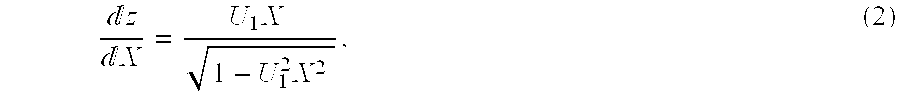
3 is defined by tool radius, r, according to the mathematical expression: z = U ( X - x 1 - l ) 2 1 + 1 - U 2 ( X - x 1 - l ) 2 + C 2 , ( 5 )
Figure US06596025-20030722-M00005
and its derivative: z X = U ( X - x 1 - l ) 1 + 1 - U 2 ( X - x 1 - l ) 2 , ( 6 )
Figure US06596025-20030722-M00006
where U = 1 r
Figure US06596025-20030722-M00007
 is the surface curvature
The Z coordinate at transition zone surface point 4 is preferably selected to have the same z value as at surface point 3. Width, l′, of a surface region 126 between points 3 and 4 is preferably equal to about 0.10 times width, l, and provides a smooth continuity of transition zone 94 to second imaging zone 92.
Mathematical format of surface region 126 is the same as that of surface region 122 between surface points 1 and 2 and is given by the following expression:.
z=A 3(X−x 1 −l)3 +B 3(X−x 1 −l)2 +C 3(X−x 1 −l)+D 3,  (7)
and its derivative: z X = 3 A 3 ( X - x 1 - l ) 2 + 2 B 3 ( X - x 1 - l ) + C 3 ( 8 )
Figure US06596025-20030722-M00008
Second transition zone 92 of radius, r2, beyond transition surface point 4 is defined by the following mathematical expression: z = U 2 X 2 1 + 1 - U 2 2 X 2 + C 4 , ( 9 )
Figure US06596025-20030722-M00009
and its derivative: z X = U 2 X 1 - U 2 2 X 2 , ( 10 )
Figure US06596025-20030722-M00010
where U 2 = 1 r 2
Figure US06596025-20030722-M00011
 is surface curvature
All coefficients A1, B1, C1, D1, C2, A3, B3, C3, D3 and C4 defining transition zone equations are calculated by a standard algebraic procedure for continuous border conditions between first imaging zone 90, each transition zone surface region and second imaging zone 92, that is, equal values for z and dz/dX at each border between adjacent surface regions, and also using surface parameters l, l′, h, r, r1, and r2.
FIG. 9, which is similar to FIG. 1, depicts a bundle of parallel light rays 112 impinging on anterior surface 114 of optic 82 at angle, α. Light rays 112 are refracted, in accordance with Snell's Law, as they enter, pass through and exit optic 82. However, because of the continuously variable curvature of transition zone surface 110 (FIG. 8), the light exits optic 82 as diverging rays 112 a, rather than parallel ays as shown for rays 20 a of the prior art Fresnel lens optic 24 depicted in FIG. 1. (Viewed image light rays are not shown to avoid confusion.)
As depicted in FIG. 10, which corresponds to FIG. 2, diverging light rays 112 a refracted from transition zone surface 110 of optic 82 impinge on a region 115 of retina 48 (shown in broken lines) of representative eye 30 to cause only a very diffused glare pattern 116 (indicated by dots). The result is that indirect glare in an individual's eye is greatly reduced by the non-abrupt, continuously variable curvature of transition zone surface 110, as compared to the indirect glare in an eye caused by flat surface 38 of abrupt Fresnel zone steps 40 of the same height.
FIG. 11 (which corresponds generally to FIGS. 8 and 9), depicts light rays 112 a impinging perpendicularly onto optic anterior surface 114. Due to the particular shape of continuously variably curved transition zone surface 110, as described relative to FIG. 8, light rays 112 a′ are redirected at surface 110 out of the image by internal reflection.
Although a ray 112 a″ is depicted in FIG. 11 as refracted from surface 110 in a diverging manner that could cause some image glare, the glare is nevertheless substantially less than the direct glare caused by sharp corners 52 and 54 of Fresnel zone step 38 (FIG. 3) and other Fresnel zone steps of the same height.
The result of transition zone 94 having the continuously variable curved surface 110 described above, is that optic 82 of IOL 80 provided substantially less glare than sharp, flat Fresnel zone step(s) 38.
It is, of course, to be understood that the continuously variable curvature applied to surface 110 of transistion zone 94 of optic 82 can also be applied to surface 110 a of transition zone 94 a of optic 82 a (FIG. 7) with like glare reduction properties.
FIGS. 12 and 13 depict, in extremely enlarged representations, variation transition zone surface curvatures that although providing somewhat less glare reduction than the continually variable curvature described above for surface 110 of transition zone 94 of optic 82 nevertheless are within the scope of the present invention.
There is thus depicted in FIG. 12 a transition zone 94 b between respective first and second imaging zones 90 b and 92 b of an optic 82 b. As shown, imaging zones 90 b and 92 b may be identical to imaging zones 90 and 92 described above. Surface 110 b of transition zone 94 b is variably curved, but is not continuously variably curved as described above for transition zone surface 110, having, as an example, a discontinuity at a point 130. The variably curved region of transition zone surface 110 b may be developed in a manner analogous to the above-described manner of developing transition zone surface 110 (FIG. 8)
A principal effect of variably curved transition zone surface 110 b is that some direct glare may be caused by light diffraction at discontinuity point 130 in the manner depicted in FIGS. 3 and 4 for known Fresnel zone step 40.
There is depicted in FIG. 1 a transition zone 94 c between respective first and second imaging zones 90 c and 92 c of an optic 82 c. As shown, imaging zones 90 c and 92 c may be identical to imaging zones 90 and 92 described above. Surface 110 c of transition zone 94 c is shown continuously curved, but not continuously variably curved as described above for transition zone surface 110, having, as an example, a central region 132 of non-variable curvature a discontinuity at a point 130. The variably curved regions of transition zone surface 110 c may be developed in a manner analogous to the above-described manner of developing transition zone surface 110 (FIG. 8)
A principal effect of continuously curved transition zone surface 110 c is that some indirect glare may be caused by light refraction from region 132 of surface 110 c in the manner depicted in FIGS. 1 and 2 for known Fresnel zone step 40.
Thus it can be seen from the foregoing that a narrow profile intraocular lens with glare reducing characteristics is provided.
Although there has been described above a narrow profile, monofocal intraocular lens with glare reduction and variations thereof for implant in a narrow space, particularly in the anterior chamber, of a patient's eye, in accordance with the present in mention for purposes of illustrating the manner in which the present invention may be used to advantage, it is to be understood that the invention is not limited thereto. Consequently, any and all variations and equivalent arrangements that may occur to those skilled in the applicable art are to be considered to be within the scope and spirit of the invention as set forth in the claims, which are appended hereto as part of this application.

Claims (16)

What is claimed is:
1. A narrow profile, glare reducing, phakic anterior chamber intraocular lens comprising:
a. an optic having an anterior surface and a posterior surface and an optical axis, only said posterior surface being formed having adjacent first and second peri-axial imaging zones, said posterior surface being monofocal and refractive;
b. a transition zone between paid first and second peri-axial imaging zones, said transition zone having a height of at least about 0.10 mm and having a surface of continuous curvature without any abrupt change in said surface curvature shaped to minimize direct glare in an individual's eye in which said intraocular lens is implanted by causing internal reflection of light coming from a centrally located source of light within a substantial width of said transition zone; and
c. a positioning means joined to said optic for positioning said optic in the anterior chamber of said eye with said optical axis of the optic generally aligned with the optical axis of the eye.
2. The narrow profile, glare reducing, phakic anterior chamber intraocular lens as claimed in claim 1, wherein said transition zone surface has a continuously variable curvature shaped to reduce both indirect and direct glare.
3. The narrow profile, glare reducing, phakic anterior chamber intraocular lens as claimed in claim 1, wherein said first peri-axial imaging zone is centered at the optical axis of the optic.
4. The narrow profile, glare reducing, phakic anterior chamber intraocular lens as claimed in claim 1, wherein said first peri-axial imaging zone is circular in shape, having a diameter between about 4.3 mm and about 4.5 mm and wherein said second peri-axial zone is circular in shape, having a diameter between about 5.5 mm and about 7.5 mm.
5. The narrow profile, glare reducing, phakic anterior chamber intraocular lens as claimed in claim 4, wherein said second peri-axial imaging zone is formed in annular shape around said first peri-axial imaging zone.
6. The narrow profile, glare reducing, phakic anterior chamber intraocular lens as claimed in claim 1, wherein said optic has a maximum thickness at any point that is between about 0.30 mm and about 0.40 mm.
7. The narrow profile, glare reducing, phakic anterior chamber intraocular lens as claimed in claim 1, wherein said optical power is outside a diopter range of about −5 to about +5.
8. The narrow profile, glare reducing, phakic anteriop chamber intraocular lens as claimed in claim 1, wherein the height of said transition zone is between about 0.10 mm and about 0.40 mm.
9. The narrow profile, glare reducing, phakic anterior chamber intraocular lens as claimed in claim 1, wherein said transition zone has a width between about 0.15 mm and about 0.30 mm.
10. A narrow profile, glare reducing, phakic anterior chamber intraocular lens comprising:
a. an optic having an anterior surface and a posterior surface and an optical axis, one of said anterior and posterior surfaces being formed having adjacent first and second peri-axial imaging zones, said posterior surface with peri-axial imaging zones being monofocal and refractive;
b. a transition zone between said first and second peri-axial imaging zones, said transition zone having height of at least about 0.10 mm and having a surface of continuously variable curvature shaped to minimize indirect glare, created by a peripherally located source of light within a substantial width of said transition zone, in an individual's eye in which the intraocular lens is implanted; and
c. a positioning means joined to said optic for positioning said optic lens in the anterior chamber of said eye with said optical axis of the optic generally aligned with the optical axis of the eye.
11. The narrow profile, glare reducing, phakic anterior chamber intraocular lens as claimed in claim 10, wherein said first peri-axial imaging zone is centered on the optical axis of the optic and has a diameter between about 4.3 mm and about 4.5 mm and wherein said second peri-axial imaging zone is formed in annular shape around said first peri-axial imaging zone.
12. The narrow profile, glare reducing, phakic anterior chamber intraocular lens as claimed in claim 10, wherein said optic has a maximum thickness at any point no greater than about 0.40 mm.
13. The narrow profile, glare reducing, phakic anterior chamber intraocular lens as claimed in claim 10, wherein said first peri-axial imaging zone is recessed in said optic relative to said second peri-axial imaging zone.
14. The narrow profile, glare reducing, phakic anterior chamber intraocular lens as claimed in claim 10, wherein said second peri-axial imaging zone is recessed in said optic relative to said first peri-axial imaging zone.
15. The narrow profile, glare reducing, phakic anterior chamber intraocular lens as claimed in claim 10, wherein said optical power is outside a diopter range of about −5 to about +5.
16. The narrow profile, glare reducing, phakic anterior chamber intraocular lens as claimed in claim 10, wherein the height of said transition zone is between about 0.10 mm and about 0.40 mm and wherein said transition zone has a width of between about 0.15 mm and about 0.03 mm.
US09/809,152 2001-03-15 2001-03-15 Narrow profile intraocular lens Expired - Fee Related US6596025B2 (en)

Priority Applications (4)

Application Number Priority Date Filing Date Title
US09/809,152 US6596025B2 (en) 2001-03-15 2001-03-15 Narrow profile intraocular lens
PCT/US2002/002712 WO2002074210A2 (en) 2001-03-15 2002-01-29 Narrow profile intraocular lens
EP02714803A EP1370199A4 (en) 2001-03-15 2002-01-29 Narrow profile intraocular lens
US10/444,896 US7204849B2 (en) 2001-03-15 2003-05-24 Narrow profile intraocular lens

Applications Claiming Priority (1)

Application Number Priority Date Filing Date Title
US09/809,152 US6596025B2 (en) 2001-03-15 2001-03-15 Narrow profile intraocular lens

Related Child Applications (1)

Application Number Title Priority Date Filing Date
US10/444,896 Continuation-In-Part US7204849B2 (en) 2001-03-15 2003-05-24 Narrow profile intraocular lens

Publications (2)

Publication Number Publication Date
US20020161435A1 US20020161435A1 (en) 2002-10-31
US6596025B2 true US6596025B2 (en) 2003-07-22

Family

ID=25200665

Family Applications (1)

Application Number Title Priority Date Filing Date
US09/809,152 Expired - Fee Related US6596025B2 (en) 2001-03-15 2001-03-15 Narrow profile intraocular lens

Country Status (3)

Country Link
US (1) US6596025B2 (en)
EP (1) EP1370199A4 (en)
WO (1) WO2002074210A2 (en)

Cited By (29)

* Cited by examiner, † Cited by third party
Publication number Priority date Publication date Assignee Title
US20050060031A1 (en) * 2003-09-12 2005-03-17 Coroneo Minas Theodore Treatment of photic disturbances in the eye
US20050125056A1 (en) * 2003-12-09 2005-06-09 Jim Deacon Foldable intraocular lens and method of making
WO2004107020A3 (en) * 2003-05-24 2005-08-11 Valdemar Portney Narrow profile intraocular lens
US20060276892A1 (en) * 2002-07-30 2006-12-07 Peter Toop Intraocular lens with one or more compressible haptics
US7381221B2 (en) 2002-11-08 2008-06-03 Advanced Medical Optics, Inc. Multi-zonal monofocal intraocular lens for correcting optical aberrations
US20090088842A1 (en) * 2007-09-27 2009-04-02 Drew Morgan Intraocular Lens
US7615073B2 (en) 2003-12-09 2009-11-10 Advanced Medical Optics, Inc. Foldable intraocular lens and method of making
US20100094262A1 (en) * 2008-10-10 2010-04-15 Ashok Burton Tripathi Real-time surgical reference indicium apparatus and methods for surgical applications
US20100217278A1 (en) * 2009-02-20 2010-08-26 Ashok Burton Tripathi Real-time surgical reference indicium apparatus and methods for intraocular lens implantation
US20110092984A1 (en) * 2009-10-20 2011-04-21 Ashok Burton Tripathi Real-time Surgical Reference Indicium Apparatus and Methods for Astigmatism Correction
US20110160578A1 (en) * 2008-10-10 2011-06-30 Ashok Burton Tripathi Real-time surgical reference guides and methods for surgical applications
US20110213342A1 (en) * 2010-02-26 2011-09-01 Ashok Burton Tripathi Real-time Virtual Indicium Apparatus and Methods for Guiding an Implant into an Eye
US8216307B2 (en) 2008-12-19 2012-07-10 Novartis Ag Radially segmented apodized diffractive multifocal design for ocular implant
US9195074B2 (en) 2012-04-05 2015-11-24 Brien Holden Vision Institute Lenses, devices and methods for ocular refractive error
US9201250B2 (en) 2012-10-17 2015-12-01 Brien Holden Vision Institute Lenses, devices, methods and systems for refractive error
US9220590B2 (en) 2010-06-10 2015-12-29 Z Lens, Llc Accommodative intraocular lens and method of improving accommodation
US9364318B2 (en) 2012-05-10 2016-06-14 Z Lens, Llc Accommodative-disaccommodative intraocular lens
US9541773B2 (en) 2012-10-17 2017-01-10 Brien Holden Vision Institute Lenses, devices, methods and systems for refractive error
US9552660B2 (en) 2012-08-30 2017-01-24 Truevision Systems, Inc. Imaging system and methods displaying a fused multidimensional reconstructed image
US10028825B2 (en) 2016-02-09 2018-07-24 Amo Groningen B.V. Progressive power intraocular lens, and methods of use and manufacture
US10299880B2 (en) 2017-04-24 2019-05-28 Truevision Systems, Inc. Stereoscopic visualization camera and platform
US10398598B2 (en) 2008-04-04 2019-09-03 Truevision Systems, Inc. Apparatus and methods for performing enhanced visually directed procedures under low ambient light conditions
US10512535B2 (en) 2016-08-24 2019-12-24 Z Lens, Llc Dual mode accommodative-disaccomodative intraocular lens
US10917543B2 (en) 2017-04-24 2021-02-09 Alcon Inc. Stereoscopic visualization camera and integrated robotics platform
US11083537B2 (en) 2017-04-24 2021-08-10 Alcon Inc. Stereoscopic camera with fluorescence visualization
US11083566B2 (en) 2016-02-29 2021-08-10 Alcon Inc. Ophthalmic lens having an extended depth of focus
US11452595B2 (en) 2007-08-27 2022-09-27 Amo Groningen B.V. Multizonal lens with enhanced performance
US11506914B2 (en) 2010-12-01 2022-11-22 Amo Groningen B.V. Multifocal lens having an optical add power progression, and a system and method of providing same
US11886046B2 (en) 2019-12-30 2024-01-30 Amo Groningen B.V. Multi-region refractive lenses for vision treatment

Families Citing this family (35)

* Cited by examiner, † Cited by third party
Publication number Priority date Publication date Assignee Title
US20030060878A1 (en) * 2001-08-31 2003-03-27 Shadduck John H. Intraocular lens system and method for power adjustment
US8048155B2 (en) 2002-02-02 2011-11-01 Powervision, Inc. Intraocular implant devices
US10835373B2 (en) 2002-12-12 2020-11-17 Alcon Inc. Accommodating intraocular lenses and methods of use
US8361145B2 (en) 2002-12-12 2013-01-29 Powervision, Inc. Accommodating intraocular lens system having circumferential haptic support and method
US8328869B2 (en) 2002-12-12 2012-12-11 Powervision, Inc. Accommodating intraocular lenses and methods of use
US7217288B2 (en) 2002-12-12 2007-05-15 Powervision, Inc. Accommodating intraocular lens having peripherally actuated deflectable surface and method
EP1599748A4 (en) 2003-03-06 2007-10-24 John H Shadduck Adaptive optic lens and method of making
US6951391B2 (en) * 2003-06-16 2005-10-04 Apollo Optical Systems Llc Bifocal multiorder diffractive lenses for vision correction
US7025456B2 (en) 2004-08-20 2006-04-11 Apollo Optical Systems, Llc Diffractive lenses for vision correction
US7156516B2 (en) 2004-08-20 2007-01-02 Apollo Optical Systems Llc Diffractive lenses for vision correction
US9872763B2 (en) 2004-10-22 2018-01-23 Powervision, Inc. Accommodating intraocular lenses
CN101678149B (en) 2007-02-21 2013-07-17 力景公司 Polymeric materials suitable for ophthalmic devices and methods of manufacture
US20080269889A1 (en) * 2007-04-30 2008-10-30 Simpson Michael J Haptic Junction Designs to Reduce Negative Dysphotopsia
EP2671541B1 (en) 2007-07-23 2019-04-17 PowerVision, Inc. Accommodating intraocular lenses
US8668734B2 (en) 2010-07-09 2014-03-11 Powervision, Inc. Intraocular lens delivery devices and methods of use
JP5752415B2 (en) 2007-07-23 2015-07-22 パワーヴィジョン・インコーポレーテッド Correction of the refractive power of the lens after implantation
US8968396B2 (en) 2007-07-23 2015-03-03 Powervision, Inc. Intraocular lens delivery systems and methods of use
US9610155B2 (en) 2008-07-23 2017-04-04 Powervision, Inc. Intraocular lens loading systems and methods of use
CA2696450C (en) 2007-07-23 2016-02-16 Terah Whiting Smiley Lens delivery system
US8314927B2 (en) * 2007-07-23 2012-11-20 Powervision, Inc. Systems and methods for testing intraocular lenses
US10299913B2 (en) 2009-01-09 2019-05-28 Powervision, Inc. Accommodating intraocular lenses and methods of use
WO2011026068A2 (en) * 2009-08-31 2011-03-03 Powervision, Inc. Lens capsule size estimation
US8900298B2 (en) 2010-02-23 2014-12-02 Powervision, Inc. Fluid for accommodating intraocular lenses
CA2819451A1 (en) * 2010-11-30 2012-06-07 Amo Groningen B.V. Method for designing, evaluating and optimizing ophthalmic lenses and laser vision correction
NL2006307C2 (en) * 2011-02-28 2012-08-29 Oculentis B V Ophthalmic lens having enhanced optical blending zone.
US10433949B2 (en) 2011-11-08 2019-10-08 Powervision, Inc. Accommodating intraocular lenses
FR2985900A1 (en) * 2012-01-24 2013-07-26 Frederic Hehn IMPROVED INTRAOCULAR LENS AND METHOD FOR MANUFACTURING THE SAME
EP2967842B1 (en) 2013-03-15 2020-11-04 Alcon Inc. Method of reconfiguring an intraocular lens for delivery to a delivery device
EP3370647B8 (en) 2015-11-06 2021-06-30 Alcon Inc. Accommodating intraocular lenses and methods of manufacturing
WO2018078439A2 (en) 2016-10-25 2018-05-03 Amo Groningen B.V. Realistic eye models to design and evaluate intraocular lenses for a large field of view
US10739227B2 (en) 2017-03-23 2020-08-11 Johnson & Johnson Surgical Vision, Inc. Methods and systems for measuring image quality
CA3082053A1 (en) 2017-11-30 2019-06-06 Amo Groningen B.V. Intraocular lenses that improve post-surgical spectacle independent and methods of manufacturing thereof
EP3749941A1 (en) 2018-02-08 2020-12-16 AMO Groningen B.V. Wavefront based characterization of lens surfaces based on reflections
EP3749942A1 (en) 2018-02-08 2020-12-16 AMO Groningen B.V. Multi-wavelength wavefront system and method for measuring diffractive lenses
EP4041131A4 (en) 2019-10-04 2023-11-15 Alcon Inc. Adjustable intraocular lenses and methods of post-operatively adjusting intraocular lenses

Citations (27)

* Cited by examiner, † Cited by third party
Publication number Priority date Publication date Assignee Title
US3004470A (en) * 1956-07-28 1961-10-17 Zeiss Ikon A G Stuttgart Multiple focal length lens
US4340283A (en) 1978-12-18 1982-07-20 Cohen Allen L Phase shift multifocal zone plate
US4561736A (en) * 1982-08-07 1985-12-31 Carl-Zeiss-Stiftung Eyeglass lenses for persons suffering from severe ametropia
US4580882A (en) * 1983-04-21 1986-04-08 Benjamin Nuchman Continuously variable contact lens
US4637697A (en) 1982-10-27 1987-01-20 Pilkington P.E. Limited Multifocal contact lenses utilizing diffraction and refraction
US4673406A (en) 1984-10-29 1987-06-16 Inprohold Establishment One-piece implantation lens
US4703405A (en) * 1986-07-17 1987-10-27 Ian Lewin Glare reducing lens
US4787903A (en) 1985-07-24 1988-11-29 Grendahl Dennis T Intraocular lens
US4846833A (en) 1988-05-25 1989-07-11 Cumming J S Sealed fresnel intraocular lens
US4861140A (en) * 1988-01-13 1989-08-29 Eastman Kodak Company Method of making a thin lens
US4881805A (en) * 1987-11-12 1989-11-21 Cohen Allen L Progressive intensity phase bifocal
US4995715A (en) * 1988-07-20 1991-02-26 Cohen Allen L Diffractive multifocal optical device
US5054905A (en) 1987-11-12 1991-10-08 Cohen Allen L Progressive intensity phase bifocal
US5056908A (en) * 1987-11-12 1991-10-15 Cohen Allen L Optic zone phase channels
US5120120A (en) * 1990-07-27 1992-06-09 Cohen Allen L Multifocal optical device with spurious order suppression and method for manufacture of same
US5121980A (en) * 1989-04-19 1992-06-16 Cohen Allen L Small aperture multifocal
US5178636A (en) 1990-05-14 1993-01-12 Iolab Corporation Tuned fresnel lens for multifocal intraocular applications including small incision surgeries
US5201763A (en) * 1992-02-28 1993-04-13 Allergan, Inc. Thin intraocular lens
US5260727A (en) * 1990-10-22 1993-11-09 Oksman Henry C Wide depth of focus intraocular and contact lenses
US5476513A (en) * 1992-02-28 1995-12-19 Allergan, Inc. Intraocular lens
US5507806A (en) * 1994-05-13 1996-04-16 Pharmacia Iovision, Inc. Multi-faceted intraocular lens
US5699142A (en) 1994-09-01 1997-12-16 Alcon Laboratories, Inc. Diffractive multifocal ophthalmic lens
US5755786A (en) * 1992-09-28 1998-05-26 Iolab Corporation Ophthalmic lens with reduced edge glare
US5760871A (en) * 1993-01-06 1998-06-02 Holo-Or Ltd. Diffractive multi-focal lens
US6015435A (en) * 1996-10-24 2000-01-18 International Vision, Inc. Self-centering phakic intraocular lens
US6096077A (en) 1997-08-20 2000-08-01 Thinoptx, Inc. Deformable intraocular corrective lens
US6162249A (en) * 1998-05-29 2000-12-19 Allergan IOI for inhibiting cell growth and reducing glare

Family Cites Families (2)

* Cited by examiner, † Cited by third party
Publication number Priority date Publication date Assignee Title
US5270744A (en) * 1987-06-01 1993-12-14 Valdemar Portney Multifocal ophthalmic lens
US5071207A (en) * 1990-09-25 1991-12-10 The United States Of America As Represented By The United States Department Of Energy Broadband diffractive lens or imaging element

Patent Citations (27)

* Cited by examiner, † Cited by third party
Publication number Priority date Publication date Assignee Title
US3004470A (en) * 1956-07-28 1961-10-17 Zeiss Ikon A G Stuttgart Multiple focal length lens
US4340283A (en) 1978-12-18 1982-07-20 Cohen Allen L Phase shift multifocal zone plate
US4561736A (en) * 1982-08-07 1985-12-31 Carl-Zeiss-Stiftung Eyeglass lenses for persons suffering from severe ametropia
US4637697A (en) 1982-10-27 1987-01-20 Pilkington P.E. Limited Multifocal contact lenses utilizing diffraction and refraction
US4580882A (en) * 1983-04-21 1986-04-08 Benjamin Nuchman Continuously variable contact lens
US4673406A (en) 1984-10-29 1987-06-16 Inprohold Establishment One-piece implantation lens
US4787903A (en) 1985-07-24 1988-11-29 Grendahl Dennis T Intraocular lens
US4703405A (en) * 1986-07-17 1987-10-27 Ian Lewin Glare reducing lens
US5054905A (en) 1987-11-12 1991-10-08 Cohen Allen L Progressive intensity phase bifocal
US4881805A (en) * 1987-11-12 1989-11-21 Cohen Allen L Progressive intensity phase bifocal
US5056908A (en) * 1987-11-12 1991-10-15 Cohen Allen L Optic zone phase channels
US4861140A (en) * 1988-01-13 1989-08-29 Eastman Kodak Company Method of making a thin lens
US4846833A (en) 1988-05-25 1989-07-11 Cumming J S Sealed fresnel intraocular lens
US4995715A (en) * 1988-07-20 1991-02-26 Cohen Allen L Diffractive multifocal optical device
US5121980A (en) * 1989-04-19 1992-06-16 Cohen Allen L Small aperture multifocal
US5178636A (en) 1990-05-14 1993-01-12 Iolab Corporation Tuned fresnel lens for multifocal intraocular applications including small incision surgeries
US5120120A (en) * 1990-07-27 1992-06-09 Cohen Allen L Multifocal optical device with spurious order suppression and method for manufacture of same
US5260727A (en) * 1990-10-22 1993-11-09 Oksman Henry C Wide depth of focus intraocular and contact lenses
US5201763A (en) * 1992-02-28 1993-04-13 Allergan, Inc. Thin intraocular lens
US5476513A (en) * 1992-02-28 1995-12-19 Allergan, Inc. Intraocular lens
US5755786A (en) * 1992-09-28 1998-05-26 Iolab Corporation Ophthalmic lens with reduced edge glare
US5760871A (en) * 1993-01-06 1998-06-02 Holo-Or Ltd. Diffractive multi-focal lens
US5507806A (en) * 1994-05-13 1996-04-16 Pharmacia Iovision, Inc. Multi-faceted intraocular lens
US5699142A (en) 1994-09-01 1997-12-16 Alcon Laboratories, Inc. Diffractive multifocal ophthalmic lens
US6015435A (en) * 1996-10-24 2000-01-18 International Vision, Inc. Self-centering phakic intraocular lens
US6096077A (en) 1997-08-20 2000-08-01 Thinoptx, Inc. Deformable intraocular corrective lens
US6162249A (en) * 1998-05-29 2000-12-19 Allergan IOI for inhibiting cell growth and reducing glare

Non-Patent Citations (1)

* Cited by examiner, † Cited by third party
Title
Analysis of Edge Glare Phenomena in Intraocular Lens Edge design Journal of Refractive Surgery vol 25, 1999, pp. 748-752.

Cited By (72)

* Cited by examiner, † Cited by third party
Publication number Priority date Publication date Assignee Title
US8419791B2 (en) * 2002-07-30 2013-04-16 Rayner Intraocular Lenses Limited Intraocular lens with one or more compressible haptics
US20060276892A1 (en) * 2002-07-30 2006-12-07 Peter Toop Intraocular lens with one or more compressible haptics
US7381221B2 (en) 2002-11-08 2008-06-03 Advanced Medical Optics, Inc. Multi-zonal monofocal intraocular lens for correcting optical aberrations
WO2004107020A3 (en) * 2003-05-24 2005-08-11 Valdemar Portney Narrow profile intraocular lens
EP1631217A2 (en) * 2003-05-24 2006-03-08 Valdemar Portney Narrow profile intraocular lens
EP1631217A4 (en) * 2003-05-24 2010-03-10 Valdemar Portney Narrow profile intraocular lens
US20050060031A1 (en) * 2003-09-12 2005-03-17 Coroneo Minas Theodore Treatment of photic disturbances in the eye
US7217289B2 (en) * 2003-09-12 2007-05-15 Minas Theodore Coronco Treatment of photic disturbances in the eye
US9737396B2 (en) 2003-12-09 2017-08-22 Abbott Medical Optics Inc. Foldable intraocular lens and method of making
US7615073B2 (en) 2003-12-09 2009-11-10 Advanced Medical Optics, Inc. Foldable intraocular lens and method of making
US7621949B2 (en) 2003-12-09 2009-11-24 Advanced Medical Optics, Inc. Foldable intraocular lens and method of making
US20100036490A1 (en) * 2003-12-09 2010-02-11 Abbott Medical Optics Inc. Foldable intraocular lens and method of making
US10420639B2 (en) 2003-12-09 2019-09-24 Johnson & Johnson Surgical Vision, Inc. Foldable intraocular lens and method of making
US20050125056A1 (en) * 2003-12-09 2005-06-09 Jim Deacon Foldable intraocular lens and method of making
US10028822B2 (en) 2003-12-09 2018-07-24 Johnson & Johnson Surgical Vision, Inc. Foldable intraocular lens and method of making
US9259308B2 (en) 2003-12-09 2016-02-16 Abbott Medical Optics Inc. Foldable intraocular lens and method of making
US8382832B2 (en) 2003-12-09 2013-02-26 Abbott Medical Optics Inc. Foldable intraocular lens and method of making
US11452595B2 (en) 2007-08-27 2022-09-27 Amo Groningen B.V. Multizonal lens with enhanced performance
KR101128573B1 (en) 2007-09-27 2012-03-23 알콘 리서치, 리미티드 Intraocular lens
US20090088842A1 (en) * 2007-09-27 2009-04-02 Drew Morgan Intraocular Lens
US10398598B2 (en) 2008-04-04 2019-09-03 Truevision Systems, Inc. Apparatus and methods for performing enhanced visually directed procedures under low ambient light conditions
US20100094262A1 (en) * 2008-10-10 2010-04-15 Ashok Burton Tripathi Real-time surgical reference indicium apparatus and methods for surgical applications
US10117721B2 (en) 2008-10-10 2018-11-06 Truevision Systems, Inc. Real-time surgical reference guides and methods for surgical applications
US9226798B2 (en) * 2008-10-10 2016-01-05 Truevision Systems, Inc. Real-time surgical reference indicium apparatus and methods for surgical applications
US11051884B2 (en) 2008-10-10 2021-07-06 Alcon, Inc. Real-time surgical reference indicium apparatus and methods for surgical applications
US20110160578A1 (en) * 2008-10-10 2011-06-30 Ashok Burton Tripathi Real-time surgical reference guides and methods for surgical applications
US8216307B2 (en) 2008-12-19 2012-07-10 Novartis Ag Radially segmented apodized diffractive multifocal design for ocular implant
US20100217278A1 (en) * 2009-02-20 2010-08-26 Ashok Burton Tripathi Real-time surgical reference indicium apparatus and methods for intraocular lens implantation
US11039901B2 (en) 2009-02-20 2021-06-22 Alcon, Inc. Real-time surgical reference indicium apparatus and methods for intraocular lens implantation
US9173717B2 (en) * 2009-02-20 2015-11-03 Truevision Systems, Inc. Real-time surgical reference indicium apparatus and methods for intraocular lens implantation
US9414961B2 (en) 2009-10-20 2016-08-16 Truevision Systems, Inc. Real-time surgical reference indicium apparatus and methods for astigmatism correction
US20110092984A1 (en) * 2009-10-20 2011-04-21 Ashok Burton Tripathi Real-time Surgical Reference Indicium Apparatus and Methods for Astigmatism Correction
US10368948B2 (en) 2009-10-20 2019-08-06 Truevision Systems, Inc. Real-time surgical reference indicium apparatus and methods for astigmatism correction
US8784443B2 (en) 2009-10-20 2014-07-22 Truevision Systems, Inc. Real-time surgical reference indicium apparatus and methods for astigmatism correction
US20110213342A1 (en) * 2010-02-26 2011-09-01 Ashok Burton Tripathi Real-time Virtual Indicium Apparatus and Methods for Guiding an Implant into an Eye
US9220590B2 (en) 2010-06-10 2015-12-29 Z Lens, Llc Accommodative intraocular lens and method of improving accommodation
US10524900B2 (en) 2010-06-10 2020-01-07 Z Lens, Llc Accommodative intraocular lens and method of improving accommodation
US11506914B2 (en) 2010-12-01 2022-11-22 Amo Groningen B.V. Multifocal lens having an optical add power progression, and a system and method of providing same
US10209535B2 (en) 2012-04-05 2019-02-19 Brien Holden Vision Institute Lenses, devices and methods for ocular refractive error
US9575334B2 (en) 2012-04-05 2017-02-21 Brien Holden Vision Institute Lenses, devices and methods of ocular refractive error
US10203522B2 (en) 2012-04-05 2019-02-12 Brien Holden Vision Institute Lenses, devices, methods and systems for refractive error
US11644688B2 (en) 2012-04-05 2023-05-09 Brien Holden Vision Institute Limited Lenses, devices and methods for ocular refractive error
US11809024B2 (en) 2012-04-05 2023-11-07 Brien Holden Vision Institute Limited Lenses, devices, methods and systems for refractive error
US9535263B2 (en) 2012-04-05 2017-01-03 Brien Holden Vision Institute Lenses, devices, methods and systems for refractive error
US9195074B2 (en) 2012-04-05 2015-11-24 Brien Holden Vision Institute Lenses, devices and methods for ocular refractive error
US10948743B2 (en) 2012-04-05 2021-03-16 Brien Holden Vision Institute Limited Lenses, devices, methods and systems for refractive error
US10466507B2 (en) 2012-04-05 2019-11-05 Brien Holden Vision Institute Limited Lenses, devices and methods for ocular refractive error
US10838235B2 (en) 2012-04-05 2020-11-17 Brien Holden Vision Institute Limited Lenses, devices, and methods for ocular refractive error
US9364318B2 (en) 2012-05-10 2016-06-14 Z Lens, Llc Accommodative-disaccommodative intraocular lens
US10898317B2 (en) 2012-05-10 2021-01-26 Carl Zeiss Meditec Ag Accommodative-disaccommodative intraocular lens
US10019819B2 (en) 2012-08-30 2018-07-10 Truevision Systems, Inc. Imaging system and methods displaying a fused multidimensional reconstructed image
US10740933B2 (en) 2012-08-30 2020-08-11 Alcon Inc. Imaging system and methods displaying a fused multidimensional reconstructed image
US9552660B2 (en) 2012-08-30 2017-01-24 Truevision Systems, Inc. Imaging system and methods displaying a fused multidimensional reconstructed image
US11320672B2 (en) 2012-10-07 2022-05-03 Brien Holden Vision Institute Limited Lenses, devices, systems and methods for refractive error
US9201250B2 (en) 2012-10-17 2015-12-01 Brien Holden Vision Institute Lenses, devices, methods and systems for refractive error
US10520754B2 (en) 2012-10-17 2019-12-31 Brien Holden Vision Institute Limited Lenses, devices, systems and methods for refractive error
US10534198B2 (en) 2012-10-17 2020-01-14 Brien Holden Vision Institute Limited Lenses, devices, methods and systems for refractive error
US11333903B2 (en) 2012-10-17 2022-05-17 Brien Holden Vision Institute Limited Lenses, devices, methods and systems for refractive error
US9541773B2 (en) 2012-10-17 2017-01-10 Brien Holden Vision Institute Lenses, devices, methods and systems for refractive error
US9759930B2 (en) 2012-10-17 2017-09-12 Brien Holden Vision Institute Lenses, devices, systems and methods for refractive error
US10426601B2 (en) 2016-02-09 2019-10-01 Amo Groningen B.V. Progressive power intraocular lens, and methods of use and manufacture
US10028825B2 (en) 2016-02-09 2018-07-24 Amo Groningen B.V. Progressive power intraocular lens, and methods of use and manufacture
US10709550B2 (en) 2016-02-09 2020-07-14 Amo Groningen B.V. Progressive power intraocular lens, and methods of use and manufacture
US11116624B2 (en) 2016-02-09 2021-09-14 Amo Groningen B.V. Progressive power intraocular lens, and methods of use and manufacture
US10624735B2 (en) 2016-02-09 2020-04-21 Amo Groningen B.V. Progressive power intraocular lens, and methods of use and manufacture
US11083566B2 (en) 2016-02-29 2021-08-10 Alcon Inc. Ophthalmic lens having an extended depth of focus
US10512535B2 (en) 2016-08-24 2019-12-24 Z Lens, Llc Dual mode accommodative-disaccomodative intraocular lens
US11083537B2 (en) 2017-04-24 2021-08-10 Alcon Inc. Stereoscopic camera with fluorescence visualization
US11058513B2 (en) 2017-04-24 2021-07-13 Alcon, Inc. Stereoscopic visualization camera and platform
US10299880B2 (en) 2017-04-24 2019-05-28 Truevision Systems, Inc. Stereoscopic visualization camera and platform
US10917543B2 (en) 2017-04-24 2021-02-09 Alcon Inc. Stereoscopic visualization camera and integrated robotics platform
US11886046B2 (en) 2019-12-30 2024-01-30 Amo Groningen B.V. Multi-region refractive lenses for vision treatment

Also Published As

Publication number Publication date
WO2002074210A3 (en) 2003-01-09
EP1370199A4 (en) 2010-04-07
WO2002074210A2 (en) 2002-09-26
US20020161435A1 (en) 2002-10-31
EP1370199A2 (en) 2003-12-17
WO2002074210B1 (en) 2003-03-06

Similar Documents

Publication Publication Date Title
US6596025B2 (en) Narrow profile intraocular lens
US7204849B2 (en) Narrow profile intraocular lens
EP2152202B1 (en) Iol peripheral surface designs to reduce negative dysphotopsia
US6152958A (en) Foldable thin intraocular membrane
US20080269885A1 (en) IOL Peripheral Surface Designs to Reduce Negative Dysphotopsia
US6197057B1 (en) Lens conversion system for teledioptic or difractive configurations
US6800091B2 (en) Method of using a small incision lens
US20080269890A1 (en) Intraocular lens with peripheral region designed to reduce negative dysphotopsia
US6786928B2 (en) Small incision lens
US10561491B2 (en) Reduced glare intraocular lens
US20040230300A1 (en) Accommodating positive and negative intraocular lens system
US20080269882A1 (en) Intraocular lens with asymmetric optics
US20080269883A1 (en) Ocular implant to correct dysphotopsia, glare, halos and dark shadow type phenomena
JP2001500755A (en) Advanced myopic anterior chamber lens with glaring shield
US20080269881A1 (en) Intraocular Lens with Asymmetric Haptics
KR20200100629A (en) Intraocular lens platform with improved scleral force distribution
US20190183636A1 (en) Intraocular lenses having an anterior-biased optical design
US20080269889A1 (en) Haptic Junction Designs to Reduce Negative Dysphotopsia
US20020173845A1 (en) Low surface-glare intraocular lenses
RU2785137C2 (en) Intraocular lenses having optical structure shifted forward
RU2777549C2 (en) Intraocular lens platform with improved distribution of haptic element pressure

Legal Events

Date Code Title Description
AS Assignment

Owner name: OPTHALMIC LENDERS, LLC, TEXAS

Free format text: ASSIGNMENT OF ASSIGNORS INTEREST;ASSIGNOR:O.I.I. INTERNATIONAL, INC.;REEL/FRAME:018061/0295

Effective date: 20060113

FPAY Fee payment

Year of fee payment: 4

AS Assignment

Owner name: WELLS FARGO BANK, NATIONAL ASSOCIATION (ACTING THR

Free format text: SECURITY AGREEMENT;ASSIGNOR:O.I.I. INTERNATIONAL, INC.;REEL/FRAME:020442/0621

Effective date: 20070928

AS Assignment

Owner name: AAREN SCIENTIFIC, INC., CALIFORNIA

Free format text: MERGER;ASSIGNOR:O.I.I. INTERNATIONAL, INC.;REEL/FRAME:022288/0677

Effective date: 20090101

AS Assignment

Owner name: WELLS FARGO BANK, TEXAS

Free format text: FIRST AMENDMENT TO PATENT AND TRADEMARK SECURITY AGREEMENT;ASSIGNOR:AAREN SCIENTIFIC, INC.;REEL/FRAME:023273/0334

Effective date: 20090716

REMI Maintenance fee reminder mailed
LAPS Lapse for failure to pay maintenance fees
STCH Information on status: patent discontinuation

Free format text: PATENT EXPIRED DUE TO NONPAYMENT OF MAINTENANCE FEES UNDER 37 CFR 1.362

FP Lapsed due to failure to pay maintenance fee

Effective date: 20110722