US6587526B1 - Apparatus and method for timing synchronization in OFDM-based wireless systems - Google Patents

Apparatus and method for timing synchronization in OFDM-based wireless systems Download PDF

Info

Publication number
US6587526B1
US6587526B1 US09/416,702 US41670299A US6587526B1 US 6587526 B1 US6587526 B1 US 6587526B1 US 41670299 A US41670299 A US 41670299A US 6587526 B1 US6587526 B1 US 6587526B1
Authority
US
United States
Prior art keywords
prescribed
timing control
control signal
mobile
transmission channel
Prior art date
Legal status (The legal status is an assumption and is not a legal conclusion. Google has not performed a legal analysis and makes no representation as to the accuracy of the status listed.)
Expired - Lifetime
Application number
US09/416,702
Inventor
Junyi Li
Michaela C. Vanderveen
Current Assignee (The listed assignees may be inaccurate. Google has not performed a legal analysis and makes no representation or warranty as to the accuracy of the list.)
Nokia of America Corp
Original Assignee
Lucent Technologies Inc
Priority date (The priority date is an assumption and is not a legal conclusion. Google has not performed a legal analysis and makes no representation as to the accuracy of the date listed.)
Filing date
Publication date
Application filed by Lucent Technologies Inc filed Critical Lucent Technologies Inc
Priority to US09/416,702 priority Critical patent/US6587526B1/en
Assigned to LUCENT TECHNOLOGIES INC. reassignment LUCENT TECHNOLOGIES INC. ASSIGNMENT OF ASSIGNORS INTEREST (SEE DOCUMENT FOR DETAILS). Assignors: LI, JUNYI, VANDERVEEN, MICHAELA C.
Application granted granted Critical
Publication of US6587526B1 publication Critical patent/US6587526B1/en
Anticipated expiration legal-status Critical
Expired - Lifetime legal-status Critical Current

Links

Images

Classifications

    • HELECTRICITY
    • H04ELECTRIC COMMUNICATION TECHNIQUE
    • H04LTRANSMISSION OF DIGITAL INFORMATION, e.g. TELEGRAPHIC COMMUNICATION
    • H04L27/00Modulated-carrier systems
    • H04L27/26Systems using multi-frequency codes
    • H04L27/2601Multicarrier modulation systems
    • H04L27/2626Arrangements specific to the transmitter only
    • H04L27/2646Arrangements specific to the transmitter only using feedback from receiver for adjusting OFDM transmission parameters, e.g. transmission timing or guard interval length
    • HELECTRICITY
    • H04ELECTRIC COMMUNICATION TECHNIQUE
    • H04LTRANSMISSION OF DIGITAL INFORMATION, e.g. TELEGRAPHIC COMMUNICATION
    • H04L1/00Arrangements for detecting or preventing errors in the information received
    • H04L1/02Arrangements for detecting or preventing errors in the information received by diversity reception
    • H04L1/04Arrangements for detecting or preventing errors in the information received by diversity reception using frequency diversity
    • HELECTRICITY
    • H04ELECTRIC COMMUNICATION TECHNIQUE
    • H04LTRANSMISSION OF DIGITAL INFORMATION, e.g. TELEGRAPHIC COMMUNICATION
    • H04L1/00Arrangements for detecting or preventing errors in the information received
    • H04L1/02Arrangements for detecting or preventing errors in the information received by diversity reception
    • H04L1/06Arrangements for detecting or preventing errors in the information received by diversity reception using space diversity
    • HELECTRICITY
    • H04ELECTRIC COMMUNICATION TECHNIQUE
    • H04LTRANSMISSION OF DIGITAL INFORMATION, e.g. TELEGRAPHIC COMMUNICATION
    • H04L27/00Modulated-carrier systems
    • H04L27/26Systems using multi-frequency codes
    • H04L27/2601Multicarrier modulation systems
    • H04L27/2647Arrangements specific to the receiver only
    • H04L27/2655Synchronisation arrangements

Definitions

  • This invention relates to timing synchronization and, more particularly, to timing synchronization in wireless communications systems.
  • OFDM orthogonal frequency division multiplexing
  • a plurality of frequency multiplexed relatively narrow band signals are employed to form a wide band, “high” speed radio transmission link.
  • timing synchronization is required to position the signal in an optimum sampling window and to ensure proper alignment of the phases of the plurality of narrow band signals.
  • it is required to obtain a timing adjustment signal that is employed to adjust timing in order to obtain the properly alignment.
  • this is realized by employing a rotational invariance arrangement or technique that utilizes either spectral, and/or temporal, and/or spatial diversity present in the wireless system to generate a single prescribed parameter of the mobile signal transmission channel.
  • the single prescribed signal transmission channel parameter is obtained by forcing the rotational invariance arrangement or technique to yield the single largest eigenvector from a prescribed relationship of signal data vectors of the signal transmission channel.
  • the prescribed parameter of the signal transmission channel is the delay that is substantially constant over the diversity, while the gain of each signal transmission channel path may vary.
  • the estimated signal transmission channel delay is advantageously employed in a mobile station to adjust the timing alignment of the mobile signal being transmitted over the channel to the base station, thereby ensuring proper positioning of the transmitted mobile signal in the optimum sampling window at the base station.
  • FIG. 1 shows, in simplified block diagram form, details of the timing synchronization portion of a wireless system base station including an embodiment of the invention
  • FIG. 2 shows, in simplified block diagram form, details of the timing synchronization portion of a wireless system mobile station useful in describing an embodiment of the invention
  • FIG. 3 shows, in simplified block diagram form, details of the delay estimation unit of FIG. 1 including an embodiment of the invention.
  • FIG. 4 is a flow chart illustrating the steps of the inventive delay estimation process employed in the estimate processing unit of FIG. 3 .
  • a mobile station transmits a plurality of (pure) single frequency tones, i.e., carrier frequencies, for a prescribed interval to a base station. Then, the base station determines where the multipath profile is located, with the ultimate goal being the placement of the cyclic prefix. To this end, the base station needs to inform each of the mobile users a time interval by which to advance or delay transmission.
  • ⁇ overscore ( ⁇ ) ⁇ is analogous to the cyclic prefix, and in this instance is in the order of, for example, 100 ⁇ s, so that it covers propagation delays for all mobile users regardless of their distance to the serving base station. It is assumed that the signals from mobile users to be timing controlled arrive at the serving base station between time ⁇ overscore ( ⁇ ) ⁇ /2 and ⁇ overscore ( ⁇ ) ⁇ /2, where time “0”is defined arbitrarily as the instance the sampling window starts.
  • This relatively large cyclic prefix ⁇ overscore ( ⁇ ) ⁇ , as well as the multiple tone transmission, are what distinguish the timing control from ordinary data transfer.
  • the signal transmission channels are assumed to have multiple attenuated and delayed paths.
  • x i 1 T ⁇ ⁇ 0 T ⁇ r ⁇ ( t ) ⁇ ⁇ - j2 ⁇ ⁇ ⁇ f i ⁇ t ⁇ ⁇ t ⁇ ⁇ n ⁇ ⁇ n ⁇ ⁇ - j2 ⁇ ⁇ ⁇ f i ⁇ ⁇ n + w i , ( 3 )
  • the wireless system has L diversity antennas.
  • the base station has L diversity avenues, i.e., channels. Practical values of L are small. Indeed, most current wireless systems employ two diversity antennas at each base station sector, i.e., cell. Then, L sets of data vectors x are obtained according to equation (6) above.
  • the purpose of diversity antennas is to obtain substantially uncorrelated signal transmission channels. We have recognized that what has changed in the signal transmission channel is the path gains and not the path delays. Stated another way, the path delay is substantially constant over diversity, while the gain of each channel path may vary.
  • Spectral (frequency) and temporal (time) diversity may also be exploited.
  • L sets of tones are transmitted over the mobile signal transmission channel.
  • the sets of tones should be separated in frequency by greater than the coherence bandwidth of the mobile signal transmission channel.
  • the above noted set of tones is transmitted over the mobile signal transmission channel during L timing control intervals separated in time by greater than the coherence time of the mobile signal transmission channel.
  • combinations of diversity are possible, for example, when the mobile user transmits one set of tones during a timing control interval, then another set of tones in a timing control interval some time later, and the received signal is captured during each instance by two diversity antennas.
  • a requirement is that the transmission path delays stay substantially constant during the two timing control intervals.
  • FIG. 1 shows, in simplified block diagram form, details of the timing synchronization portion of a wireless system base station including an embodiment of the invention.
  • a received signal from a user mobile station 200 (FIG. 2 ), as indicated in Equation (2) and described above, is supplied to input terminal 101 and, then, to synchronization signal extraction unit 102 .
  • Unit 102 includes an optimum sampling window, as described above, and extracts the timing synchronization signal in well known fashion.
  • the extracted signal is down-converted to yield a continuous time down converted and windowed signal.
  • This signal is supplied to delay estimation unit 103 .
  • the received signal may be modulated by synchronization symbols assigned to the particular user mobile station. In such an instance, it is necessary to remove the synchronization symbols from the received signal.
  • the assigned symbols for the particular received signal are supplied from synchronization symbol database 104 to delay estimation unit 103 where they are used to remove the synchronization symbols from the received signal, as described below in conjunction with FIG. 3 .
  • Delay estimation unit 103 generates a delay estimate ⁇ that is supplied as an output as signal timing control parameter ⁇ circumflex over ( ⁇ ) ⁇ that, in turn, is supplied to format of timing error feedback signal unit 105 . It is noted that the estimated delay parameter of the signal transmission channel can be either positive or negative.
  • unit 105 formats the signal, including the synchronization timing control signal, into a timing error feedback signal to be transmitted to the particular mobile user station 200 .
  • the timing error feedback signal indicates the time interval that the transmit symbol clock has to be either advanced or delayed.
  • the formatted signal perhaps in the form of a message is supplied as an output via output terminal 106 .
  • FIG. 2 shows, in simplified block diagram form, details of the timing synchronization portion of a wireless system mobile user station 200 useful in describing an embodiment of the invention.
  • a received timing error feedback signal from base station 100 is supplied via input terminal 201 to clock offset adjustment unit 202 .
  • Unit 202 extracts the transmit offset value from the received timing error feedback signal in known fashion. In one example, the interval may be in microseconds that the transmit clock has to be advanced or delayed. If the offset value is in a message the interval is typically expressed in time increments.
  • the transmit clock offset is supplied to variable time adjustment unit 203 . Also supplied to variable time adjustment unit 203 is the transmit symbol clock from transmit symbol clock unit 204 .
  • Variable time adjustment unit 203 in response to the transmit clock offset, adjusts the transmit clock accordingly, in well known fashion. As indicated above the transmit clock is advanced or delayed by the transmit offset interval so that the transmitted signal from user mobile user station 200 will be substantially centered in the optimum sampling window in base station 100 .
  • the adjusted transmit symbol clock is supplied to synchronization signal insertion unit 205 where it is used to properly insert the synchronization signal for transmission to the base station in any other current data signal.
  • FIG. 3 shows, in simplified block diagram form, details of the delay estimation unit 103 of FIG. 1 including an embodiment of the invention.
  • the continuous-time and down-converted and windowed signal synchronization signal extraction unit 102 (FIG. 1) is supplied via input terminal 301 to Inverse Fast Fourier Transform (IFFT) unit 302 .
  • Unit 302 yields a set of complex values 303 - 1 through 301 -N, one for each simultaneously received tone or sinusoid. Thus, N tones or sinusoids are received at base station 100 .
  • Complex values 303 - 1 through 303 -N are simultaneously supplied to symbol divide unit 304 .
  • Also supplied to unit 304 are assigned symbols from synchronization symbol database 104 (FIG. 1 ).
  • Each of the complex values 303 - 1 through 303 -N is equal to the product of the frequency response of the signal transmission channel (sampled at the frequency/tone), and the assigned data symbol plus any noise introduced by transmit channel and/or by the transmitter and receiver.
  • Unit 304 removes the assigned symbols by dividing them out of the complex values 303 - 1 through 303 -N.
  • the resulting output from unit 304 are noisy channel frequency response samples 305 - 1 through 305 -N. Note that in some systems pure tones are transmitted and, therefore, there is no need to remove any symbols form the complex values and unit 304 is not necessary.
  • Channel frequency response samples 305 - 1 through 305 -N are supplied 30 to estimate processing unit 306 .
  • Unit 306 may be for example a digital signal processor (DSP).
  • DSP digital signal processor
  • Estimate processing unit 306 utilizes channel frequency response samples 305 - 1 through 305 -N, as described below in FIG. 4, to generate the single timing delay estimate ⁇ circumflex over ( ⁇ ) ⁇ that is supplied as an output via terminal 307 .
  • the mobile station 200 is transmitting other tones shortly after the simultaneously transmitted tones or sinusoids employed above, as part of the same synchronization interval, other tones are also processed in the same fashion as the channel frequency response samples 305 - 1 through 305 -N above, and the aggregate data is supplied concurrently to estimate processing unit 306 .
  • the base station 100 is receiving data simultaneously on two or more antennas, this received data is also processed in a similar fashion as described above and, then, supplied to estimate processing unit 306 .
  • FIG. 4 is a flow chart illustrating the steps of the inventive delay estimation process employed in the estimate processing unit 306 of FIG. 3 .
  • the coherence bandwidth is a relatively loosely defined quantity, indicating that the signal transmission channel frequency response is strongly correlated across M contiguous tones, or M ⁇ Hz, where ⁇ is the tone spacing in Hz.
  • the diversity order is the number of such sets of M contiguous tones that are sufficiently decorrelated among them.
  • the signal transmission channel is deemed to be substantially flat in a frequency band containing M contiguous tones
  • obtained from two diversity antennas are two M-long vectors x 1 and x 2 , which are substantially uncorrelated.
  • diversity L 2.
  • not all of the L x i vectors need to be mutually decorrelated or independent in order for the proper operation of estimate processing unit 306 .
  • step 401 the delay estimation process in started in step 401 by inputting the complex scalars 305 - 1 through 305 -N.
  • step 402 causes the complex scalars to be arranged into vectors x I , . . . , X L as described above.
  • Step 404 causes the computation of the eigenvector of matrix R of step 403 corresponding to the single largest eigenvalue, in accordance with the invention. This is realized, for example, by employing the so-called power method. See for example a book authored by G. Golub and C. Van Loan entitled Matrix Computations , The John Hopkins University Press, 1989. The found largest single eigenvector is denoted “b” of R.
  • step 405 vectors b 1 and b 2 are formed. This is realized by extracting the first M ⁇ K entries of vector b and denoting the resulting vector b 1 , and similarly extracting the last M ⁇ K entries of b and denoting the resulting vector b 2 .
  • step 407 causes the delay estimate ⁇ circumflex over ( ⁇ ) ⁇ is obtained. This is realized by dividing the angle of ⁇ by ⁇ 2 ⁇ where ⁇ is the tone spacing.
  • delay estimate ⁇ is supplied as an output as timing control signal ⁇ circumflex over ( ⁇ ) ⁇ .

Abstract

A prescribed signal transmission channel parameter is estimated by employing a unique arrangement and/or method that does not require the estimation of all the signal channel parameters. Specifically, this is realized by employing a rotational invariance arrangement or technique that utilizes either spectral, and/or temporal, and/or spatial diversity present in the wireless system to generate a single prescribed parameter of the mobile signal transmission channel. The single prescribed signal transmission channel parameter is obtained by forcing the rotational invariance arrangement or technique to yield the single largest eigenvector from a prescribed relationship of signal data vectors of the signal transmission channel. In one embodiment of the invention the prescribed parameter of the signal transmission channel is the delay that is substantially constant over the diversity, while the gain of each signal transmission channel path may vary. The estimated signal transmission channel delay is advantageously employed in a mobile station to adjust the timing alignment of the mobile signal being transmitted over the transmission channel to the base station, thereby ensuring proper positioning of the transmitted mobile signal in the optimum sampling window at the base station.

Description

TECHNICAL FIELD
This invention relates to timing synchronization and, more particularly, to timing synchronization in wireless communications systems.
BACKGROUND OF THE INVENTION
Recently, orthogonal frequency division multiplexing (OFDM) has been applied to communications systems and, in particular, to wireless communications systems. In OFDM a plurality of frequency multiplexed relatively narrow band signals are employed to form a wide band, “high” speed radio transmission link. In such an arrangement timing synchronization is required to position the signal in an optimum sampling window and to ensure proper alignment of the phases of the plurality of narrow band signals. To this end, it is required to obtain a timing adjustment signal that is employed to adjust timing in order to obtain the properly alignment.
Indeed, in multiple access systems based on OFDM, it is critical that there be synchronous arrival of mobile user symbols at a base station. If a particular user's arriving symbols are offset in time relative to other synchronized user's arriving symbols, the result is interference to the arriving symbols of all the mobile users.
In prior arrangements, attempts have been made to generate a timing adjustment signal through the estimation of all of the signal transmission channel parameters.
One prior known arrangement for estimating signal parameters is described in U.S. Pat. No. 4,750,147 issued on Jun. 7, 1988 which is commonly referred to as “ESPRIT” (Estimation of Signal Parameters using Rotational Invariance Techniques). The ESPRIT technique is based on maximum likelihood entropy principles, or subspaces, for the estimation of sinusoid signal parameters. As such, ESPRIT cannot be directly applied to estimation of signal parameters in an OFDM system because ESPRIT is directed toward extracting all of the signal transmission channel parameters and there is insufficient data to realize this. Moreover, extracting all the signal transmission channel parameters generally requires a large amount of measurement data, which either is not available or results in significant system overhead. Indeed, in an OFDM system there are just too many parameters for all of them to be uniquely identified as is required in the prior ESPRIT arrangement.
SUMMARY OF THE INVENTION
Problems and limitations of prior known arrangements and techniques for signal transmission channel parameter estimation are overcome by employing a unique arrangement and/or method that does not require the estimation of all the signal transmission channel parameters.
Specifically, this is realized by employing a rotational invariance arrangement or technique that utilizes either spectral, and/or temporal, and/or spatial diversity present in the wireless system to generate a single prescribed parameter of the mobile signal transmission channel.
The single prescribed signal transmission channel parameter is obtained by forcing the rotational invariance arrangement or technique to yield the single largest eigenvector from a prescribed relationship of signal data vectors of the signal transmission channel.
In one embodiment of the invention the prescribed parameter of the signal transmission channel is the delay that is substantially constant over the diversity, while the gain of each signal transmission channel path may vary. The estimated signal transmission channel delay is advantageously employed in a mobile station to adjust the timing alignment of the mobile signal being transmitted over the channel to the base station, thereby ensuring proper positioning of the transmitted mobile signal in the optimum sampling window at the base station.
BRIEF DESCRIPTION OF THE DRAWING
FIG. 1 shows, in simplified block diagram form, details of the timing synchronization portion of a wireless system base station including an embodiment of the invention;
FIG. 2 shows, in simplified block diagram form, details of the timing synchronization portion of a wireless system mobile station useful in describing an embodiment of the invention;
FIG. 3 shows, in simplified block diagram form, details of the delay estimation unit of FIG. 1 including an embodiment of the invention; and
FIG. 4 is a flow chart illustrating the steps of the inventive delay estimation process employed in the estimate processing unit of FIG. 3.
DETAILED DESCRIPTION Theoretical Discussion of Problem Formulation
It is noted that there is possible interference between same cell mobile users that can be avoided. To realize this, it is crucial that all the mobile users' symbol intervals are time-aligned. Indeed, because of multipath signal transmission, this timing control task does not reduce to simply estimating the arrival of a first signal from each of the same cell mobile users. Rather, it is necessary to estimate the time range of the signal transmission channel power-delay profile. The ultimate goal is to correctly place the channel cyclic prefix window, with no significant channel energy outside of it. Simply stated, the channel cyclic prefix window is placed to cover the signal transmission channel impulse response.
To realize timing control, a mobile station transmits a plurality of (pure) single frequency tones, i.e., carrier frequencies, for a prescribed interval to a base station. Then, the base station determines where the multipath profile is located, with the ultimate goal being the placement of the cyclic prefix. To this end, the base station needs to inform each of the mobile users a time interval by which to advance or delay transmission. A prescribed timing control interval, {overscore (τ)}+T, is determined in advance. Note that the center frequency of the ith tone is fi=fc+iΔ, and T is the symbol period, i.e., the period of the frequency tones. The first carrier frequency is fc and the carrier frequencies are spaced apart by Δ=W/N=1/Thz, where W is the total bandwidth available to the system and N is the number of tones. Furthermore, {overscore (τ)} is analogous to the cyclic prefix, and in this instance is in the order of, for example, 100 μs, so that it covers propagation delays for all mobile users regardless of their distance to the serving base station. It is assumed that the signals from mobile users to be timing controlled arrive at the serving base station between time −{overscore (τ)}/2 and {overscore (τ)}/2, where time “0”is defined arbitrarily as the instance the sampling window starts. This relatively large cyclic prefix {overscore (τ)}, as well as the multiple tone transmission, are what distinguish the timing control from ordinary data transfer.
The signal transmission channels are assumed to have multiple attenuated and delayed paths. To clarify, the signal transmission channel, let αn(t), τn(t) be the nth path complex attenuation and delay, respectively. If a mobile user transmits M pure tones, s ( t ) = M i = 1 j2π f i t . ( 1 )
Figure US06587526-20030701-M00001
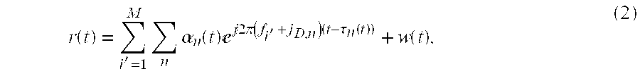
Then, the signal received at the serving base station is r ( t ) = M i = 1 n α n ( t ) j2π ( f i + j D , n ) ( t - τ n ( t ) ) + w ( t ) , ( 2 )
Figure US06587526-20030701-M00002
where −{overscore (τ)}/2≦τn(t)≦{overscore (τ)}/2, and w(t) is the noise and interference, and fD,n the Doppler shift of each path. In the following, for simplicity of notation the time dependency is dropped of αn(t), τn(t) and θn(t).
The windowing and Discrete Fourier Transform (DFT) yield: x i = 1 T 0 T r ( t ) - j2π f i t t n α n - j2π f i τ n + w i , ( 3 )
Figure US06587526-20030701-M00003
where i=1, . . . , M. Note that the approximation results from neglecting the effect of the Doppler shift, and wi is the sampled frequency response of the noise. Since the path attenuation does not vary from tone to tone, as in the case when the total, null-to-null bandwidth of the tones is less than the coherence bandwidth of the signal transmission channel, then x i = n - i τ n α n + w i , ( 4 )
Figure US06587526-20030701-M00004
where i=1, . . . , M and ωi=2πfi. In matrix form, the data satisfies [ x 1 x M ] = [ - i τ 1 - 1 τ 2 - M τ 1 - M τ 2 ] [ α 1 α 2 ] + [ w 1 w 2 ] , ( 5 )
Figure US06587526-20030701-M00005
namely,
x=Ha+w.  (6)
It is assumed that the wireless system has L diversity antennas. For example, the base station has L diversity avenues, i.e., channels. Practical values of L are small. Indeed, most current wireless systems employ two diversity antennas at each base station sector, i.e., cell. Then, L sets of data vectors x are obtained according to equation (6) above. The purpose of diversity antennas is to obtain substantially uncorrelated signal transmission channels. We have recognized that what has changed in the signal transmission channel is the path gains and not the path delays. Stated another way, the path delay is substantially constant over diversity, while the gain of each channel path may vary. Therefore, the ith tone data at the Ith antenna, Xi(l), becomes x i ( l ) = n α n ( l ) - i τ n , ( 7 )
Figure US06587526-20030701-M00006
where i =1, . . . , M, l=1, . . . , L, and αn(l), wi(l) are substantially uncorrelated over diversity. Now since the delay matrix H remains unchanged, then the data model is
x(l)=Ha(l)+w(l),  (8)
where l=1, . . . , L, and α(l), w(l) are substantially uncorrelated over diversity.
The example described above is for spatial diversity. Spectral (frequency) and temporal (time) diversity may also be exploited. In the case of spectral diversity, L sets of tones are transmitted over the mobile signal transmission channel. The sets of tones should be separated in frequency by greater than the coherence bandwidth of the mobile signal transmission channel. To realize temporal diversity, the above noted set of tones is transmitted over the mobile signal transmission channel during L timing control intervals separated in time by greater than the coherence time of the mobile signal transmission channel. Indeed, combinations of diversity are possible, for example, when the mobile user transmits one set of tones during a timing control interval, then another set of tones in a timing control interval some time later, and the received signal is captured during each instance by two diversity antennas. Note that when employing temporal diversity, a requirement is that the transmission path delays stay substantially constant during the two timing control intervals.
Preferred Embodiment(s)
FIG. 1 shows, in simplified block diagram form, details of the timing synchronization portion of a wireless system base station including an embodiment of the invention. Specifically, a received signal from a user mobile station 200 (FIG. 2), as indicated in Equation (2) and described above, is supplied to input terminal 101 and, then, to synchronization signal extraction unit 102. Unit 102 includes an optimum sampling window, as described above, and extracts the timing synchronization signal in well known fashion. The extracted signal is down-converted to yield a continuous time down converted and windowed signal. This signal is supplied to delay estimation unit 103. In certain applications the received signal may be modulated by synchronization symbols assigned to the particular user mobile station. In such an instance, it is necessary to remove the synchronization symbols from the received signal. To this end, the assigned symbols for the particular received signal are supplied from synchronization symbol database 104 to delay estimation unit 103 where they are used to remove the synchronization symbols from the received signal, as described below in conjunction with FIG. 3. Note if or when the mobile user station 200 is transmitting only pure tones, no synchronization symbols are required from database 104. Indeed, in certain applications synchronization symbol database 104 may not be used at all or even included in the implementation. Delay estimation unit 103 generates a delay estimate τ that is supplied as an output as signal timing control parameter {circumflex over (τ)} that, in turn, is supplied to format of timing error feedback signal unit 105. It is noted that the estimated delay parameter of the signal transmission channel can be either positive or negative. When the delay is negative, a timing control signal is generated having a corresponding positive adjustment interval, and when the delay is positive, a timing control signal is generated having a corresponding negative adjustment interval. Then, unit 105 formats the signal, including the synchronization timing control signal, into a timing error feedback signal to be transmitted to the particular mobile user station 200. The timing error feedback signal indicates the time interval that the transmit symbol clock has to be either advanced or delayed. Thereafter, the formatted signal perhaps in the form of a message is supplied as an output via output terminal 106.
FIG. 2 shows, in simplified block diagram form, details of the timing synchronization portion of a wireless system mobile user station 200 useful in describing an embodiment of the invention. A received timing error feedback signal from base station 100 is supplied via input terminal 201 to clock offset adjustment unit 202. Unit 202 extracts the transmit offset value from the received timing error feedback signal in known fashion. In one example, the interval may be in microseconds that the transmit clock has to be advanced or delayed. If the offset value is in a message the interval is typically expressed in time increments. The transmit clock offset is supplied to variable time adjustment unit 203. Also supplied to variable time adjustment unit 203 is the transmit symbol clock from transmit symbol clock unit 204. Variable time adjustment unit 203, in response to the transmit clock offset, adjusts the transmit clock accordingly, in well known fashion. As indicated above the transmit clock is advanced or delayed by the transmit offset interval so that the transmitted signal from user mobile user station 200 will be substantially centered in the optimum sampling window in base station 100. The adjusted transmit symbol clock is supplied to synchronization signal insertion unit 205 where it is used to properly insert the synchronization signal for transmission to the base station in any other current data signal.
FIG. 3 shows, in simplified block diagram form, details of the delay estimation unit 103 of FIG. 1 including an embodiment of the invention. The continuous-time and down-converted and windowed signal synchronization signal extraction unit 102 (FIG. 1) is supplied via input terminal 301 to Inverse Fast Fourier Transform (IFFT) unit 302. Unit 302 yields a set of complex values 303-1 through 301-N, one for each simultaneously received tone or sinusoid. Thus, N tones or sinusoids are received at base station 100. Complex values 303-1 through 303-N are simultaneously supplied to symbol divide unit 304. Also supplied to unit 304 are assigned symbols from synchronization symbol database 104 (FIG. 1). Each of the complex values 303-1 through 303-N is equal to the product of the frequency response of the signal transmission channel (sampled at the frequency/tone), and the assigned data symbol plus any noise introduced by transmit channel and/or by the transmitter and receiver. Unit 304 removes the assigned symbols by dividing them out of the complex values 303-1 through 303-N. The resulting output from unit 304 are noisy channel frequency response samples 305-1 through 305-N. Note that in some systems pure tones are transmitted and, therefore, there is no need to remove any symbols form the complex values and unit 304 is not necessary. Channel frequency response samples 305-1 through 305-N are supplied 30 to estimate processing unit 306. Unit 306 may be for example a digital signal processor (DSP). Estimate processing unit 306 utilizes channel frequency response samples 305-1 through 305-N, as described below in FIG. 4, to generate the single timing delay estimate {circumflex over (τ)} that is supplied as an output via terminal 307. Note that if the mobile station 200 is transmitting other tones shortly after the simultaneously transmitted tones or sinusoids employed above, as part of the same synchronization interval, other tones are also processed in the same fashion as the channel frequency response samples 305-1 through 305-N above, and the aggregate data is supplied concurrently to estimate processing unit 306. Similarly, if the base station 100 is receiving data simultaneously on two or more antennas, this received data is also processed in a similar fashion as described above and, then, supplied to estimate processing unit 306.
FIG. 4 is a flow chart illustrating the steps of the inventive delay estimation process employed in the estimate processing unit 306 of FIG. 3.
Complex values, i.e., channel frequency response samples, 305-1 through 305-N are N complex scalars that are the baseband signal transmission channel estimates. These estimates are grouped according to the coherence bandwidth M of the signal transmission channel and the diversity order such that N=ML. The coherence bandwidth is a relatively loosely defined quantity, indicating that the signal transmission channel frequency response is strongly correlated across M contiguous tones, or MΔHz, where Δ is the tone spacing in Hz. The diversity order is the number of such sets of M contiguous tones that are sufficiently decorrelated among them. As indicated above the diversity can be spatial, i.e., data is obtained from widely separated antennas, temporal, i.e., data is obtained from transmissions at different points in time, or spectral, i.e., data is obtained from transmissions in different parts of the transmission frequency band. Then, each diversity set contains M tones, and can be thought as an M-dimensional vector xi, where i=1, . . . , L and L is the order of diversity, as described above. By way of an example, if the signal transmission channel is deemed to be substantially flat in a frequency band containing M contiguous tones, then obtained from two diversity antennas are two M-long vectors x1and x2, which are substantially uncorrelated. Note that diversity L=2. Further, note that not all of the L xi vectors need to be mutually decorrelated or independent in order for the proper operation of estimate processing unit 306.
Referring now to the flowchart of FIG. 4, the delay estimation process in started in step 401 by inputting the complex scalars 305-1 through 305-N. The, step 402 causes the complex scalars to be arranged into vectors xI, . . . , XL as described above. Thereafter, step 403 forms the autocorrelation matrix R = 1 L i = 1 L x i x i * ,
Figure US06587526-20030701-M00007
where “*” indicates the complex conjugate. Step 404 causes the computation of the eigenvector of matrix R of step 403 corresponding to the single largest eigenvalue, in accordance with the invention. This is realized, for example, by employing the so-called power method. See for example a book authored by G. Golub and C. Van Loan entitled Matrix Computations, The John Hopkins University Press, 1989. The found largest single eigenvector is denoted “b” of R. In step 405, vectors b1 and b2 are formed. This is realized by extracting the first M−K entries of vector b and denoting the resulting vector b1, and similarly extracting the last M−K entries of b and denoting the resulting vector b2. “K” is an implementation dependent overlap parameter, which is an integer chosen to be greater than or equal to “1” and strictly less than M/2. Typically, K is chosen such that K=1. Step 406 causes a complex scalar ψ to be found that exactly or approximately satisfies b1ψ=b2. In one example, this is realized by employing the least squares method or more appropriately the total least squares method also described in the Matrix Computation book noted above. Finally, step 407 causes the delay estimate {circumflex over (τ)} is obtained. This is realized by dividing the angle of ψ by −2πΔwhere Δ is the tone spacing. In this example, the “angle” of a complex number ψ is θ, a number between −π and π, where ψ=re, r is the magnitude of ψ and j={square root over (−1)}. Then, in step 408 delay estimate τ is supplied as an output as timing control signal {circumflex over (τ)}.
The above-described methods and apparatus are, of course, merely illustrative of the principles of the invention. Indeed, numerous other methods or apparatus may be devised by those skilled in the art without departing from the spirit and scope of the invention.

Claims (54)

What is claimed is:
1. Apparatus for use in a wireless communications system for generating a timing control signal comprising:
a receiver for receiving a signal including a plurality of tones from at least one mobile station;
a first prescribed processor supplied with Wd received tones for generating a corresponding plurality of complex scalars of the mobile user transmission channel; and
an estimate processor supplied with said plurality of complex scalars for generating a single prescribed parameter representative of delay characteristics of said mobile user transmission channel and for utilizing said single prescribed parameter representative of delay characteristics in accordance with prescribed criteria to generate said timing control signal,
wherein said timing control signal is to be transmitted to said mobile unit where it ensures proper positioning of a transmitted mobile signal in the optimum sampling window at a base station by being responsive to said timing control signal to controllably delay or advance a transmit symbol clock in said mobile unit.
2. The invention as defined in claim 1 wherein said first prescribed processor includes apparatus for providing a prescribed sampling window through which said received tones are passed through.
3. The invention as defined in claim 1 wherein said first prescribed processor further includes a prescribed transform function unit for generating said plurality of complex scalars.
4. The invention as defined in claim 3 wherein said prescribed transform function is an inverse discrete Fourier transform.
5. The invention as defined in claim 3 wherein said prescribed transform function is an inverse fast Fourier transform.
6. The invention as defined in claim 3 wherein each of said plurality of complex scalars is a channel frequency response sample.
7. The invention as defined in claim 6 wherein said estimate processor further includes apparatus for arranging said channel frequency response samples into a plurality of prescribed vectors.
8. The invention as defined in claim 7 wherein said prescribed vectors are over a prescribed diversity.
9. The invention as defined in claim 8 wherein said diversity is at least two (2).
10. The invention as defined in claim 8 wherein said estimate processor further includes apparatus for obtaining an autocorrelation matrix of said prescribed vectors.
11. The invention as defined in claim 10 wherein said prescribed parameter representation of delay charcteristics is the largest eigenvector of said autocorrelation matrix.
12. The invention as defined in claim 11 wherein said single largest eigenvector is obtained by employing a power method solution of said autocorrelation matrix.
13. The invention as defined in claim 11 wherein said prescribed criteria includes forming a first prescribed vector (b1) and a second prescribed vector (b2) from said single largest eigenvector, finding a prescribed complex scalar (ψ) that satisfies a function b1ψ=b2, finding an angle (θ) of ψ and finding the timing control signal {circumflex over (τ)}, where {circumflex over (τ)}=−θ/2πΔ and Δ is the received tone spacing in Hz.
14. The invention as defined in claim 13 wherein said vector b1 is obtained by extracting the first M−K entries of said single largest eigenvector, and said vector b2 is obtained by extracting the last M−K entries of said single largest eigenvector, where, M is a number of contiguous tones in a diversity set and K is an integer chosen to be greater than or equal to “1” and strictly less than M/2.
15. The invention as defined in claim 13 wherein said complex scalar (ψ) is obtaining by employing a total least squares technique.
16. The invention as defined in claim 14 wherein said timing control signal is a delay estimate.
17. The invention as defined in claim 1 wherein said received tones are modulated by synchronization symbols assigned to said at least one mobile station, and wherein said estimation processor includes apparatus for removing said synchronization symbols from said transmission coefficients.
18. Apparatus for use in adjusting timing in a wireless communication system including a base station and at least one mobile station comprising:
in said base station, a receiver for receiving a signal including a plurality of tones from at least one mobile station,
a first prescribed processor supplied with said received tones for generating a corresponding plurality of complex scalars of the mobile user transmission channel, and
an estimate processor supplied with said plurality of complex scalars for generating a single prescribed parameter representative of delay characteristics of said mobile user transmission channel and for utilizing said single prescribed parameter representative of delay characteristics in accordance with prescribed criteria to generate said timing control signal; and
in said mobile station, an adjustable time transmit symbol clock responsive to said timing control signal received from said base station for controllably delaying or advancing said transmit symbol clock,
wherein proper positioning of a transmitted mobile signal is ensured in the optimum sampling window at a base station by being responsive to said timing control signal to controllably delay or advance said transmit symbol clock.
19. The invention as defined in claim 18 wherein said first prescribed processor further includes a prescribed transform function unit for generating said plurality of complex scalars.
20. The invention as in claim 19 wherein said prescribed prescribed transform function is an inverse discrete Fourier transform.
21. The invention as defined in claim 19 wherein said prescribed transform function is an inverse fast Fourier transform.
22. The invention as defined in claim 19 wherein each of said plurality of complex scalars is a channel frequency response sample.
23. The invention as defined in claim 22 wherein said estimate processor further includes apparatus for arranging said channel frequency response samples into a plurality of prescribed vectors.
24. The invention as defined in claim 23 wherein said prescribed vectors are over a prescribed diversity.
25. The invention as defined in claim 24 herein said diversity is at least two (2).
26. The invention as defined in claim 24 wherein said estimate processor further includes apparatus for obtaining an autocorrelation matrix of said prescribed vectors.
27. The invention as defined in claim 26 wherein said single prescribed parameter representation of delay characteristics is the largest eignvector of said autocorrelation matrix.
28. The invention as defined in claim 27 wherein said single largest eigenvector is obtained by employing a power method solution of said autocorrelation matrix.
29. The invention as defined in claim 27 wherein said prescribed criteria includes forming a first prescribed vector (b1) and a second prescribed vector (b2) from said single largest eigenvector, finding a prescribed complex scalar (ψ) that satisfies a function b1ψ=b2, finding an angle (θ) of ψ and finding the timing control signal {circumflex over (τ)}, where {circumflex over (τ)}=−θ/2πΔ and Δ is the received tone spacing in Hz.
30. The invention as defined in claim 18 wherein said estimation processor includes apparatus for removing said synchronization symbols from said transmission coefficients.
31. Apparatus for use in a wireless communications system for generating a timing control signal comprising:
means for receiving a signal including a plurality of tones from at least one mobile station;
first means supplied with said received tones for generating a corresponding plurality of complex scalars of the mobile user transmission channel; and
second means supplied with said plurality of complex scalars for generating a single prescribed parameter representative of delay characteristics of said mobile user transmission channel and for utilizing said single prescribed parameter representative of delay characteristics in accordance with prescribed criteria to generate said timing control signal,
wherein said timing control signal is to be trasmitted to said mobile unit where it ensures proper positioning of a transmitted mobile signal in the optimum sampling window at a base station by being responsive to said timing control signal to controllably delay or advance a transmit symbol clock in said mobile unit.
32. The invention as defined in claim 31 wherein said first means includes means for performing a prescribed transform function on said received tones to generate said plurality of complex scalars.
33. The invention as defined in claim 32 wherein said means for performing a prescribed transform function includes means for performing an inverse discrete Fourier transform function.
34. The invention as defined in claim 32 wherein said means for performing a prescribed transform function includes means for performing an inverse fast Fourier transform function.
35. The invention as defined in claim 32 wherein each of said plurality of complex scalars is a channel frequency response sample.
36. The invention as defined in claim 35 wherein said second means includes means for arranging said channel frequency response samples into a plurality of prescribed vectors.
37. The invention as defined in claim 36 wherein said prescribed vectors are over a prescribed diversity.
38. The invention as defined in claim 37 wherein said diversity is at least two (2).
39. The invention as defined in claim 37 wherein said second means further includes means for obtaining an autocorrelation matrix of said prescribed vectors.
40. The invention as defined in claim 39 wherein said single prescribed parameter representative of delay charcteristics is the largest eigenvector of said autocorrelation matrix.
41. The invention as defined in claim 40 wherein said single largest eigenvector is obtained by employing a power method solution of said autocorrelation matrix.
42. The invention as defined in claim 40 wherein said prescribed criteria includes forming a first prescribed vector (b1) and at least a second prescribed vector (b2) from said single largest eigenvector, finding a prescribed complex scalar (ψ) that satisfies a function b1ψ=b2, finding an angle (θ) of ψ and finding the timing control signal {circumflex over (τ)}, where {circumflex over (τ)}=−θ/Δ and Δ is the received tone spacing in Hz.
43. A method for use in a wireless communications system for generating a timing control signal comprising the steps of:
receiving a signal including a plurality of tones from at least one mobile station;
in response to said received tones, generating a corresponding plurality of complex scalars of the mobile user transmission channel; and
in response to said plurality of complex scalars, generating a single prescribed parameter representative of delay characteristics of said mobile user transmission channel and for utilizing said single prescribed parameter representative of delay characteristics in accordance with prescribed criteria to generate said timing control signal,
wherein said timing control signal is to be transmitted to said mobile unit where it ensures proper positioning of a transmitted mobile signal in the optimum sampling window at a base station by being responsive to said timing control signal to controllably delay or advance a transmit symbol clock in said unit.
44. The method as defined in claim 43 wherein said step of generating complex scalars includes a step of performing a prescribed transform function on said received tones to generate said plurality of complex scalars.
45. The method of claim 44 wherein said prescribed transform function is an inverse discrete Fourier transform function.
46. The method of claim 44 wherein said prescribed transform function is an inverse fast Fourier transform function.
47. The method as defined in claim 44 wherein each of said plurality of complex scalars is a channel frequency response sample.
48. The method as defined in claim 47 further including a step of arranging said channel frequency response samples into a plurality of prescribed vectors.
49. The method as defined in claim 48 wherein said prescribed vectors are over a prescribed diversity.
50. The method as defined in claim 49 wherein said diversity is at least two (2).
51. The method as defined in claim 49 further including a step of obtaining an autocorrelation matrix of said prescribed vectors.
52. The method as defined in claim 51 wherein single prescribed parameter representative of delay characteristics is the largest eigenvector of said autocorrelation matrix.
53. The method as defined in claim 51 further including a step of wherein said single largest eigenvector is obtained by employing a power method solution of said autocorrelation matrix.
54. The method as defined in claim 51 wherein said prescribed criteria includes the steps of forming a first prescribed vector (b1) and at least a second prescribed vector (b2) from said single largest eigenvector, finding a prescribed complex scalar (ψ) that satisfies a function b1ψ=b2, finding an angle (θ) of ψ and finding the timing control signal {circumflex over (τ)}, where {circumflex over (τ)}=−θ/2πΔand Δ is the received tone spacing in Hz.
US09/416,702 1999-10-12 1999-10-12 Apparatus and method for timing synchronization in OFDM-based wireless systems Expired - Lifetime US6587526B1 (en)

Priority Applications (1)

Application Number Priority Date Filing Date Title
US09/416,702 US6587526B1 (en) 1999-10-12 1999-10-12 Apparatus and method for timing synchronization in OFDM-based wireless systems

Applications Claiming Priority (1)

Application Number Priority Date Filing Date Title
US09/416,702 US6587526B1 (en) 1999-10-12 1999-10-12 Apparatus and method for timing synchronization in OFDM-based wireless systems

Publications (1)

Publication Number Publication Date
US6587526B1 true US6587526B1 (en) 2003-07-01

Family

ID=23650969

Family Applications (1)

Application Number Title Priority Date Filing Date
US09/416,702 Expired - Lifetime US6587526B1 (en) 1999-10-12 1999-10-12 Apparatus and method for timing synchronization in OFDM-based wireless systems

Country Status (1)

Country Link
US (1) US6587526B1 (en)

Cited By (35)

* Cited by examiner, † Cited by third party
Publication number Priority date Publication date Assignee Title
US20020039347A1 (en) * 2000-06-30 2002-04-04 Kazuoki Matsugatani Communication device having delay information calculating function
US20020122383A1 (en) * 2000-09-01 2002-09-05 Shiquan Wu Adaptive time diversity and spatial diversity for OFDM
US20040095902A1 (en) * 2002-08-26 2004-05-20 Rajiv Laroia Beacon signaling in a wireless system
US20040095904A1 (en) * 2002-08-26 2004-05-20 Rajiv Laroia Synchronization techniques for a wireless system
US20040095880A1 (en) * 2002-08-26 2004-05-20 Rajiv Laroia Multiple access wireless communications system using a multisector configuration
US20040109432A1 (en) * 2002-08-26 2004-06-10 Rajiv Laroia Beacon signaling in a wireless system
US6754170B1 (en) * 2000-09-29 2004-06-22 Symbol Technologies, Inc. Timing synchronization in OFDM communications receivers
US20040120416A1 (en) * 2001-03-14 2004-06-24 Matthias Pauli Multiplexing method in a multi carrier transmit diversity system
US20040131012A1 (en) * 2002-10-04 2004-07-08 Apurva Mody Methods and systems for sampling frequency offset detection, correction and control for MIMO OFDM systems
US20040161063A1 (en) * 2003-02-13 2004-08-19 Stewart Kenneth A. Channel parameter estimation in a receiver
US20060045194A1 (en) * 2004-08-31 2006-03-02 Doukas Athanasios Method for estimating wireless channel parameters
US20060050737A1 (en) * 2004-04-09 2006-03-09 Hon Hai Precision Industry Co., Ltd. System and method for checking validity of data transmission
US20060083189A1 (en) * 2004-10-14 2006-04-20 Rajiv Laroia Enhanced beacon signaling method and apparatus
US7103325B1 (en) 2002-04-05 2006-09-05 Nortel Networks Limited Adaptive modulation and coding
US20060227812A1 (en) * 2005-03-10 2006-10-12 Bojan Vrcelj Timing corrections in a multi carrier system and propagation to a channel estimation time filter
US20070200759A1 (en) * 2006-02-27 2007-08-30 Ghobad Heidari-Bateni Ranging system and method
US20070202903A1 (en) * 2006-02-28 2007-08-30 Stmicroelectronics (Beijing) R&D Company Ltd. Time and frequency synchronization method for ofdma uplink receivers and base stations
US20070297321A1 (en) * 2001-09-28 2007-12-27 Kazumi Sato Ofdm transmitting and receiving apparatus
US20080013479A1 (en) * 2006-07-14 2008-01-17 Junyi Li Method and apparatus for signaling beacons in a communication system
US20080014920A1 (en) * 2006-07-14 2008-01-17 Sathyadev Venkata Uppala Methods and apparatus for transitioning between states
WO2008051618A1 (en) * 2006-10-25 2008-05-02 Intel Corporation Mapping of preamble sequence sets with frame control header (fch) location for multi-hop wireless broadband access communications
US20080130506A1 (en) * 2006-12-05 2008-06-05 Shilpa Talwar Transmission signaling techniques to enhance receiver interference mitigation performance
US20080219332A1 (en) * 2007-03-05 2008-09-11 Qualcomm Incorporated Apparatus and methods accounting for automatic gain control in a multi carrier system
US7505522B1 (en) * 2003-10-06 2009-03-17 Staccato Communications, Inc. Spectral shaping in multiband OFDM transmitter with clipping
US7519123B1 (en) 2004-04-08 2009-04-14 Staccato Communications, Inc. Spectral shaping for multiband OFDM transmitters with time spreading
US20090310695A1 (en) * 2008-06-11 2009-12-17 Ryo Sawai Communication apparatus, communication method and computer program
US7715845B2 (en) 2004-10-14 2010-05-11 Qualcomm Incorporated Tone hopping methods and apparatus
US20120082252A1 (en) * 2010-09-30 2012-04-05 Ramesh Annavajjala Method for Estimating Time-Varying and Frequency-Selective Channels
US8339935B2 (en) 2000-09-01 2012-12-25 Apple Inc. Adaptive time diversity and spatial diversity for OFDM
JP2013046131A (en) * 2011-08-23 2013-03-04 Mitsubishi Electric Research Laboratories Inc Method for estimating time-varying and frequency-selective channels
US20130155960A1 (en) * 2010-10-06 2013-06-20 Panasonic Corporation Wireless communication apparatus
US8890744B1 (en) 1999-04-07 2014-11-18 James L. Geer Method and apparatus for the detection of objects using electromagnetic wave attenuation patterns
US20150009855A1 (en) * 2002-03-08 2015-01-08 Marcos C. Tzannes Systems and methods for high rate ofdm communications
CN101116300B (en) * 2004-12-27 2015-06-17 Lg电子株式会社 Communicating non-coherent detectable signal in broadband wireless access system
US11595142B2 (en) * 2020-03-19 2023-02-28 Jvckenwood Corporation Receiving apparatus, correction method and non-transitory storage medium

Citations (7)

* Cited by examiner, † Cited by third party
Publication number Priority date Publication date Assignee Title
US4750147A (en) 1985-11-06 1988-06-07 Stanford University Method for estimating signal source locations and signal parameters using an array of signal sensor pairs
US4965732A (en) 1985-11-06 1990-10-23 The Board Of Trustees Of The Leland Stanford Junior University Methods and arrangements for signal reception and parameter estimation
US5471464A (en) 1993-07-26 1995-11-28 Sony Corporation Orthogonal frequency division multiplex demodulation apparatus
US5506836A (en) 1993-07-28 1996-04-09 Sony Corporation Orthogonal frequency division multiplex demodulation
US5748677A (en) * 1996-01-16 1998-05-05 Kumar; Derek D. Reference signal communication method and system
US5889759A (en) 1996-08-12 1999-03-30 Telecommunications Research Laboratories OFDM timing and frequency recovery system
US6144711A (en) * 1996-08-29 2000-11-07 Cisco Systems, Inc. Spatio-temporal processing for communication

Patent Citations (7)

* Cited by examiner, † Cited by third party
Publication number Priority date Publication date Assignee Title
US4750147A (en) 1985-11-06 1988-06-07 Stanford University Method for estimating signal source locations and signal parameters using an array of signal sensor pairs
US4965732A (en) 1985-11-06 1990-10-23 The Board Of Trustees Of The Leland Stanford Junior University Methods and arrangements for signal reception and parameter estimation
US5471464A (en) 1993-07-26 1995-11-28 Sony Corporation Orthogonal frequency division multiplex demodulation apparatus
US5506836A (en) 1993-07-28 1996-04-09 Sony Corporation Orthogonal frequency division multiplex demodulation
US5748677A (en) * 1996-01-16 1998-05-05 Kumar; Derek D. Reference signal communication method and system
US5889759A (en) 1996-08-12 1999-03-30 Telecommunications Research Laboratories OFDM timing and frequency recovery system
US6144711A (en) * 1996-08-29 2000-11-07 Cisco Systems, Inc. Spatio-temporal processing for communication

Cited By (88)

* Cited by examiner, † Cited by third party
Publication number Priority date Publication date Assignee Title
US8890744B1 (en) 1999-04-07 2014-11-18 James L. Geer Method and apparatus for the detection of objects using electromagnetic wave attenuation patterns
US9551785B1 (en) 1999-04-07 2017-01-24 James L. Geer Method and apparatus for the detection of objects using electromagnetic wave attenuation patterns
US7106817B2 (en) * 2000-06-30 2006-09-12 Denso Corporation Communication device having delay information calculating function
US20020039347A1 (en) * 2000-06-30 2002-04-04 Kazuoki Matsugatani Communication device having delay information calculating function
US8339935B2 (en) 2000-09-01 2012-12-25 Apple Inc. Adaptive time diversity and spatial diversity for OFDM
US20080002568A1 (en) * 2000-09-01 2008-01-03 Nortel Networks Limited Adaptive time diversity and spatial diversity for OFDM
US20140376601A1 (en) * 2000-09-01 2014-12-25 Apple Inc. Adaptive Time Diversity And Spatial Diversity For OFDM
US9344316B2 (en) * 2000-09-01 2016-05-17 Apple Inc. Adaptive time diversity and spatial diversity for OFDM
US20020122383A1 (en) * 2000-09-01 2002-09-05 Shiquan Wu Adaptive time diversity and spatial diversity for OFDM
US7688710B2 (en) 2000-09-01 2010-03-30 Nortel Networks Limited Adaptive time diversity and spatial diversity for OFDM
US8077599B2 (en) 2000-09-01 2011-12-13 Nortel Networks Limited Adaptive time diversity and spatial diversity for OFDM
US6985434B2 (en) * 2000-09-01 2006-01-10 Nortel Networks Limited Adaptive time diversity and spatial diversity for OFDM
US10404515B2 (en) * 2000-09-01 2019-09-03 Apple Inc. Adaptive time diversity and spatial diversity for OFDM
US20110044394A1 (en) * 2000-09-01 2011-02-24 Nortel Networks Limited Adaptive time diversity and spatial diversity for OFDM
US9780987B2 (en) * 2000-09-01 2017-10-03 Apple Inc. Adaptive time diversity and spatial diversity for OFDM
US20070036069A1 (en) * 2000-09-01 2007-02-15 Shiquan Wu Adaptive time diversity and spatial diversity for OFDM
US7801019B2 (en) 2000-09-01 2010-09-21 Nortel Networks Limited Adaptive time diversity and spatial diversity for OFDM
US8837272B2 (en) 2000-09-01 2014-09-16 Apple Inc. Adaptive time diversity and spatial diversity for OFDM
US6754170B1 (en) * 2000-09-29 2004-06-22 Symbol Technologies, Inc. Timing synchronization in OFDM communications receivers
US20040120416A1 (en) * 2001-03-14 2004-06-24 Matthias Pauli Multiplexing method in a multi carrier transmit diversity system
US7477697B2 (en) * 2001-03-14 2009-01-13 Telefonaktiebolaget Lm Ericsson (Publ) Multiplexing method in a multi carrier transmit diversity system
US20070297321A1 (en) * 2001-09-28 2007-12-27 Kazumi Sato Ofdm transmitting and receiving apparatus
US9936401B2 (en) 2002-03-08 2018-04-03 Intel Corporation Systems and methods for high rate OFDM communications
US9949148B2 (en) 2002-03-08 2018-04-17 Intel Corporation Systems and methods for high rate OFDM communications
US9148806B2 (en) * 2002-03-08 2015-09-29 Intel Corporation Systems and methods for high rate OFDM communications
US20150009855A1 (en) * 2002-03-08 2015-01-08 Marcos C. Tzannes Systems and methods for high rate ofdm communications
US9461857B2 (en) 2002-03-08 2016-10-04 Intel Corporation Systems and methods for high rate OFDM communications
US9450794B2 (en) 2002-03-08 2016-09-20 Intel Corporation Systems and methods for high rate OFDM communications
US9148801B2 (en) 2002-03-08 2015-09-29 Intel Corporation Multicarrier packet communication system
US7103325B1 (en) 2002-04-05 2006-09-05 Nortel Networks Limited Adaptive modulation and coding
US20040095880A1 (en) * 2002-08-26 2004-05-20 Rajiv Laroia Multiple access wireless communications system using a multisector configuration
US6985498B2 (en) 2002-08-26 2006-01-10 Flarion Technologies, Inc. Beacon signaling in a wireless system
US20040095902A1 (en) * 2002-08-26 2004-05-20 Rajiv Laroia Beacon signaling in a wireless system
US7388845B2 (en) 2002-08-26 2008-06-17 Qualcomm Incorporated Multiple access wireless communications system using a multisector configuration
US7133354B2 (en) * 2002-08-26 2006-11-07 Qualcomm Incorporated Synchronization techniques for a wireless system
US20040095904A1 (en) * 2002-08-26 2004-05-20 Rajiv Laroia Synchronization techniques for a wireless system
US20040109432A1 (en) * 2002-08-26 2004-06-10 Rajiv Laroia Beacon signaling in a wireless system
US7366200B2 (en) 2002-08-26 2008-04-29 Qualcomm Incorporated Beacon signaling in a wireless system
US7995527B2 (en) 2002-08-26 2011-08-09 Qualcomm Incorporated Multiple access wireless communications system using a multi-sector configuration
US7889819B2 (en) 2002-10-04 2011-02-15 Apurva Mody Methods and systems for sampling frequency offset detection, correction and control for MIMO OFDM systems
US20040131012A1 (en) * 2002-10-04 2004-07-08 Apurva Mody Methods and systems for sampling frequency offset detection, correction and control for MIMO OFDM systems
US7471749B2 (en) * 2003-02-13 2008-12-30 Motorola, Inc. Channel parameters estimation in a receiver
US20040161063A1 (en) * 2003-02-13 2004-08-19 Stewart Kenneth A. Channel parameter estimation in a receiver
US8391379B2 (en) 2003-10-06 2013-03-05 Intel Corporation OFDM signal spectrum shaping device and method for OFDM signal spectrum shaping
US20090168844A1 (en) * 2003-10-06 2009-07-02 Staccato Communications, Inc. OFDM signal spectrum shaping
US7505522B1 (en) * 2003-10-06 2009-03-17 Staccato Communications, Inc. Spectral shaping in multiband OFDM transmitter with clipping
US7519123B1 (en) 2004-04-08 2009-04-14 Staccato Communications, Inc. Spectral shaping for multiband OFDM transmitters with time spreading
US20060050737A1 (en) * 2004-04-09 2006-03-09 Hon Hai Precision Industry Co., Ltd. System and method for checking validity of data transmission
US7463649B2 (en) * 2004-04-09 2008-12-09 Hon Hai Precision Industry Co., Ltd. System and method for checking validity of data transmission
US7702045B2 (en) 2004-08-31 2010-04-20 Theta Microelectronics, Inc. Method for estimating wireless channel parameters
US20060045194A1 (en) * 2004-08-31 2006-03-02 Doukas Athanasios Method for estimating wireless channel parameters
US7379446B2 (en) 2004-10-14 2008-05-27 Qualcomm Incorporated Enhanced beacon signaling method and apparatus
US7715845B2 (en) 2004-10-14 2010-05-11 Qualcomm Incorporated Tone hopping methods and apparatus
US20080192690A1 (en) * 2004-10-14 2008-08-14 Qualcomm Incorporated Enhanced beacon signaling method and apparatus
US8619698B2 (en) 2004-10-14 2013-12-31 Qualcomm Incorporate Enhanced beacon signaling method and apparatus
US20060083189A1 (en) * 2004-10-14 2006-04-20 Rajiv Laroia Enhanced beacon signaling method and apparatus
CN101116300B (en) * 2004-12-27 2015-06-17 Lg电子株式会社 Communicating non-coherent detectable signal in broadband wireless access system
US20060227812A1 (en) * 2005-03-10 2006-10-12 Bojan Vrcelj Timing corrections in a multi carrier system and propagation to a channel estimation time filter
US8428001B2 (en) * 2005-03-10 2013-04-23 Qualcomm Incorporated Timing corrections in a multi carrier system and propagation to a channel estimation time filter
US20070200759A1 (en) * 2006-02-27 2007-08-30 Ghobad Heidari-Bateni Ranging system and method
US7710321B2 (en) 2006-02-27 2010-05-04 Olympus Corporation Ranging signals methods and systems
US7986270B2 (en) 2006-02-27 2011-07-26 Olympus Corporation Clock phase ranging methods and systems
US20100283682A1 (en) * 2006-02-27 2010-11-11 Ghobad Heidari-Bateni Clock phase ranging methods and systems
US7450069B2 (en) * 2006-02-27 2008-11-11 Olympus Corporation Technology Of America Ranging system and method
US20070202903A1 (en) * 2006-02-28 2007-08-30 Stmicroelectronics (Beijing) R&D Company Ltd. Time and frequency synchronization method for ofdma uplink receivers and base stations
US8514774B2 (en) 2006-02-28 2013-08-20 Stmicroelectronics (Beijing) R&D Company Ltd. Time and frequency synchronization method for OFDMA uplink receivers and base stations
EP1826977A3 (en) * 2006-02-28 2008-05-21 STMicroelectronics (Beijing) R&D Co. Ltd. Time and frequency synchronization method for ofdma uplink receivers and base stations
US20080013479A1 (en) * 2006-07-14 2008-01-17 Junyi Li Method and apparatus for signaling beacons in a communication system
US20080014920A1 (en) * 2006-07-14 2008-01-17 Sathyadev Venkata Uppala Methods and apparatus for transitioning between states
US8351405B2 (en) 2006-07-14 2013-01-08 Qualcomm Incorporated Method and apparatus for signaling beacons in a communication system
US7787826B2 (en) * 2006-07-14 2010-08-31 Qualcomm Incorporated Methods and apparatus for transitioning between states
WO2008051618A1 (en) * 2006-10-25 2008-05-02 Intel Corporation Mapping of preamble sequence sets with frame control header (fch) location for multi-hop wireless broadband access communications
US8169925B2 (en) 2006-10-25 2012-05-01 Intel Corporation Mapping of preamble sequence sets with frame control header (FCH) location for multi-hop wireless broadband access communications
CN101529751B (en) * 2006-10-25 2014-04-02 英特尔公司 Mapping of preamble sequence sets with frame control header (FCH) location for multi-hop wireless broadband access communications
US20080117846A1 (en) * 2006-10-25 2008-05-22 Wong Wendy C Mapping of preamble sequence sets with frame control header (fch) location for multi-hop wireless broadband access communications
US8229051B2 (en) 2006-12-05 2012-07-24 Intel Corporation Transmission signaling techniques to enhance receiver interference mitigation performance
US20080130506A1 (en) * 2006-12-05 2008-06-05 Shilpa Talwar Transmission signaling techniques to enhance receiver interference mitigation performance
WO2008070403A1 (en) * 2006-12-05 2008-06-12 Intel Corporation Transmission signaling techniques to enhance receiver interference mitigation performance
CN101548478B (en) * 2006-12-05 2014-03-26 英特尔公司 Transmission signaling techniques to enhance receiver interference mitigation performance
US7983366B2 (en) 2006-12-05 2011-07-19 Intel Corporation Transmission signaling techniques to enhance receiver interference mitigation performance
US20080219332A1 (en) * 2007-03-05 2008-09-11 Qualcomm Incorporated Apparatus and methods accounting for automatic gain control in a multi carrier system
US8582677B2 (en) * 2008-06-11 2013-11-12 Sony Corporation Communication apparatus, communication method and computer program
US20090310695A1 (en) * 2008-06-11 2009-12-17 Ryo Sawai Communication apparatus, communication method and computer program
US8509330B2 (en) * 2010-09-30 2013-08-13 Mitsubishi Electric Research Laboratories, Inc. Method for estimating time-varying and frequency-selective channels
US20120082252A1 (en) * 2010-09-30 2012-04-05 Ramesh Annavajjala Method for Estimating Time-Varying and Frequency-Selective Channels
US20130155960A1 (en) * 2010-10-06 2013-06-20 Panasonic Corporation Wireless communication apparatus
JP2013046131A (en) * 2011-08-23 2013-03-04 Mitsubishi Electric Research Laboratories Inc Method for estimating time-varying and frequency-selective channels
US11595142B2 (en) * 2020-03-19 2023-02-28 Jvckenwood Corporation Receiving apparatus, correction method and non-transitory storage medium

Similar Documents

Publication Publication Date Title
US6587526B1 (en) Apparatus and method for timing synchronization in OFDM-based wireless systems
US6922388B1 (en) Signal construction, detection and estimation for uplink timing synchronization and access control in a multi-access wireless communication system
US10201018B2 (en) Transmission and reception of a random access preamble signal
KR100559070B1 (en) Adaptive antenna array and method for control thereof
US11812416B2 (en) Coherent detection of large physical random access control channel (PRACH) delays
US20030012308A1 (en) Adaptive channel estimation for wireless systems
CN102904707B (en) Training sequence for a radio communications system
US20080081671A1 (en) Mobile assisted downlink beamforming with antenna weight feedback
US20040246889A1 (en) Radio apparatus and adaptive array processing method
KR100799539B1 (en) Time and frequency synchronization method on based ofdm
US7760834B2 (en) Method and device for providing timing information in a wireless communication system
JP2002514033A (en) Method and apparatus for determining a spatial signature for calibrating a communication terminal with an antenna array
KR20070093651A (en) Apparatus and method for transmitting and receiving packet data in a smart antenna system
US20060198472A1 (en) Transmission system, transmitter device, and receiver device
US5907577A (en) Delay compensation
RU2005125448A (en) METHOD AND DEVICE FOR DATA TRANSMISSION, DISTANCE COMMUNICATION SYSTEM, TRANSMITTER AND RECEIVER
US8249195B2 (en) Wireless communication apparatus with a plurality of antenna elements
WO2006038828A1 (en) Multicarrier receiver and methods of generating spatial correlation estimates for signals received with a plurality of antennas
JP2002141846A (en) Adaptive receiver
CN101291311A (en) Synchronization implementing method and device for multi-input multi-output orthogonal frequency division multiplexing system
US20180287825A1 (en) Efficient channel estimation and symbol detection for massive mimo-ofdm
JP3999955B2 (en) Method for estimating downlink channel and apparatus for estimating downlink channel
JP2000341236A (en) Ofdm signal receiver, ofdm signal communication system and its communication control method
CN110943949B (en) Broadband angle tracking method based on SC-FDE transmission system
JP3567734B2 (en) Adaptive receiver

Legal Events

Date Code Title Description
AS Assignment

Owner name: LUCENT TECHNOLOGIES INC., NEW JERSEY

Free format text: ASSIGNMENT OF ASSIGNORS INTEREST;ASSIGNORS:LI, JUNYI;VANDERVEEN, MICHAELA C.;REEL/FRAME:010317/0062

Effective date: 19991007

FEPP Fee payment procedure

Free format text: PAYOR NUMBER ASSIGNED (ORIGINAL EVENT CODE: ASPN); ENTITY STATUS OF PATENT OWNER: LARGE ENTITY

STCF Information on status: patent grant

Free format text: PATENTED CASE

FEPP Fee payment procedure

Free format text: PAYOR NUMBER ASSIGNED (ORIGINAL EVENT CODE: ASPN); ENTITY STATUS OF PATENT OWNER: LARGE ENTITY

Free format text: PAYER NUMBER DE-ASSIGNED (ORIGINAL EVENT CODE: RMPN); ENTITY STATUS OF PATENT OWNER: LARGE ENTITY

FPAY Fee payment

Year of fee payment: 4

FPAY Fee payment

Year of fee payment: 8

FPAY Fee payment

Year of fee payment: 12