US6571647B1 - Seat weight measuring apparatus - Google Patents
Seat weight measuring apparatus Download PDFInfo
- Publication number
- US6571647B1 US6571647B1 US09/521,912 US52191200A US6571647B1 US 6571647 B1 US6571647 B1 US 6571647B1 US 52191200 A US52191200 A US 52191200A US 6571647 B1 US6571647 B1 US 6571647B1
- Authority
- US
- United States
- Prior art keywords
- seat
- load
- measuring apparatus
- weight measuring
- strain
- Prior art date
- Legal status (The legal status is an assumption and is not a legal conclusion. Google has not performed a legal analysis and makes no representation as to the accuracy of the status listed.)
- Expired - Lifetime
Links
- 230000007246 mechanism Effects 0.000 claims abstract description 66
- 210000001364 upper extremity Anatomy 0.000 claims description 4
- 238000005452 bending Methods 0.000 claims description 2
- 239000012141 concentrate Substances 0.000 claims description 2
- 230000001105 regulatory effect Effects 0.000 claims description 2
- 230000003014 reinforcing effect Effects 0.000 claims description 2
- 238000005259 measurement Methods 0.000 abstract description 21
- 238000010276 construction Methods 0.000 description 9
- 230000014509 gene expression Effects 0.000 description 9
- 239000010410 layer Substances 0.000 description 9
- 238000004519 manufacturing process Methods 0.000 description 7
- 239000000725 suspension Substances 0.000 description 7
- 230000035945 sensitivity Effects 0.000 description 6
- 210000003739 neck Anatomy 0.000 description 4
- 238000010586 diagram Methods 0.000 description 3
- 238000009434 installation Methods 0.000 description 3
- 229910000831 Steel Inorganic materials 0.000 description 2
- 230000006835 compression Effects 0.000 description 2
- 238000007906 compression Methods 0.000 description 2
- 238000000034 method Methods 0.000 description 2
- 238000007639 printing Methods 0.000 description 2
- 238000007650 screen-printing Methods 0.000 description 2
- 239000010959 steel Substances 0.000 description 2
- 240000008168 Ficus benjamina Species 0.000 description 1
- 229910000639 Spring steel Inorganic materials 0.000 description 1
- 238000010521 absorption reaction Methods 0.000 description 1
- 230000037396 body weight Effects 0.000 description 1
- 238000006243 chemical reaction Methods 0.000 description 1
- 230000001276 controlling effect Effects 0.000 description 1
- 238000005260 corrosion Methods 0.000 description 1
- 230000007797 corrosion Effects 0.000 description 1
- 238000001514 detection method Methods 0.000 description 1
- 238000010292 electrical insulation Methods 0.000 description 1
- 239000011241 protective layer Substances 0.000 description 1
- 125000006850 spacer group Chemical group 0.000 description 1
- 230000000087 stabilizing effect Effects 0.000 description 1
- 239000000758 substrate Substances 0.000 description 1
Images


Classifications
-
- B—PERFORMING OPERATIONS; TRANSPORTING
- B60—VEHICLES IN GENERAL
- B60R—VEHICLES, VEHICLE FITTINGS, OR VEHICLE PARTS, NOT OTHERWISE PROVIDED FOR
- B60R21/00—Arrangements or fittings on vehicles for protecting or preventing injuries to occupants or pedestrians in case of accidents or other traffic risks
- B60R21/01—Electrical circuits for triggering passive safety arrangements, e.g. airbags, safety belt tighteners, in case of vehicle accidents or impending vehicle accidents
- B60R21/015—Electrical circuits for triggering passive safety arrangements, e.g. airbags, safety belt tighteners, in case of vehicle accidents or impending vehicle accidents including means for detecting the presence or position of passengers, passenger seats or child seats, and the related safety parameters therefor, e.g. speed or timing of airbag inflation in relation to occupant position or seat belt use
- B60R21/01512—Passenger detection systems
- B60R21/01516—Passenger detection systems using force or pressure sensing means
-
- B—PERFORMING OPERATIONS; TRANSPORTING
- B60—VEHICLES IN GENERAL
- B60N—SEATS SPECIALLY ADAPTED FOR VEHICLES; VEHICLE PASSENGER ACCOMMODATION NOT OTHERWISE PROVIDED FOR
- B60N2/00—Seats specially adapted for vehicles; Arrangement or mounting of seats in vehicles
- B60N2/002—Seats provided with an occupancy detection means mounted therein or thereon
-
- B—PERFORMING OPERATIONS; TRANSPORTING
- B60—VEHICLES IN GENERAL
- B60N—SEATS SPECIALLY ADAPTED FOR VEHICLES; VEHICLE PASSENGER ACCOMMODATION NOT OTHERWISE PROVIDED FOR
- B60N2/00—Seats specially adapted for vehicles; Arrangement or mounting of seats in vehicles
- B60N2/02—Seats specially adapted for vehicles; Arrangement or mounting of seats in vehicles the seat or part thereof being movable, e.g. adjustable
- B60N2/04—Seats specially adapted for vehicles; Arrangement or mounting of seats in vehicles the seat or part thereof being movable, e.g. adjustable the whole seat being movable
- B60N2/06—Seats specially adapted for vehicles; Arrangement or mounting of seats in vehicles the seat or part thereof being movable, e.g. adjustable the whole seat being movable slidable
- B60N2/07—Slide construction
- B60N2/0702—Slide construction characterised by its cross-section
- B60N2/071—T-shaped
-
- B—PERFORMING OPERATIONS; TRANSPORTING
- B60—VEHICLES IN GENERAL
- B60N—SEATS SPECIALLY ADAPTED FOR VEHICLES; VEHICLE PASSENGER ACCOMMODATION NOT OTHERWISE PROVIDED FOR
- B60N2/00—Seats specially adapted for vehicles; Arrangement or mounting of seats in vehicles
- B60N2/02—Seats specially adapted for vehicles; Arrangement or mounting of seats in vehicles the seat or part thereof being movable, e.g. adjustable
- B60N2/04—Seats specially adapted for vehicles; Arrangement or mounting of seats in vehicles the seat or part thereof being movable, e.g. adjustable the whole seat being movable
- B60N2/06—Seats specially adapted for vehicles; Arrangement or mounting of seats in vehicles the seat or part thereof being movable, e.g. adjustable the whole seat being movable slidable
- B60N2/07—Slide construction
- B60N2/0702—Slide construction characterised by its cross-section
- B60N2/0715—C or U-shaped
-
- B—PERFORMING OPERATIONS; TRANSPORTING
- B60—VEHICLES IN GENERAL
- B60R—VEHICLES, VEHICLE FITTINGS, OR VEHICLE PARTS, NOT OTHERWISE PROVIDED FOR
- B60R21/00—Arrangements or fittings on vehicles for protecting or preventing injuries to occupants or pedestrians in case of accidents or other traffic risks
- B60R21/01—Electrical circuits for triggering passive safety arrangements, e.g. airbags, safety belt tighteners, in case of vehicle accidents or impending vehicle accidents
- B60R21/015—Electrical circuits for triggering passive safety arrangements, e.g. airbags, safety belt tighteners, in case of vehicle accidents or impending vehicle accidents including means for detecting the presence or position of passengers, passenger seats or child seats, and the related safety parameters therefor, e.g. speed or timing of airbag inflation in relation to occupant position or seat belt use
- B60R21/01512—Passenger detection systems
- B60R21/01516—Passenger detection systems using force or pressure sensing means
- B60R21/0152—Passenger detection systems using force or pressure sensing means using strain gauges
-
- G—PHYSICS
- G01—MEASURING; TESTING
- G01G—WEIGHING
- G01G19/00—Weighing apparatus or methods adapted for special purposes not provided for in the preceding groups
- G01G19/40—Weighing apparatus or methods adapted for special purposes not provided for in the preceding groups with provisions for indicating, recording, or computing price or other quantities dependent on the weight
- G01G19/413—Weighing apparatus or methods adapted for special purposes not provided for in the preceding groups with provisions for indicating, recording, or computing price or other quantities dependent on the weight using electromechanical or electronic computing means
- G01G19/414—Weighing apparatus or methods adapted for special purposes not provided for in the preceding groups with provisions for indicating, recording, or computing price or other quantities dependent on the weight using electromechanical or electronic computing means using electronic computing means only
- G01G19/4142—Weighing apparatus or methods adapted for special purposes not provided for in the preceding groups with provisions for indicating, recording, or computing price or other quantities dependent on the weight using electromechanical or electronic computing means using electronic computing means only for controlling activation of safety devices, e.g. airbag systems
Definitions
- the present invention relates to a seat weight measuring apparatus for measuring a load applied on a vehicle seat such as the weight of a passenger sitting thereon. Particularly, it relates to a seat weight measuring apparatus which has been improved not to spoil the performance of load sensors due to dimensional error or deformation of a vehicle body or a seat and also improved to provide higher precision measurement.
- Automobiles are equipped with seat belts and airbags to secure safety for passengers in the automobiles.
- weight body weight
- airbags for improved performance of seat belts and airbags.
- the amount of gas to be introduced into the airbag, an airbag inflating speed, or a pre-tension of the seat belt may be adjusted according to the weight of a passenger.
- some means are needed for measuring the weight of the passenger sitting on the seat.
- An example of such means includes a proposal of an apparatus for measuring the weight of a passenger by the following steps of arranging load sensors (load cells) at four corners of the bottom of a seat, obtaining loads on the respective corners, and summing them to determine the seat weight including the weight of the passenger (Japanese Patent Application No. H09-156666, Japanese Patent Application No. H10-121627 filed by the applicant of this invention).
- this seat weight measuring apparatus To make an accurate measurement by this seat weight measuring apparatus, it is necessary to eliminate loads besides the weight of the seat and the weight of the passenger (or an object) on the seat.
- loads needed to be eliminated is a load to be applied when the seat weight measuring apparatus is forced to be assembled despite the fact that the vehicle or the seat has dimensional error or deformation (in the specification, this load will be referred as to “assembly load”).
- the present invention is made under the above circumstances and the object of the present invention is to provide a seat weight measuring apparatus which has been improved not to spoil the performance of load sensors due to dimensional error or deformation of a vehicle body or a seat.
- a further object of the present invention is to provide a seat weight measuring apparatus which has been improved to attain high precision measurement.
- Yet another object of the present invention is to provide a seat weight measuring apparatus which has good durability and high precision but can be manufactured at low cost.
- the seat weight measuring apparatus of the present invention is a seat weight measuring apparatus for measuring a seat weight including the weight of a passenger sitting thereon, which comprises: load sensors arranged inside a seat or between the seat and a vehicle body for converting at least parts of the seat weight into electric signals; and an absorbing mechanism for absorbing dislocation and/or deflection between the seat and the vehicle body.
- the aforementioned absorbing mechanism is arranged on the connecting and holding portions between the load sensors and the seat or between the load sensors and the vehicle body to absorb dimensional errors, not to transmit an assembly load exerted due to manufacturing error of parts and/or dimensional dislocation, and/or deformation caused by the installation to the load sensors. Therefore, only pure load to be measured (seat weight) is applied to the load sensors, thereby enabling secure measurement using the effective ranges of the load sensors enough widely. It can also prevent a load exceeding the measurable range of the load sensors from being exerted.
- the intention of the seat weight measuring apparatus as described in this specification is basically to measure the weight of a passenger sitting on a vehicle seat. Accordingly, an apparatus for measuring only the weight of a passenger by canceling the weight of a vehicle seat itself is also contained in the range of the seat weight measuring apparatus disclosed by this specification.
- the absorbing mechanism works even after the seat weight measuring apparatus is installed in the vehicle body and the seat.
- the absorbing mechanism includes a slide mechanism and a pivotal mechanism.
- Positional, dimensional, and rotational dislocation can be absorbed.
- the seat weight measuring apparatus of the present invention preferably further comprises a centering mechanism for regulating the position of the absorbing mechanism.
- the centering mechanism is composed of, for example, a relatively weak spring and causes the slide mechanism or the pivotal mechanism to be positioned as close to the center in the slidable range or the pivotal angle as possible.
- the seat weight measuring apparatus is a seat weight measuring apparatus for measuring a seat weight including the weight of a passenger sitting thereon, comprising load sensors arranged inside a vehicle seat or between the seat and a vehicle body for receiving load (including moment, hereinafter referred as to “applied load”) relating to the seat weight and for converting the applied load into electric signals, characterized in that each of the load sensors has a cantilever-type sensor member which is deformable when subjected to the applied load, and a plurality of strain gauges attached to one surface (strain measuring surface) of the sensor member; and that the load sensor is so structured that one of the strain gauges is subjected to tensile strain while other one of the strain gauges is subjected to the compressive strain when the sensor plate is subjected to the applied load and thus deformed.
- the strain gauge to be subjected to tensile strain and the strain gauge to be subjected to compressive strain are wired on a bridge circuit in such a manner as to form an opposite phase, thereby increasing the outputs of the strain gauges. This attains highly precise measurement with small strains on the sensor, thereby increasing the life of the sensor.
- the surfaces on which the strain gauges are attached are on one side of the sensor member (e.g. one side of a plate), printing process should be made only on one side when the strain gauges and wirings are printed by, for example, screen printing. This allows sensors to be manufactured at lower cost.
- the seat weight measuring apparatus is a seat weight measuring apparatus for measuring a seat weight including the weight of a passenger sitting thereon, comprising load sensors arranged inside a vehicle seat or between the seat and a vehicle body for receiving load relating to the seat weight and for converting the load into electric signals, characterized in that each of said load sensors has a sensor member of which thickness is constant and width is partially different and which is deformable when subjected to the applied load, and a plurality of strain gauges attached to one surface (strain measuring surface) of the sensor member; that the strength in deformation of an elastic deforming portion of the sensor member is adjusted so as to form a region providing substantially constant surface strain on a portion of the strain measuring surface of the sensor member when the sensor member is subjected to the applied load; and that the strain gauges are attached to that region.
- the strain gauges are attached (printed) on the region providing substantially constant surface strain, the strains may not vary even though the positions of the strain gauges are slightly shifted, thereby preventing measurement error. Therefore, this can ensure high precision of measurement and can reduce the quality requirement on manufacturing.
- the seat weight measuring apparatus is a seat weight measuring apparatus for measuring a seat weight including the weight of a passenger sitting thereon, comprising load sensors arranged inside a vehicle seat or between the seat and a vehicle body for receiving load relating to the seat weight and converting the load into electric signals, characterized in that each of the load sensors has a sensor member of which thickness is constant and width is partially different and which is deformable when subjected to the applied load, and a plurality of strain gauges attached to one surface (strain measuring surface) of the sensor member; that the sensor member is a cantilever; that one end is a fixed portion, the other end is a subjected portion to be subjected to the applied load, and a portion between the ends is a strain gauge fixing portion; and that both the fixed portion and the subjected portion are patched with reinforcing members to concentrate strain in the strain gauge fixing portion.
- strains are concentrated in the portion on which the strain gauges are attached, highly precise measurement is performed and measurement error can be prevented even with manufacturing error and/or assembling error of other parts.
- the subjected portion of said sensor member is provided with a half arm, wherein the half arm has a body having relatively high rigidity to be in contact with the subjected portion and wings projecting the body, wherein said wings have action portions to be subjected to simple load (normal load not moment), wherein said half arm has such a structure (reversing structure) that the simple load is transmitted mainly as bending moment to the subjected portion of said sensor member via the body of said half arm, and wherein according to the reversing structure of said half arm, a wave-like strain is applied to the strain measuring surface of said sensor member.
- said half arm is provided with a releasing mechanism at the action points thereof, wherein the releasing mechanism releases load besides vertical load by sliding or rotation, and that the strain gauge fixing portion of said sensor member has a compression-side region and a tension-side region which are arranged symmetrically about a neck portion with a reduced width in its plane view.
- the action points of said half arm and the center line in the thickness of the sensor member are set to be in substantially the same level or have height difference of ⁇ 5 mm or less. That is, when frictional force (axial force) acts on the aforementioned action points, the moment arm for deforming the sensor plate due to the frictional force is short. This means that the deformation of the sensor plate due to the frictional force is little, thereby reducing the measurement error.
- FIGS. 1 (A), 1 (B) are views showing a dislocation/deflection absorbing mechanism for a seat weight measuring apparatus according to a first embodiment, in which FIG. 1 (A) is an exploded perspective view thereof and FIG. 1 (B) is a front sectional view of a pin bracket.
- FIGS. 2 (A) through 2 (D) are views illustrating the entire construction of a seat weight measuring apparatus according to the first embodiment of the present invention, in which FIG. 2 (A) is a plan view thereof, FIG. 2 (B) is a side sectional view thereof, and FIGS. 2 (C) and 2 (D) are front sectional views thereof.
- FIG. 3 is a partially broken perspective view showing detailed structure around the sensor plate.
- FIG. 4 (A) is a plan view showing the detailed structure of the sensor plate
- FIG. 4 (B) is a side sectional view of the sensor plate taken along the line X—X of FIG. 4 (A)
- FIG. 4 (C) is a circuit diagram of the sensor.
- FIGS. 5 (A) through 5 (C) are views showing the relation between the sensor plate and half arms, in which FIG. 5 (A) is a plan view, FIG. 5 (B) is a side view illustrating the non-loaded state, FIG. 5 (C) is a side view schematically illustrating the loaded state.
- FIG. 6 (A) is a front sectional view schematically showing a structural example for fixing a seat to a vehicle body and FIG. 6 (B) is a side view thereof.
- FIGS. 7 (A) and 7 (B) are views for explaining the way of examining the slidable dimension of the absorbing mechanism relative to the vertical direction of the vehicle body.
- FIGS. 8 (A) and 8 (B) are views for explaining the way of examining the slidable dimension of the absorbing mechanism relative to the width direction of the vehicle body, in which FIG. 8 (A) shows a state before a load is applied and FIG. 8 (B) shows a state after the load is applied.
- FIG. 9 (A) is a side sectional view showing the construction of a seat weight measuring apparatus according to a second embodiment of the present invention.
- FIG. 9 (B) is a perspective view showing the detailed structure of a load cell, hollow suspension, and XY slider according to the second embodiment.
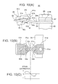
- FIGS. 10 (A) through 10 (C) are views for explaining the actions of the structure around a sensor plate of a seat weight measuring apparatus according to the first embodiment of the present invention.
- FIG. 10 (A) is a side view thereof
- FIG. 10 (B) is a plan view of the sensor plate
- FIG. 10 (C) is a graph schematically illustrating strain distribution on the surface of the sensor plate.
- FIG. 11 is a side view for explaining the action when axial force (force in the longitudinal direction) is applied to supports of half arms according to the first embodiment of the present invention.
- FIG. 12 is a graph showing data indicating the influences of the axial force applied to the supports of the half arms on the measurement data according to the first embodiment of the present invention.
- FIG. 6 (A) is a front sectional view schematically showing a structural example for fixing a seat to a vehicle body and FIG. 6 (B) is a side view thereof.
- arrows in the drawings indicate as follows.
- UP the opposite direction of the gravitational direction when the vehicle is placed horizontally
- DOWN the gravitational direction
- FORWARD the forward direction of the vehicle
- BACKWARD the reverse direction of the vehicle
- LEFT the left side as facing the forward direction of the vehicle
- RIGHT the right side as facing the same.
- a seat 3 is shown in FIGS. 6 (A), 6 (B).
- a passenger 1 sits on a seat squab 3 a of the seat 3 .
- the seat squab 3 a is supported at its lower surface by a seat frame 5 made of a steel plate.
- the seat frame 5 comprises components including a bottom plate 5 a , lateral plates 5 c , vertical plates 5 e , and slide plates 5 g .
- the bottom plate 5 a extends to cover the lower surface of the seat squab 3 a .
- the lateral plates 5 c extend along the left and right sides of the lower surface of the bottom plate 5 a .
- the vertical plates 5 e are hung from the center portions of the lower surfaces of the lateral plates 5 c , respectively.
- the slide plates 5 g project right and left of the respective vertical plates 5 e like wings and the end portions of each slide plate 5 g are bent upward.
- Each seat rail 7 is arranged beneath right and left portions of the seat 3 so as to extend in the forward and backward direction (the lengthwise direction) and parallel to each other.
- the cross section of each seat rail 7 is formed in a U-like shape and has a concavity 7 c therein and a groove 7 a formed in the upper portion of the concavity 7 c . Inserted in the groove 7 a is the vertical plate 5 e of the seat frame 5 .
- the slide plate 5 g of the seat frame 5 is housed in the concavity 7 c of the seat rail 7 .
- the slide plate 5 g is slidable in the lengthwise direction in the seat rail 7 .
- the seat weight measuring apparatus 9 Connected to the lower surface of each seat rail 7 is a seat weight measuring apparatus 9 .
- the seat weight measuring apparatus 9 has an elongated box-like profile extending in the lengthwise direction. The seat weight measuring apparatus 9 will be detailed later.
- seat brackets 11 Attached to front and rear ends of the lower surface of the seat weight measuring apparatus 9 are seat brackets 11 .
- the seat brackets 11 are fixed to seat fixing portions 13 of the vehicle body by means of bolts.
- FIGS. 2 (A)- 2 (D) are views illustrating the entire construction of a seat weight measuring apparatus according to a first embodiment of the present invention.
- FIG. 2 (A) is a plan view thereof
- FIG. 2 (B) is a side sectional view thereof
- FIGS. 2 (C) and 2 (D) are front sectional views thereof.
- FIGS. 2 (A) and 2 (B) the illustration of the seat weight measuring apparatus on the rear side is omitted.
- FIG. 3 is a partially broken perspective view showing the details of the construction around a sensor plate.
- FIGS. 4 (A) through 4 (C) show a structural example of the sensor plate of the seat weight measuring apparatus according to the first embodiment of the present invention.
- FIG. 4 (A) is a plan view showing the details of the construction of the sensor plate
- FIG. 4 (B) is a side sectional view of the sensor plate taken along the line X—X of FIG. 4 (A)
- FIG. 4 (C) is a circuit diagram of the sensor.
- FIGS. 5 (A)- 5 (C) are views showing the relation between the sensor plate and half arms.
- FIG. 5 (A) is a plan view thereof
- FIG. 5 (B) is a side view thereof when no load is applied
- FIG. 5 (C) is a side view thereof when a load is applied.
- the seat weight measuring apparatus 9 comprises an elongate base 21 as a substrate.
- the base 21 extends lengthwise in the forward and backward direction when mounted to the vehicle body and is a product made by the press-working of a steel plate having a U-shaped cross section, as shown in FIGS. 2 (C), 2 (D).
- the bottom of the base 21 is referred as to a bottom plate 21 c and portions which stand from the left and right edges of the bottom plate 21 c to form corners of 90° there between are referred to as side plates 21 a , 21 a′.
- Each of the base side plates 21 a , 21 a ′ is provided with two pairs of pin holes 21 e and 21 g in front and rear portions, respectively.
- the pin holes 21 e , 21 g are formed to face the pin holes 21 e , 21 g of the opposite side plates 21 a , 21 a′.
- the holes 21 e near the front and rear ends of the base 21 are formed in portions away at a distance from the front and rear ends, respectively, wherein the distance corresponds to approximately 1 ⁇ 8 of the overall length of the base 21 .
- the holes 21 e are vertically elongated holes, as shown in FIG. 2 (B). Inserted through the elongated holes 21 e are ends of bracket pins 27 .
- each bracket pin 27 is transmitting the seat weight exerted on the pin bracket 25 to a Z arm 23 .
- the pin holes 21 g are formed in positions closer to the center than the positions of the elongated holes 21 e (at a distance corresponding to approximately ⁇ fraction (1/10) ⁇ of the overall length of the base 21 from the elongated hole 21 e ). Inserted into the holes 21 g are base pins 31 . Each of the base pins 31 extends to bridge the left and right side plates 21 a , 21 a ′. Fitted on the left and right ends of the pin 31 are retainers 33 , thereby fixing the base pin 31 to the base 21 .
- the base pin 31 is the pivot shaft of the Z arm 23 .
- the Z arms 23 are arranged inside of the base 21 .
- Each of the Z arms 23 has a center portion, when seen in plan view, which is forked (into two branches 23 h ) and has a rectangular portion near the end.
- the Z arm 23 has side plates 23 a , 23 a ′ formed by upwardly folding left and right edge portions thereof by 90°.
- the side plates 23 a , 23 a ′ extend from the end to the middle portion.
- the branches 23 h are only flat plates.
- the side plates 23 a , 23 a ′ extend along the inner surfaces of the side plates 21 a , 21 a ′ of the base 21 . There are clearances between the side plates 23 a , 23 a ′ and the side plates 21 a , 21 a′.
- Each of the Z arm side plates 23 a , 23 a ′ is provided with two pin holes 23 c , 23 e formed therein. Inserted into the pin holes 23 c formed near the end is the bracket pin 27 . The bracket pin 27 and the pin holes 23 c slide little relative to each other. Inserted into the pin holes 23 e at the center side is the base pin 31 .
- the base pin 31 is the pivot of the Z arm 23 , so the base pin 31 and the pin holes 23 e slide relative to each other by pivotal movement of the Z arm 23 .
- the length of the branches 23 h of the Z arm 23 corresponds substantially to a half of the overall length of the Z arm 23 .
- the branches 23 h are separated from each other to the right and left and extend toward the center of the base 21 .
- Each of the branches 23 h has a reduced width near the center.
- the action portions 23 j at the ends of the branches 23 h are clamped between wings 41 a , 42 a of upper and lower half arms 41 , 42 as shown in FIGS. 3 and 5 (A) through 5 (C).
- the Z arm 23 slightly pivots (the maximum pivotal angle being approximately 5°) whereby the action portions 23 j transmit the load to the sensor plate 51 through the half arms 41 , 42 .
- the pin bracket 25 is formed to have an inverted U-shaped cross section as shown in FIG. 2 (C).
- the length of the pin bracket 25 in the forward and backward direction substantially corresponds to ⁇ fraction (1/20) ⁇ of that of the base 21 .
- the pin bracket 25 has a flat upper surface 25 a on which the seat rail 7 shown in FIGS. 6 (A), 6 (B) is mounted.
- the seat rail 7 is strongly fixed to the pin brackets 25 by bolts or other fastening means.
- the pin bracket 25 has left and right side plates 25 b downwardly projecting, of which lower ends are bent inwardly.
- the pin bracket 25 is disposed inside the Z arm 23 in such a manner as to have clearances between the side plates 25 b and the Z arm side plates 23 a , 23 a ′.
- the side plates 25 b are provided with pin holes 25 c formed therein. Inserted into the pin holes 25 c is a bracket pin 27 .
- the inner diameter of each pin hole 25 c is larger than the diameter of the bracket pin 27 . The clearance between them absorbs dimensional tolerance of the seat and the vehicle body and/or unexpected deformation.
- a spring plate 29 Disposed between the side plates 25 b of the pin bracket 25 and the side plates 23 a , 23 a ′ of the Z arm 23 is a spring plate 29 having spring washer portions with holes.
- the bracket pin 27 is loosely inserted into the holes of the spring washer portions.
- the spring plate 29 composes a centering mechanism for biasing the pin bracket 25 toward the center.
- the centering mechanism as mentioned above causes the pin bracket 25 to be positioned as close to the center in the slidable range as possible.
- the movement of the slide mechanism and the pivotal mechanism after the installation of the seat weight measuring apparatus can be secured in the both directions (right and left, up and down, forward and backward).
- FIGS. 4 (A) through 4 (C) show a structural example of the sensor plate of the seat weight measuring apparatus according to the first embodiment of the present invention.
- FIG. 4 (A) is a plan view of the sensor plate
- FIG. 4 (B) is a side sectional view of the sensor plate taken along the line X—X of FIG. 4 (A)
- FIG. 4 (C) is a circuit diagram of the sensor.
- an insulating layer (lower insulating layer) 52 for electrical insulation.
- a wiring layer 53 is formed on the insulating layer 52 .
- a resistant layer 54 which composes the strain gauge.
- an insulating layer (upper insulating layer) 55 is applied over these layers as a protective layer. In this manner, the electrical circuit including resistors is directly laminated on the spring steel plate 51 , thereby reducing the working cost and the assembly cost and further improving the heat resistance and the corrosion resistance.
- the sensor plate 51 is a rectangular plate having two necks as a whole.
- the sensor plate 51 is provided with a central hole 51 a formed in the center thereof and bolt holes 51 b formed in end portions thereof.
- the sensor 50 is formed around the central hole 51 a and between the central hole 51 a and the bolt holes 51 b .
- V-like concavities are provided in both side edges of regions 51 c between the central hole 51 a and the bolt holes 51 b . These concavities ensure positions to be deformed of the sensor plate 51 , thereby preventing positional variation of dislocation and stabilizing the sensitivity of the sensor 50 .
- the sensor 50 is substantially symmetrical about the center of the central hole 51 a .
- the sensor 50 is composed of four strain gauges 54 a , 54 b , 54 c , and 54 d . Two of them 54 a , 54 b to be applied with tensile strain are arranged near the bolt holes 51 b (near the ends), while the other two strain gauges 54 c , 54 d to be applied with compressive strain are arranged near the central hole 51 a (central side).
- the strain gauges 54 a , 54 b , 54 c , and 54 d are connected to each other by wirings 53 a , 53 b , 53 c , and 53 d to form a bridge circuit shown in FIG. 4 (C). Squares marked by numerals 1 , 2 , 3 , 4 in FIGS. 4 (A), 4 (C) are terminals.
- a sensitivity control resistor 54 e Arranged between the strain gauges 54 a , 54 c and the strain gauges 54 b , 54 d is a sensitivity control resistor 54 e.
- the load may be obtained by conversion from deflection of the sensor plate 51 detected by electrical capacitance pressure sensors or Hall elements, instead of the detection of dislocation of the sensor plate 51 being detected by the strain gauges 54 a , 54 b , 54 c , and 54 d.
- the sensor plate 51 is strongly fixed to the top of a column 63 at the center of the base bottom plate 21 c by means of a washer 67 and a nut 68 .
- the half arms 41 , 42 are provided in the form of two pairs to be arranged above and below of the front and rear portions of the sensor plate 51 to clamp the sensor plate 51 . Since the half arms 41 , 42 have same configuration, a description will be made as to only an upper half arm 41 .
- the half arm 41 comprises a half arm body 41 c which is a rectangular plate with an attachment hole 41 e (FIGS. 5 (B), 5 (C)) formed in the center thereof.
- the half arm 41 further comprises wings 41 a extending in the right and left directions from edges of the body 41 c near the sensor plate center, and levee-like supports 41 b formed on the backs of the wings 41 a and extending in the right and left directions.
- the top of each support 41 b is slightly edged.
- the wings 41 a , 42 a of the upper and lower half arms 41 , 42 are arranged in such a manner that the supports 41 b , 42 b confront each other. Sandwiched between the supports 41 b , 42 b are the action portions 23 j of the Z arm 23 .
- the supports are positioned at the middle (the neck (the region 51 c ) of the sensor plate 51 ) of a region between the two strain gauges 54 a and 54 c or 54 d and 54 b.
- FIG. 5 (C) schematically and exaggeratedly shows the state of the sensor plate and the half arms.
- FIGS. 1 (A), 1 (B) are views showing the dislocation/deflection absorbing mechanism for the seat weight measuring apparatus of this embodiment.
- FIG. 1 (A) is an exploded perspective view thereof and
- FIG. 1 (B) is a front sectional view of a pin bracket.
- the pin bracket 25 is securely fixed to the seat rail 7 by a bolt or the like.
- the constructions of the respective components and their assembling relation of the seat weight measuring apparatus 9 have been described above with reference to FIG. 3 .
- dislocation is absorbed by forming the pin hole 25 c of the pin bracket 25 into an elongated hole.
- dislocation is absorbed mainly by spaces between the side plates 25 b of the pin bracket 25 and the side plates 23 a of the Z arm.
- dislocation is absorbed mainly by spaces between the side plates 25 b of the pin bracket 25 and the side plates 23 a of the Z arm, as well as the vertical direction of the vehicle body.
- dislocation is absorbed mainly by rotation of the pin bracket 25 about the bracket pin 27 .
- the absorbing mechanism of the seat weight measuring apparatus of this embodiment can slide the following L UD [mm] or more relative to the vertical direction of the vehicle body.
- H 1 dimensional error [mm] of the legs of the seat in the vertical direction
- H 2 dimensional error [mm] of the seat fixing portions of the vehicle body in the vertical direction
- ⁇ deflection amount per unit load [mm/kgf] when three of four legs of the seat are fixed and the residual one is deformed in the vertical direction
- FIGS. 7 (A), 7 (B) are views for explaining the way of examining the slidable dimension of the absorbing mechanism relative to the vertical direction of the vehicle body.
- FIG. 7 (A) shows the dimensional error of the seat.
- the seat means a unit comprising a seat frame (designated by a numeral 5 in FIG. 6) and a seat rail (designated by a numeral 7 in FIG. 6 ).
- FIG. 7 (B) shows the dimensional error of the seat mounting portions 13 of the vehicle body. There is an error H 2 on one of the seat mounting portions 13 when a flat surface 10 formed by the other three seat mounting portions 13 is assumed as a reference surface.
- the load sensor mechanism may deform a value obtained by multiplying the sum of F A (assembly load) and F by a deformation amount ⁇ per unit load in the vertical direction of the load sensor mechanism wherein F is the sum of F S (the seat itself) and F M (a person or an object on the seat) and the sum of F A and F is the total weight to be applied to the seat weight measuring apparatus.
- the absorbing mechanism should absorb the deforming value.
- the absorbing mechanism of this embodiment can slide the following L LR or more relative to the width direction of the vehicle body.
- FIGS. 8 (A), 8 (B) are views for explaining the way of examining the slidable dimension of the absorbing mechanism relative to the width direction of the vehicle body.
- FIG. 8 (A) shows a state before a load is applied and
- FIG. 8 (B) shows a state after the load is applied.
- FIGS. 8 (A), 8 (B) show the seat 3 , the seat frame 5 , and the seat brackets 11 . It should be noted that the seat frame 5 shown in the drawings includes the seat rails 7 .
- “x” is a distance from the center of the seat in the width direction to the center Z 1 , Z 1 ′ of the right or left seat leg.
- the height of each seat bracket 11 is “y”.
- the absorbing mechanism should further absorb the original dimensional tolerance c.
- the slidable dimension L LR of the absorbing mechanism in the width direction is given by the following expression in which the deflection amount L S is subtracted from the sum of the deflection between the center of the seat leg and the center of the seat bracket and the dimensional tolerance.
- the absorbing mechanism of this embodiment can rotate by ⁇ LR or more about an axis extending in a widthwise direction of the vehicle body:
- ⁇ LR tan ⁇ 1 ( H/W )
- H a difference in height between the front leg and the rear leg of the seat (connecting points) and
- W a space between the front leg and the rear leg of the seat (connecting points).
- the clearance between pin hole 25 c of the pin bracket 25 and bracket pin 27 allows the absorbing mechanism to rotate about an axis extending in a vertical direction of the vehicle body.
- the degree of pivoting allowed is more than a difference from parallel of the seat rails.
- FIG. 9 (A) is a side sectional view showing the construction of a seat weight measuring apparatus according to a second embodiment of the present invention.
- FIG. 9 (B) is a perspective view showing the detailed structure of a load cell, hollow suspension, and XY slider according to the second embodiment.
- a seat weight measuring apparatus 100 is arranged between the seat rail 7 and the seat mounting portion 11 of the vehicle body or between the seat frame 5 and the seat rail 7 .
- the seat weight measuring apparatus 100 comprises load cells 105 , hollow suspensions 103 , and XY sliders 102 .
- Each load cell 105 includes a strain gauge therein to measure the seat weight.
- Each load cell 105 is fixed to the seat mounting portion 11 by a fixing plate 107 .
- Each hollow suspension 103 is a member transmitting a load to each load cell 105 .
- Each hollow suspension 103 is a hollow member having a relatively small thickness. Therefore, the hollow suspension 103 can elastically deform in the vertical, lengthwise, and width directions.
- Each XY slider 102 is a disk-like member and is engaged with a disk-like concavity 101 a of a base 101 with a space therebetween.
- the XY slider 102 can slide in the lengthwise and width directions (XY directions) within the concavity 101 a.
- the hollow suspensions 103 and the XY sliders 102 compose an absorbing mechanism of this seat weight measuring apparatus 100 .
- FIGS. 10 (A) through 10 (C) are views for explaining the actions of the structure around the sensor plate of the seat weight measuring apparatus according to the first embodiment of the present invention.
- FIG. 10 (A) is a side view thereof
- FIG. 10 (B) is a plan view of the sensor plate
- FIG. 10 (C) is a graph schematically illustrating strain distribution on the surface of the sensor plate. It should be noted that these figures show only the front half and the central portion of the sensor plate.
- FIG. 11 is a side view for explaining the action when axial force (force in the longitudinal direction) is applied to the supports of the half arms.
- FIG. 12 is a graph showing data indicating the influences of the axial force applied to the supports of the half arms on the measurement data.
- the Z arm 23 slightly pivots upwardly (see FIG. 2 (B)) according to the seat weight to raise up the supports 41 b of the wings 41 a of the half arm 41 .
- moment M is transmitted from the half arm body 41 c to the sensor plate 51 .
- the sensor plate 51 is deformed in wave-like profile so as to create a region 51 y of which strain is tensile (+) and a region 51 z of which strain is compressional ( ⁇ ).
- a portion between the load applied portion 51 x and the central fixed portion 51 w has such a plane configuration that two triangular portions are disposed to oppose to each other about the neck 51 c as shown in FIG. 1 (B). Formed on this portion are the tension-side constant surface strain region 51 y and the compression-side constant surface strain region 51 z . Attached to the regions 51 y and 51 z are a tension-side strain gauge 54 a and a compression-side strain gauge 54 c , respectively.
- the tension-side strain gauge and the compression-side strain gauge are wired on the bridge circuit in such a manner as to form an opposite phase, thereby increasing the outputs of the strain gauges. This attains high precise measurement with small strains on the sensor, thereby increasing the life of the sensor.
- strain gauges are attached (printed) on regions providing constant surface strain, so strain may not vary even through the positions of strain gauges are slightly shifted, thereby preventing measurement error. Therefore, this can ensure high precision of measurement and can reduce quality requirement on manufacturing.
- strains are concentrated in portions on which the strain gauges are attached, highly precise measurement is performed and measurement error can be prevented even with manufacturing error and/or assembling error of other parts.
- force W is applied from the action portions 23 j of the Z arm 23 to the supports 41 b of the wings 41 a of the half arm 41 .
- the force W is mainly composed of vertical component W v because of the structure of the half arm 23 .
- the force W may partially composed of horizontal component (axial force) W h . Due to elongation or dislocation of the Z arm 23 , frictional force may act on the supports 41 b in the lateral direction.
- Hysteresis in the outputs of the compression-side strain gauge and the tension-side strain gauge is clearly shown in this graph, the hysteresis being developed by rise and fall in load. This is because axial force is produced between the Z arms and the half arms during rise or fall in load.
- nearly non hysteresis is shown so that the data of the total output is almost linear. This is because the axial force is cancelled as described in the above.
- the load applied points 41 b of the half arm 41 and the center line in the thickness of the sensor plate 51 are set to be in substantially the same level or have height difference of ⁇ 5 mm or less. According to this structure, when frictional force (axial force W h ) acts on the action points 41 b , the moment arm for deforming the sensor plate due to the frictional force is short. This means that the deformation of the sensor plate due to the frictional force is little, thereby reducing the measurement error.
- the present invention can provide a seat weight measuring apparatus in which the performance of load sensors is not spoiled due to dimensional error or deformation of a vehicle body or a seat. Further, the present invention can provide a seat weight measuring apparatus which has good durability and high precision but can be manufactured at low cost. Further still, the present invention can provide a seat weight measuring apparatus with reduced measurement error due to manufacturing error of parts of a mechanism and/or frictional force.
Abstract
Description
Claims (20)
Applications Claiming Priority (4)
| Application Number | Priority Date | Filing Date | Title |
|---|---|---|---|
| JP06134199A JP3444810B2 (en) | 1999-03-09 | 1999-03-09 | Seat weight measuring device |
| JP06134099A JP4129336B2 (en) | 1999-03-09 | 1999-03-09 | Seat weight measuring device |
| JP11-061341 | 1999-03-09 | ||
| JP11-061340 | 1999-03-09 |
Publications (1)
| Publication Number | Publication Date |
|---|---|
| US6571647B1 true US6571647B1 (en) | 2003-06-03 |
Family
ID=26402384
Family Applications (1)
| Application Number | Title | Priority Date | Filing Date |
|---|---|---|---|
| US09/521,912 Expired - Lifetime US6571647B1 (en) | 1999-03-09 | 2000-03-09 | Seat weight measuring apparatus |
Country Status (2)
| Country | Link |
|---|---|
| US (1) | US6571647B1 (en) |
| DE (2) | DE20004393U1 (en) |
Cited By (34)
| Publication number | Priority date | Publication date | Assignee | Title |
|---|---|---|---|---|
| US20020109063A1 (en) * | 2000-10-19 | 2002-08-15 | Paul Jaudouin | Runner for a vehicle seat and a system for a vehicle including a seat equipped with such a runner |
| US20020154020A1 (en) * | 2001-03-23 | 2002-10-24 | Chiaki Sumi | Passenger weight measuring apparatus |
| US20030067196A1 (en) * | 2001-09-13 | 2003-04-10 | Kazunori Sakamoto | Attachment structure of a load sensor for a vehicle seat |
| US20030131671A1 (en) * | 2001-12-18 | 2003-07-17 | Tachi-S Co., Ltd. | Load detection structure for vehicle seat |
| US20030177847A1 (en) * | 2002-03-19 | 2003-09-25 | Tachi-S Co., Ltd | Load detection structure in a sliding seat |
| US20040000198A1 (en) * | 2002-06-28 | 2004-01-01 | Konrad Wolf | Force sensor |
| US20040003668A1 (en) * | 2002-07-08 | 2004-01-08 | Tachi-S Co., Ltd. | Load detection structure for vehicle seat |
| US20040035224A1 (en) * | 2002-08-21 | 2004-02-26 | Takata Corporation | Seat load measuring apparatus |
| US20040140137A1 (en) * | 2001-05-01 | 2004-07-22 | Bizerba Gmbh & Co. Kg | Vehicle seat |
| US20040201264A1 (en) * | 2003-02-13 | 2004-10-14 | Jochen Hofmann | Seat assembly for a motor vehicle seat |
| US20040206191A1 (en) * | 2003-04-18 | 2004-10-21 | Takata Corporation | Seat-load measuring apparatus |
| US20040231435A1 (en) * | 2003-04-18 | 2004-11-25 | Takata Corporation | Seat load measuring apparatus |
| US20040237668A1 (en) * | 2003-04-18 | 2004-12-02 | Takata Corporation | Seat-load measuring apparatus |
| US20050016777A1 (en) * | 2002-08-26 | 2005-01-27 | Kiyoshi Saito | Fixing device and weight measuring apparatus using the same |
| US20050023045A1 (en) * | 2003-07-31 | 2005-02-03 | Takata Corporation | Seat weight measuring apparatus |
| US20050044969A1 (en) * | 2003-08-26 | 2005-03-03 | Takata Corporation | Seat weight measuring apparatus |
| US20050056101A1 (en) * | 2003-09-17 | 2005-03-17 | Murphy Morgan D. | Non-uniform rigidity interface panel for a fluid-filled seat bladder |
| US20050066748A1 (en) * | 2003-09-30 | 2005-03-31 | Takata Corporation | Seat weight measuring apparatus |
| US20050150313A1 (en) * | 2000-11-28 | 2005-07-14 | Siemens Vdo Automotive Corporation | Sensor assembly for measuring weight applied to a vehicle seat |
| US20050167166A1 (en) * | 2004-01-29 | 2005-08-04 | Vogel Mark S. | Occupant classification sense element |
| US6952975B2 (en) | 2003-03-31 | 2005-10-11 | Denso Corporation | Seat occupant sensor with stopper mechanism |
| US20050229721A1 (en) * | 2003-01-31 | 2005-10-20 | Keiper Gmbh & Co. Kg | Sensor device for a vehicle seat |
| US20050242554A1 (en) * | 2004-04-28 | 2005-11-03 | Takata Corporation | Seat load measuring device and occupant protection system using the same |
| US20060167604A1 (en) * | 2005-01-24 | 2006-07-27 | Trw Automotive U.S. Llc | System and method for adjusting a zero point of a seat load sensing system |
| US20060175096A1 (en) * | 2005-02-09 | 2006-08-10 | Trw Automotive U.S. Llc | System and method for drift compensation in a seat load sensing system |
| US20060185446A1 (en) * | 2005-02-18 | 2006-08-24 | Speckhart Frank H | Printed strain gage for vehicle seats |
| US20070010935A1 (en) * | 2005-07-08 | 2007-01-11 | Trw Automotive U.S. Llc | System and process for adjusting a zero point of a seat load sensing system |
| US20080007100A1 (en) * | 2006-06-23 | 2008-01-10 | Aisin Seiki Kabushiki Kaisha | Load detecting device for vehicle seat |
| US20090126500A1 (en) * | 2007-11-21 | 2009-05-21 | Aisin Seiki Kabushiki Kaisha | Load detection device |
| US20100038940A1 (en) * | 2008-08-18 | 2010-02-18 | Jae-Ho Hwang | Passenger distinguishing apparatus |
| US7676339B2 (en) * | 2004-10-12 | 2010-03-09 | Robert Bosch Gmbh | Apparatus and method of compensating a seat offset for a load applied to the seat |
| US20110043009A1 (en) * | 2009-08-24 | 2011-02-24 | Aisin Seiki Kabushiki Kaisha | Apparatus and method for determining impact on vehicle and apparatus for warning impact on vehicle |
| US20120012405A1 (en) * | 2010-07-19 | 2012-01-19 | Robert Bosch Gmbh | Occupant weight sensing using intelligent fastener and vertical load transmitting brackets |
| US11719557B2 (en) | 2019-12-24 | 2023-08-08 | Joyson Safety Systems Acquisition Llc | Apparatus and method of producing a sensing substrate |
Families Citing this family (4)
| Publication number | Priority date | Publication date | Assignee | Title |
|---|---|---|---|---|
| US6636792B2 (en) | 2000-09-29 | 2003-10-21 | Siemens Vdo Automotive Corporation | Weight classification system |
| DE60112963T2 (en) | 2000-11-28 | 2006-02-23 | Siemens Vdo Automotive Corporation, Auburn Hills | WEIGHT SENSOR ARRANGEMENT WITH OVERLOAD SPRING |
| US6849807B2 (en) | 2001-06-13 | 2005-02-01 | Kavlico Corporation | Seat weight measurement system |
| JP3690383B2 (en) * | 2002-10-16 | 2005-08-31 | マツダ株式会社 | Vehicle occupant detection device |
Citations (8)
| Publication number | Priority date | Publication date | Assignee | Title |
|---|---|---|---|---|
| US5319161A (en) * | 1992-12-24 | 1994-06-07 | Pitney Bowes Inc. | Mechanism for preventing overload on a weighing scale |
| JPH111153A (en) | 1997-06-13 | 1999-01-06 | Takata Kk | Seat device of vehicle and air bag device |
| JPH11304579A (en) | 1998-04-16 | 1999-11-05 | Takata Kk | Seat weight measuring apparatus |
| US6039344A (en) * | 1998-01-09 | 2000-03-21 | Trw Inc. | Vehicle occupant weight sensor apparatus |
| US6089106A (en) * | 1998-09-04 | 2000-07-18 | Breed Automotive Technology, Inc. | Force sensor assembly |
| US6109117A (en) * | 1996-12-19 | 2000-08-29 | Automotive Systems Laboratory, Inc. | Seat weight sensor |
| US6161439A (en) * | 1997-05-12 | 2000-12-19 | Stanley; James Gregory | Seat belt tension prediction |
| US6323444B1 (en) * | 1999-03-09 | 2001-11-27 | Takata Corporation | Seat weight measuring apparatus |
Family Cites Families (2)
| Publication number | Priority date | Publication date | Assignee | Title |
|---|---|---|---|---|
| JPH09269258A (en) * | 1996-04-01 | 1997-10-14 | Tec Corp | Load cell |
| GB2333070B (en) * | 1998-01-12 | 2002-01-09 | Autoliv Dev | Improvements in or relating to a safety arrangement in a motor vehicle |
-
2000
- 2000-03-09 DE DE20004393U patent/DE20004393U1/en not_active Expired - Lifetime
- 2000-03-09 US US09/521,912 patent/US6571647B1/en not_active Expired - Lifetime
- 2000-03-09 DE DE10011371A patent/DE10011371B4/en not_active Expired - Fee Related
Patent Citations (9)
| Publication number | Priority date | Publication date | Assignee | Title |
|---|---|---|---|---|
| US5319161A (en) * | 1992-12-24 | 1994-06-07 | Pitney Bowes Inc. | Mechanism for preventing overload on a weighing scale |
| US6109117A (en) * | 1996-12-19 | 2000-08-29 | Automotive Systems Laboratory, Inc. | Seat weight sensor |
| US6161439A (en) * | 1997-05-12 | 2000-12-19 | Stanley; James Gregory | Seat belt tension prediction |
| JPH111153A (en) | 1997-06-13 | 1999-01-06 | Takata Kk | Seat device of vehicle and air bag device |
| US6039344A (en) * | 1998-01-09 | 2000-03-21 | Trw Inc. | Vehicle occupant weight sensor apparatus |
| JPH11304579A (en) | 1998-04-16 | 1999-11-05 | Takata Kk | Seat weight measuring apparatus |
| US6069325A (en) * | 1998-04-16 | 2000-05-30 | Takata Corporation | Seat weight measuring apparatus |
| US6089106A (en) * | 1998-09-04 | 2000-07-18 | Breed Automotive Technology, Inc. | Force sensor assembly |
| US6323444B1 (en) * | 1999-03-09 | 2001-11-27 | Takata Corporation | Seat weight measuring apparatus |
Cited By (62)
| Publication number | Priority date | Publication date | Assignee | Title |
|---|---|---|---|---|
| US6767029B2 (en) * | 2000-10-19 | 2004-07-27 | Faurecia Sieges D'automobile S.A. | Runner for a vehicle seat and a system for a vehicle including a seat equipped with such a runner |
| US20020109063A1 (en) * | 2000-10-19 | 2002-08-15 | Paul Jaudouin | Runner for a vehicle seat and a system for a vehicle including a seat equipped with such a runner |
| US7047825B2 (en) * | 2000-11-28 | 2006-05-23 | Siemens Vdo Automotive Corporation | Sensor assembly for measuring weight applied to a vehicle seat |
| US20050150313A1 (en) * | 2000-11-28 | 2005-07-14 | Siemens Vdo Automotive Corporation | Sensor assembly for measuring weight applied to a vehicle seat |
| US20020154020A1 (en) * | 2001-03-23 | 2002-10-24 | Chiaki Sumi | Passenger weight measuring apparatus |
| US6922152B2 (en) * | 2001-03-23 | 2005-07-26 | Aisin Seiki Kabushiki Kaisha | Passenger weight measuring apparatus |
| US6903280B2 (en) | 2001-05-01 | 2005-06-07 | Bizerba Gbmh & Co. Kg | Vehicle seat |
| US20040140137A1 (en) * | 2001-05-01 | 2004-07-22 | Bizerba Gmbh & Co. Kg | Vehicle seat |
| US20030067196A1 (en) * | 2001-09-13 | 2003-04-10 | Kazunori Sakamoto | Attachment structure of a load sensor for a vehicle seat |
| US6981717B2 (en) * | 2001-09-13 | 2006-01-03 | Aisin Seiki Kabushiki Kaisha | Attachment structure of a load sensor for a vehicle seat |
| US20030131671A1 (en) * | 2001-12-18 | 2003-07-17 | Tachi-S Co., Ltd. | Load detection structure for vehicle seat |
| US6748814B2 (en) * | 2001-12-18 | 2004-06-15 | Tachi-S Co., Ltd. | Load detection structure for vehicle seat |
| US20030177847A1 (en) * | 2002-03-19 | 2003-09-25 | Tachi-S Co., Ltd | Load detection structure in a sliding seat |
| US6729193B2 (en) * | 2002-03-19 | 2004-05-04 | Tachi-S Co., Ltd. | Load detection structure in a sliding seat |
| US6865961B2 (en) * | 2002-06-28 | 2005-03-15 | Robert Bosch Gmbh | Force sensor |
| US20040000198A1 (en) * | 2002-06-28 | 2004-01-01 | Konrad Wolf | Force sensor |
| US20040003668A1 (en) * | 2002-07-08 | 2004-01-08 | Tachi-S Co., Ltd. | Load detection structure for vehicle seat |
| US6739206B2 (en) * | 2002-07-08 | 2004-05-25 | Tachi-S Co., Ltd. | Load detection structure for vehicle seat |
| US7399932B2 (en) | 2002-08-21 | 2008-07-15 | Takata Corporation | Seat load measuring apparatus |
| US20040035224A1 (en) * | 2002-08-21 | 2004-02-26 | Takata Corporation | Seat load measuring apparatus |
| US20050016777A1 (en) * | 2002-08-26 | 2005-01-27 | Kiyoshi Saito | Fixing device and weight measuring apparatus using the same |
| US7038146B2 (en) * | 2002-08-26 | 2006-05-02 | Matsushita Electric Industrial Co., Ltd. | Fixing device including a screw arranged with clearance in a fixing hole, and a weight measuring apparatus using the same |
| US7360460B2 (en) | 2003-01-31 | 2008-04-22 | Keiper Gmbh & Co. Kg | Sensor device for a vehicle seat |
| US20050229721A1 (en) * | 2003-01-31 | 2005-10-20 | Keiper Gmbh & Co. Kg | Sensor device for a vehicle seat |
| US7513571B2 (en) * | 2003-02-13 | 2009-04-07 | Brose Fahrzeugteile Gmbh & Co.Kg, Coburg | Seat assembly for a motor vehicle seat |
| US20040201264A1 (en) * | 2003-02-13 | 2004-10-14 | Jochen Hofmann | Seat assembly for a motor vehicle seat |
| US6952975B2 (en) | 2003-03-31 | 2005-10-11 | Denso Corporation | Seat occupant sensor with stopper mechanism |
| US20040231435A1 (en) * | 2003-04-18 | 2004-11-25 | Takata Corporation | Seat load measuring apparatus |
| US6943695B2 (en) | 2003-04-18 | 2005-09-13 | Takata Corporation | Seat load measuring apparatus |
| US7096745B2 (en) | 2003-04-18 | 2006-08-29 | Takata Corporation | Seat-load measuring apparatus |
| US20040237668A1 (en) * | 2003-04-18 | 2004-12-02 | Takata Corporation | Seat-load measuring apparatus |
| US7000489B2 (en) | 2003-04-18 | 2006-02-21 | Takata Corporation | Seat-load measuring apparatus |
| US20040206191A1 (en) * | 2003-04-18 | 2004-10-21 | Takata Corporation | Seat-load measuring apparatus |
| US7173198B2 (en) | 2003-07-31 | 2007-02-06 | Takata Corporation | Seat weight measuring apparatus |
| US20050023045A1 (en) * | 2003-07-31 | 2005-02-03 | Takata Corporation | Seat weight measuring apparatus |
| US7044006B2 (en) | 2003-08-26 | 2006-05-16 | Takata Corporation | Seat weight measuring apparatus |
| US20050044969A1 (en) * | 2003-08-26 | 2005-03-03 | Takata Corporation | Seat weight measuring apparatus |
| US20050056101A1 (en) * | 2003-09-17 | 2005-03-17 | Murphy Morgan D. | Non-uniform rigidity interface panel for a fluid-filled seat bladder |
| US6886417B2 (en) * | 2003-09-17 | 2005-05-03 | Delphi Technologies, Inc. | Non-uniform rigidity interface panel for a fluid-filled seat bladder |
| US7237442B2 (en) | 2003-09-30 | 2007-07-03 | Takata Corporation | Seat weight measuring apparatus |
| US20050066748A1 (en) * | 2003-09-30 | 2005-03-31 | Takata Corporation | Seat weight measuring apparatus |
| US20050167166A1 (en) * | 2004-01-29 | 2005-08-04 | Vogel Mark S. | Occupant classification sense element |
| US20050242554A1 (en) * | 2004-04-28 | 2005-11-03 | Takata Corporation | Seat load measuring device and occupant protection system using the same |
| US7676339B2 (en) * | 2004-10-12 | 2010-03-09 | Robert Bosch Gmbh | Apparatus and method of compensating a seat offset for a load applied to the seat |
| US7684913B2 (en) | 2005-01-24 | 2010-03-23 | Trw Automotive U.S. Llc | System and method for adjusting a zero point of a seat load sensing system |
| US20060167604A1 (en) * | 2005-01-24 | 2006-07-27 | Trw Automotive U.S. Llc | System and method for adjusting a zero point of a seat load sensing system |
| US20060175096A1 (en) * | 2005-02-09 | 2006-08-10 | Trw Automotive U.S. Llc | System and method for drift compensation in a seat load sensing system |
| US7363184B2 (en) | 2005-02-09 | 2008-04-22 | Trw Automotive U.S. Llc | System and method for drift compensation in a seat load sensing system |
| US20060185446A1 (en) * | 2005-02-18 | 2006-08-24 | Speckhart Frank H | Printed strain gage for vehicle seats |
| US20070240524A1 (en) * | 2005-02-18 | 2007-10-18 | Speckhart Frank H | Printed Strain Gauge for Vehicle Seats |
| US20070010935A1 (en) * | 2005-07-08 | 2007-01-11 | Trw Automotive U.S. Llc | System and process for adjusting a zero point of a seat load sensing system |
| US20080007100A1 (en) * | 2006-06-23 | 2008-01-10 | Aisin Seiki Kabushiki Kaisha | Load detecting device for vehicle seat |
| US7762150B2 (en) * | 2006-06-23 | 2010-07-27 | Aisin Seiki Kabushiki Kaisha | Load detecting device for vehicle seat |
| US7823459B2 (en) * | 2007-11-21 | 2010-11-02 | Aisin Seiki Kabushiki Kaisha | Load detection device |
| US20090126500A1 (en) * | 2007-11-21 | 2009-05-21 | Aisin Seiki Kabushiki Kaisha | Load detection device |
| US20100038940A1 (en) * | 2008-08-18 | 2010-02-18 | Jae-Ho Hwang | Passenger distinguishing apparatus |
| US8136620B2 (en) * | 2008-08-18 | 2012-03-20 | Hyundai Mobis Co., Ltd | Passenger distinguishing apparatus having weight detection sensor and damper |
| US20110043009A1 (en) * | 2009-08-24 | 2011-02-24 | Aisin Seiki Kabushiki Kaisha | Apparatus and method for determining impact on vehicle and apparatus for warning impact on vehicle |
| US8328276B2 (en) * | 2009-08-24 | 2012-12-11 | Aisin Seiki Kabushiki Kaisha | Apparatus and method for determining impact on vehicle and apparatus for warning impact on vehicle |
| US20120012405A1 (en) * | 2010-07-19 | 2012-01-19 | Robert Bosch Gmbh | Occupant weight sensing using intelligent fastener and vertical load transmitting brackets |
| US8766112B2 (en) * | 2010-07-19 | 2014-07-01 | Robert Bosch Gmbh | Occupant weight sensing using intelligent fastener and vertical load transmitting brackets |
| US11719557B2 (en) | 2019-12-24 | 2023-08-08 | Joyson Safety Systems Acquisition Llc | Apparatus and method of producing a sensing substrate |
Also Published As
| Publication number | Publication date |
|---|---|
| DE20004393U1 (en) | 2000-08-03 |
| DE10011371A1 (en) | 2000-09-14 |
| DE10011371B4 (en) | 2010-04-15 |
Similar Documents
| Publication | Publication Date | Title |
|---|---|---|
| US6571647B1 (en) | Seat weight measuring apparatus | |
| US6323444B1 (en) | Seat weight measuring apparatus | |
| US6323443B1 (en) | Seat weight measuring apparatus | |
| US6069325A (en) | Seat weight measuring apparatus | |
| EP1434042A1 (en) | ( Seat ) Load plate with double bridge for temperature compensation | |
| US6342683B1 (en) | Weight sensor for vehicle occupant | |
| US6586948B1 (en) | Vehicle seat weight measuring device | |
| US6617531B1 (en) | Seat load measuring device | |
| US6345543B1 (en) | Seat weight measuring apparatus | |
| US6755571B2 (en) | Rotational and bearing structures and a seat-weight measuring apparatus | |
| US6859753B1 (en) | Apparatus and method for measuring the weight of an occupant in a vehicle | |
| JP3468728B2 (en) | Seat weight measuring device | |
| US6786104B1 (en) | Seat weight measuring apparatus | |
| JP2002168682A (en) | Load detecting structure of slide seat for vehicle | |
| JP5003430B2 (en) | Vehicle seat load detection device | |
| JP2003270030A (en) | Load detection structure for slide sheet for vehicle | |
| JP3444810B2 (en) | Seat weight measuring device | |
| JP2000258233A (en) | Seat weight measuring device | |
| US9389116B2 (en) | Weight detection sensor and vehicle seat apparatus including a strain body between the floor and the vehicle seat | |
| JP3663406B2 (en) | Seat weight measuring device | |
| JP2004345362A (en) | Weight measurement system, weight measurement method, and load transfer link | |
| US6943695B2 (en) | Seat load measuring apparatus | |
| JP2004517779A (en) | Device for measuring the force acting on a vehicle seat | |
| WO2006099746A1 (en) | Automotive weight sensor for occupant classification system | |
| US20040262049A1 (en) | Seat weight measuring device |
Legal Events
| Date | Code | Title | Description |
|---|---|---|---|
| AS | Assignment |
Owner name: TAKATA CORPORATION, JAPAN Free format text: ASSIGNMENT OF ASSIGNORS INTEREST;ASSIGNORS:AOKI, HIROSHI;KUSAKA, SHUJI;REEL/FRAME:010915/0779;SIGNING DATES FROM 20000425 TO 20000426 |
|
| STCF | Information on status: patent grant |
Free format text: PATENTED CASE |
|
| FEPP | Fee payment procedure |
Free format text: PAYOR NUMBER ASSIGNED (ORIGINAL EVENT CODE: ASPN); ENTITY STATUS OF PATENT OWNER: LARGE ENTITY |
|
| FPAY | Fee payment |
Year of fee payment: 4 |
|
| FPAY | Fee payment |
Year of fee payment: 8 |
|
| FPAY | Fee payment |
Year of fee payment: 12 |
|
| AS | Assignment |
Owner name: JOYSON SAFETY SYSTEMS JAPAN K.K., JAPAN Free format text: ASSIGNMENT OF ASSIGNORS INTEREST;ASSIGNOR:TAKATA CORPORATION;REEL/FRAME:045938/0931 Effective date: 20180410 |
|
| AS | Assignment |
Owner name: DEUTSCHE BANK TRUST COMPANY AMERICAS, NEW YORK Free format text: SECURITY INTEREST;ASSIGNOR:JOYSON SAFETY SYSTEMS JAPAN K. K.;REEL/FRAME:046286/0789 Effective date: 20180525 |
|
| AS | Assignment |
Owner name: JOYSON SAFETY SYSTEMS JAPAN K.K., JAPAN Free format text: RELEASE BY SECURED PARTY;ASSIGNOR:DEUTSCHE BANK TRUST COMPANY AMERICAS, AS SECURITY AGENT FOR THE SECURED PARTIES;REEL/FRAME:057775/0655 Effective date: 20211004 |