US6567858B1 - Optimal all-to-all personalized exchange in optical multistage networks - Google Patents

Optimal all-to-all personalized exchange in optical multistage networks Download PDF

Info

Publication number
US6567858B1
US6567858B1 US09/400,004 US40000499A US6567858B1 US 6567858 B1 US6567858 B1 US 6567858B1 US 40000499 A US40000499 A US 40000499A US 6567858 B1 US6567858 B1 US 6567858B1
Authority
US
United States
Prior art keywords
permutations
processors
permutation
network
semi
Prior art date
Legal status (The legal status is an assumption and is not a legal conclusion. Google has not performed a legal analysis and makes no representation as to the accuracy of the status listed.)
Expired - Fee Related
Application number
US09/400,004
Inventor
Jianchao Yang
Yuan Yuan Yang
Current Assignee (The listed assignees may be inaccurate. Google has not performed a legal analysis and makes no representation or warranty as to the accuracy of the list.)
University of Vermont
Verizon Laboratories Inc
Verizon Patent and Licensing Inc
Original Assignee
University of Vermont
Verizon Laboratories Inc
Priority date (The priority date is an assumption and is not a legal conclusion. Google has not performed a legal analysis and makes no representation as to the accuracy of the date listed.)
Filing date
Publication date
Priority to US09/400,004 priority Critical patent/US6567858B1/en
Application filed by University of Vermont, Verizon Laboratories Inc filed Critical University of Vermont
Assigned to GTE LABORATORIES INCORPORATED reassignment GTE LABORATORIES INCORPORATED ASSIGNMENT OF ASSIGNORS INTEREST (SEE DOCUMENT FOR DETAILS). Assignors: WANG, JIANCHAO
Assigned to VERIZON LABORATORIES INC. reassignment VERIZON LABORATORIES INC. ASSIGNMENT OF ASSIGNORS INTEREST (SEE DOCUMENT FOR DETAILS). Assignors: GTE LABORATORIES INCORPORATED
Application granted granted Critical
Publication of US6567858B1 publication Critical patent/US6567858B1/en
Assigned to MERRILL LYNCH CAPITAL CORPORATION, AS COLLATERAL AGENT reassignment MERRILL LYNCH CAPITAL CORPORATION, AS COLLATERAL AGENT COLLATERAL AGREEMENT Assignors: LEVEL 3 COMMUNICATIONS, INC., VERIZON COMMUNICATIONS
Assigned to GENUITY, INC. reassignment GENUITY, INC. ASSIGNMENT OF ASSIGNORS INTEREST (SEE DOCUMENT FOR DETAILS). Assignors: GTE SERVICE CORPORATION
Assigned to LEVEL 3 COMMUNICATIONS, INC. reassignment LEVEL 3 COMMUNICATIONS, INC. ASSIGNMENT OF ASSIGNORS INTEREST (SEE DOCUMENT FOR DETAILS). Assignors: GENUITY, INC.
Assigned to LEVEL 3 COMMUNICATIONS, INC. reassignment LEVEL 3 COMMUNICATIONS, INC. RELEASE OF SECURITY INTEREST Assignors: MERRILL LYNCH CAPITAL CORPORATION, AS COLLATERAL AGENT
Assigned to MERRILL LYNCH CAPITAL CORPORATION, AS COLLATERAL AGENT reassignment MERRILL LYNCH CAPITAL CORPORATION, AS COLLATERAL AGENT SECURITY AGREEMENT Assignors: ICG COMMUNICATIONS, INC., LEVEL 3 COMMUNICATIONS, INC.
Assigned to LEVEL 3 COMMUNICATIONS, LLC reassignment LEVEL 3 COMMUNICATIONS, LLC ASSIGNMENT OF ASSIGNORS INTEREST (SEE DOCUMENT FOR DETAILS). Assignors: LEVEL 3 COMMUNICATIONS, INC.
Assigned to GENUITY INC., VERIZON CORPORATE SERVICES GROUP, INC. reassignment GENUITY INC. ASSIGNMENT OF ASSIGNORS INTEREST (SEE DOCUMENT FOR DETAILS). Assignors: GTE LABORATORIES INCORPORATED
Assigned to MERRILL LYNCH CAPITAL CORPORATION, AS COLLATERAL AGENT reassignment MERRILL LYNCH CAPITAL CORPORATION, AS COLLATERAL AGENT CORRECTIVE ASSIGNMENT TO CORRECT THE RECORDATION FORM COVER SHEET PREVIOUSLY RECORDED ON REEL 016301 FRAME 0495. ASSIGNOR(S) HEREBY CONFIRMS THE COLLATERAL AGREEMENT. Assignors: LEVEL 3 COMMUNICATIONS, INC.
Assigned to VERIZON PATENT AND LICENSING INC. reassignment VERIZON PATENT AND LICENSING INC. ASSIGNMENT OF ASSIGNORS INTEREST (SEE DOCUMENT FOR DETAILS). Assignors: LEVEL 3 COMMUNICATIONS, LLC, VERIZON CORPORATE SERVICES GROUP INC.
Assigned to LEVEL 3 COMMUNICATIONS, LLC reassignment LEVEL 3 COMMUNICATIONS, LLC RELEASE BY SECURED PARTY (SEE DOCUMENT FOR DETAILS). Assignors: MERRILL LYNCH CAPITAL CORPORATION
Anticipated expiration legal-status Critical
Expired - Fee Related legal-status Critical Current

Links

Images

Classifications

    • HELECTRICITY
    • H04ELECTRIC COMMUNICATION TECHNIQUE
    • H04QSELECTING
    • H04Q11/00Selecting arrangements for multiplex systems
    • H04Q11/0001Selecting arrangements for multiplex systems using optical switching
    • H04Q11/0005Switch and router aspects
    • HELECTRICITY
    • H04ELECTRIC COMMUNICATION TECHNIQUE
    • H04QSELECTING
    • H04Q11/00Selecting arrangements for multiplex systems
    • H04Q11/0001Selecting arrangements for multiplex systems using optical switching
    • H04Q11/0005Switch and router aspects
    • H04Q2011/0007Construction
    • H04Q2011/0024Construction using space switching
    • HELECTRICITY
    • H04ELECTRIC COMMUNICATION TECHNIQUE
    • H04QSELECTING
    • H04Q11/00Selecting arrangements for multiplex systems
    • H04Q11/0001Selecting arrangements for multiplex systems using optical switching
    • H04Q11/0005Switch and router aspects
    • H04Q2011/0052Interconnection of switches
    • H04Q2011/0054Distribute-route

Definitions

  • This application relates to the field of parallel computing and networking, and more specifically to all-to-all personalized exchange in multistage networks.
  • processors may be a design issue when, for example, a parallel processing system is built, or a parallel procedure is designed. With advances in silicon and Ga—As technologies, processor speed may soon reach the gigahertz (GHz) range. Traditional metal-based communication technology used in parallel computing systems is becoming a potential bottleneck. Progress in the traditional interconnects, or to in the new interconnect technologies, such as optics, would be well received in the parallel computing systems community.
  • GHz gigahertz
  • Fiber optic communications offer a combination of high bandwidth, low error probability, and gigabit transmission capacity. They have been extensively used in wide-area networks and have received much attention in the parallel processing community as well. In fact, many commercial, massively parallel computers, such as the Cray C90, use optical technology in their communication subsystems.
  • Multistage interconnection networks hereafter also referred to as multistage networks, have been used for interconnecting purposes in parallel computing systems.
  • a MIN can be blocking, such as a Banyan network, rearrangeably non-blocking, such as a Benes network, non-blocking, such as crossbar.
  • a MIN may have variably connecting capabilities, from rearrangeable for permutation to non-blocking for multicast, such as in a Clos-network, depending on the number of stages, the number of switches, the switch capability, and the interconnection patterns used between stages.
  • optical technology As optical technology advances, there has been a growing interest in using optical technology for implementing interconnection networks and switches. Although electronic MINs and optical MINs have many similarities, here are some fundamental differences between them. Because of some unique properties of optics, traditional routing procedures and results may not be applicable here. New research addressing optical MINs may be useful.
  • All-to-all personalized exchange occurs in many important parallel computing/networking applications, such as matrix transposition and fast Fourier transform (FFT).
  • FFT fast Fourier transform
  • a basic element of optical switching networks is a directional coupler with two inputs and two outputs (hereafter referred to simply as switches). Depending on the control voltage applied to it, an input optical signal is coupled to either of the two outputs, setting the switch to either the parallel or the crossing state.
  • a class of topologies that can be used to construct optical networks is multistage interconnection networks (MINs), which interconnect their inputs and outputs via several stages of switches.
  • optical communication a promising networking choice to meet the increasing demands for high channel bandwidth and low communication latency of high-performance computing/communication applications.
  • optical multistage networks hold great promise and have demonstrated advantages over their electronic counterpart, they also introduce new challenges such as how to deal with the unique problem of avoiding crosstalk in the optical switches, which may occur when two signal channels in a switch interact with each other.
  • optical signals can interact in a planar switching network.
  • the channels carrying the signals may cross each other in order to embed a particular topology.
  • two paths sharing a switch may experience some undesired coupling from one path to another within a switch. It would be desirable to achieve optical exchange in multistage networks in a manner that reduces crosstalk.
  • optical multistage interconnection networks MSNs
  • optical MINs hold great promise and have demonstrated advantages over their electronic counterparts, they also present their own problems. Due to certain optical properties, crosstalk in optical switches should be avoided if they are to work efficiently.
  • the concept of a semi-permutation is introduced to analyze the permutation capability of optical MINs under the constraint of avoided crosstalk in several types of MINs.
  • an optimal scheme for realizing crosstalk-free all-to-all personalized exchange in a class of unique-path, self-routing optical multistage networks is presented.
  • the basic idea of realizing all-to-all personalized exchange in such a multistage network is to transform it to a collection of the above-mentioned semi-permutations.
  • Each of the semi-permutations can be realized crosstalk-free in a single pass (i.e., in a single, concurrent exchange of signals) and can take advantage of pipelined message transmission in consecutive passes.
  • a method for crosstalk-free all-to-all exchange in an optical multistage network having inputs and outputs coupled to processors comprises sending messages between the processors in multiple passes, wherein, in each of the multiple passes, each of the processors transmits, in one-to-one fashion, a message to one of the processors by way of the inputs and outputs, in accord with semi-permutations decomposed from permutations corresponding to rows of a matrix.
  • the optical multistage network may be one of a baseline network, omega network, Banyan network, and their reverse networks.
  • each of the processors may transmit, in one-to-one fashion, a message to one of the processors by way of the inputs and outputs, in accord with semi-permutations decomposed from permutations corresponding to rows of a Latin square.
  • the semi-permutations may be obtained by computing two input sets.
  • a method for crosstalk-free all-to-all exchange in an optical multistage network having n inputs and n outputs coupled to n processors, where n ⁇ 2, 4, 8, 16, . . . ⁇ and wherein each of the n processors is connected to one of the n inputs and one of the n outputs, comprising computing a Latin square having n rows and n columns; associating the n rows with n admissible permutations, each of the n admissible permutations being a one-to-one mapping from N ⁇ 0,1, . . . ,n ⁇ 1 ⁇ to itself; for j a member of the set ⁇ 1, 2, . . .
  • n ⁇ decomposing a jth permutation, from among the n admissible permutations, into two semi-permutations, one of the two semi-permutations, s (j) , being a restriction of said mapping to a subset, S (j) , of N having n/2 elements, and another of the two semi-permutations, t (j) , being a restriction of said mapping to a subset, T (j) , of N where T (j) is a complement N ⁇ S (j) ; sending n/2 messages in a (2j ⁇ 1)th pass, and n/2 messages in a (2j)th pass, each of the messages departing from one of the n processors, traveling through one of the n inputs and one of the n outputs, and arriving at one of the n processors, wherein a kth processor from among the n processors sends a message to an Ith processor from among the n processors in the (2j-1)th pass if, and only
  • Computing a Latin square having n rows and n columns may include computing a Latin square off-line.
  • the optical multistage network may be one of a baseline network, omega network, Banyan network, and their reverse networks.
  • the method may further comprise composing each of the n admissible permutations as a composition of 2m ⁇ 1 permutations, a jth permutation from among the n admissible permutations composed as
  • n ⁇ 2 a method of achieving all-to-all crosstalk-free exchange in an optical multistage network, said network having an even number, n ⁇ 2, of processors, comprising computing an n ⁇ n matrix ⁇ [ a 0 , 0 a 0 , 1 ... a 0 , n - 1 a 1 , 0 a 1 , 1 ... a 1 , n - 1 ⁇ ⁇ ⁇ ⁇ a n - 1 , 0 a n - 1 , 1 ... a n - 1 , n - 1 ]
  • ⁇ (j) is given by ( 0 1 2 ... n - 1 a j , 0 a j , 1 a j , 2 ... a j , n - 1 ) ;
  • s (j) is a restriction of the permutation ⁇ (j) to a subset, S (j) , of N having n/2 elements
  • t (j) is a restriction of the permutation ⁇ (j) to a subset, T (j) , of N
  • n ⁇ instructions for said processors to decompose a jth permutation from among the n admissible permutations into two semi-permutations, one of the two semi-permutations, s (j) , being a restriction of said mapping to a subset, S (j) , of N having n/2 elements, and another of the two semi-permutations, t (j) , being a restriction of said mapping to a subset, T (j) , of N where T (j) is a complement N ⁇ S (j) ; instructions for said processors to initiate the transmittal of n/2 messages in a (2j ⁇ 1)th pass, and n/2 messages in a (2j)th pass, each of the messages departing from one of the n processors, traveling through one of the n inputs and one of the n outputs, and arriving at one of the n processors, wherein a kth processor from among the n processors sends a message to an Ith processor from among the
  • n instructions for said processors to continue to send n/2 messages in a (2j ⁇ 1)th pass, and n/2 messages in a (2j)th pass until n 2 messages have been sent, and 2n passes have occurred, corresponding to 2n decompositions of the n admissible permutations.
  • the optical multistage network may include one of a Banyan network, an omega network, a baseline network, and their reverse networks.
  • the instructions for the processors to decompose a jth permutation from among the n admissible permutations into two semi-permutations may include computing two input sets in a time of the order O(n).
  • a system for crosstalk-free all-to-all exchange in an optical multistage network comprises processors; and instructions for said processors to send messages between the processors in multiple passes, wherein, in each of the multiple passes, each of the processors transmits, in one-to-one fashion, a message to one of the processors in accord with semi-permutations decomposed from permutations corresponding to rows of a matrix.
  • the matrix may be a Latin square.
  • the instructions for said processors to send messages between the processors may include instructions to compute input sets from which the semi-permutations may be obtained in a time on the order of O(n) where the Latin square is an n ⁇ n matrix. Instructions may be included to compute two input sets from which the semi-permutations may be obtained.
  • FIG. 1 shows three examples of multistage networks of the prior art
  • FIG. 2 shows examples of semi-permutations that can and cannot be realized in an 8 ⁇ 8 baseline network
  • FIG. 3 shows a routing example in an 8 ⁇ 8 baseline network
  • FIG. 4 shows an example of basic permutations for an 8 ⁇ 8 mapping
  • FIG. 5 shows all of the possible switch settings in which each stage is set to either parallel or crossing in an 8 ⁇ 8 baseline network
  • FIG. 6 shows all crosstalk-free routings corresponding to the semi-permutations decomposed from the permutations which form a Latin square in an 8 ⁇ 8 baseline network;
  • FIG. 8 shows the 3-bit Gray code sequence generated in one embodiment by applying basic permutations.
  • FIG. 9 shows a flow chart indicating some steps for achieving crosstalk-free, all-to-all exchange.
  • FIG. 10 shows an embodiment of the present invention involving teleconferencing.
  • a semi-permutation which is a decomposition of a mathematical permutation (a more precise definition appears below), may be introduced as a useful tool for designing crosstalk-free routing in an optical multistage network in a manner described below.
  • the properties of semi-permutations in the context of crosstalk-free routing are explored, and all-to-all personalized exchange procedures in optical multistage networks based on crosstalk-free semi-permutations are developed.
  • realizing all-to-all personalized exchange in an optical multistage network involves associating multistage networks with multiple semi-permutations each of which can be realized crosstalk-free in a single pass, and taking advantage of pipelined message transmission in consecutive passes.
  • an 8 ⁇ 8 baseline network 11 an omega network 12 , and a Banyan network 13 are shown.
  • Each network includes network inputs 16 and outputs 17 , and interstage links 14 , and stages 15 .
  • a permutation is a one-to-one mapping between the network inputs and outputs. Any permutation may be realized in a Benes network in a single pass (in the electronic version), and any permutation can be realized in a Benes network in two passes crosstalk-free (in the optical version).
  • the switch setting in a Benes network is complex and expensive, which may discourage people to choose this type of network for a high speed communication environment.
  • a full permutation capability may not be necessary for all-to-all personalized exchange.
  • a class of unique-path, self-routing multistage networks such as baseline 11 , omega 12 , Banyan 13 networks, and their reverse networks are considered.
  • a baseline network 11 , an omega network 12 , and a Banyan network 13 are examples of network configurations that have several advantages. These networks, for example, impose less hardware cost (almost half of that of a Benes network), and have fast switch settings (self-routing) at the stages 15 .
  • the limitations of networks such as a baseline network 11 , an omega network 12 , and a Banyan network 13 are that not every permutation is admissible to such a network, and not every admissible permutation to the network can be decomposed to semi-permutations which, can be realized in a single pass crosstalk-free in the network.
  • Such message exchanges initiate at processors (not shown in FIG. 1) each of which may be connected to one input and one output (eight inputs 16 and eight outputs 17 are shown in FIG. 1 .).
  • the message proceeds from one of the inputs 16 , through one of the stages 15 and one of the interstage links 14 , then through more stages IS and interstage links 14 , in alternating fashion, until the message exits through one of the network outputs 17 . From the network outputs, the message arrives at a processor.
  • a permutation is a one-to-one mapping between the network inputs and outputs.
  • ( 0 1 ... n - 1 a 0 a 1 ... a n - 1 )
  • this permutation is referred to as an identity permutation and is denoted by I.
  • a permutation which is realizable by the multistage network is referred to as an admissible permutation of the network.
  • ⁇ 1 ⁇ 2 of the two permutations is also a permutation, which maps i to ⁇ 1 ( ⁇ 2 (i)).
  • switches When realizing a permutation in an optical multistage network in a single pass, as discussed earlier, switches suffer crosstalk. Semi-permutations may be introduced as a useful tool for crosstalk-free routing in an optical multistage network consisting of 2 ⁇ 2 switches.
  • a semi-permutation is defined as a one-to-one mapping between some n/2 inputs ⁇ x 0 , x 1 , . . , x n/2 ⁇ 1 ⁇ and some n/2 outputs ⁇ (y 0 ,y 1 , . . .
  • a semi-permutation is a partial permutation that ensures that there is only one active link passing through each input switch and output switch.
  • the use of semi-permutations helps eliminate crosstalk in the first and last stages in the network, Thus, semi-permutations may be realized in an optical network crosstalk-free. To ensure that the entire network is crosstalk-free, signals must travel crosstalk-free through the switches in the intermediate stages as well.
  • one semi-permutation is referred to as the twin of the other. Let the two semi-permutations be s and t, respectively. Then
  • InputSet( s ) ⁇ InputSet( t )OutputSet( s ) ⁇ OutputSet( t ) ⁇ 0, 1, . . . , n ⁇ 1 ⁇ .
  • a semi-permutation can be realized in a multistage network in a single pass crosstalk-free, it is referred to as a crosstalk-free semi permutation for this network.
  • FIG. 2 examples of semi-permutations for an 8 ⁇ 8 baseline network are depicted. Paths 21 show that ⁇ ( 0 2 4 6 3 5 7 1 )
  • each switch supports one, and only one, path.
  • Paths 25 do not represent a crosstalk-free semi-permutation because two switches support two paths each, while two other switches support no paths.
  • the bold boxes 26 and 27 indicate the two switches with crosstalk.
  • Lemma 1 For the two semi-permutations decomposed from an admissible permutation of a multistage network, if one is crosstalk-free for the network, so is the other.
  • a decomposition of a permutation is called a crosstalk-free decomposition to a multistage network if its semi-permutations are crosstalk-free realizable to the network.
  • composition of permutations to semi-permutations may also be extended.
  • a composition s 1 s 2 is defined as the mapping that i is mapped to s 1 (s 2 (i)) for i ⁇ InputSet(s 2 ).
  • the composition of two semi-permutations s 1 and s 2 is also a semi-permutation with the input set being InputSet(s 2 ) and the output set being OutputSet(s 1 ).
  • the composition of more than one semi-permutation may be defined iteratively.
  • s 1 s 2 be a composition of two semi-permutations s 1 and s 2
  • each stage and each interstage link in the network may be viewed as a shorter n ⁇ n network.
  • ⁇ i (0 ⁇ i ⁇ m ⁇ 1) denote the permutation represented by stage i
  • ⁇ i (0 ⁇ i ⁇ m ⁇ 2) denote the permutation represented by the set of interstage links between stage i and stage i+1.
  • the permutation ⁇ i , and the permutation ⁇ i are known as a stage and an interstage permutation, respectively.
  • An admissible permutation of a multistage network can be expressed by a composition of stage permutations and interstage permutations.
  • an admissible permutation of a baseline network can be expressed as
  • interstage permutations ⁇ i 's are fixed by the network topology.
  • n ⁇ 1 ⁇ is p m ⁇ 1 p m ⁇ 2 . . . p 1 p 0 .
  • permutation ⁇ i represents the following mapping p m - 1 ⁇ p m - 2 ⁇ ... ⁇ ⁇ p 1 ⁇ p 0 ⁇ ⁇ ⁇ i ⁇ p m - 1 ⁇ p m - 2 ⁇ ... ⁇ ⁇ p m - i ⁇ p 0 ⁇ p m - i - 1 ⁇ ... ⁇ ⁇ p 2 ⁇ p 1 ( 4 )
  • each switch is set to a parallel configuration 31 or a crossing configuration 32 .
  • Lemma 2 Let an admissible permutation of a multistage network shown in (3) be denoted by ⁇ 2m ⁇ 1 ⁇ 2m ⁇ 2 . . . ⁇ 2 ⁇ 1 .
  • the admissible permutation can be decomposed into two crosstalk-free semi-permutations if and only if permutation ⁇ i can be decomposed into two semi-permutations s i and t i for 1 ⁇ 2m ⁇ 1 such that
  • InputSet( s 2m ⁇ 1 ) OutputSet( s 2m ⁇ 2 )
  • InputSet( s 2m ⁇ 2 ) Output(Set( s m ⁇ 3 )
  • InputSet( s 2 ) OutputSet( s 1 ) (5)
  • the two crosstalk-free semi-permutations obtained are s 2m ⁇ 1 s 2m ⁇ 2 . . . s 2 s 1 and t 2m ⁇ 1 t 2m ⁇ 2 . . . t 2 t 1 , respectively.
  • t 2 t 1 are semi-permutations with the input set InputSet(s 1 ) and InputSet(t 1 ), and the output set OutputSet(s 2m ⁇ 1 ) and OutputSet(t 2m ⁇ 1 ), respectively. Therefore, the admissible permutation is decomposed into two crosstalk-free semi-permutations s 2m ⁇ 1 s 2m ⁇ 2 . . . s 2 s 1 and t 2m ⁇ 1 t 2m ⁇ 2 . . . t 2 t 1 .
  • An approach to realizing all-to-all personalized exchange in multistage networks without the constraint of crosstalk-free, i.e., in (ordinary) electronic multistage networks, may be introduced.
  • the approach may then be extended to realize all-to-all personalized exchange in optical multistage networks under the constraint of crosstalk-free.
  • processor i (0 ⁇ i ⁇ n ⁇ 1) be connected to input i and ouput i of the network to other processors and receive messages from other processors through output i of the network.
  • Lemma 3 The maximum communication delay of all-to-all personalized exchange in an all n x n network of log n stages is at least ⁇ (n+log n).
  • a Latin square is defined as an n ⁇ n matrix ⁇ [ a 0 , 0 a 0 , 1 ... a 0 , n - 1 a 1 , 0 a 1 , 1 ... a 1 , n - 1 ⁇ ⁇ ⁇ ⁇ a n - 1 , 0 a n - 1 , 1 ... a n - 1 , n - 1 ]
  • entries a ij 's are numbers in ⁇ 0, 1, 2, . . . n ⁇ 1 ⁇ and no two entries in a row (or a column) have the same value.
  • a i0 ,a i1 , . . . , a i,n ⁇ 1 corresponds to a permutation ( 0 1 2 ... n - 1 a i , 0 a i , 1 a i , 2 ... a i , n - 1 ) ,
  • processor j sends distinct messages to all destinations in the order of a 0j ,a 1j , . . . , a n ⁇ 1j , which corresponds to the column j of the Latin square.
  • all n processors send their messages simultaneously to destinations a i,0 ,a i,1 , . . . , a i,n ⁇ 1 , which corresponds to the row i, of the Latin square.
  • all-to-all personalized exchange is achieved by realizing n permutations which correspond to the n rows of the Latin square, since under the assumption that each permutation represented by a row of the Latin square is admissible to the network.
  • the network under consideration is a self-routing network, where each switch is set automatically by the routing tag contained in the message passing that switch. Since admissible permutations are being considered, at any time two messages entering from the two inputs of a switch can pass the switch simultaneously without any conflicts. In addition, once the previous n messages leave the switches of the cUrrent stage, the next n messages can enter the switches of this stage. Thus, the sequential steps of 2.1 are actually performed in a pipelined fashion, which achieves a form of parallelism. Therefore, the time complexities of Step 1 and Step 2 are O(n) and O(n+log n), respectively. The total time delay for all-to-all personalized exchange procedure is O(n+log n), which generally matches the low bound of the communication delay for this type of network.
  • Procedure ATAPE begin Step 1. for each processor j (0 ⁇ j ⁇ n-1) do in parallel 1.1 for each ⁇ ij (0 ⁇ i ⁇ n-1) in the Latin square do in sequential prepare a personalized message from processor j to processor ⁇ ij ; insert the message into the message queue j; Step 2. for each processor j (0 ⁇ j ⁇ n-1) do in parallel 2.1 for each message with destination address ⁇ ij (0 ⁇ i ⁇ n-1) in the message queue j do in sequential send message destined to ⁇ ij through input j of the network; end;
  • the permutation ⁇ i is actually the operation flipping the i th bit of a binary number.
  • the first permutation corresponds to the ⁇ 1 basic permutation 41 , the second permutation to the ⁇ 2 basic permutation 42 , and the third permutation to the ⁇ 3 basic permutation.
  • Each arc in FIG. 4 represents a mapping between two numbers.
  • Theorem 2 Let the stage permutation of each stage in a baseline network take either ⁇ 1 or I, The admissible permutations corresponding to all possible such switch settings form a Latin square.
  • routing pattern 51 has switch settings I, I, and I in columns one, two, and three respectively and corresponds to the first row of the Latin square L;
  • the routing pattern 52 has switch settings I,I, and ⁇ 1 in columns one, two, and three respectively and corresponds to the second row of the Latin square L;
  • the routing pattern 53 has switch settings I, ⁇ 1 , and ⁇ 1 in columns one,two, and three respectively and corresponds to the third row of the Latin square L;
  • the routing pattern 54 has switch settings I, ⁇ 1 , and I in columns one, two, and three respectively and corresponds to the fourth row of the Latin square L;
  • the routing pattern 55 has switch settings ⁇ 1 , ⁇ 1 , and I in columns one, two, and three respectively and corresponds to the fifth row of the Latin square L;
  • the routing pattern 56 has switch settings ⁇ 1 , ⁇ 1 , and ⁇ 1 in columns one, two, and three respectively and corresponds to the sixth row of the Latin square L;
  • the routing pattern 57 has switch settings ⁇
  • the routing pattern 58 has switch settings ⁇ 1 , I, and I in columns one, two, and three respectively and corresponds to the eighth row of the Latin square L.
  • the semi-permutation is said to be self-mapping, if the intersection of the two sets is empty (in other words, the union of the two sets is the whole set ⁇ 0, 1 , . . . , n ⁇ 1 ⁇ , the semi-permutation is said to be opposite-mapping.
  • Bits(x) is a function of the integer x that returns the number of 1's in the binary representation of x.
  • a ⁇ B is empty.
  • ⁇ A ⁇ ( m 0 ) + ( m 2 ) + ( m 4 ) + ... ⁇ ⁇
  • the second part of (9) may be proven. For example, for an 8 ⁇ 8 network,
  • mapping ⁇ i only shifts some bits and does not change the total number of 1's.
  • ⁇ i (x) ⁇ A For any x ⁇ A, ⁇ i (x) ⁇ A. That is, ⁇ i is a one-to-one self-mapping of A.
  • A ⁇ x 0 ,x 1 , . . . , x n/2 ⁇ with x 0 ⁇ x 1 ⁇ . . . ⁇ x n/2 .
  • ⁇ 0 ( 0 1 2 3 4 5 6 7 0 4 1 5 2 6 3 7 ) ⁇ ⁇ decomposed ⁇ ⁇ to ⁇ ⁇ ( 0 3 5 6 0 5 6 3 ) ⁇ ⁇ and ⁇ ⁇ ( 1 2 4 7 4 1 2 7 )
  • n ⁇ n network which could be a baseline, omega, Banyan, or their reverse networks, can be decomposed to two self-mapping semi-permutations with the input sets being A and B respectively.
  • Theorem 4 Let the stage permutation ⁇ i of each stage in a baseline network take either ⁇ 1 or I. Then any admissible permutation shown in (3) has a crosstalk-free decomposition of semi-permutations.
  • ⁇ 1 ⁇ 0 can be decomposed to two crosstalk-free semi-permutations s m ⁇ 2 s m ⁇ 2 s m ⁇ 3 . . . s 1 s 0 and t m ⁇ 2 m m ⁇ 3 . . . t 1 t 0 , which are self-mapping.
  • one crosstalk-free semi-permutation need only be constructed; its twin can be obtained symmetrically.
  • First take a semi-permutation ⁇ 0,s decomposed from ⁇ 0 with the input set A regardless ⁇ 0 I or ⁇ 1 .
  • Then take a semi-permutation ⁇ 0,s decomposed from ⁇ 0 with the input set A or B depending on ⁇ 0 I or ⁇ 1 .
  • step i take semi-permutation ⁇ i,s decomposed from ⁇ i with the input set equal to OutputSet( ⁇ i ⁇ 1,s ⁇ i ⁇ 1,s . . .
  • FIG. 6 (FIGS. 6A and 6B) all crosstalk-free routings are listed that correspond to the semi-permutations decomposed from permutations which form a Latin square in (7), in an 8 ⁇ 8 baseline network.
  • 2n passes of crosstalk-free routings are possible.
  • routing patterns 611 and 612 have switch settings I, I, and I in columns one, two, and three respectively and correspond to the first row the Latin square L; the routing patterns 621 and 622 have switch settings I, I, and ⁇ 1 in columns one, two, and three respectively and correspond to the second row of the Latin square L; the routing patterns 631 and 632 have switch settings I, ⁇ 1 , and ⁇ 1 in columns one, two, and three respectively and correspond to the third row of the Latin square L; the routing pattern 641 and 642 have switch settings I, ⁇ 1 , and I in columns one, two, and three respectively and correspond to the fourth row of the Latin square L; the routing pattern 651 and 652 have switch settings ⁇ 1 , ⁇ 1 , and I in columns one, two, and three respectively and correspond to the fifth row of the Latin square L; the routing pattern 661 and 662 have switch settings ⁇ 1 , ⁇ 1 , and ⁇ 1 in columns one, two, and three respectively and correspond to the sixth row of the Latin square L; the routing patterns 6
  • the routing pattern 681 and 682 have switch settings ⁇ 1 , I, and I in columns one, two, and three respectively and correspond to the eighth row of the Latin square L.
  • O(n) time procedure to generate sets A and B is given.
  • Binary numbers 71 correspond to numbers with an even number of 1s in their binary representation.
  • Binary numbers 72 correspond to numbers with an odd number of 1s in their binary representation.
  • the resultant procedure for calculating the sets A and B is shown in Table II.
  • GenSemiSets( ⁇ ) included below calls a recursive function GenTag( ⁇ ) to generate a tag list of 0's and 1's, then builds the set A and B based on the tag list.
  • the function Negate( ⁇ ) used in GenTag( ⁇ ) returns a new tag list with each tag negated from corresponding tag in the input tag list; while the function Concat( ⁇ ) returns a concatenation of two tag list.
  • Theorem 5 The permutation ⁇ 0 has a unique self-mapping decomposition.
  • Theorem 6 The special admissible permutation described above has a unique crosstalk/free decomposition such that each of the semi-permutations decomposed from a stage permutation and an interstage permutation is self-mapping or opposite-mapping.
  • Lemma 7 Let ⁇ 0.s and ⁇ 0.t be self-mapping semi-permutations decomposed from ⁇ 0 . Given c and d (0 ⁇ c, d ⁇ n ⁇ 1) with binary representations p m ⁇ 1 p m ⁇ 2 . . . p i+1 p i p i ⁇ 1 . . . p 1 p 0 and p m ⁇ 1 p m ⁇ 2 . . . p i+1 ⁇ overscore (p) ⁇ i p i ⁇ 1 . . . p 1 0 , respectively, where 0 ⁇ i ⁇ m ⁇ 1, if c is in the input set of one of the semi-permutations, then d is in the input set of the twin semi-permutations.
  • swap mapping which swaps a pair of 0 and 1 in the binary representation of an integer. Since any such swap mapping does not change the number of 1's in the binary representation, if h ⁇ H K and h is mapped to h′ by swap mapping, then h′ ⁇ H K . The result that if h ⁇ C then h′ ⁇ C is now proven. In fact, let h be p m ⁇ 1 . . . p i . . . p j . . . p o and h′ be p m ⁇ 1 . . . p j . . . p i . . . p 0 , where
  • step 91 a Latin square is computed which, for an m stage network, has 2 m rows and columns. A procedure for computing such a Latin square is given in the Appendix, but other procedures may also be used.
  • step 92 the sets A and B, which were defined above, are computed using, for example, the procedure GenSemiSets described above.
  • step 93 each permutation corresponding to each row of the Latin square is decomposed into two semi-permutations. This is achieved by taking A and B as the input sets of the two semi-permutations.
  • FIG. 10 an example of a telecommunication system, connecting several parties to each other, is shown.
  • the system shown may be used for teleconferencing, where everyone involved in a conference call has the ability to speak to everyone else participating in the call.
  • the telephone inputs 100 - 107 represent the mouthpieces of telephones 108 - 115 that permit voice input.
  • the telephone outputs 116 - 123 represent the speakers of telephones 108 - 115 that permit the parties in a teleconferencing call to hear the transmitted voices.
  • Multistage network 124 containing optical switches 125 , is a network like the ones discussed above. The methods and systems of the present invention permit a more efficient operation of such a conference call by reducing the crosstalk in the optical switches 125 .
  • a permutation set may be constructed as follows.
  • ⁇ 1 , ⁇ 2 , ⁇ 3 , ⁇ 2 ⁇ 1 , ⁇ 3 ⁇ 1 , ⁇ 3 ⁇ 2 , ⁇ 3 ⁇ 2 ⁇ 1 ⁇
  • any composition of one or more basic permutations equals one of the permutations in ⁇ .
  • this composition equals ⁇ 2 which belongs to ⁇ .
  • Latin squares may be constructed as described in the following theorem.
  • ⁇ 1 , ⁇ 2 . . . ⁇ n ⁇ 1 be the n ⁇ 1 permutations in ⁇
  • the following matrix is a Latin square.
  • p i (a j ) is the number obtained by flipping bit 4 , bit 2 and bit 1 of the binary representation of number a j . That is, given i ⁇ k, ⁇ i (a j ) ⁇ k (a j ). Therefore ⁇ 1 , ⁇ 2 , . . .
  • ⁇ n ⁇ 1 represent distinct non-identity permutations
  • a j , ⁇ 1 (a j ), ⁇ 2 (a j ), . . . , ⁇ n ⁇ 1 (a j ) are n distinct numbers which cover all numbers in ⁇ 1, . . . , n ⁇ 1).
  • the matrix is a Latin square.
  • the first binary number 821 is the image of the zeroth binary number 820 under the zeroth basic permutation 810 .
  • the second binary number 822 is the image of the first binary number 821 under the first basic permutation 811 .
  • the third binary number 823 is the image of the second binary number 822 under the second basic permutation 812 .
  • the fourth binary number 824 is the image of the third binary number 823 under the third basic permutation 813 .
  • the fifth binary number 825 is the image of the fourth binary number 824 under the fourth basic permutation 814 .
  • the sixth binary number 826 is the image of the fifth binary number 825 under the fifth basic permutation 815 .
  • the seventh binary number 827 is the image of the sixth binary number 826 under the sixth basic permutation 816 .
  • the first row 831 is the image of the zeroth row 830 under the zeroth basic permutation 810 .
  • the second row 832 is the image of the first row 831 under the first basic permutation 811 .
  • the third row 833 is the image of the second row 832 under the second basic permutation 812 .
  • the fourth row 834 is the image of the third row 833 under the third basic permutation 813 .
  • the fifth row 835 is the image of the fourth row 834 under the fourth basic permutation 814 .
  • the sixth row 836 is the image of the fifth row 835 under the fifth basic permutation 815 .
  • the seventh row 837 is the image of the sixth row 836 under the sixth basic permutation 816 .
  • the list of basic permutations 81 obtained is ⁇ 1 , ⁇ 2 , ⁇ 1 , ⁇ 3 , ⁇ 1 , ⁇ 2 , ⁇ 1 , ⁇ .
  • the zeroth binary number 820 whose value is 0, a set of binary numbers, (000, 001, 011, 010, 110, 111, 101, 100 ⁇ , is obtained, which is the 3-bit Gray code sequence 82 .
  • the procedure LatinSquare generates a Latin square row by row by applying the list of basic permutations 81 , as shown in FIG. 8 .
  • Theorem 8 The matrix constructed by procedure LatinSquare in Table III is a Latin square.
  • Theorem 9 The Latin square in Theorem 8 is equivalent to that in Theorem 7.
  • the overall permutation of a baseline network is ⁇ m ⁇ 1 ⁇ m ⁇ 2 ⁇ m ⁇ 2 . . . ⁇ 0 ⁇ 0 , where interstage permutations ⁇ i 's are defined in (4) and the stage permutations ⁇ i 's now take either ⁇ 1 or I.
  • interstage permutations ⁇ i 's are defined in (4) and the stage permutations ⁇ i 's now take either ⁇ 1 or I.
  • which is the composition of all ⁇ 1 's.
  • can also be viewed as the overall permutation of a baseline network in which all switches are set to parallel.
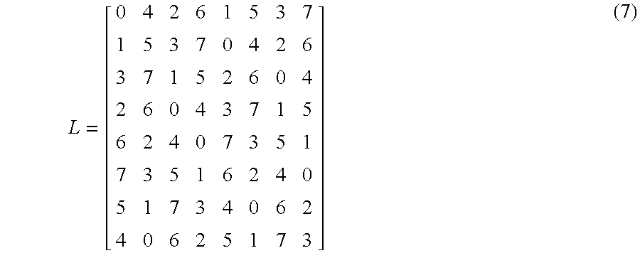
  • the procedure LatinSquare (List ⁇ (0), ⁇ (1), . . . , ⁇ (n ⁇ 1) ⁇ ) may be used to construct the Latin square for a baseline network. For example, for an 8 ⁇ 8 network, by Corollary 3, the first row, ⁇ (0), ⁇ (1), . . . , ⁇ (n ⁇ 1), may be computed, which is 0,4,2,6,1,5,3,7. LatinSquare may then be called to generate the rest n ⁇ 1 rows of the Latin square shown in (7).

Abstract

Systems and methods are presented to achieve crosstalk-free all-to-all exchange in optical multistage self-routing networks. The approach involves the computation of a Latin square and the subsequent decomposition of its rows to semi-permutations. Processors may then send messages to other processors in accord with these semi-permutations.

Description

STATEMENT REGARDING FEDERALLY SPONSORED RESEARCH OR DEVELOPMENT
This invention was made with Government support under Grant No. DAAH 04-96-1-0234, awarded by the U.S. Army Research Office, and Grant No. OSR-935-0540, awarded by the National Science Foundation. The Government has certain rights in this invention.
FIELD OF THE INVENTION
This application relates to the field of parallel computing and networking, and more specifically to all-to-all personalized exchange in multistage networks.
BACKGROUND OF THE INVENTION
Communication among processors may be a design issue when, for example, a parallel processing system is built, or a parallel procedure is designed. With advances in silicon and Ga—As technologies, processor speed may soon reach the gigahertz (GHz) range. Traditional metal-based communication technology used in parallel computing systems is becoming a potential bottleneck. Progress in the traditional interconnects, or to in the new interconnect technologies, such as optics, would be well received in the parallel computing systems community.
Advances in electro-optic technologies have made optical communication a promising networking choice to meet the increasing demands for high channel bandwidth and low communication latency of high-performance computing/communication applications. Fiber optic communications offer a combination of high bandwidth, low error probability, and gigabit transmission capacity. They have been extensively used in wide-area networks and have received much attention in the parallel processing community as well. In fact, many commercial, massively parallel computers, such as the Cray C90, use optical technology in their communication subsystems.
Using new optical technologies in parallel computers may require us to reexamine the design of interconnection networks, and use of parallel processing procedures. Exploring the capabilities of the optical technology may involve a careful analysis of the properties of optics, a proposal of new performance measures, a design of new interconnection networks and routing procedures, and new parallel processing application procedures.
Multistage interconnection networks (MINs), hereafter also referred to as multistage networks, have been used for interconnecting purposes in parallel computing systems. A MIN can be blocking, such as a Banyan network, rearrangeably non-blocking, such as a Benes network, non-blocking, such as crossbar. Additionally, a MIN may have variably connecting capabilities, from rearrangeable for permutation to non-blocking for multicast, such as in a Clos-network, depending on the number of stages, the number of switches, the switch capability, and the interconnection patterns used between stages.
As optical technology advances, there has been a growing interest in using optical technology for implementing interconnection networks and switches. Although electronic MINs and optical MINs have many similarities, here are some fundamental differences between them. Because of some unique properties of optics, traditional routing procedures and results may not be applicable here. New research addressing optical MINs may be useful.
In the communication pattern known as all-to-all personalized exchange, every processor in a processor group sends a distinct message to every other processor in the group. All-to-all personalized exchange occurs in many important parallel computing/networking applications, such as matrix transposition and fast Fourier transform (FFT).
The issue of realizing all-to-all personalized exchange in optical multistage networks is examined below. A basic element of optical switching networks is a directional coupler with two inputs and two outputs (hereafter referred to simply as switches). Depending on the control voltage applied to it, an input optical signal is coupled to either of the two outputs, setting the switch to either the parallel or the crossing state. A class of topologies that can be used to construct optical networks is multistage interconnection networks (MINs), which interconnect their inputs and outputs via several stages of switches.
Advances in electro-optic technologies have made optical communication a promising networking choice to meet the increasing demands for high channel bandwidth and low communication latency of high-performance computing/communication applications. Although optical multistage networks hold great promise and have demonstrated advantages over their electronic counterpart, they also introduce new challenges such as how to deal with the unique problem of avoiding crosstalk in the optical switches, which may occur when two signal channels in a switch interact with each other.
There are two ways in which optical signals can interact in a planar switching network. The channels carrying the signals may cross each other in order to embed a particular topology. Alternatively, two paths sharing a switch may experience some undesired coupling from one path to another within a switch. It would be desirable to achieve optical exchange in multistage networks in a manner that reduces crosstalk.
SUMMARY OF THE INVENTION
Methods and systems are presented below involving optical multistage interconnection networks (MiNs). Although optical MINs hold great promise and have demonstrated advantages over their electronic counterparts, they also present their own problems. Due to certain optical properties, crosstalk in optical switches should be avoided if they are to work efficiently. The concept of a semi-permutation is introduced to analyze the permutation capability of optical MINs under the constraint of avoided crosstalk in several types of MINs. In particular, an optimal scheme for realizing crosstalk-free all-to-all personalized exchange in a class of unique-path, self-routing optical multistage networks is presented.
The basic idea of realizing all-to-all personalized exchange in such a multistage network is to transform it to a collection of the above-mentioned semi-permutations. Each of the semi-permutations can be realized crosstalk-free in a single pass (i.e., in a single, concurrent exchange of signals) and can take advantage of pipelined message transmission in consecutive passes.
More specifically, a method for crosstalk-free all-to-all exchange in an optical multistage network having inputs and outputs coupled to processors is presented. The method comprises sending messages between the processors in multiple passes, wherein, in each of the multiple passes, each of the processors transmits, in one-to-one fashion, a message to one of the processors by way of the inputs and outputs, in accord with semi-permutations decomposed from permutations corresponding to rows of a matrix. The optical multistage network may be one of a baseline network, omega network, Banyan network, and their reverse networks.
In each of the multiple passes, each of the processors may transmit, in one-to-one fashion, a message to one of the processors by way of the inputs and outputs, in accord with semi-permutations decomposed from permutations corresponding to rows of a Latin square. The semi-permutations may be obtained by computing two input sets.
A method is also presented for crosstalk-free all-to-all exchange in an optical multistage network having n inputs and n outputs coupled to n processors, where n ε{2, 4, 8, 16, . . . } and wherein each of the n processors is connected to one of the n inputs and one of the n outputs, comprising computing a Latin square having n rows and n columns; associating the n rows with n admissible permutations, each of the n admissible permutations being a one-to-one mapping from N={0,1, . . . ,n−1} to itself; for j a member of the set {1, 2, . . . , n}, decomposing a jth permutation, from among the n admissible permutations, into two semi-permutations, one of the two semi-permutations, s(j), being a restriction of said mapping to a subset, S(j), of N having n/2 elements, and another of the two semi-permutations, t(j), being a restriction of said mapping to a subset, T(j), of N where T(j) is a complement N\S(j); sending n/2 messages in a (2j−1)th pass, and n/2 messages in a (2j)th pass, each of the messages departing from one of the n processors, traveling through one of the n inputs and one of the n outputs, and arriving at one of the n processors, wherein a kth processor from among the n processors sends a message to an Ith processor from among the n processors in the (2j-1)th pass if, and only if, s(j)(k)=1, and a qth processor from among the n processors sends a message to an rth processor from among the n processors in the (2j)th pass if, and only if, t(j)(q)=r, and for different j=1, . . . ,n, repeating said step of decomposing a jth permutation from among the n admissible permutations until all of the n admissible permutations have been decomposed; for different j=1, . . . ,n, repeating the step of sending n/2 messages in a (2j−1)th pass, and n/2 messages in a (2j)th pass until n2 messages have been sent, and 2n passes have occurred, corresponding to 2n decompositions of the n admissible permutations.
Computing a Latin square having n rows and n columns may include computing a Latin square off-line. The optical multistage network may be one of a baseline network, omega network, Banyan network, and their reverse networks. The optical multistage network may include m=log2 n stages, each having one switch with two switch settings, interspersed by m−1 interstage links, wherein computing a Latin square may include computing a Latin square so that each of the n rows corresponds, in one-to-one fashion, with a configuration of switch settings. The method may further comprise composing each of the n admissible permutations as a composition of 2m−1 permutations, a jth permutation from among the n admissible permutations composed as
σ(j) m−1π(j) m−2σ(j) m−2 . . . π(j) 0σ(j) 0,
such that to each of the m stages there is associated a stage permutation and to each of the m−1 interstage links there is associated an interstage link permutation, where the stage permutation corresponding to the jth permutation from among the n admissible permutations, and associated with an ith stage is denoted by σ(j) i, with i=1, . . . , m, and the interstage link permutation corresponding to the jth permutation from among the n admissible permutations, and associated with an ith interstage link is denoted by π(j) i, with i=1, . . . , m−1.
Also presented below is a method of achieving all-to-all crosstalk-free exchange in an optical multistage network, said network having an even number, n≧2, of processors, comprising computing an n×n matrix [ a 0 , 0 a 0 , 1 a 0 , n - 1 a 1 , 0 a 1 , 1 a 1 , n - 1 a n - 1 , 0 a n - 1 , 1 a n - 1 , n - 1 ]
Figure US06567858-20030520-M00001
such that each entry of the matrix is chosen from the set N={0,1, . . . , n−1}, and such that the members of each row equals the set N, and the members of each column equals the set N; mapping the matrix to a column vector of permutations, [ ρ ( 0 ) ρ ( 1 ) ρ ( n - 1 ) ]
Figure US06567858-20030520-M00002
where a jth entry of the column vector of permutations, ρ(j), is given by ( 0 1 2 n - 1 a j , 0 a j , 1 a j , 2 a j , n - 1 ) ;
Figure US06567858-20030520-M00003
decomposing each permutation, ρ(j), into two semi-permutations, s(j), and t(j), each of which can be realized crosstalk-free, given by s ( j ) = ( b j , 0 b j , 1 b j , n / 2 - 1 c j , 0 c j , 1 c j , n / 2 - 1 ) and t ( j ) = ( d j , 0 d j , 1 d j , n / 2 - 1 e j , 0 e j , 1 e j , n / 2 - 1 ) ,
Figure US06567858-20030520-M00004
where s(j) is a restriction of the permutation ρ(j) to a subset, S(j), of N having n/2 elements, and t(j) is a restriction of the permutation ρ(j) to a subset, T(j), of N where T(j) is a complement N\S(j); in a first pass, sending messages from processor b0j to processor c0j for j=0, . . . , n/2−1; in a second pass, sending messages from d0j to processor e0j for j=0, . . . , n/2−1; in a third pass, sending messages from processor b1j to processor c1j for j=0, . . . , n/2−1; and in a fourth pass, sending messages from d1j to processor e1j for j=0, . . . , n/2−1.
Also presented below is a method of achieving all-to-all crosstalk-free exchange in an optical multistage network, said network having an even number, n≧2, of processors, comprising computing an n×n matrix [ a 0 , 0 a 0 , 1 a 0 , n - 1 a 1 , 0 a 1 , 1 a 1 , n - 1 a n - 1 , 0 a n - 1 , 1 a n - 1 , n - 1 ]
Figure US06567858-20030520-M00005
such that each entry of the matrix is chosen from the set N={0,1, . . . , n−1}, and such that the members of each row equals the set N, and the members of each column equals the set N; mapping the matrix to a column vector of permutations [ ρ ( 0 ) ρ ( 1 ) ρ ( n - 1 ) ]
Figure US06567858-20030520-M00006
where a jth entry of the column vector of permutations, ρ(j), is given by ( 0 1 2 n - 1 a j , 0 a j , 1 a j , 2 a j , n - 1 ) ;
Figure US06567858-20030520-M00007
decomposing each permutation, ρ(j), into two semi-permutations, s(j), and t(j), each of which can be realized crosstalk-free, given by s ( j ) = ( b j , 0 b j , 1 b j , n / 2 - 1 c j , 0 c j , 1 c j , n / 2 - 1 ) and t ( j ) = ( d j , 0 d j , 1 d j , n / 2 - 1 e j , 0 e j , 1 e j , n / 2 - 1 ) ,
Figure US06567858-20030520-M00008
where s(j) is a restriction of the permutation ρ(j) to a subset, S(j), of N having n/2 elements, and t(j) is a restriction of the permutation ρ(j) to a subset, T(j), of N where T(j) is a complement N\S(j); in a (2i−1)th pass, sending messages from processor bi−1, j to processor ci−1, j for j=0, . . . , n/2−1, for i=1, . . . , n; in a (2i)th pass, sending messages from di−1, j to processor ei−1, j for j=0, . . . , n/2−1, for i=1, . . . , n.
A system for all-to-all crosstalk-free exchange is also presented below that includes an optical multistage network associated with a Latin square having n columns and n rows, wherein the optical multistage network includes an even number, n≧2, of processors coupled to said processors; instructions for said processors to associate the n rows with n admissible permutations, each of the n admissible permutations being a one-to-one mapping from N={0,1, . . . , n−1} to itself; for j a member of the set {1, 2, . . . , n}, instructions for said processors to decompose a jth permutation from among the n admissible permutations into two semi-permutations, one of the two semi-permutations, s(j), being a restriction of said mapping to a subset, S(j), of N having n/2 elements, and another of the two semi-permutations, t(j), being a restriction of said mapping to a subset, T(j), of N where T(j) is a complement N\S(j); instructions for said processors to initiate the transmittal of n/2 messages in a (2j−1)th pass, and n/2 messages in a (2j)th pass, each of the messages departing from one of the n processors, traveling through one of the n inputs and one of the n outputs, and arriving at one of the n processors, wherein a kth processor from among the n processors sends a message to an Ith processor from among the n processors in the (2j−1)th pass if. and only if, s(j)(k)=1, and a qth processor from among the n processors sends a message to an rth processor from among the n processors in the (2j)th pass if, and only if, t(j)(q)=r; and for different j=1, . . . , n, instructions for said processors to continue to decompose a jth permutation from among the n admissible permutations until all of the n admissible permutations have been decomposed; and for different j=1, . . . , n, instructions for said processors to continue to send n/2 messages in a (2j−1)th pass, and n/2 messages in a (2j)th pass until n2 messages have been sent, and 2n passes have occurred, corresponding to 2n decompositions of the n admissible permutations.
The optical multistage network may include one of a Banyan network, an omega network, a baseline network, and their reverse networks. The instructions for the processors to decompose a jth permutation from among the n admissible permutations into two semi-permutations may include computing two input sets in a time of the order O(n).
A system for crosstalk-free all-to-all exchange in an optical multistage network is also presented that comprises processors; and instructions for said processors to send messages between the processors in multiple passes, wherein, in each of the multiple passes, each of the processors transmits, in one-to-one fashion, a message to one of the processors in accord with semi-permutations decomposed from permutations corresponding to rows of a matrix. The matrix may be a Latin square.
The instructions for said processors to send messages between the processors may include instructions to compute input sets from which the semi-permutations may be obtained in a time on the order of O(n) where the Latin square is an n×n matrix. Instructions may be included to compute two input sets from which the semi-permutations may be obtained.
BRIEF DESCRIPTION OF THE DRAWINGS
The following figures depict certain illustrative embodiments of the invention in which like reference numerals refer to like elements. These depicted embodiments are to be understood as illustrative of the invention and not as limiting in any way.
FIG. 1 shows three examples of multistage networks of the prior art;
FIG. 2 shows examples of semi-permutations that can and cannot be realized in an 8×8 baseline network;
FIG. 3 shows a routing example in an 8×8 baseline network;
FIG. 4 shows an example of basic permutations for an 8×8 mapping;
FIG. 5 shows all of the possible switch settings in which each stage is set to either parallel or crossing in an 8×8 baseline network;
FIG. 6 (FIGS. 6A and 6B) shows all crosstalk-free routings corresponding to the semi-permutations decomposed from the permutations which form a Latin square in an 8×8 baseline network;
FIG. 7 shows the odd-even list of numbers 0, 1, . . . , 2k−1for k=3;
FIG. 8 shows the 3-bit Gray code sequence generated in one embodiment by applying basic permutations.
FIG. 9 shows a flow chart indicating some steps for achieving crosstalk-free, all-to-all exchange.
FIG. 10 shows an embodiment of the present invention involving teleconferencing.
DETAILED DESCRIPTION OF THE PREFERRED EMBODIMENTS
To provide an overall understanding of the invention, certain methods, systems and devices will be discussed with reference to all-to-all exchange in baseline networks. However, it will be understood by persons of ordinary skill in the art that the general methods, systems and devices described herein are equally applicable to other types of networks in which all-to-all crosstalk-free exchange is desired.
A semi-permutation, which is a decomposition of a mathematical permutation (a more precise definition appears below), may be introduced as a useful tool for designing crosstalk-free routing in an optical multistage network in a manner described below. Herein, the properties of semi-permutations in the context of crosstalk-free routing are explored, and all-to-all personalized exchange procedures in optical multistage networks based on crosstalk-free semi-permutations are developed. In general, realizing all-to-all personalized exchange in an optical multistage network involves associating multistage networks with multiple semi-permutations each of which can be realized crosstalk-free in a single pass, and taking advantage of pipelined message transmission in consecutive passes.
Referring to FIG. 1, an 8×8 baseline network 11, an omega network 12, and a Banyan network 13 are shown. Each network includes network inputs 16 and outputs 17, and interstage links 14, and stages 15.
A permutation is a one-to-one mapping between the network inputs and outputs. Any permutation may be realized in a Benes network in a single pass (in the electronic version), and any permutation can be realized in a Benes network in two passes crosstalk-free (in the optical version). However, the switch setting in a Benes network is complex and expensive, which may discourage people to choose this type of network for a high speed communication environment. Moreover, a full permutation capability may not be necessary for all-to-all personalized exchange. Herein, a class of unique-path, self-routing multistage networks such as baseline 11, omega 12, Banyan 13 networks, and their reverse networks are considered. A typical network structure for this class has n(=2nt) inputs 16 and outputs 17 and log2 n=m stages 15, with each stage consisting of n/2 2×2 switches, and any two adjacent stages connected by n interstage links 14.
A baseline network 11, an omega network 12, and a Banyan network 13 are examples of network configurations that have several advantages. These networks, for example, impose less hardware cost (almost half of that of a Benes network), and have fast switch settings (self-routing) at the stages 15. On the other hand, the limitations of networks such as a baseline network 11, an omega network 12, and a Banyan network 13 are that not every permutation is admissible to such a network, and not every admissible permutation to the network can be decomposed to semi-permutations which, can be realized in a single pass crosstalk-free in the network. However, such limitations do not prohibit us to find some special permutations and semi-permutations which can be used for efficiently realizing all-to-all personalized exchange in such networks. Such message exchanges initiate at processors (not shown in FIG. 1) each of which may be connected to one input and one output (eight inputs 16 and eight outputs 17 are shown in FIG. 1.). The message proceeds from one of the inputs 16, through one of the stages 15 and one of the interstage links 14, then through more stages IS and interstage links 14, in alternating fashion, until the message exits through one of the network outputs 17. From the network outputs, the message arrives at a processor.
A permutation is a one-to-one mapping between the network inputs and outputs.
For an n×n network, suppose there is a one-to-one mapping ρ which maps input i to output ai(i.e., ρ(i)=ai)aiε{0, 1, . . . , n−1} for 0≦i≦n−1, and ai≠aj. Let ρ = ( 0 1 n - 1 a 0 a 1 a n - 1 )
Figure US06567858-20030520-M00009
denote this permutation. In particular, when ρ(i)=i for 0≦n−1, this permutation is referred to as an identity permutation and is denoted by I. A permutation which is realizable by the multistage network is referred to as an admissible permutation of the network.
Given two permutations ρ1and ρ2, a composition ρ1ρ2 of the two permutations is also a permutation, which maps i to ρ12(i)). Clearly, ρI=Iρ=ρ, but in general ρ1ρ2≠ρ2ρ1. However, the associative law does apply here. That is, ρ12ρ3)=(ρ1ρ23. (Let ρi denote the composition of i permutations ρ's. Also, if ρ1ρ2=I,ρ1 is referred to as the inverse of ρ2 and vice versa, ρ12 −1and ρ21 −1. In addition, for representational convenience, the following notation is used to represent a mapping ρ(a)=b a ρ b
Figure US06567858-20030520-M00010
When realizing a permutation in an optical multistage network in a single pass, as discussed earlier, switches suffer crosstalk. Semi-permutations may be introduced as a useful tool for crosstalk-free routing in an optical multistage network consisting of 2×2 switches.
Given an even integer n, a semi-permutation is defined as a one-to-one mapping between some n/2 inputs {x0, x1, . . , xn/2−1} and some n/2 outputs {(y0,y1, . . . , yn/2−1} satisfying { x 0 2 , x 1 2 , , x n 2 - 1 n , } = { y 0 2 , y 1 2 , , y n 2 - 1 2 , } = { 0 , 1 , , n 2 - 1 } ( 1 )
Figure US06567858-20030520-M00011
where xi,yiε{0, 1, . . . ,n−1}, yi≠yj for 0≦i≠j≦n/2−1, and x0<x1< . . . <xn/2−1. The semi-permutation is denoted by s = ( x 0 x 1 x n 2 - 1 y 0 y 1 y n 2 - 1 ) , ( 2 )
Figure US06567858-20030520-M00012
and the input set
{x 0 ,x 1 , . . . , x n/2−1}
is denoted by InputSet(s) and the output set
{y 0 ,y 1 , . . . , y n/2−1}
is denoted by OutputSet(s). For example, for n=8, the following one-to-one mapping ( 0 3 4 6 1 5 3 7 )
Figure US06567858-20030520-M00013
is a semi-permutation since { 0 2 , 3 2 , 4 2 , 6 2 } = { 0 , 1 , 2 , 3 } , and { 1 2 , 5 2 , 3 2 , 7 2 } = { 0 , 2 , 1 , 3 } = { 0 , 1 , 2 , 3 } .
Figure US06567858-20030520-M00014
A semi-permutation is a partial permutation that ensures that there is only one active link passing through each input switch and output switch. The use of semi-permutations helps eliminate crosstalk in the first and last stages in the network, Thus, semi-permutations may be realized in an optical network crosstalk-free. To ensure that the entire network is crosstalk-free, signals must travel crosstalk-free through the switches in the intermediate stages as well.
The following result regarding the relationship between permutations is useful.
Theorem 1. Any permutation can be decomposed into two semi-permutations.
The proof, together with an efficient decomposition procedure, may be found in Y. Yang, J. Wang, and Y. Pan, Permutation Capability of Optical Multistage Interconnection Networks, Proc. of 12th IEEE International Parallel Processing Symposium, Orlando, Fla., March 1998, pp. 125-133. There might be multiple different decompositions from a single permutation. However, for a permutation which is realizable in a multistage network, there may not exist a decomposition for the permutation such that the resulting semi-permutations are realizable in the network crosstalk-free.
Given two semi-permutations decomposed from a permutation, one semi-permutation is referred to as the twin of the other. Let the two semi-permutations be s and t, respectively. Then
InputSet(s)∪InputSet(t)OutputSet(s)∪OutputSet(t)={0, 1, . . . , n−1}.
If a semi-permutation can be realized in a multistage network in a single pass crosstalk-free, it is referred to as a crosstalk-free semi permutation for this network. In FIG. 2, examples of semi-permutations for an 8×8 baseline network are depicted. Paths 21 show that ( 0 2 4 6 3 5 7 1 )
Figure US06567858-20030520-M00015
is a crosstalk-free semi-permutation for the network; paths 25, on the other hand, show that the semi-permutation ( 0 2 5 6 4 6 0 2 )
Figure US06567858-20030520-M00016
cannot be realized in a single pass crosstalk-free. In paths 21, each switch supports one, and only one, path. Paths 25 do not represent a crosstalk-free semi-permutation because two switches support two paths each, while two other switches support no paths. The bold boxes 26 and 27 indicate the two switches with crosstalk.
Lemma 1. For the two semi-permutations decomposed from an admissible permutation of a multistage network, if one is crosstalk-free for the network, so is the other.
Proof. Let the two semi-permutations be s1 and s2, respectively. Suppose s1 is crosstalk-free for an n×n multistage network, but s2 is not. Thus, there exist two paths, among the n/2 paths of s2 in the network, which go through the same switch in some intermediate stage in the network. This implies that none of the n/2 paths of its twin, s1, goes through this switch. Since there are n/2 switches in each stage of the network, there must be two paths of s1 that go through a single switch in that stage, which contradicts that s1 is crosstalk-free for the network.
From paths 21, the twin semi-permutation ( 1 3 5 7 6 0 2 4 )
Figure US06567858-20030520-M00017
is also crosstalk-free for the network. A decomposition of a permutation is called a crosstalk-free decomposition to a multistage network if its semi-permutations are crosstalk-free realizable to the network.
The concept of composition of permutations to semi-permutations may also be extended. Given two semi-permutations s1 and s2 with InputSet(s1)=OutputSet(s2), a composition s1s2 is defined as the mapping that i is mapped to s1(s2(i)) for i εInputSet(s2). The composition of two semi-permutations s1 and s2 is also a semi-permutation with the input set being InputSet(s2) and the output set being OutputSet(s1). The composition of more than one semi-permutation may be defined iteratively. Let s1s2 be a composition of two semi-permutations s1 and s2, and let s3 be the third semi-permutations satisfying InputSet(s1s2)=OutputSet(s3), i.e., InputSet(s2)=OutputSet(s3), then s1s2s3 is a composition defined as (s1s2)s3 with the input set being InputSet(s3) and the output set being OutputSet(s1). It can be verified that the associate law holds for the composition operation, that is, (s2)s3=s1(s2s3).
In the context of a multistage network, each stage and each interstage link in the network may be viewed as a shorter n×n network. Let σi(0≦i≦m−1) denote the permutation represented by stage i, and πi(0≦i≦m−2) denote the permutation represented by the set of interstage links between stage i and stage i+1. The permutation σi, and the permutation πi are known as a stage and an interstage permutation, respectively. An admissible permutation of a multistage network can be expressed by a composition of stage permutations and interstage permutations. For example, an admissible permutation of a baseline network can be expressed as
σm−1πm−2σ−2 . . . π0σ0  (3)
In general, interstage permutations πi's are fixed by the network topology. For a baseline network, suppose the binary representation of a number a ε{0,1, . . . , n−1} is p m−1pm−2 . . . p1p0. Then permutation πi represents the following mapping p m - 1 p m - 2 p 1 p 0 π i p m - 1 p m - 2 p m - i p 0 p m - i - 1 p 2 p 1 ( 4 )
Figure US06567858-20030520-M00018
This mapping corresponds to a 1-bit circular right-shift among the nt−i least significant bits while keeping the i most significant bits unchanged. However, stage permutation σ1's are not fixed since each switch can be set to either parallel or crossing.
Referring to FIG. 3, each switch is set to a parallel configuration 31 or a crossing configuration 32. Stage permutations 33 include σ0, σ1 and σ2 which correspond to the permutations with only the second switch set to crossing, only the first and third switches set to crossing, and all four switches set to crossing, respectively: σ 0 = ( 0 1 2 3 4 5 6 7 0 1 3 2 4 5 6 7 ) , σ 1 = ( 0 1 2 3 4 5 6 7 1 0 2 3 5 4 6 7 ) , σ 2 = ( 0 1 2 3 4 5 6 7 1 0 3 2 5 4 7 6 )
Figure US06567858-20030520-M00019
and interstage permutations 34 (in both binary and decimal) π 0 = ( 000 001 010 011 100 101 110 111 000 100 001 101 010 110 011 111 ) = ( 0 1 2 3 4 5 6 7 0 4 1 5 2 6 3 7 ) π 1 = ( 000 001 010 011 100 101 110 111 000 010 001 011 100 110 101 111 ) = ( 0 1 2 3 4 5 6 7 0 2 1 3 4 6 5 7 )
Figure US06567858-20030520-M00020
For input 0, the following transformation may be obtained
0 σ 4 0 π 4 0 σ 1 1 π 1 2 σ 2 3
Figure US06567858-20030520-M00021
that is, 0 σ 2 π 1 σ 1 π 0 σ 0 3
Figure US06567858-20030520-M00022
After computing the transformation for every input, the overall permutation for the switch settings in the network may be obtained σ 2 π 1 σ 1 π 0 σ 0 = ( 0 1 2 3 4 5 6 7 3 7 5 1 0 4 2 6 )
Figure US06567858-20030520-M00023
Notice that not every permutation is admissible to a multistage network like baseline, omega, Banyan and their reverse network. Also, not every admissible permutation of the network has a crosstalk-free decomposition, for which a counterexample is provided below. However, the following Lemma specifies the conditions of existence of a crosstalk-free decomposition from an admissible permutation.
Lemma 2 Let an admissible permutation of a multistage network shown in (3) be denoted by ρ2m−1ρ2m−2 . . . ρ2ρ1. The admissible permutation can be decomposed into two crosstalk-free semi-permutations if and only if permutation ρi can be decomposed into two semi-permutations si and ti for 1≦2m−1 such that
InputSet(s 2m−1)=OutputSet(s 2m−2)
InputSet(s 2m−2)=Output(Set(s m−3)
  . . .
InputSet(s 2)=OutputSet(s 1)  (5)
The two crosstalk-free semi-permutations obtained are s2m−1s2m−2 . . . s2s1 and t2m−1t2m−2 . . . t2t1, respectively.
Proof. If ρi can be decomposed to si and ti for 1≦i≦2m−1 and satisfy (5), then s2m−1s2m−2 . . . s2s1 form a composition of these semi-permutations. That is, given any kεInputSet(s1), it can be mapped by s1 to s1(k)εOutputSet(s1)=InputSet(s2), then mapped by s2 to s2s1(k)εOutputSet(s2)=InputSet(s3), . . . , and finally mapped by s2m−1 to s2m−1s2m−2 . . . s2s1(k)εOutputSet(s2m−1). Since each s1 is a semi-permutation and any input set and output set of a semi-permutation satisfy (1), no two such paths from InputSet(s1) to OutputSet(s2m−1) pass the same switch in the network, and thus si is crosstalk-free. The same conclusion can be drawn for t2m−1t2m−2 . . . t2t1. Also, the composition s2m−1s2m−2 . . . s2s1 and the composition t2m−1t2m−2 . . . t2t1 are semi-permutations with the input set InputSet(s1) and InputSet(t1), and the output set OutputSet(s2m−1) and OutputSet(t2m−1), respectively. Therefore, the admissible permutation is decomposed into two crosstalk-free semi-permutations s2m−1s2m−2 . . . s2s1 and t2m−1t2m−2 . . . t2t1.
On the other hand, if the admissible permutation can be decomposed to two crosstalk-free semi-permutations, si may be constructed from ti from i=1 to 2m satisfying (5).
An approach to realizing all-to-all personalized exchange in multistage networks without the constraint of crosstalk-free, i.e., in (ordinary) electronic multistage networks, may be introduced. The approach may then be extended to realize all-to-all personalized exchange in optical multistage networks under the constraint of crosstalk-free.
Given n processors and an n×n multistage network, let processor i (0≦i≦n−1) be connected to input i and ouput i of the network to other processors and receive messages from other processors through output i of the network.
The following lemma concerning a bound on the maximum communication delay of all-to-all personalized exchange in a multistage network holds.
Lemma 3 The maximum communication delay of all-to-all personalized exchange in an all n x n network of log n stages is at least Ω(n+log n).
Proof. The lemma holds because each processor receives one message from all other n−1 processors, which takes Ω(n) time, and each message goes through log n stages from its source processor to its destination processor, which takes Ω(log n) time.
A Latin square is defined as an n×n matrix [ a 0 , 0 a 0 , 1 a 0 , n - 1 a 1 , 0 a 1 , 1 a 1 , n - 1 a n - 1 , 0 a n - 1 , 1 a n - 1 , n - 1 ]
Figure US06567858-20030520-M00024
in which the entries aij's are numbers in {0, 1, 2, . . . n−1} and no two entries in a row (or a column) have the same value.
Now suppose that each row in the Latin square, ai0,ai1, . . . , ai,n−1 corresponds to a permutation ( 0 1 2 n - 1 a i , 0 a i , 1 a i , 2 a i , n - 1 ) ,
Figure US06567858-20030520-M00025
which is admissible to an n×n self-routing multistage network. By realizing the n admissible permutations corresponding to the Latin square, all-to-all personalized exchange may be achieved.
That every message has the same length, so that the message transmission at each stage is synchronized, may be assumed. If the messages are not synchronized, then one may make them effectively synchronized. This may be done by forcing messages that take shorter than the maximum time needed to transmit a message to wait the difference. A higher-level description of the procedure ATAPE is given in Table I.
In procedure ATAPE, processor j sends distinct messages to all destinations in the order of a0j,a1j, . . . , an−1j, which corresponds to the column j of the Latin square. On the other hand, in time frame i, all n processors send their messages simultaneously to destinations ai,0,ai,1, . . . , ai,n−1, which corresponds to the row i, of the Latin square. Thus, in procedure ATAPE all-to-all personalized exchange is achieved by realizing n permutations which correspond to the n rows of the Latin square, since under the assumption that each permutation represented by a row of the Latin square is admissible to the network.
Note that the network under consideration is a self-routing network, where each switch is set automatically by the routing tag contained in the message passing that switch. Since admissible permutations are being considered, at any time two messages entering from the two inputs of a switch can pass the switch simultaneously without any conflicts. In addition, once the previous n messages leave the switches of the cUrrent stage, the next n messages can enter the switches of this stage. Thus, the sequential steps of 2.1 are actually performed in a pipelined fashion, which achieves a form of parallelism. Therefore, the time complexities of Step 1 and Step 2 are O(n) and O(n+log n), respectively. The total time delay for all-to-all personalized exchange procedure is O(n+log n), which generally matches the low bound of the communication delay for this type of network.
Now, consider realizing all-to-all personalized exchange in optical networks under the constraint of crosstalk-free. If each admissible permutation to the network can be decomposed to two crosstalk-free semi-permutations, the all-to-all personalized exchange in an optical multistage-network can be achieved by realizing these 2n semi-permutations in the network. The total delay is about twice that of the electronic counterpart. Since this process can still be performed in a pipelined fashion, the proposed all-to-all personalized exchange procedure achieves optimal communication delay for optical multistage networks as well.
TABLE I
All-to-all personalized exchange procedure for a class of multistage
networks
Procedure ATAPE
begin
Step 1. for each processor j (0 ≦ j ≦ n-1) do in parallel
  1.1 for each αij (0 ≦ i ≦ n-1) in the Latin square do in sequential
    prepare a personalized message from processor j to processor αij;
    insert the message into the message queue j;
Step 2. for each processor j (0 ≦ j ≦ n-1) do in parallel
  2.1 for each message with destination address αij (0 ≦ i ≦ n-1) in the
  message queue j do in sequential
    send message destined to αij through input j of the network;
end;
Not all permutations are admissible in a baseline network. However, in the following, a simple method is described for choosing a special set of permutations, which are admissible to a self-routing multistage network and can form a Latin square.
First, a set of basic permutations used for constructing a Latin Square is introduced. For an n×n mapping, where n=2m, m basic permutations φi (1≦i ≦m) may be defined as follows. Let the binary representation of a number αε{0, 1, . . . , n−1} be pm−1pm−2 . . . p1p0. Then p m - 1 p m - 2 p i p i - 1 p i - 2 p 1 p 0 φ i p m - 1 p m - 2 p i p i - 1 p i - 2 p 1 p 0 ( 6 )
Figure US06567858-20030520-M00026
The permutation φi is actually the operation flipping the ith bit of a binary number. For example, the three basic permutations for n=8 are the mapping φ 1 = ( 0 1 2 3 4 5 6 7 1 0 3 2 5 4 7 6 ) , φ 2 = ( 0 1 2 3 4 5 6 7 2 3 0 1 6 7 4 5 ) , φ 3 = ( 0 1 2 3 4 5 6 7 4 5 6 7 0 1 2 3 ) ,
Figure US06567858-20030520-M00027
which are shown in FIG. 4. The first permutation corresponds to the φ1 basic permutation 41, the second permutation to the φ2 basic permutation 42, and the third permutation to the φ3 basic permutation. Each arc in FIG. 4 represents a mapping between two numbers.
In describing the construction of all-to-all personalized exchange Latin square in the following, interest especially lies in φ1. Other φ1's are used in the proof in the appendix. The stage permutation of a stage in the network is φ1 if and only if the switches in this stage are all set to crossing, and the stage permutation of a stage in the network is I if and only if the switches in this stage are all set to parallel.
Theorem 2 Let the stage permutation of each stage in a baseline network take either φ1 or I, The admissible permutations corresponding to all possible such switch settings form a Latin square.
Proof. See Appendix.
In FIG. 5, all possible such switch settings in an 8×8 baseline network are listed. Each of the eight routing patterns corresponds to a row of the Latin square L, where: L = [ 0 4 2 6 1 5 3 7 1 5 3 7 0 4 2 6 3 7 1 5 2 6 0 4 2 6 0 4 3 7 1 5 6 2 4 0 7 3 5 1 7 3 5 1 6 2 4 0 5 1 7 3 4 0 6 2 4 0 6 2 5 1 7 3 ] ( 7 )
Figure US06567858-20030520-M00028
Thus, routing pattern 51 has switch settings I, I, and I in columns one, two, and three respectively and corresponds to the first row of the Latin square L; the routing pattern 52 has switch settings I,I, and φ1 in columns one, two, and three respectively and corresponds to the second row of the Latin square L; the routing pattern 53 has switch settings I, φ1, and φ1 in columns one,two, and three respectively and corresponds to the third row of the Latin square L; the routing pattern 54 has switch settings I, φ1, and I in columns one, two, and three respectively and corresponds to the fourth row of the Latin square L; the routing pattern 55 has switch settings φ1, φ1, and I in columns one, two, and three respectively and corresponds to the fifth row of the Latin square L; the routing pattern 56 has switch settings φ11, and φ1 in columns one, two, and three respectively and corresponds to the sixth row of the Latin square L; the routing pattern 57 has switch settings φ1. I, and φ1 in columns one, two, and three respectively and corresponds to the seventh row of the Latin square L; and the routing pattern 58 has switch settings φ1, I, and I in columns one, two, and three respectively and corresponds to the eighth row of the Latin square L.
The same conclusions as in Theorem 2 for other self-routing multistage networks, such as omega and Banyan networks, may be drawn.
Not every admissible permutation to the network can be decomposed into semi-permutations which can be realized in the network crosstalk-free. For example, the permutation ( 0 1 2 3 4 5 6 7 2 4 0 6 1 5 3 7 )
Figure US06567858-20030520-M00029
is admissible to an 8×8 baseline network. However, this permutation does not have a crosstalk-free decomposition. In fact, applying the decomposition procedure to this permutation, a unique decomposition of semi-permutations may be obtained: ( 0 2 5 7 2 0 5 7 ) and ( 1 3 4 6 4 6 1 3 )
Figure US06567858-20030520-M00030
However, it can be verified that none can pass the network crosstalk-free.
However, it can be proved that any permutation in the special set of admissible permutations, which forms a Latin square as described above, does have a crosstalk-free decomposition of semi-permutations. Thus, all-to-all personalized exchanged can be realized in 2n passes in an n×n self-routing optical multistage network crosstalk-free.
Given a semi-permutation s as in (2), if the input set {x0, x1 , . . . xa/2−1} and the output set {y0, y1 . . . , ya/2−1} are equal, the semi-permutation is said to be self-mapping, if the intersection of the two sets is empty (in other words, the union of the two sets is the whole set {0, 1 , . . . , n−1}, the semi-permutation is said to be opposite-mapping. The following are examples of self-mapping and opposite mapping semi-permutations in an 8×8 network:
self-mapping: ( 0 3 5 6 0 5 6 3 )
Figure US06567858-20030520-M00031
opposite-mapping: ( 0 3 5 6 1 4 7 2 )
Figure US06567858-20030520-M00032
As can be seen later, the special set of admissible permutations, which form the all-to-all personalized exchange Latin square as described above, can be decomposed to these two types of semi-permutations.
Lemma 4 If a semi-permutation is self-mapping, so is its twin semi-permutation. If a semi-permutation is opposite-mapping, so is its twin semi-permutation.
Proof: Let a semi-permutation and its twin semi-permutation in an n×n network be s and t respectively. If s is self-mapping, InputSet(s)=OutputSet(s), which yields InputSet(t)=OutputSet(t)={0, 1 . . . , n−1}−InputSet(s). Thus, t is self-mapping. If s is opposite-mapping, InputSet(s)={0, 1 . . . , n −1}−OutputSet(s), which is equivalent to {0, 1 . . . n−1}−InputSet(t)=OutputSet(t). Hence, t is opposite-mapping.
Corollary 1 Suppose semi-permutation s2 and s2 can form a composition s1s2. If both s1 and s2 are self-mapping or both of them are opposite-mapping, then s1s2 is self-mapping. If one of them is self-mapping and the other is opposite-mapping, then s1s2 is opposite-mapping.
For the special permutations I and φ1, the following remarks hold.
Remark 1 Any permutation decomposed from I is self-mapping and any semi-permutation decomposed from φ1 is opposite-mapping.
Remark 2 Given any set C such that |C|=n/2 and, {└x/2┘|xεC}={0,1 . . . n/2}, let D={0,1, . . . n−1}−C. Then the permutation I can be decomposed to two self-mapping semi-permutations Is and It such that InputSet(Is)=C=OutputSet(Is) and InputSet(It)=D=OutputSet(It); and the permutation φ1 can be decomposed to two opposite-mapping semi-permutations φ1,s and φ1,v, such that InputSet(φ1,s)=C=OutputSet(φ1,t) and OutputSet(φ1,s)=D=InputSet(φ1,t).
Remark 3 For any permutation p which is decomposed to two semi-permutations s and t, I can be decomposed to Is and It such that both sIs and tIt are compositions of semi-permutations (in fact, sIs and tIt=t, and I and its decomposition may be ignored); and φ1 can be decomposed to φ1,s and φ1,t such that both sφ1,s and sφ1,s′ are compositions of semi-permutations, which implies pφ1 is decomposed to sφ1,s′ and tφ1,t′ in particular, if s and t are self-mapping (or opposite-mapping) then sφ1,s and t1,t′ are opposite-mapping (or self-mapping).
In order to decompose interstage permutations in a multistage network to self-mapping semi-permutations, a function Bits(x) may be used. Bits(x) is a function of the integer x that returns the number of 1's in the binary representation of x. For an n×n permutation where n=2m, the following sets may be defined
A={x|xε{0, 1, . . . , n−1} and Bits(x) is even},
B={x|xε{0, 1, . . . , n−1} and Bits(x)is odd}.  (8)
The following Lemma reveals some properties of the sets A and B.
Lemma 5 For the sets defined in (8), A∩B is empty, |A|=|B|=n/2, and { x 2 , x A } = { 0 , 1 , , n 2 } = { x 2 , x B } ( 9 )
Figure US06567858-20030520-M00033
Proof. From (8), A∩B is empty. By the definition of A and B, A = ( m 0 ) + ( m 2 ) + ( m 4 ) + and B = ( m 1 ) + ( m 3 ) + ( m 5 ) + thus A = B = 2 m 2 = n 2 .
Figure US06567858-20030520-M00034
Now, for any xεA, x 2 { 0 , 1 , 2 , , n 2 } .
Figure US06567858-20030520-M00035
Since |A|=n/2, to prove the first part of (9), the inequality x 2 x 2
Figure US06567858-20030520-M00036
for any x, x′εA and x≠x′ need only be verified. Suppose this is not true, i.e., x 2 = x 2 .
Figure US06567858-20030520-M00037
Let the binary representations of x and x′ be pm−1pm−2 . . . p1p0 and p′m−1p′m−2 . . . p′1p′0, respectively.
Then note that x 2 = p m - 1 p m - 2 p 1 and x 2 = p m - 1 p m - 2 p 1 .
Figure US06567858-20030520-M00038
Since x 2 = x 2
Figure US06567858-20030520-M00039
and x ≈x′, p0≈p′0. It follows that among Bits(x) and Bits(x), one is an odd number and the other is an even number, which contradicts the fact that both x and x′ belong to A.
Similarly, the second part of (9) may be proven. For example, for an 8×8 network,
A={000, 011, 100, 110}={0, 3, 5, 6}
and
B={001, 010, 100, 111}={1, 2, 4, 7}
Theorem 3 Any interstage permutation πi, 0≦i≦log n−2, in an n×n baseline network can be decomposed to two self-mapping semi-permutations with the input sets equal to A and B respectively.
Proof. As shown in (4), the mapping πi only shifts some bits and does not change the total number of 1's. Thus, for any xεA, πi(x)εA. That is, πi is a one-to-one self-mapping of A. Meanwhile, let A={x0,x1, . . . , xn/2} with x0<x1< . . . <xn/2.
Then, note {πi(x0), πi(x1), . . ., πi(xn/2)}=A. Also from (9), s i = ( x 0 x 1 x n 2 - 1 π i ( x 0 ) π i ( x 1 ) π i ( x n 2 - 1 ) )
Figure US06567858-20030520-M00040
is a semi-permutation with InputSet(si)=OutputSet(si)=A. Similarly, t i = ( y 0 y 1 y n 2 - 1 π i ( y 0 ) π i ( y 1 ) π i ( y n 2 - 1 ) )
Figure US06567858-20030520-M00041
is a semi-permutation with InputSet(ti)=OutputSet(ti)=B, where B={y0, y1, . . . , yn/2} with y0<y1< . . . <yn/2. Therefore, the permutation πi is decomposed to self-mapping semi-permutations si and ti with the input sets (also the output sets) being A and B respectively.
For example, when n=8, π 0 = ( 0 1 2 3 4 5 6 7 0 4 1 5 2 6 3 7 ) decomposed to ( 0 3 5 6 0 5 6 3 ) and ( 1 2 4 7 4 1 2 7 )
Figure US06567858-20030520-M00042
The same conclusion holds for the class of multistage networks.
Corollary 2 Any interstage permutation in an n×n network, which could be a baseline, omega, Banyan, or their reverse networks, can be decomposed to two self-mapping semi-permutations with the input sets being A and B respectively.
Finally, the following remark, concerning the possibility of decomposing interstage permutations to opposite-mapping semi-permutations, holds.
Remark 4 There does not exist any decomposition of the interstage permutation to opposite-mapping semi-permutations for the class of multistage networks. The reason is that any such interstage permutation maps 0 to 0 itself
Theorem 4 Let the stage permutation σi of each stage in a baseline network take either φ1 or I. Then any admissible permutation shown in (3) has a crosstalk-free decomposition of semi-permutations.
Proof. First, the case σi=I for any 0≦i≦m−1 is considered. Notice that by the first part of Remark 3, the permutation πm−2πm−3 . . . π1π0 need only be considered. By Theorem 3 each πi can be decomposed to two self-mapping semi-permutations si and ti with InputSet(si)=OutputSet(si)=A and InputSet(ti)=OutputSet(ti)=B. By Lemma 2, πm−2πm−3 . . . π1π0 can be decomposed to two crosstalk-free semi-permutations sm−2sm−2sm−3 . . . s1s0 and tm−2mm−3 . . . t1t0, which are self-mapping.
For the general case, one crosstalk-free semi-permutation need only be constructed; its twin can be obtained symmetrically. First take a semi-permutation σ0,s decomposed from σ0 with the input set A regardless σ0=I or φ1. Then take a semi-permutation π0,s decomposed from π0 with the input set A or B depending on σ0=I or φ1. In step i, take semi-permutation σi,s decomposed from σi with the input set equal to OutputSet(πi−1,sσi−1,s . . . π0,sπ0,s), which is either A or B, and then take a semi-permutation πi,s decomposed from πi with the input set equal to OutputSet(σi,sπi−1,sσi−1,s . . . π0,sσ0,s), which is either A or B, and so on. Finally, σm−1,sπm−2,sπm−2,s . . . π0,sπ0,s is obtained. This last expression is a decomposed crosstalk-free semi-permutation, and is self-mapping (or opposite-mapping) if the number of σi's which are equal to φ1 is even (or odd).
For example, in an 8×8 baseline network, the admissible permutation with switch setting I at each stage, which corresponds to the first row of Latin square (7), ( 0 1 2 3 4 5 6 7 0 4 2 6 1 5 3 7 ) = π 1 π 0 = ( 0 1 2 3 4 5 6 7 0 2 1 3 4 6 5 7 ) ( 0 1 2 3 4 5 6 7 0 4 1 5 2 6 3 7 )
Figure US06567858-20030520-M00043
is decomposed to ( 0 3 5 6 0 3 6 5 ) ( 0 3 5 6 0 5 6 3 ) = ( 0 3 5 6 0 6 5 3 ) and ( 1 2 4 7 2 1 4 7 ) ( 1 2 4 7 4 1 2 7 ) = ( 1 2 4 7 4 2 1 7 )
Figure US06567858-20030520-M00044
and the permutation with switch settings I, φ1, I, which corresponds to the in square (7), ( 0 1 2 3 4 5 6 7 2 6 0 4 3 7 1 5 ) = π 1 φ 1 π 0 = ( 0 1 2 3 4 5 6 7 0 2 1 3 4 6 5 7 ) ( 0 1 2 3 4 5 6 7 1 0 3 2 5 4 7 6 ) ( 0 1 2 3 4 5 6 7 0 4 1 5 2 6 3 7 )
Figure US06567858-20030520-M00045
is decomposed to ( 1 2 4 7 2 1 4 7 ) ( 0 3 5 6 1 2 4 7 ) ( 0 3 5 6 0 5 6 3 ) = ( 0 3 5 6 2 4 7 1 ) and ( 0 3 5 6 0 3 6 5 ) ( 1 2 4 7 0 3 5 6 ) ( 1 2 4 7 4 1 2 7 ) = ( 1 2 4 7 6 0 3 5 )
Figure US06567858-20030520-M00046
In FIG. 6, (FIGS. 6A and 6B) all crosstalk-free routings are listed that correspond to the semi-permutations decomposed from permutations which form a Latin square in (7), in an 8×8 baseline network. To realize all-to-all personalized exchange in an n×n baseline network and other similar networks, 2n passes of crosstalk-free routings are possible. In particular, routing patterns 611 and 612 have switch settings I, I, and I in columns one, two, and three respectively and correspond to the first row the Latin square L; the routing patterns 621 and 622 have switch settings I, I, and φ1 in columns one, two, and three respectively and correspond to the second row of the Latin square L; the routing patterns 631 and 632 have switch settings I, φ1, and φ1 in columns one, two, and three respectively and correspond to the third row of the Latin square L; the routing pattern 641 and 642 have switch settings I, φ1, and I in columns one, two, and three respectively and correspond to the fourth row of the Latin square L; the routing pattern 651 and 652 have switch settings φ1, φ1, and I in columns one, two, and three respectively and correspond to the fifth row of the Latin square L; the routing pattern 661 and 662 have switch settings φ1, φ1, and φ1 in columns one, two, and three respectively and correspond to the sixth row of the Latin square L; the routing pattern 671 and 672 have switch settings φ1. I, and φ1 in columns one, two, and three respectively and corresponds to the seventh row of the Latin square L; and the routing pattern 681 and 682 have switch settings φ1, I, and I in columns one, two, and three respectively and correspond to the eighth row of the Latin square L.
The crosstalk-free decomposition for a special set of permutations, which correspond to the all-to-all personalized exchange Latin square for a class of multistage network, have already been given. Since these networks are self-routing and have a unique path between each pair of input and output, the overall crosstalk-free semi-permutations need only be known, without being concerned too much about the details in the internal stages. This follows from the results established above, which already guarantee the correctness of the routing. Furthermore, for any such permutations, their semi-permutations have input set and output set equal to set A or set B. Therefore, after A and B are obtained as defined in (8), two semi-permutations for each permutation corresponding to one row in the all-to-all personalized exchange Latin square may be generated by masking the permutation by A or B.
An approach for generating the sets A and B is to calculate them directly by definition (8), which takes at least Ω(nm)=Ω(n log n) time because each bit of a number needs to be counted. In the following, an O(n) time procedure to generate sets A and B is given.
For each number i in {0,1, . . . ,n−1} where n=2m, a tag taglist (l) is assigned to it such that taglist (i)=0 if Bits(i) is even, and the taglist(i)=1 of Bits(i) is odd. Any number with its tag being 0 will be put in the set A, otherwise to be put in B. However, directly computing Bits(·) needs to be avoided. To see how to efficiently assign a tag for each number, the following fact may be observed. For any k≧1, for consecutive numbers 0,1, . . . 2k−1, divide them from the middle into two consecutive parts, the kth bits of numbers in the first part are all 0's, and those in the second part are all 1's. Thus, the odd-even list of the second part is negated from that of the first part.
FIG. 7 is relevant to the computation of the sets A and B for k=3. Binary numbers 71 correspond to numbers with an even number of 1s in their binary representation. Binary numbers 72 correspond to numbers with an odd number of 1s in their binary representation. The resultant procedure for calculating the sets A and B is shown in Table II. The procedure GenSemiSets(·) included below calls a recursive function GenTag(·) to generate a tag list of 0's and 1's, then builds the set A and B based on the tag list. The function Negate(·) used in GenTag(·) returns a new tag list with each tag negated from corresponding tag in the input tag list; while the function Concat(·) returns a concatenation of two tag list. For example, for n=16, the resulting tag list is {0,1,1,0,1,0,0,1,1,0,0,1,0,1,1,0} and thus A={0,3,5,6,9,10,12,15} and B={1,2,4,7,8,11,13,14} which correspond to the 0's and the 1's in the tag list respectively. To analyze the complexity if the procedure, let T(n) denote the time for GenTag(n). Note that T(n)=r(n/2)+n. Thus T(n)=O(n), and the time for GenSemiSets(·) is O(n) as well.
The uniqueness of crosstalk-free decomposition of the special admissible permutations for a baseline network is now discussed, and the same conclusion can be drawn for other multistage networks. The decomposition of interstage permutation πi (0≦i<m−2) is the starting point. Notice that the self-mapping decomposition of πi for i≧0 is not unique. For example, in an 8×8 network, the permutation π 1 = ( 0 1 2 3 4 5 5 7 0 2 1 3 4 6 5 7 )
Figure US06567858-20030520-M00047
has two self-mapping decompositions, which also appear after Theorem 3, ( 0 3 5 6 0 3 6 5 ) and ( 1 2 4 7 2 1 4 7 ) . Another is ( 0 3 4 7 0 3 4 7 ) and ( 1 2 5 6 2 1 6 5 ) .
Figure US06567858-20030520-M00048
However, for the permutation π0, the following result holds.
Theorem 5 The permutation π0 has a unique self-mapping decomposition.
Theorem 6 The special admissible permutation described above has a unique crosstalk/free decomposition such that each of the semi-permutations decomposed from a stage permutation and an interstage permutation is self-mapping or opposite-mapping.
Proof. First, by Remark 4 above, any interstage permutation does not have opposite-mapping decomposition. Then by Theorem 5, interstage permutation π0 has a unique self-mapping decomposition. Notice that in the proof of Theorem 4, the resulting crosstalk-free semi-permutation is a composition of semi-permutations decomposed from those stage permutations and interstage permutations including π0. Therefore, the special admissible permutation has a unique crosstalk-free decomposition.
TABLE II
Decomposition procedure
Procedure GenSemiSets (Set A, Set B, int n = 2m)
{
A = NULL;
B = NULL;
List taglist = GenTag(n);
for(i = 0; i<n; i++) {
 if (taglist [i] = = 0)
  A = A + {i};
 else /* taglist[i] = = 1 */
  B =0 B + {i};
end for;
}
Function List GenTag (int n = 2m)
{
 if (n = = 2)
  return List {0,1};
 List tmplist1 = GenTag(n/2)
 List tmplist2 = Negate(tmplist1);
 return List Concat (tmplist1, tmplist2);
}
To prove Theorem 5, the following preliminary results may be used.
Lemma 6 Let ρs be a self-mapping semi-permutation decomposed from a permutation ρ with InputSet(ρs)=OutputSet(ρs) denoted as C. Given any c (0≦c≦n−1), cεC if and only if ρ(c)εC.
Proof. If cεC=InputSet(ρs) then ρ(c)=ρs(c)εOutputSet(ρs)=C. On the other hand, suppose ρ(c)εC but c∉C, i.e., cεD={0, 1, . . . , n−1}−C. Note that by Lemma 4 ρs's twin ρt is also self-mapping, that is ρ(c)=ρt(c)εD, which contradicts the assumption that ρ(c)εC.
Lemma 7 Let π0.s and π0.t be self-mapping semi-permutations decomposed from π0. Given c and d (0≦c, d≦n−1) with binary representations pm−1pm−2 . . . pi+1pipi−1 . . . p1p0 and pm−1pm−2 . . . pi+1{overscore (p)}ipi−1 . . . p1p0, respectively, where 0≦i≦m−1, if c is in the input set of one of the semi-permutations, then d is in the input set of the twin semi-permutations.
Proof: Let InputSet (π0,s)=OutputSet (π0,s)=C and the InputSet (π0,t)=OutputSet (π0,t)=D. From (4), π0 maps a number by 1-bit circular-right shifting its binary representation. Suppose the number cεC. Since π0,s is a self-mapping semi-permutation decomposed from π0, by using Lemma 6, π0(c), π0 2(c), . . . π0 i(c)εC. Note that π0 i(c) is i-bit circular-right shifting of c's binary representation, that is, pi−1 . . . p1p0pm−1pm−2 . . . pi+lpiεC. Let number d′ denote
p i+1 . . . p 1 p 0 p m−1 p m−2 . . . p i+1{overscore (p i)}.
Since π0 i(c) and d′ differ only at the least significant bit, i.e., π0 i(c)≠d′, but π 0 i ( c ) 2 = d 2 ,
Figure US06567858-20030520-M00049
this implies that d′∉C, that is, d′εD. Using Lemma 6 again, π0 −1 (d′), π0 −2 (d′), . . . , π0 −1 (d′)εD. Therefore, d=π0 −i(d′)εD.
Lemma 8 Let HK={x/xε}0,1, . . . , n−1) and Bits (x)=k), where 0≦k≦m=log n. Let π0,s and π0,t be self-mapping semi-permutations decomposed from π0 with InputSet(π0,s)=OutputSet(π0,s)=C and InputSet(π0,t)=OutputSet(π0,t)=D. Then HK is contained in either C or D.
Proof. Since an element in {0,1, . . . , n−1) is in either C of D, that if one element in HK is in C, then all elements in HK are in C, need only be proven. To facilitate our proof, swap mapping, which swaps a pair of 0 and 1 in the binary representation of an integer, may be defined. Since any such swap mapping does not change the number of 1's in the binary representation, if hεHK and h is mapped to h′ by swap mapping, then h′εHK. The result that if hεC then h′εC is now proven. In fact, let h be pm−1 . . . pi . . . pj . . . po and h′ be pm−1 . . . pj . . . pi . . . p0, where
p i ={overscore (pj)}.
Since hεC, by Lemma 7,
p m−1 . . . {overscore (p i)} . . . p j . . . p 0 εD
and then
p m−1 . . . {overscore (p i)} . . . {overscore (p j)} . . . p 0 εC
which implies h′=Pm−1 . . . pj . . . pi . . . p0εC.
Also notice that given any h, h″εHk, h can be transformed into h″ by a limited number of swap mappings. Therefore if hεC, all elements in Hk belong to C.
Lemma 9 Let π0,s and π0,t be self-mapping semi-permutations decomposed from π0 with InputSet(π0,s)=OutputSet(π0,s)=C and InputSet(π0,t)=OutputSet(π 0,t)=D. Suppose 0εC. Then C and D are exactly A and B defined in (8).
Proof. Since 0εH0 and by assumption 0εC, from Lemma 8 H0C. On the other hand, from 0εC and Lemma 7, 1εD. Again from Lemma 8, H1D. Similarly, that 3εH2C and 7εH3D may also be shown. Repeatedly using Lemma 7 and 8, H0,H2, . . . ,H2└m/2┘C, and H1,H3, . . . ,H2┌m/2┐−1D. That is, C=H0∪H2∪ . . . ∪H2└m/2┘=A, and D=H1∪H3∪ . . . ∪H2┌m/2┐−1=B.
Finally, the proof of Theorem 5 can be obtained from Lemma 9.
All the results are now in place to achieve crosstalk-free, all-to-all exchange in optical multistage networks. An overall flowchart is provided in FIG. 9. In step 91, a Latin square is computed which, for an m stage network, has 2m rows and columns. A procedure for computing such a Latin square is given in the Appendix, but other procedures may also be used. In step 92, the sets A and B, which were defined above, are computed using, for example, the procedure GenSemiSets described above. In the final step 93, each permutation corresponding to each row of the Latin square is decomposed into two semi-permutations. This is achieved by taking A and B as the input sets of the two semi-permutations.
Many embodiments may use the foregoing techniques providing for crosstalk-free exchange. Much of the early use of multistage networks has been in connection with telecommunications switching. More recently, such networks have been incorporated in many data processing applications, both as switching networks and as parts of the processing units themselves in parallel processing arrangements.
In FIG. 10, an example of a telecommunication system, connecting several parties to each other, is shown. The system shown may be used for teleconferencing, where everyone involved in a conference call has the ability to speak to everyone else participating in the call. The telephone inputs 100-107 represent the mouthpieces of telephones 108-115 that permit voice input. The telephone outputs 116-123 represent the speakers of telephones 108-115 that permit the parties in a teleconferencing call to hear the transmitted voices. Multistage network 124, containing optical switches 125, is a network like the ones discussed above. The methods and systems of the present invention permit a more efficient operation of such a conference call by reducing the crosstalk in the optical switches 125.
Commercially available computers that make use of parallel architecture, such as the IBM SP2, use multistage networks to allow processors to exchange data. Presently, these types of computers use electronic switches to accomplish all-to-all exchange. However, there would be several advantages of converting the electronic switches to their optical analogues, such as the optical switches manufactured by Lucent Technologies™. To include the methods and systems described herein in computers employing parallel architecture, permitting crosstalk-free optical exchange may be useful to improve the efficiency of such computers.
Although parallel computers and telephone systems were just discussed with reference to embodiments of the present invention, the methods and systems of the present invention are useful wherever optical exchange of signals is indicated.
Appendix To prove Theorem 2, generic approaches may be introduced to construct a Latin square by using the basic permutations φi's defined in (6). Some nice properties of the basic permutations are apparent in the following lemma. These properties are useful in our later discussions.
Lemma 10 The set of basic permutations φi(1≦i≦m) defined in (6) satisfy the following
 φiφjlφi, for 1≦i,j≦m  (10)
and
φiφ1 =I, for 1≦i,j,≦m  (11)
Proof. The exchangeability (10) follows from the definition of the basic permutations. In fact, any binary number pm−1pm−2 . . . pi−1 . . . pj−1 . . . pj−1 . . . p1p0 can be mapped to p m - 1 p m - 2 p _ i - 1 p _ j - 1 p j - 1 p 1 p 0
Figure US06567858-20030520-M00050
by either permutation φiφj or permutation φjφi Similarly, (11) holds, as may be seen by observing that applying the composition of two φi's implies first flipping the ith bit and then flipping it back. The construction of a Latin square by using the basic permutations may now be achieved.
The First Construction of a Latin Square
Given m basic permutations φ12, . . . ,φm, a permutation set may be constructed as follows.
Ψ={φi 1 φi 2 . . . φt k |m≧i 1 <i 2 < . . . <i k≧1 and k≧1}  (12)
For example, for n=8,
Ψ=φ1232φ13φ13φ2, φ3φ2φ1}
Based on the properties (10) and (11) in Lemma 10, any composition of one or more basic permutations equals one of the permutations in Ψ. Take the composition φ1, φ2, φ1, as an example. Since
φ1φ2φ1=(φ1φ21=(φ2φ112 1φ1)=φ2 I=φ 2,
this composition equals φ2 which belongs to Ψ.
It is easy to see how many permutations arc in set Ψ. In fact, there are ( m 1 )
Figure US06567858-20030520-M00051
permutations which are composed of one basic permutation, ( m 2 )
Figure US06567858-20030520-M00052
permutations which are composed of two basic permutations, and so on. Since
( m 1 ) + ( m 2 ) + ( m m ) = 2 m - 1 = n - 1
Figure US06567858-20030520-M00053
it follows that |Ψ|=n−1.
Based on the permutation set Ψ, Latin squares may be constructed as described in the following theorem.
Theorem 7 Let ρ1, ρ2 . . . ρn−1 be the n−1 permutations in Ψ, and a0, a1, . . . , an−1 be a list of numbers such that {a0, a1, . . . , an−1}={0, 1, . . . , n−1}. Then the following matrix is a Latin square. [ a 0 a 1 a 2 a ( n - 1 ) ρ 1 ( a 0 ) ρ 1 ( a 1 ) ρ 1 ( a 2 ) ρ 1 ( a n - 1 ) ρ 2 ( a 0 ) ρ 2 ( a 1 ) ρ 2 ( a 2 ) ρ 2 ( a n - 1 ) ρ n - 1 ( a 0 ) ρ n - 1 ( a 1 ) ρ n - 1 ( a 2 ) ρ n - 1 ( a n - 1 ) ] ( 13 )
Figure US06567858-20030520-M00054
Proof. Since {a0, a1, . . . , an−1}={0, 1, . . . , n−1} and each pi is a permutation, among the numbers in row i of the matrix, ρi(a0), ρi(a1) , . . . , ρi(an−1) any ρi(aj) is in {0, 1, . . . , n−1}, and no two of them have the same value. Now consider the numbers in column j of the matrix, aj1(aj),ρ2(aj), . . . ,ρn−1(aj). By the definition of Ψ in (12) and the definition of φi in (6), if some pi is given, say pi42φi, then pi (aj) is the number obtained by flipping bit 4, bit 2 and bit 1 of the binary representation of number aj. That is, given i≠k, ρi (aj)≠ρk(aj). Therefore ρ1, ρ2, . . . , ρn−1 represent distinct non-identity permutations, and aj, ρ1(aj), ρ2(aj), . . . , ρn−1(aj) are n distinct numbers which cover all numbers in { 1, . . . , n−1). Thus, the matrix is a Latin square.
The Second Construction of a Latin Square
Another technique is now provided for constructing a Latin square. The basic idea and method are briefly described here. A list of n−1 basic permutations (some of which may be identical), is first generated. Then the Latin square is built row by row in an iterative fashion, in the sense that the current row is obtained by applying a basic permutation in the list to the previously generated row. The detailed procedure is given in Table III, where LatinSquare is the main program, BuildBasicList is a recursive function to generate the basic permutation list, and BuildLatinSquare is the function which actually constructs a Latin square row by row.
TABLE III
The construction of a Latin square
Procedure Latin Square (List {α0, α1,..., αn-1})/* main */
begin
 List BL - List {};
 BuildBasicList (m);/* m = log n */
 BuildLatinSquare (BL, {α0, α1,..., αn-1});
end;
Function BuildBasicList (int k)
begin
  if(k = = 1)
   BL.append (φ1);
   return;
  end if
  BuildBasicList (k - 1);
  BL.append (φk);
  BuildBasicList (k - 1);
end;
Function BuildLatinSquare (List { φk 1 , φk 2 ,..., φk n-1 },
List {α01,...,αn-1})
begin
  for i = 0 to n - 1 do
   if(i ═ 0)
    b0 = α0; b1 = a1; ...; bn-1 = αn-1;
  else
    b0 = φk t (b0);b1 k t (b1);...;bn-1 k t (bn-1);
  end if;
  output List {b0, b1, ..., bn-1} as one row of the Latin
square;
end for;
end;
The example in FIG. 8 may be used to illustrate the procedure. FIG. 8 shows the 3-bit Gray code sequence 82 generated by applying the list of basic permutations 81 corresponding to n=8. The first binary number 821 is the image of the zeroth binary number 820 under the zeroth basic permutation 810. The second binary number 822 is the image of the first binary number 821 under the first basic permutation 811. The third binary number 823 is the image of the second binary number 822 under the second basic permutation 812. The fourth binary number 824 is the image of the third binary number 823 under the third basic permutation 813. The fifth binary number 825 is the image of the fourth binary number 824 under the fourth basic permutation 814. The sixth binary number 826 is the image of the fifth binary number 825 under the fifth basic permutation 815. The seventh binary number 827 is the image of the sixth binary number 826 under the sixth basic permutation 816.
Also shown in FIG. 8 is a set of rows 83 generated by applying the list of basic permutations 81. The first row 831 is the image of the zeroth row 830 under the zeroth basic permutation 810. The second row 832 is the image of the first row 831 under the first basic permutation 811. The third row 833 is the image of the second row 832 under the second basic permutation 812. The fourth row 834 is the image of the third row 833 under the third basic permutation 813. The fifth row 835 is the image of the fourth row 834 under the fourth basic permutation 814. The sixth row 836 is the image of the fifth row 835 under the fifth basic permutation 815. The seventh row 837 is the image of the sixth row 836 under the sixth basic permutation 816.
For n=8, the list of basic permutations 81 obtained is {φ1, φ2, φ1, φ3, φ1, φ2, φ1,}. Applying this list to the zeroth binary number 820, whose value is 0, a set of binary numbers, (000, 001, 011, 010, 110, 111, 101, 100}, is obtained, which is the 3-bit Gray code sequence 82. Given the zeroth row 830, given by 0, 4, 2, 6, 1, 5, 3, 7, the procedure LatinSquare generates a Latin square row by row by applying the list of basic permutations 81, as shown in FIG. 8.
In general, the following theorems regarding this approach hold.
Theorem 8 The matrix constructed by procedure LatinSquare in Table III is a Latin square.
Theorem 9 The Latin square in Theorem 8 is equivalent to that in Theorem 7.
Proof of Theorem 2:
As set forth above, the overall permutation of a baseline network is σm−1πm−2σm−2 . . . π0σ0, where interstage permutations πi's are defined in (4) and the stage permutations σi's now take either φ1 or I. The following lemmas concerning the properties of the compositions of πi's and σi's hold.
Lemma 11 The composition of i (1≦i≦m−1) consecutive interstage permutations πm−2, πm−3, . . . , πm−i−j, is the following permutation p m - 1 p m - 2 p i + 1 p i p 1 p 0 π m - 2 π m - 3 π m - i - 1 p m - 1 p m - 2 p i + 1 p 0 p 1 p i ( 14 )
Figure US06567858-20030520-M00055
Proof. Applying πm−i−1, πm−i, . . . , πm−3, πm−2, by one to a binary number pm−1pm−2 . . . p1p0, we have p m - 1 p i + 1 p i p 1 p 0 π m - i - 1 p m - 1 p i + 1 p 0 p i p 1 π m - i p m - 1 p i + 1 p 0 p 1 p i p 3 p 2 π m - i + 1 π m - 3 p m - 1 p i + 1 p 0 p 1 p i - 2 p i p i - 1 π m - 2 p m - 1 p i + 1 p 0 p 1 p i - 1 p i
Figure US06567858-20030520-M00056
which completes the proof.
Let
π=πm−2πm−3 . . . π1π0  (15)
which is the composition of all π1's. π can also be viewed as the overall permutation of a baseline network in which all switches are set to parallel.
The following Corollary gives a special case of Lemma 11, which indicates that π maps a binary number to its reversal.
Corollary 3 p m - 1 p m - 2 p 1 p 0 π p 0 p 1 p m - 2 p m - 1 ( 16 )
Figure US06567858-20030520-M00057
Corollary 4 The composition of the i (1≦i≦m−1) consecutive πj's, φ1, and φi+1, satisfies the following equation:
 (πm−2πm−3 . . . πm+1) φ1−φi+1m−2πm−3 . . . πm−i−1)  (17)
Proof: From Lemma 11 and mapping (6), the permutations on both sides of (17) map
p m−1 p m−2 . . . p 1p0 to p m−1 p m−2 . . . p i+1{overscore (p 0)}p 1 . . . p r
Proof of Theorem 2: Since each stage permutation σi takes either 100 1 or I, the overall permutation σm−1πm−2σm−2 . . . π0σ0 has the following general form for k≧1 and 0≦i1<i1<i2<. . . <ik≦m−1
πm−2 . . . πm−i 1 31 1φ1πm−i 1 −2 . . . πm−1 2 −1φ1πm−i 2 −2 . . . πm−i k −1φ1πm−i k −2 . . . π1π0  (18)
Notice that when i1=0, (18) becomes
φ1πm−2 . . . πm−i 2 −1φ1πm−i 2 =2 . . . πm−i k −1φ1πm−i k −2 . . . π1π0
By repeatedly using Corollary 4, (18) becomes
i 1 +1φi 2 +1 . . . φi k +1)(πm−2πm−3 . . . π1π0)=(φi 1 +1φi 2 +1 . . . φi k +i)π=(φi k +1φi k−1 +1 . . . φi 1 +1
Comparing the set
i k +1φi k−1 +1 . . . φi 1 +1 51 k≧1, 0≦i 1 <i 2 < . . . <i k ≦m−1}
with the definition of Ψ in (12), they are exactly the same. Letting a0=π(0),a1=π(1), . . . , an−1π(n−1), and using Theorem 7, all permutations of form (18) form a Latin square. In addition, π corresponds to the first row of the Latin square.
The procedure LatinSquare (List {π(0), π(1), . . . , π(n−1)}) may be used to construct the Latin square for a baseline network. For example, for an 8×8 network, by Corollary 3, the first row, π(0), π(1), . . . , π(n−1), may be computed, which is 0,4,2,6,1,5,3,7. LatinSquare may then be called to generate the rest n−1 rows of the Latin square shown in (7).

Claims (20)

We claim:
1. A method for crosstalk-free all-to-all exchange in an optical multistage self-routing network having inputs and outputs coupled to processors comprising sending messages between the processors in multiple passes, wherein, in each of the multiple passes, each of the processors transmits, in one-to-one fashion, a message to one of the processors by way of the inputs and outputs, in accord with semi-permutations decomposed from permutations corresponding to rows of a matrix.
2. A method as in claim 1, wherein the optical multistage self-routing network is one of a baseline network, omega network, Banyan network, reverse baseline network, reverse omega network, and reverse Banyan network.
3. A method for crosstalk-free all-to-all exchange in an optical multistage self-routing network having inputs and outputs coupled to processors comprising sending messages between the processors in multiple passes, wherein, in each of the multiple passes, each of the processors transmits, in one-to-one fashion, a message to one of the processors by way of the inputs and outputs, in accord with semi-permutations decomposed from permutations corresponding to rows of a Latin square.
4. A method for crosstalk-free all-to-all exchange in an optical multistage self-routing network as in claim 3, wherein said semi-permutations are obtained by computing two input sets of whole numbers.
5. A method for crosstalk-free all-to-all exchange in an optical multistage self-routing network having n inputs and n outputs coupled to an even number, n≧2, of processors, and wherein each of the n processors is connected to one of the n inputs and one of the n outputs, comprising
computing a Latin square having n rows and n columns;
associating the n rows with n admissible permutations, each of the n admissible permutations being a one-to-one mapping from N={0, 1, . . . , n−1} to itself;
for j a member of the set {1, 2, . . . , n}, decomposing a jth permutation, from among the n admissible permutations, into two semi-permutations, one of the two semi-permutations, s(j), being a restriction of said mapping to a subset, S(j), of N having n/2 elements, and another of the two semi-permutations, t(j), being a restriction of said mapping to a subset, T(j), of N where T(j) is a complement N\S(j);
sending n/2 messages in a (2j−1)th pass, and n/2 messages in a (2j)th pass, each of the messages departing from one of the n processors, traveling through one of the n inputs and one of the n outputs, and arriving at one of the n processors, wherein
a kth processor from among the n processors sends a message to an lth processor from among the n processors in the (2j−1)th pass if, and only if, s(j)(k)=l, and
a qth processor from among the n processors sends a message to an rth processor from among the n processors in the (2j)th pass if, and only if, t(j)(q)=r; and
for different j=1, . . . , n, repeating said step of decomposing a jth permutation from among the n admissible permutations until all of the n admissible permutations have been decomposed;
for different j=1, . . . , n, repeating said step of sending n/2 messages in a (2j−1)th pass, and n/2 messages in a (2j)th pass until n2 messages have been sent, and 2n passes have occurred, corresponding to 2n decompositions of the n admissible permutations.
6. A method as in claim 5, wherein computing a Latin square having n rows and n columns includes computing a Latin square off-line.
7. A method as in claim 5, wherein the optical multistage self-routing network is one of a baseline network, omega network, Banyan network, and their reverse networks.
8. A method as in claim 5, wherein the optical multistage self-routing network includes m=log2 n stages, each stage having n/2 switches, and each switch having two switch settings, interspersed by m−1 interstage links, wherein computing a Latin square includes computing a Latin square so that each of the n rows corresponds, in one-to-one fashion, with a configuration of switch settings.
9. A method as in claim 5, wherein the optical multistage self-routing network has m=log2 n stages interspersed by m−1 interstage links, further comprising
composing each of the n admissible permutations as a composition of 2m−1 permutations, a jth permutation from among the n admissible permutations composed as
σ(j) m−1π(j) m−2σ(j) m−2 . . . π(j) 0σ(j) 0,
 such that to each of the m stages there is associated a stage permutation and to each of the m−1 interstage links there is associated an interstage link permutation, where the stage permutation corresponding to the jth permutation from among the n admissible permutations, and associated with an ith stage is denoted by σ(j) i, with i=1, . . . , m, and the interstage link permutation corresponding to the jth permutation from among the n admissible permutations, and associated with an ith interstage link is denoted by π(j) i, with i=1, . . . , m−1.
10. A method of achieving all-to-all crosstalk-free exchange in an optical multistage self-routing network, said network having an even number, n≧2, of processors, comprising
computing an n×n matrix [ a 0 , 0 a 0 , 1 a 0 , n - 1 a 1 , 0 a 1 , 1 a 1 , n - 1 a n - 1 , 0 a n - 1 , 1 a n - 1 , n - 1 ]
Figure US06567858-20030520-M00058
 such that each entry of the matrix is chosen from the set N={0, 1, . . . ,n=1}, and such that a set of members of each row equals the set N, and a set of members of each column equals the set N;
mapping the matrix to a column vector of permutations [ ρ ( 0 ) ρ ( 1 ) ρ ( n - 1 ) ]
Figure US06567858-20030520-M00059
 where a jth entry of the column vector of permutations, ρ(j), is given by ( 0 1 2 n - 1 a j , 0 a j , 1 a j , 2 a j , n - 1 ) ,
Figure US06567858-20030520-M00060
decomposing each permutation, ρ(j), into two semi-permutations, s(j), and t(j), each of which can be realized crosstalk-free, given by s ( j ) = ( b j , 0 b j , 1 b j , n / 2 - 1 c j , 0 c j , 1 c j , n / 2 - 1 ) and t ( j ) = ( d j , 0 d j , 1 d j , n / 2 - 1 e j , 0 e j , 1 e j , n / 2 - 1 ) ,
Figure US06567858-20030520-M00061
 where s(j) is a restriction of the permutation ρ(j) to a subset, S(j), of N having n/2 elements, and t(j) is a restriction of the permutation ρ(j) to a subset, T(j), of N where T(j) is a complement N\S(j);
in a first pass, sending messages from processor b0j to processor c0j for j=0, . . . , n/2−1;
in a second pass, sending messages from d0j to processor e0j for j=0, . . . , n/2−1;
in a third pass, sending messages from processor b1j to processor c1,j for j=0, . . . n/2−1; and
in a fourth pass, sending messages from d1j to processor e1j for j=0, . . . , n/2−1.
11. A method of achieving all-to-all crosstalk-free exchange in an optical multistage self-routing network, said network having an even number, n≧2, of processors, comprising
computing an n×n matrix [ a 0 , 0 a 0 , 1 a 0 , n - 1 a 1 , 0 a 1 , 1 a 1 , n - 1 a n - 1 , 0 a n - 1 , 1 a n - 1 , n - 1 ]
Figure US06567858-20030520-M00062
 such that each entry of the matrix is chosen from the set N={0,1, . . . , n−1}, and such that a set of members of each row equals the set N, and a set of members of each column equals the set N;
mapping the matrix to a column vector of permutations [ ρ ( 0 ) ρ ( 1 ) ρ ( n - 1 ) ]
Figure US06567858-20030520-M00063
 where a jth entry of the column vector of permutations, ρ(j), is given by ( 0 1 2 n - 1 a j , 0 a j , 1 a j , 2 a j , n - 1 ) ,
Figure US06567858-20030520-M00064
decomposing each permutation, ρ(j), into two semi-permutations, s(j), and t(j), each of which can be realized crosstalk-free, given by s ( j ) = ( b j , 0 b j , 1 b j , n / 2 - 1 c j , 0 c j , 1 c j , n / 2 - 1 ) and t ( j ) = ( d j , 0 d j , 1 d j , n / 2 - 1 e j , 0 e j , 1 e j , n / 2 - 1 ) ,
Figure US06567858-20030520-M00065
 where s(j) is a restriction of the permutation ρ(j) to a subset, S(j), of N having n/2 elements, and t(j) is a restriction of the permutation ρ(j) to a subset, T(j), of N where T(j) is a complement N\S(j);
in a (2i−1)th pass, sending messages from processor bi−1,j to processor ci−1,j for j=0, . . . , n/2−1, for i=1, . . . , n;
in a (2i)th pass, sending messages from di−1,j to processor ei−1,j for j=0, . . . n/2−1, for i=1, . . . , n.
12. A system for all-to-all crosstalk-free exchange comprising
an optical multistage self-routing network associated with a Latin square having n columns and n rows, wherein the optical multistage network includes an even number, n≧2, of processors;
instructions for said even number of processors to associate the n rows with n admissible permutations, each of the n admissible permutations being a one-to-one mapping from N={0,1, . . . , n−1} to itself;
for j a member of the set {1, 2, . . . , n}, instructions for said even number of processors to decompose a jth permutation from among the n admissible permutations into two semi-permutations, one of the two semi-permutations, s(j), being a restriction of said mapping to a subset, S(j), of N having n/2 elements, and another of the two semi-permutations, t(j), being a restriction of said mapping to a subset, T(j), of N where T(j) is a complement N\S(j);
instructions for said even number of processors to initiate the transmittal of n/2 messages in a (2j−1)th pass, and n/2 messages in a (2j)th pass, each of the messages departing from one of the n processors, traveling through one of the n inputs and one of the n outputs, and arriving at one of the n processors, wherein
a kth processor from among the n processors sends a message to an lth processor from among the n processors in the (2j−1)th pass if, and only if, s(j)(k)=l, and
a qth processor from among the n processors sends a message to an rth processor from among the n processors in the (2j)th pass if, and only if, t(j)(q)=r; and
for different j=1, . . . , n, instructions for said even number of processors to continue to decompose a jth permutation from among the n admissible permutations until all of the n admissible permutations have been decomposed; and
for different j=1, . . . , n, instructions for said even number of processors to continue to send n/2 messages in a (2j−1)th pass, and n/2 messages in a (2j)th pass until n2 messages have been sent, and 2n passes have occurred, corresponding to 2n decompositions of the n admissible permutations.
13. A system for all-to-all crosstalk-free exchange as in claim 12 wherein an optical multistage self-routing network includes one of a Banyan network, an omega network, a baseline network, and their reverse networks.
14. A system for all-to-all crosstalk-free exchange as in claim 12, wherein instructions for said even number of processors to decompose a jth permutation from among the n admissible permutations into two semi-permutations includes instructions to compute two input sets.
15. A system for all-to-all crosstalk-free exchange as in claim 12, wherein instructions for said even number of processors to decompose a jth permutation from among the n admissible permutations into two semi-permutations includes instructions to compute two input sets in a time on the order of O(n).
16. A system for crosstalk-free all-to-all exchange in an optical multistage self-routing network comprising
processors; and
instructions for said processors to send messages between the processors in multiple passes, wherein, in each of the multiple passes, each of the processors transmits, in one-to-one fashion, a message to one of the processors in accord with semi-permutations decomposed from permutations corresponding to rows of a matrix.
17. A system for crosstalk-free all-to-all exchange in an optical multistage self-routing network as in claim 16, wherein the matrix is a Latin square.
18. A system for crosstalk-free all-to-all exchange in an optical multistage self-routing network as in claim 17, wherein instructions for said processors to send messages between the processors includes instructions to compute input sets from which the semi-permutations may be obtained.
19. A system for crosstalk-free all-to-all exchange in an optical multistage self-routing network as in claim 17, wherein instructions for said processors to send messages between the processors includes instructions to compute input sets from which the semi-permutations may be obtained in a time on the order of O(n) where the Latin square is an n×n matrix.
20. A system for crosstalk-free all-to-all exchange in an optical multistage self-routing network as in claim 17, wherein instructions for said processors to send messages between the processors includes instructions to compute two input sets from which the semi-permutations may be obtained.
US09/400,004 1999-09-20 1999-09-20 Optimal all-to-all personalized exchange in optical multistage networks Expired - Fee Related US6567858B1 (en)

Priority Applications (1)

Application Number Priority Date Filing Date Title
US09/400,004 US6567858B1 (en) 1999-09-20 1999-09-20 Optimal all-to-all personalized exchange in optical multistage networks

Applications Claiming Priority (1)

Application Number Priority Date Filing Date Title
US09/400,004 US6567858B1 (en) 1999-09-20 1999-09-20 Optimal all-to-all personalized exchange in optical multistage networks

Publications (1)

Publication Number Publication Date
US6567858B1 true US6567858B1 (en) 2003-05-20

Family

ID=23581825

Family Applications (1)

Application Number Title Priority Date Filing Date
US09/400,004 Expired - Fee Related US6567858B1 (en) 1999-09-20 1999-09-20 Optimal all-to-all personalized exchange in optical multistage networks

Country Status (1)

Country Link
US (1) US6567858B1 (en)

Cited By (7)

* Cited by examiner, † Cited by third party
Publication number Priority date Publication date Assignee Title
US20050020123A1 (en) * 2000-08-01 2005-01-27 Tellabs Operations, Inc. Signal interconnect incorporating multiple modular units
US20050226551A1 (en) * 2002-03-23 2005-10-13 Olaf Pichler Optical cross-connector containing multi-stage clos network in which a single-stage matrix comprises one stage of the clos network
US20090132794A1 (en) * 2007-11-16 2009-05-21 Paul Michael Ebert Method and apparatus for performing complex calculations in a multiprocessor array
US20110016229A1 (en) * 2002-10-24 2011-01-20 O'toole Jr James W Methods and apparatus for providing data distribution that supports auditing
US20110037498A1 (en) * 2007-05-25 2011-02-17 Venkat Konda Vlsi layouts of fully connected generalized networks
US10193637B2 (en) 2016-01-19 2019-01-29 The United States Of America As Represented By The Secretary Of The Army Method and system of network switch optimization
US10225080B2 (en) * 2016-11-29 2019-03-05 The United States Of America As Represented By The Secretary Of The Army Method and systems for routing entangled photons to quantum network users via a reconfigurable switch networks of optical crossbar switches

Citations (3)

* Cited by examiner, † Cited by third party
Publication number Priority date Publication date Assignee Title
US5142686A (en) * 1989-10-20 1992-08-25 United Technologies Corporation Multiprocessor system having processors and switches with each pair of processors connected through a single switch using Latin square matrix
US5937117A (en) * 1996-12-27 1999-08-10 Nippon Telegraph And Telephone Corporation Optical cross-connect system
EP1017243A2 (en) * 1998-12-28 2000-07-05 Nec Corporation Optical switch and optical switched network

Patent Citations (3)

* Cited by examiner, † Cited by third party
Publication number Priority date Publication date Assignee Title
US5142686A (en) * 1989-10-20 1992-08-25 United Technologies Corporation Multiprocessor system having processors and switches with each pair of processors connected through a single switch using Latin square matrix
US5937117A (en) * 1996-12-27 1999-08-10 Nippon Telegraph And Telephone Corporation Optical cross-connect system
EP1017243A2 (en) * 1998-12-28 2000-07-05 Nec Corporation Optical switch and optical switched network

Non-Patent Citations (15)

* Cited by examiner, † Cited by third party
Title
Barry, Richard et al.; "Latin Routers, Design, and Implementation", Journal of Lightwave Technology, Jun. 1993, v11, Issue 5.* *
Gannon, D. et al., "On the Impact of Communication Complexity in the Design of Parallel Numerical Algorithms", IEEE Trans. Computer, vol. C-33, pp. 1180-1194, Dec. 1984.
Johnsson, S.L., "Communication Efficient Basic Linear Algebra Computations on Hypercube Architectures," Journal of Parallel Distributed Computing, vol. 4, pp. 133-172, Apr. 1987.
Kumar, S. et al.; "Faster Algorithms for Optical Switch Configuration", IEEE International Conference on Communications, Jun. 1997; ISBN 0-7803-3925-8.* *
Pan, Y. et al., "Optical Multistage Interconnection Networks: New Challenges and Approaches," IEEE Communications, special issue on Optical Networks and Communication Systems, vol. 37, No. 2, pp. 50-56, Feb. 1999.
Petrini, F., "Total-Exchange on Wormhole k-ary N-cubes with Adaptive Routing," Proc. of the First Merged IEEE Int. Parallel Proc. Symposium & Symposium on Parallel and Distributed Processing, pp. 267-271, Orlando, FL, Mar. 1998.
Qiao, C. et al., "A Time Domain Approach for Avoiding Crosstalk in Optical Blocking Multistage Interconnection Networks," J. Lightwave Technology, vol. 12, No. 10, pp. 1854-1862, Oct. 1994.
Scott, D.S., "Efficient All-to-All Communication Patterns in Hypercube and Mesh Topologies," Proc. of 6th Distributed Memory Computing Conference, pp. 398-403, 1991.
Suh, Y.J. et al., "All-to-All Communication with Minimum Start-up Costs in 2D/3D Tori and Meshes", IEEE Trans. Parallel and Distributed Systems, vol. 9, No. 5, pp. 442-458, May 1998.
Suh, Y.J. et al., "Efficient All-to-All Personalized Exchange in Multidimensional Torus Networks," Proc. of 1998 Int. Conference on Parallel Processing, pp. 468-475, Aug. 1998.
Thakur, R. et al., "All-to-All Communication on Meshes with Wormhole Routing," Proc. of 8th IEEE International Parallel Processing Symposium, pp. 561-565, Apr. 1994.
Tseng, Y.-C. et al., "All-to-All Pesonalized Communication in a Wormhole-Routed Torus," IEEE Trans. Parallel and Distributed Systems, vol. 7, No. 5, pp. 498-505, May 1996.
Tseng, Y.-C. et al., "Bandwidth-Optimal Complete Exchange on Wormhole Routed 2D/3D Torus Networks: A Diagonal-Propagation Approach," IEEE Trans. Parallel and Distributed Systems, vol. 8, No. 4, pp. 380-396, Apr. 1997.
Yang, Y. et al., "Optimal All-to-All Personalized Exchange in Multistage Networks," University of Vermont Computer Science Research Report, 1998.
Yang, Y. et al., "Permutation Capability of Optical Multistage Interconnection Networks," Proc. of 12th IEEE International Parallel Processing Symposium, Orlando, FL, Mar. 1998, pp. 125-133.

Cited By (16)

* Cited by examiner, † Cited by third party
Publication number Priority date Publication date Assignee Title
US20050020123A1 (en) * 2000-08-01 2005-01-27 Tellabs Operations, Inc. Signal interconnect incorporating multiple modular units
US7035502B2 (en) * 2000-08-01 2006-04-25 Tellabs Operations, Inc. Signal interconnect incorporating multiple modular units
US20060140195A1 (en) * 2000-08-01 2006-06-29 Lin Philip J Signal interconnect incorporating multiple modular units
US7450795B2 (en) 2000-08-01 2008-11-11 Tellabs Operations, Inc. Signal interconnect incorporating multiple modular units
US20090028500A1 (en) * 2000-08-01 2009-01-29 Tellabs Operations, Inc. Signal interconnect incorporating multiple modular units
US7881568B2 (en) * 2000-08-01 2011-02-01 Tellabs Operations, Inc. Signal interconnect incorporating multiple modular units
US20050226551A1 (en) * 2002-03-23 2005-10-13 Olaf Pichler Optical cross-connector containing multi-stage clos network in which a single-stage matrix comprises one stage of the clos network
US7787768B2 (en) * 2002-03-23 2010-08-31 Ericsson Ab Optical cross-connector containing multi-stage Clos network in which a single-stage matrix comprises one stage of the Clos network
US20110016229A1 (en) * 2002-10-24 2011-01-20 O'toole Jr James W Methods and apparatus for providing data distribution that supports auditing
US8417799B2 (en) * 2002-10-24 2013-04-09 Cisco Technology, Inc. Methods and apparatus for providing data distribution that supports auditing
US20110037498A1 (en) * 2007-05-25 2011-02-17 Venkat Konda Vlsi layouts of fully connected generalized networks
US8269523B2 (en) * 2007-05-25 2012-09-18 Konda Technologies Inc. VLSI layouts of fully connected generalized networks
US20090132794A1 (en) * 2007-11-16 2009-05-21 Paul Michael Ebert Method and apparatus for performing complex calculations in a multiprocessor array
US7996454B2 (en) * 2007-11-16 2011-08-09 Vns Portfolio Llc Method and apparatus for performing complex calculations in a multiprocessor array
US10193637B2 (en) 2016-01-19 2019-01-29 The United States Of America As Represented By The Secretary Of The Army Method and system of network switch optimization
US10225080B2 (en) * 2016-11-29 2019-03-05 The United States Of America As Represented By The Secretary Of The Army Method and systems for routing entangled photons to quantum network users via a reconfigurable switch networks of optical crossbar switches

Similar Documents

Publication Publication Date Title
Yang et al. Permutation capability of optical multistage interconnection networks
Melen et al. Nonblocking multirate networks
Lea et al. Tradeoff of horizontal decomposition versus vertical stacking in rearrangeable nonblocking networks
US5138614A (en) Transformation method for network conference connections
US6456838B1 (en) Generic approach to generating permutations for all-to-all personalized exchange for self-routing multistage interconnection networks
US6567858B1 (en) Optimal all-to-all personalized exchange in optical multistage networks
Melen et al. Nonblocking multirate distribution networks
Yang et al. Optimal all-to-all personalized exchange in a class of optical multistage networks
Chou et al. All-to-all personalized exchange in generalized shuffle-exchange networks
US6456620B1 (en) Method and apparatus for constructing a latin square matrix for network communication
Lea A new broadcast switching network
Hui Switching integrated broadband services by sort-banyan networks
Tang et al. Construction of subexponential-size optical priority queues with switches and fiber delay lines
Yang et al. A new design for wide-sense nonblocking multicast switching networks
Chen A survey of multistage interconnection networks in fast packet switches
WO1993006675A1 (en) Nonblocking multicast fast packet/circuit switching networks
Yang et al. Routing permutations on baseline networks with node-disjoint paths
Lin Nonblocking routing properties of clos networks
Li et al. On rearrangeability of tandem connection of banyan-type networks
Hwang et al. Strictly Nonblocking $ f $-Cast Log $ _ {d}(N, m, p) $ Networks
Kim et al. Multirate multicast switching networks
WO1993006676A1 (en) Nonblocking point-to-point fast packet/circuit switching networks
Zheng et al. A Parallel Self-Routing Rearrangeable Nonblocking Multi-$\log_ {2} N $ Photonic Switching Network
Kim et al. Multirate multicast switching networks
Kim et al. Multirate broadcast switching networks nonblocking in a wide sense.

Legal Events

Date Code Title Description
AS Assignment

Owner name: GTE LABORATORIES INCORPORATED, MASSACHUSETTS

Free format text: ASSIGNMENT OF ASSIGNORS INTEREST;ASSIGNOR:WANG, JIANCHAO;REEL/FRAME:010342/0038

Effective date: 19991019

AS Assignment

Owner name: VERIZON LABORATORIES INC., MASSACHUSETTS

Free format text: ASSIGNMENT OF ASSIGNORS INTEREST;ASSIGNOR:GTE LABORATORIES INCORPORATED;REEL/FRAME:013159/0867

Effective date: 20000630

AS Assignment

Owner name: MERRILL LYNCH CAPITAL CORPORATION, AS COLLATERAL A

Free format text: COLLATERAL AGREEMENT;ASSIGNORS:VERIZON COMMUNICATIONS;LEVEL 3 COMMUNICATIONS, INC.;REEL/FRAME:016301/0495

Effective date: 20041201

AS Assignment

Owner name: LEVEL 3 COMMUNICATIONS, INC., COLORADO

Free format text: ASSIGNMENT OF ASSIGNORS INTEREST;ASSIGNOR:GENUITY, INC.;REEL/FRAME:016468/0239

Effective date: 20030204

Owner name: GENUITY, INC., MASSACHUSETTS

Free format text: ASSIGNMENT OF ASSIGNORS INTEREST;ASSIGNOR:GTE SERVICE CORPORATION;REEL/FRAME:016536/0048

Effective date: 20000627

AS Assignment

Owner name: LEVEL 3 COMMUNICATIONS, INC., COLORADO

Free format text: RELEASE OF SECURITY INTEREST;ASSIGNOR:MERRILL LYNCH CAPITAL CORPORATION, AS COLLATERAL AGENT;REEL/FRAME:018194/0713

Effective date: 20060824

AS Assignment

Owner name: MERRILL LYNCH CAPITAL CORPORATION, AS COLLATERAL A

Free format text: SECURITY AGREEMENT;ASSIGNORS:LEVEL 3 COMMUNICATIONS, INC.;ICG COMMUNICATIONS, INC.;REEL/FRAME:018207/0120

Effective date: 20060627

FPAY Fee payment

Year of fee payment: 4

AS Assignment

Owner name: LEVEL 3 COMMUNICATIONS, LLC,COLORADO

Free format text: ASSIGNMENT OF ASSIGNORS INTEREST;ASSIGNOR:LEVEL 3 COMMUNICATIONS, INC.;REEL/FRAME:018989/0678

Effective date: 20070312

Owner name: LEVEL 3 COMMUNICATIONS, LLC, COLORADO

Free format text: ASSIGNMENT OF ASSIGNORS INTEREST;ASSIGNOR:LEVEL 3 COMMUNICATIONS, INC.;REEL/FRAME:018989/0678

Effective date: 20070312

AS Assignment

Owner name: VERIZON CORPORATE SERVICES GROUP, INC., NEW YORK

Free format text: ASSIGNMENT OF ASSIGNORS INTEREST;ASSIGNOR:GTE LABORATORIES INCORPORATED;REEL/FRAME:020805/0799

Effective date: 20021209

Owner name: GENUITY INC., MASSACHUSETTS

Free format text: ASSIGNMENT OF ASSIGNORS INTEREST;ASSIGNOR:GTE LABORATORIES INCORPORATED;REEL/FRAME:020805/0799

Effective date: 20021209

AS Assignment

Owner name: MERRILL LYNCH CAPITAL CORPORATION, AS COLLATERAL A

Free format text: CORRECTIVE ASSIGNMENT TO CORRECT THE RECORDATION FORM COVER SHEET PREVIOUSLY RECORDED ON REEL 016301 FRAME 0495. ASSIGNOR(S) HEREBY CONFIRMS THE COLLATERAL AGREEMENT.;ASSIGNOR:LEVEL 3 COMMUNICATIONS, INC.;REEL/FRAME:021423/0592

Effective date: 20041201

AS Assignment

Owner name: VERIZON PATENT AND LICENSING INC., NEW JERSEY

Free format text: ASSIGNMENT OF ASSIGNORS INTEREST;ASSIGNORS:LEVEL 3 COMMUNICATIONS, LLC;VERIZON CORPORATE SERVICES GROUP INC.;REEL/FRAME:024741/0340

Effective date: 20100712

Owner name: LEVEL 3 COMMUNICATIONS, LLC, COLORADO

Free format text: RELEASE BY SECURED PARTY;ASSIGNOR:MERRILL LYNCH CAPITAL CORPORATION;REEL/FRAME:024741/0447

Effective date: 20100722

FPAY Fee payment

Year of fee payment: 8

REMI Maintenance fee reminder mailed
LAPS Lapse for failure to pay maintenance fees
STCH Information on status: patent discontinuation

Free format text: PATENT EXPIRED DUE TO NONPAYMENT OF MAINTENANCE FEES UNDER 37 CFR 1.362

FP Lapsed due to failure to pay maintenance fee

Effective date: 20150520