US6551562B1 - Method and apparatus for guiding a web of paper or board web during manufacture - Google Patents
Method and apparatus for guiding a web of paper or board web during manufacture Download PDFInfo
- Publication number
- US6551562B1 US6551562B1 US09/762,825 US76282501A US6551562B1 US 6551562 B1 US6551562 B1 US 6551562B1 US 76282501 A US76282501 A US 76282501A US 6551562 B1 US6551562 B1 US 6551562B1
- Authority
- US
- United States
- Prior art keywords
- web
- electrodes
- electrode
- primary electrode
- primary
- Prior art date
- Legal status (The legal status is an assumption and is not a legal conclusion. Google has not performed a legal analysis and makes no representation as to the accuracy of the status listed.)
- Expired - Fee Related
Links
Images

Classifications
-
- D—TEXTILES; PAPER
- D21—PAPER-MAKING; PRODUCTION OF CELLULOSE
- D21G—CALENDERS; ACCESSORIES FOR PAPER-MAKING MACHINES
- D21G9/00—Other accessories for paper-making machines
- D21G9/0063—Devices for threading a web tail through a paper-making machine
- D21G9/0072—Devices for threading a web tail through a paper-making machine using at least one rope
Definitions
- the present invention concerns a and apparatus for guiding a web of paper or board or, alternatively, a strip sheared therefrom, in a paper machine or finishing equipment, the method being particularly suited for threading the web tail or edge strip through the machine after a production shutdown or after a web break.
- the line need not be started prior to web tail threading, but instead the web tail can be threaded so that the web end is first sheared into a tapering tail having its tip made in the center or edge of the web tail, to which tip is adhered by glueing a rope or belt that is threaded first manually for a certain length into the coating line, and finally the web is pulled with the help of the rope/belt through the entire machine.
- This kind of web tail threading and adherence of the rope to the web tail is a clumsy operation causing notable reduction in productivity due to web breaks.
- An alternative method of threading the web through the machine is to use tail threading ropes.
- the threading rope system comprises a plurality of paired loops of ropes placed on one side of the machine, whereby the nips formed between the rope loops can accomplish tail threading by transporting a narrow leader strip cut to the web tail.
- web tail threading takes place by trimming the edge of the leading web tail at the breakage point into a narrow leader strip that is carried downstream along the side of the machine in the nip formed between the opposed ropes.
- Each pair of the rope loops extends over a given length of the machine and the edge strip is delivered at the downstream end of each rope loop to the next rope loop.
- the edge strip When the edge strip is being transported downstream, the rest of the web is directed to the pulper, whereby a substantial amount of broke results.
- the web After the edge strip has been delivered by one loop to be transported by the next pair of opposed ropes, the web can be allowed to assume its full width. This takes place by moving the edge-strip-shearing knife in a cross-machine direction over the running web, whereby the web is widened from the narrow edge strip to its full width and, simultaneously, the web widening with the progress of the cutting operation up to its full width is guided in the machine to the next rope nip, where the excess width of the web is directed into the pulper.
- the edge strip is passed into the next rope nip, transported therein over the entire length of the rope loop and then again widened to its full width.
- the edge strip can be passed through a number of rope loops prior to moving the cutting knife to widen the web to its full width, but herein the risk of breaking the thin edge strip increases.
- the break of the edge strip is not catastrophic, but should a break occur, the threading of the edge strip must be restarted downstream along the web travel from a point upstream to the breakage point and, thereby, the time spent for web tail threading is extended.
- the web can be threaded using a belt threading system in which the edge strip is adhered to the threading belt using glue or self-adhesive tape and then proceeding the threading in the above-described manner.
- supported web threading is preferred.
- the web is adhered by means of suction rolls or other vacuum devices or, alternatively, using air-blasting during drying for instance, and generally the wet web adheres relatively tenaciously to the belt-like support means.
- supported web guidance at the delivery of the web from one support element to another remains problematic and moreover so in the application of a coating wherein the web must always be supported from its dry side requiring that the supported side of the web is changed at each new support element.
- the web support at the crossover point can be provided by means of a short support belt or using an air-jet supported web travel.
- air-jet supported web travel is used in a dryer section, whereby the air flow serves for both the drying energy transfer to the web and the support of the web travel.
- the goal of the invention is achieved by virtue of supporting the web or, respectively, a threading tail of the web, by electrical means comprising surfaces or electrodes adapted to the opposite sides of the web and brought to different electrical potentials.
- the web or the leader strip of the web can be adhered to a support roll, belt or wire by bringing said support element to a low potential and placing on the opposite side of the travelling web an electrode or number of electrodes brought to a higher potential.
- the invention provides significant benefits.
- the edge strip of the web can be passed during tail threading in a reliable manner over the unsupported crossover points of the supported path from one support element to the next support element, e.g., into the next rope nip.
- the rope nips can be replaced by belts, whereby the arrangement according to the invention provides electrical adherence of the edge strip to the belt thus enabling only one belt to be used for carrying the edge strip forward. If the web is arranged to travel supported over almost its entire length, a separate threading rope or belt system is not necessarily needed, because the edge strip may be adhered to the support element and, by electrical means, passed over the discontinuities of the web path.
- the web may be even guidedly passed at web path crossover points, e.g., from a belt onto a roll and vice versa by virtue of making it supportedly float under the guidance of electric forces.
- the invention can be applied for eliminating web bagginess, which is caused by air entrainment at backing rolls supporting a fast running web, by means of bringing the backing roll to a low potential and then placing electrodes of higher potential to the opposite side of the web. This arrangement causes the web to adhere firmly to the backing roll, whereby air cannot readily become entrained between the web and the roll.
- the web can also be released from the roll and transported to the next roll or belt/wire in the same fashion as has to date been done using an air jet and a releasing doctor blade.
- Web threading implemented using rope carriers has a problem in that carrier ropes cannot be passed via coaters and web measurement beam devices, but instead, the ropes must make a bypass at these units.
- the novel invention makes it possible to pass the edge strip of the web electrically supported in the gaps of these units, thus permitting the carrier ropes or belts to have a discontinuity at these points.
- two-sided measurement of the web can be accomplished also along a supported web travel in as much the web support at the gauging equipment can be implemented using electrical means instead of a wire or belt.
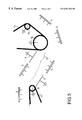
- FIG. 1 shows diagrammatically a web guidance system according to the invention adapted at the crossover point between two rolls;
- FIG. 2 shows diagrammatically a direct web guidance arrangement between two rolls
- FIG. 3 shows an edge strip guidance arrangement according to the invention between two rope loops
- FIG. 4 shows a guidance arrangement according to the invention for engaging the web tail around a winder mandrel
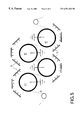
- FIG. 5 shows a draw roll group in which the web is adhered to the rolls by electrical means.
- electric forces can be used for adhering a web or an edge strip thereof to a moving carrier such as a wire, belt, band or for guiding around a roll.
- a moving carrier such as a wire, belt, band or for guiding around a roll.
- Web guidance may, however, be implemented more advantageously using the so-called ion-blast technique particularly in cases where the web is desired to be guided by means of the method according to the invention along a curved path.
- the ion-blast technique is based on forming a strong electric field between one or typically a plurality of pointed electrodes and one planar counterelectrode.
- the tip of the pointed electrode emits a corona discharge that charges particles located in the vicinity of the electrode tip thus causing the generation of ions in the electronegative gaseous medium.
- the ions migrate along the field lines extending between the electrode and the counterelectrode which is taken to the ground potential or even to a lower potential, whereby the ions adhere to particles they meet on their travel.
- the electric field transports the charged particles over the interelectrode gap toward the ground-potential electrode, where they attach to the substrate by electric and mechanical forces.
- the distance between the opposed electrodes is large and the applied voltage is high (more than 50 kV); a gas flow is established between the opposed electrodes that mechanically transports the charged particles within the interelectrode gap toward the ground potential.
- This flow is conventionally known as ion blast.
- the electric field exiting from the tip of the pointed electrode forms a conical field pattern in which the ionized gas and charged particles move.
- the effective coverage of the conical flux tubes emitted by the electrode tips must extend over the desired area on the web.
- the number and location of electrode tips must be configured so that the conical flux tubes leaving the staggered electrode tips provide a field pattern of uniform coverage on the counterelectrode.
- the voltage applied to the electrodes is dependent on the distance between the counterelectrode and the electrode tips that may be varied from 2 mm to 2 m; however, to keep the space requirements of the different devices comprised in the equipment within practicable limits, an interelectrode distance range of 100-1000 mm is favored.
- the voltage applied between the opposed electrodes is typically set to be in the range 80-160 kV, but may be varied as widely as from 30 kV to 1000 kV.
- the counterelectrode may be run positive or negative, and the electrode tips may respectively be connected to the negative or positive terminal of the power supply.
- FIG. 1 is shown the control of web travel by means of ion-blast devices along a curved path downstream from a first roll 1 to a second roll 2 .
- This arrangement is suited for, e.g., guiding the web from a coating station backing roll 1 in a noncontacting manner along a curved path to a first lead-in roll 2 of the dryer section.
- the counterelectrodes 3 that form the lower-potential electrodes 3 are disposed on the outer perimeter side of the curved web path, while the pointed electrodes 5 placed in enclosures 4 are disposed on the inner perimeter side of the curved web path.
- the ion blast emitted by the pointed electrodes 5 moves the web 6 by electric forces and the mechanical effects of the ion-blast gas flow toward the ground electrodes 3 , whereby the web 6 is tensioned on a curved path determined by the arrangement of the electrodes 3 , 5 .
- the web may also be transported along a straight path if the electrodes of the higher and lower potential are disposed in an alternating manner to opposite sides of the web.
- the electrodes are in a conventional manner fed by a high-voltage power supply 18 , as is also the case in the alternative embodiments described later in the text.
- the polarity of the electrodes is made changeable, e.g., by providing the power supply with appropriate switch-over means. Then, the polarity change can be implemented by manual means or, alternatively, utilized for automated control of web travel.
- FIG. 2 is shown the adherence of the web to a support belt 7 .
- the support belt is arranged to travel about a set of guide rolls 8 disposed in a triangular configuration in which two of the guide rolls 8 are placed in a close proximity of web guide rolls 9 so that the web 6 travels supported by said belt between said latter rolls.
- Over the travel of the web 6 supported by the belt 7 there are disposed three counterelectrodes 3 and three separate groups of ion-blast electrodes are located thereabove on the opposite side of the web.
- the web support belt is advantageously made from a conducting material. In the illustrated embodiment, the web 6 is adhered by electric forces to the belt 7 and, supported by the said belt, travels the distance between the guide rolls 9 supporting the web 6 .
- the same assembly may be used for guiding and supporting an edge strip or a full-width web between two support elements such as a belt or wire or for supporting an edge strip over the distance between two rope nips.
- the assembly is advantageously made movable, thus allowing the assembly to be introduced to the crossover point of the support system at the start of tail threading and then to be retracted after a successful web threading operation.
- FIG. 3 is shown an arrangement according to the invention for guiding the edge strip at the crossover point between two support belts. Also an arrangement may be contemplated capable of guiding a full-width web at the cross-over point of two support belts or wires.
- the edge strip 10 leaves a first guide belt 11 to be next passed via the gap formed between electrodes 5 and 3 of a deflection roll onto another guide belt 13 arranged to pass over rolls 14 , 15 . From the first belt 10 , the edge strip is guided by means of the electrodes 3 , 5 to a roll 14 from which the edge strip 10 is deflected by means of a second set of electrodes 5 toward the guide belt 13 passing over the guide roll 14 .
- the edge strip 10 is transported by being adhered to the guide belts 11 and 13 with the help of electrical field techniques.
- the first guide belt 11 passes over at least one guide roll 12 taken to a lower potential, thereby also taking the guide belt 11 to said lower potential.
- a higher-potential electrode 5 that in cooperation with the conducting guide belt 11 forms an electric field capable of adhering the edge strip to the guide belt 11 .
- the edge strip 10 is adhered in a similar manner with the help of the field emitted by the guide electrodes 5 to the next guide belt which is taken to the ground potential via guide rolls 14 , 15 .
- the edge strip 10 is transported with the help of the electric field formed between the fixed electrodes 3 , 5 .
- These electrodes are arranged so that to opposite sides of the travelling edge strip are disposed electrodes taken in an alternating order to a lower and a higher potential, thus causing the direction of the electric field to change cyclically so that the edge strip stays centered between the electrodes. In this fashion, the edge strip can be passed through the entire machine adheringly supported by the guide belts.
- FIG. 4 is shown one technique of guiding the web tail around a winder mandrel 17 .
- the mandrel 17 is brought to the lower potential, advantageously to the ground potential, and the electrodes taken to the higher potential are arranged in groups surrounding the mandrel 16 . Since this arrangement functions very satisfactorily based on the electrostatic field alone, the shape of the electrodes can be varied freely. As ion-blast forces, however, offer a more effective technique of moving the tail of the web 6 toward the mandrel 16 , the use of pointed electrodes combined with a high potential difference is more advantageous.
- the assembly of FIG. 4 can be used for guiding a web tail to rolls or cylinders, it requires additional means such as a mechanical scraper for preventing the winding-up of the web tail about the roll/cylinder and for urging the tail to travel forward in the machine.
- FIG. 5 is shown an assembly capable of improving the adherence traction imposed by the drawing cylinder group on the web.
- the air travelling as a boundary layer on the web surface becomes entrained into the converging nip between the rolls 17 and the web 16 , whereby the traction of the nip on the web is lost.
- the traction can be improved by taking the draw rolls 17 to a low potential, advantageously to the ground potential, and simultaneously arranging to a close proximity thereof a set of higher-potential electrodes 5 , whereby the electric field established between the rolls and the electrodes adheres the web to the draw rolls without any loss of traction.
- the electric field also increases the mechanical friction by preventing the entry of air into the nip between the rolls and the web.
- the arrangement of FIG. 5 may also be used in conjunction with other rolls such as dryer cylinders not equipped with a support wire.
- the invention may be utilized for preventing bagginess of the web. Bagginess results from the entrapment of air travelling along with the web into the converging nip between a roll and the web passing over the same, thus separating the web from the roll, whereby a bag is formed in the web in front of a coating applicator or the doctor units when the web is pressed against the backing roll. Bagginess can be avoided by taking the backing roll to the ground potential or a low potential and disposing at the tangential meeting point of the web with the backing roll an electrode which is taken to a higher potential, whereby the web adheres under the electric forces to the roll and, simultaneously, the entry of air into the nip between the roll and the web is prevented.
- the ion-blast apparatus may under some conditions act as a capacitor that accumulates an electric charge, whereby the forces adhering the web to the conducting support element become unwieldy after the web has exited from under the counterelectrode.
- a positive- or negative-potential corona discharge treatment can be applied downstream from the electrodes.
- the required corona treatment is applied using a device similar to the above-described ion-blast assembly.
- the electrodes may be shaped as planar or rail electrodes, and respectively, the counter-electrode need not necessarily be taken to the ground potential with the provision that its potential must obviously be lower than that of the corona-discharge-emitting electrodes or other high-potential electrodes.
Abstract
Description
Claims (20)
Applications Claiming Priority (3)
| Application Number | Priority Date | Filing Date | Title |
|---|---|---|---|
| FI981786A FI104645B (en) | 1998-08-19 | 1998-08-19 | Method and arrangement for controlling paper or cardboard during manufacture |
| FI981786 | 1998-08-19 | ||
| PCT/FI1999/000686 WO2000011266A1 (en) | 1998-08-19 | 1999-08-19 | Method and assembly for guiding a web of paper or board web during manufacture |
Publications (1)
| Publication Number | Publication Date |
|---|---|
| US6551562B1 true US6551562B1 (en) | 2003-04-22 |
Family
ID=8552332
Family Applications (1)
| Application Number | Title | Priority Date | Filing Date |
|---|---|---|---|
| US09/762,825 Expired - Fee Related US6551562B1 (en) | 1998-08-19 | 1999-08-19 | Method and apparatus for guiding a web of paper or board web during manufacture |
Country Status (11)
| Country | Link |
|---|---|
| US (1) | US6551562B1 (en) |
| EP (1) | EP1121486B1 (en) |
| JP (1) | JP2002523643A (en) |
| KR (1) | KR20010072790A (en) |
| AT (1) | ATE271155T1 (en) |
| AU (1) | AU754392B2 (en) |
| BR (1) | BR9913085A (en) |
| CA (1) | CA2341025A1 (en) |
| DE (1) | DE69918706T2 (en) |
| FI (1) | FI104645B (en) |
| WO (1) | WO2000011266A1 (en) |
Cited By (3)
| Publication number | Priority date | Publication date | Assignee | Title |
|---|---|---|---|---|
| US20020069990A1 (en) * | 2000-12-08 | 2002-06-13 | Voith Paper Patent Gmbh & Co. Kg | Machine to manufacture a fibrous material web |
| FR2894600A1 (en) * | 2005-12-13 | 2007-06-15 | Asselin Thibeau Soc Par Action | Non-woven material strip conveyor uses electrostatic charge to hold strip on conveyor belt where it slopes or varies in speed |
| US20080196854A1 (en) * | 2005-06-16 | 2008-08-21 | Helmut Figalist | Sieve Mechanism For the Production of Paper, and Method For the Treatment of Non-Woven Fibers |
Families Citing this family (2)
| Publication number | Priority date | Publication date | Assignee | Title |
|---|---|---|---|---|
| WO2004035922A1 (en) * | 2002-10-17 | 2004-04-29 | Metso Paper, Inc. | Method and apparatus for the transverse control of a track |
| FR3017314B1 (en) * | 2014-02-10 | 2016-03-04 | Systemes Et Technologies De Traitement De Surface | METHOD AND INSTALLATION FOR PROCESSING WORKPIECES TO INCREASE ADHESION. |
Citations (3)
| Publication number | Priority date | Publication date | Assignee | Title |
|---|---|---|---|---|
| USRE26951E (en) * | 1956-12-31 | 1970-09-22 | Method and apparatus for feeding and coating a web | |
| US4257167A (en) | 1978-09-22 | 1981-03-24 | Siemens Aktiengesellschaft | Arrangement for supporting a web, especially a paper web |
| US4852820A (en) * | 1986-12-04 | 1989-08-01 | Gottlieb Looser | Winding method and apparatus |
-
1998
- 1998-08-19 FI FI981786A patent/FI104645B/en not_active IP Right Cessation
-
1999
- 1999-08-19 BR BR9913085-8A patent/BR9913085A/en not_active Application Discontinuation
- 1999-08-19 CA CA002341025A patent/CA2341025A1/en not_active Abandoned
- 1999-08-19 AT AT99939467T patent/ATE271155T1/en not_active IP Right Cessation
- 1999-08-19 JP JP2000566507A patent/JP2002523643A/en not_active Abandoned
- 1999-08-19 KR KR1020017002139A patent/KR20010072790A/en not_active Application Discontinuation
- 1999-08-19 EP EP99939467A patent/EP1121486B1/en not_active Expired - Lifetime
- 1999-08-19 DE DE69918706T patent/DE69918706T2/en not_active Expired - Fee Related
- 1999-08-19 WO PCT/FI1999/000686 patent/WO2000011266A1/en not_active Application Discontinuation
- 1999-08-19 US US09/762,825 patent/US6551562B1/en not_active Expired - Fee Related
- 1999-08-19 AU AU53751/99A patent/AU754392B2/en not_active Ceased
Patent Citations (3)
| Publication number | Priority date | Publication date | Assignee | Title |
|---|---|---|---|---|
| USRE26951E (en) * | 1956-12-31 | 1970-09-22 | Method and apparatus for feeding and coating a web | |
| US4257167A (en) | 1978-09-22 | 1981-03-24 | Siemens Aktiengesellschaft | Arrangement for supporting a web, especially a paper web |
| US4852820A (en) * | 1986-12-04 | 1989-08-01 | Gottlieb Looser | Winding method and apparatus |
Cited By (4)
| Publication number | Priority date | Publication date | Assignee | Title |
|---|---|---|---|---|
| US20020069990A1 (en) * | 2000-12-08 | 2002-06-13 | Voith Paper Patent Gmbh & Co. Kg | Machine to manufacture a fibrous material web |
| US20080196854A1 (en) * | 2005-06-16 | 2008-08-21 | Helmut Figalist | Sieve Mechanism For the Production of Paper, and Method For the Treatment of Non-Woven Fibers |
| FR2894600A1 (en) * | 2005-12-13 | 2007-06-15 | Asselin Thibeau Soc Par Action | Non-woven material strip conveyor uses electrostatic charge to hold strip on conveyor belt where it slopes or varies in speed |
| EP1798175A1 (en) * | 2005-12-13 | 2007-06-20 | Asselin-Thibeau | Transport of a non-woven band by means of a conveyor belt with an ascending portion and/or variable speed |
Also Published As
| Publication number | Publication date |
|---|---|
| AU5375199A (en) | 2000-03-14 |
| CA2341025A1 (en) | 2000-03-02 |
| FI981786A0 (en) | 1998-08-19 |
| EP1121486B1 (en) | 2004-07-14 |
| DE69918706D1 (en) | 2004-08-19 |
| FI104645B (en) | 2000-03-15 |
| AU754392B2 (en) | 2002-11-14 |
| ATE271155T1 (en) | 2004-07-15 |
| KR20010072790A (en) | 2001-07-31 |
| WO2000011266A1 (en) | 2000-03-02 |
| DE69918706T2 (en) | 2004-12-02 |
| EP1121486A1 (en) | 2001-08-08 |
| BR9913085A (en) | 2001-05-08 |
| JP2002523643A (en) | 2002-07-30 |
Similar Documents
| Publication | Publication Date | Title |
|---|---|---|
| US6311921B1 (en) | Winding device and method for winding web material | |
| CA2907802C (en) | A reel-up for winding a paper web into a roll and a method of winding a paper web to form a roll | |
| US6551562B1 (en) | Method and apparatus for guiding a web of paper or board web during manufacture | |
| FI111475B (en) | Method and arrangement for controlling fog and dust in paper and board manufacturing and finishing | |
| JP2001526160A (en) | Method and apparatus in a paper machine, a coater, an intermediate winder, a rewind stand of a slitter winder or in any other equipment for processing webs | |
| PL157653B1 (en) | Yarns supplying device and the method of yarns supply from pressing section to drying section | |
| EP0731860B1 (en) | Assembly for a paper web coating line | |
| US6533899B1 (en) | Device for conveying and guiding a lead-in strip of a web in a paper machine | |
| FI59833B (en) | SPETSDRAGNINGSANORDNING FOER EN PAPPERSBANA | |
| US20020069990A1 (en) | Machine to manufacture a fibrous material web | |
| US6235156B1 (en) | Method for paper web transfer and transfer apparatus for paper web | |
| EP1062389B1 (en) | Method and arrangement for coating a moving web of paper or board | |
| US1104759A (en) | Drier-rolls for paper-machines. | |
| EP0611716B1 (en) | Assembly for the unwinder end of an off-machine paper web handling line | |
| SE9403562L (en) | Method and apparatus for assuring the running of the web in a multi-cylinder dryer device of a paper machine | |
| WO2004035922A1 (en) | Method and apparatus for the transverse control of a track | |
| FI117170B (en) | Control of a loaded path | |
| FI83894B (en) | Method and device for loosening a web | |
| JP5616013B2 (en) | How to pass through the dry part of a paper machine | |
| WO2004035443A1 (en) | Web tension control | |
| JPH02209349A (en) | Web roll device | |
| JP2004225197A (en) | Paper guide apparatus in paper machine |
Legal Events
| Date | Code | Title | Description |
|---|---|---|---|
| AS | Assignment |
Owner name: METSO PAPER, INC., FINLAND Free format text: CORRECTION TO THE ASSIGNOR'S NAME;ASSIGNORS:AHVENNIEMI, VESA;KINNUNEN, JORMA;LUOMI, SEPPO;AND OTHERS;REEL/FRAME:012150/0719 Effective date: 20010309 Owner name: VALMET CORPORATION, FINLAND Free format text: ASSIGNMENT OF ASSIGNORS INTEREST;ASSIGNORS:AHVENNIEMI, VESA;KINNUNEN, JORMA;LUOMI, SEPPO;AND OTHERS;REEL/FRAME:011875/0522 Effective date: 20010309 |
|
| FPAY | Fee payment |
Year of fee payment: 4 |
|
| REMI | Maintenance fee reminder mailed | ||
| LAPS | Lapse for failure to pay maintenance fees | ||
| STCH | Information on status: patent discontinuation |
Free format text: PATENT EXPIRED DUE TO NONPAYMENT OF MAINTENANCE FEES UNDER 37 CFR 1.362 |
|
| FP | Lapsed due to failure to pay maintenance fee |
Effective date: 20110422 |
|
| AS | Assignment |
Owner name: VALMET TECHNOLOGIES, INC., FINLAND Free format text: CHANGE OF NAME;ASSIGNOR:METSO PAPER, INC.;REEL/FRAME:032551/0426 Effective date: 20131212 |