US6549720B1 - Picture signal processing method and apparatus, picture signal recording method and apparatus and recording medium - Google Patents
Picture signal processing method and apparatus, picture signal recording method and apparatus and recording medium Download PDFInfo
- Publication number
- US6549720B1 US6549720B1 US09/281,664 US28166499A US6549720B1 US 6549720 B1 US6549720 B1 US 6549720B1 US 28166499 A US28166499 A US 28166499A US 6549720 B1 US6549720 B1 US 6549720B1
- Authority
- US
- United States
- Prior art keywords
- picture
- recording
- sequence
- bitstream
- resolution
- Prior art date
- Legal status (The legal status is an assumption and is not a legal conclusion. Google has not performed a legal analysis and makes no representation as to the accuracy of the status listed.)
- Expired - Lifetime
Links
Images


Classifications
-
- H—ELECTRICITY
- H04—ELECTRIC COMMUNICATION TECHNIQUE
- H04N—PICTORIAL COMMUNICATION, e.g. TELEVISION
- H04N9/00—Details of colour television systems
- H04N9/79—Processing of colour television signals in connection with recording
- H04N9/7921—Processing of colour television signals in connection with recording for more than one processing mode
-
- H—ELECTRICITY
- H04—ELECTRIC COMMUNICATION TECHNIQUE
- H04N—PICTORIAL COMMUNICATION, e.g. TELEVISION
- H04N5/00—Details of television systems
- H04N5/76—Television signal recording
- H04N5/91—Television signal processing therefor
- H04N5/92—Transformation of the television signal for recording, e.g. modulation, frequency changing; Inverse transformation for playback
-
- G—PHYSICS
- G11—INFORMATION STORAGE
- G11B—INFORMATION STORAGE BASED ON RELATIVE MOVEMENT BETWEEN RECORD CARRIER AND TRANSDUCER
- G11B27/00—Editing; Indexing; Addressing; Timing or synchronising; Monitoring; Measuring tape travel
- G11B27/02—Editing, e.g. varying the order of information signals recorded on, or reproduced from, record carriers
- G11B27/031—Electronic editing of digitised analogue information signals, e.g. audio or video signals
- G11B27/034—Electronic editing of digitised analogue information signals, e.g. audio or video signals on discs
-
- G—PHYSICS
- G11—INFORMATION STORAGE
- G11B—INFORMATION STORAGE BASED ON RELATIVE MOVEMENT BETWEEN RECORD CARRIER AND TRANSDUCER
- G11B27/00—Editing; Indexing; Addressing; Timing or synchronising; Monitoring; Measuring tape travel
- G11B27/10—Indexing; Addressing; Timing or synchronising; Measuring tape travel
- G11B27/102—Programmed access in sequence to addressed parts of tracks of operating record carriers
- G11B27/105—Programmed access in sequence to addressed parts of tracks of operating record carriers of operating discs
-
- G—PHYSICS
- G11—INFORMATION STORAGE
- G11B—INFORMATION STORAGE BASED ON RELATIVE MOVEMENT BETWEEN RECORD CARRIER AND TRANSDUCER
- G11B27/00—Editing; Indexing; Addressing; Timing or synchronising; Monitoring; Measuring tape travel
- G11B27/10—Indexing; Addressing; Timing or synchronising; Measuring tape travel
- G11B27/19—Indexing; Addressing; Timing or synchronising; Measuring tape travel by using information detectable on the record carrier
- G11B27/28—Indexing; Addressing; Timing or synchronising; Measuring tape travel by using information detectable on the record carrier by using information signals recorded by the same method as the main recording
- G11B27/30—Indexing; Addressing; Timing or synchronising; Measuring tape travel by using information detectable on the record carrier by using information signals recorded by the same method as the main recording on the same track as the main recording
- G11B27/3027—Indexing; Addressing; Timing or synchronising; Measuring tape travel by using information detectable on the record carrier by using information signals recorded by the same method as the main recording on the same track as the main recording used signal is digitally coded
-
- G—PHYSICS
- G11—INFORMATION STORAGE
- G11B—INFORMATION STORAGE BASED ON RELATIVE MOVEMENT BETWEEN RECORD CARRIER AND TRANSDUCER
- G11B27/00—Editing; Indexing; Addressing; Timing or synchronising; Monitoring; Measuring tape travel
- G11B27/10—Indexing; Addressing; Timing or synchronising; Measuring tape travel
- G11B27/19—Indexing; Addressing; Timing or synchronising; Measuring tape travel by using information detectable on the record carrier
- G11B27/28—Indexing; Addressing; Timing or synchronising; Measuring tape travel by using information detectable on the record carrier by using information signals recorded by the same method as the main recording
- G11B27/32—Indexing; Addressing; Timing or synchronising; Measuring tape travel by using information detectable on the record carrier by using information signals recorded by the same method as the main recording on separate auxiliary tracks of the same or an auxiliary record carrier
- G11B27/327—Table of contents
- G11B27/329—Table of contents on a disc [VTOC]
-
- H—ELECTRICITY
- H04—ELECTRIC COMMUNICATION TECHNIQUE
- H04N—PICTORIAL COMMUNICATION, e.g. TELEVISION
- H04N19/00—Methods or arrangements for coding, decoding, compressing or decompressing digital video signals
- H04N19/10—Methods or arrangements for coding, decoding, compressing or decompressing digital video signals using adaptive coding
- H04N19/134—Methods or arrangements for coding, decoding, compressing or decompressing digital video signals using adaptive coding characterised by the element, parameter or criterion affecting or controlling the adaptive coding
-
- H—ELECTRICITY
- H04—ELECTRIC COMMUNICATION TECHNIQUE
- H04N—PICTORIAL COMMUNICATION, e.g. TELEVISION
- H04N19/00—Methods or arrangements for coding, decoding, compressing or decompressing digital video signals
- H04N19/50—Methods or arrangements for coding, decoding, compressing or decompressing digital video signals using predictive coding
- H04N19/59—Methods or arrangements for coding, decoding, compressing or decompressing digital video signals using predictive coding involving spatial sub-sampling or interpolation, e.g. alteration of picture size or resolution
-
- H—ELECTRICITY
- H04—ELECTRIC COMMUNICATION TECHNIQUE
- H04N—PICTORIAL COMMUNICATION, e.g. TELEVISION
- H04N19/00—Methods or arrangements for coding, decoding, compressing or decompressing digital video signals
- H04N19/80—Details of filtering operations specially adapted for video compression, e.g. for pixel interpolation
-
- H—ELECTRICITY
- H04—ELECTRIC COMMUNICATION TECHNIQUE
- H04N—PICTORIAL COMMUNICATION, e.g. TELEVISION
- H04N21/00—Selective content distribution, e.g. interactive television or video on demand [VOD]
- H04N21/40—Client devices specifically adapted for the reception of or interaction with content, e.g. set-top-box [STB]; Operations thereof
- H04N21/43—Processing of content or additional data, e.g. demultiplexing additional data from a digital video stream; Elementary client operations, e.g. monitoring of home network or synchronising decoder's clock; Client middleware
- H04N21/432—Content retrieval operation from a local storage medium, e.g. hard-disk
- H04N21/4325—Content retrieval operation from a local storage medium, e.g. hard-disk by playing back content from the storage medium
-
- H—ELECTRICITY
- H04—ELECTRIC COMMUNICATION TECHNIQUE
- H04N—PICTORIAL COMMUNICATION, e.g. TELEVISION
- H04N21/00—Selective content distribution, e.g. interactive television or video on demand [VOD]
- H04N21/40—Client devices specifically adapted for the reception of or interaction with content, e.g. set-top-box [STB]; Operations thereof
- H04N21/43—Processing of content or additional data, e.g. demultiplexing additional data from a digital video stream; Elementary client operations, e.g. monitoring of home network or synchronising decoder's clock; Client middleware
- H04N21/433—Content storage operation, e.g. storage operation in response to a pause request, caching operations
- H04N21/4334—Recording operations
-
- H—ELECTRICITY
- H04—ELECTRIC COMMUNICATION TECHNIQUE
- H04N—PICTORIAL COMMUNICATION, e.g. TELEVISION
- H04N21/00—Selective content distribution, e.g. interactive television or video on demand [VOD]
- H04N21/40—Client devices specifically adapted for the reception of or interaction with content, e.g. set-top-box [STB]; Operations thereof
- H04N21/43—Processing of content or additional data, e.g. demultiplexing additional data from a digital video stream; Elementary client operations, e.g. monitoring of home network or synchronising decoder's clock; Client middleware
- H04N21/44—Processing of video elementary streams, e.g. splicing a video clip retrieved from local storage with an incoming video stream, rendering scenes according to MPEG-4 scene graphs
- H04N21/4402—Processing of video elementary streams, e.g. splicing a video clip retrieved from local storage with an incoming video stream, rendering scenes according to MPEG-4 scene graphs involving reformatting operations of video signals for household redistribution, storage or real-time display
- H04N21/440263—Processing of video elementary streams, e.g. splicing a video clip retrieved from local storage with an incoming video stream, rendering scenes according to MPEG-4 scene graphs involving reformatting operations of video signals for household redistribution, storage or real-time display by altering the spatial resolution, e.g. for displaying on a connected PDA
-
- H—ELECTRICITY
- H04—ELECTRIC COMMUNICATION TECHNIQUE
- H04N—PICTORIAL COMMUNICATION, e.g. TELEVISION
- H04N21/00—Selective content distribution, e.g. interactive television or video on demand [VOD]
- H04N21/40—Client devices specifically adapted for the reception of or interaction with content, e.g. set-top-box [STB]; Operations thereof
- H04N21/45—Management operations performed by the client for facilitating the reception of or the interaction with the content or administrating data related to the end-user or to the client device itself, e.g. learning user preferences for recommending movies, resolving scheduling conflicts
- H04N21/462—Content or additional data management, e.g. creating a master electronic program guide from data received from the Internet and a Head-end, controlling the complexity of a video stream by scaling the resolution or bit-rate based on the client capabilities
- H04N21/4621—Controlling the complexity of the content stream or additional data, e.g. lowering the resolution or bit-rate of the video stream for a mobile client with a small screen
-
- G—PHYSICS
- G11—INFORMATION STORAGE
- G11B—INFORMATION STORAGE BASED ON RELATIVE MOVEMENT BETWEEN RECORD CARRIER AND TRANSDUCER
- G11B2220/00—Record carriers by type
- G11B2220/20—Disc-shaped record carriers
- G11B2220/21—Disc-shaped record carriers characterised in that the disc is of read-only, rewritable, or recordable type
- G11B2220/215—Recordable discs
- G11B2220/216—Rewritable discs
-
- G—PHYSICS
- G11—INFORMATION STORAGE
- G11B—INFORMATION STORAGE BASED ON RELATIVE MOVEMENT BETWEEN RECORD CARRIER AND TRANSDUCER
- G11B2220/00—Record carriers by type
- G11B2220/20—Disc-shaped record carriers
- G11B2220/25—Disc-shaped record carriers characterised in that the disc is based on a specific recording technology
- G11B2220/2525—Magneto-optical [MO] discs
- G11B2220/2529—Mini-discs
-
- G—PHYSICS
- G11—INFORMATION STORAGE
- G11B—INFORMATION STORAGE BASED ON RELATIVE MOVEMENT BETWEEN RECORD CARRIER AND TRANSDUCER
- G11B2220/00—Record carriers by type
- G11B2220/20—Disc-shaped record carriers
- G11B2220/25—Disc-shaped record carriers characterised in that the disc is based on a specific recording technology
- G11B2220/2537—Optical discs
- G11B2220/2545—CDs
-
- G—PHYSICS
- G11—INFORMATION STORAGE
- G11B—INFORMATION STORAGE BASED ON RELATIVE MOVEMENT BETWEEN RECORD CARRIER AND TRANSDUCER
- G11B2220/00—Record carriers by type
- G11B2220/20—Disc-shaped record carriers
- G11B2220/25—Disc-shaped record carriers characterised in that the disc is based on a specific recording technology
- G11B2220/2537—Optical discs
- G11B2220/2562—DVDs [digital versatile discs]; Digital video discs; MMCDs; HDCDs
-
- G—PHYSICS
- G11—INFORMATION STORAGE
- G11B—INFORMATION STORAGE BASED ON RELATIVE MOVEMENT BETWEEN RECORD CARRIER AND TRANSDUCER
- G11B2220/00—Record carriers by type
- G11B2220/90—Tape-like record carriers
-
- G—PHYSICS
- G11—INFORMATION STORAGE
- G11B—INFORMATION STORAGE BASED ON RELATIVE MOVEMENT BETWEEN RECORD CARRIER AND TRANSDUCER
- G11B2220/00—Record carriers by type
- G11B2220/90—Tape-like record carriers
- G11B2220/91—Helical scan format, wherein tracks are slightly tilted with respect to tape direction, e.g. VHS, DAT, DVC, AIT or exabyte
- G11B2220/913—Digital audio tape [DAT] format
-
- G—PHYSICS
- G11—INFORMATION STORAGE
- G11B—INFORMATION STORAGE BASED ON RELATIVE MOVEMENT BETWEEN RECORD CARRIER AND TRANSDUCER
- G11B27/00—Editing; Indexing; Addressing; Timing or synchronising; Monitoring; Measuring tape travel
- G11B27/10—Indexing; Addressing; Timing or synchronising; Measuring tape travel
- G11B27/102—Programmed access in sequence to addressed parts of tracks of operating record carriers
- G11B27/107—Programmed access in sequence to addressed parts of tracks of operating record carriers of operating tapes
-
- G—PHYSICS
- G11—INFORMATION STORAGE
- G11B—INFORMATION STORAGE BASED ON RELATIVE MOVEMENT BETWEEN RECORD CARRIER AND TRANSDUCER
- G11B27/00—Editing; Indexing; Addressing; Timing or synchronising; Monitoring; Measuring tape travel
- G11B27/10—Indexing; Addressing; Timing or synchronising; Measuring tape travel
- G11B27/19—Indexing; Addressing; Timing or synchronising; Measuring tape travel by using information detectable on the record carrier
- G11B27/28—Indexing; Addressing; Timing or synchronising; Measuring tape travel by using information detectable on the record carrier by using information signals recorded by the same method as the main recording
- G11B27/32—Indexing; Addressing; Timing or synchronising; Measuring tape travel by using information detectable on the record carrier by using information signals recorded by the same method as the main recording on separate auxiliary tracks of the same or an auxiliary record carrier
- G11B27/327—Table of contents
- G11B27/328—Table of contents on a tape [TTOC]
-
- H—ELECTRICITY
- H04—ELECTRIC COMMUNICATION TECHNIQUE
- H04N—PICTORIAL COMMUNICATION, e.g. TELEVISION
- H04N21/00—Selective content distribution, e.g. interactive television or video on demand [VOD]
- H04N21/40—Client devices specifically adapted for the reception of or interaction with content, e.g. set-top-box [STB]; Operations thereof
- H04N21/41—Structure of client; Structure of client peripherals
- H04N21/426—Internal components of the client ; Characteristics thereof
- H04N21/42646—Internal components of the client ; Characteristics thereof for reading from or writing on a non-volatile solid state storage medium, e.g. DVD, CD-ROM
-
- H—ELECTRICITY
- H04—ELECTRIC COMMUNICATION TECHNIQUE
- H04N—PICTORIAL COMMUNICATION, e.g. TELEVISION
- H04N5/00—Details of television systems
- H04N5/76—Television signal recording
- H04N5/84—Television signal recording using optical recording
- H04N5/85—Television signal recording using optical recording on discs or drums
-
- H—ELECTRICITY
- H04—ELECTRIC COMMUNICATION TECHNIQUE
- H04N—PICTORIAL COMMUNICATION, e.g. TELEVISION
- H04N9/00—Details of colour television systems
- H04N9/79—Processing of colour television signals in connection with recording
- H04N9/80—Transformation of the television signal for recording, e.g. modulation, frequency changing; Inverse transformation for playback
- H04N9/804—Transformation of the television signal for recording, e.g. modulation, frequency changing; Inverse transformation for playback involving pulse code modulation of the colour picture signal components
- H04N9/8042—Transformation of the television signal for recording, e.g. modulation, frequency changing; Inverse transformation for playback involving pulse code modulation of the colour picture signal components involving data reduction
-
- H—ELECTRICITY
- H04—ELECTRIC COMMUNICATION TECHNIQUE
- H04N—PICTORIAL COMMUNICATION, e.g. TELEVISION
- H04N9/00—Details of colour television systems
- H04N9/79—Processing of colour television signals in connection with recording
- H04N9/80—Transformation of the television signal for recording, e.g. modulation, frequency changing; Inverse transformation for playback
- H04N9/82—Transformation of the television signal for recording, e.g. modulation, frequency changing; Inverse transformation for playback the individual colour picture signal components being recorded simultaneously only
- H04N9/8205—Transformation of the television signal for recording, e.g. modulation, frequency changing; Inverse transformation for playback the individual colour picture signal components being recorded simultaneously only involving the multiplexing of an additional signal and the colour video signal
Definitions
- This invention relates to a picture signal processing method and apparatus, a picture signal recording method and apparatus, and a recording medium, relevant to the expression of a bitstream syntax of the MPEG (Moving Pictures Experts Group) 2 standard which provides seamless reproduction of resolution switching.
- MPEG Motion Picture Experts Group
- the MPEG (Moving Pictures Experts Group) 2 is an encoding system used in broadcast or AV equipments, and which has become extremely popular as an information compression technique for pictures/ speech/ data.
- each picture is divided in m ⁇ n blocks and transformed by orthogonal transform to concentrate the signal power in order to compress the total information volume.
- picture data of the MPEG 2 is made up of a sequence layer of a picture group having a series of the same attributes, a GOP (group-of-picture) layer, representing the minimum unit of a picture group as a random-accessing unit, a picture layer of a common attribute to a sole picture, a slice layer of the common information to a small picture obtained on optionally splitting a sole picture, a macro-block layer of the information common to pixel blocks (macro-blocks) obtained on further splitting the slice layer, and a block layer of transform coefficients per se.
- GOP group-of-picture
- the picture layer has, as its object, a picture of 704(H) ⁇ 480(V), in e.g., television signals of the NTSC system, in accordance with the main level format.
- the respective pictures are classified into an intra-picture (I-picture), as an intra-coded picture, a forward predictive-coded picture or a P-picture, predictively coded in the forward direction in the display sequence, and a bidirectionally predictivecoded picture or a B-picture, predictive-coded in both the forward and backward directions in the display sequence.
- I-picture intra-picture
- P-picture forward predictive-coded picture or a P-picture
- B-picture predictive-coded in both the forward and backward directions in the display sequence.
- the processing of movies in the MPEG 2, such as resolution switching, is usually carried out in a video sequence unit, which is the minimum unit enabling the definition of resolution.
- a sequence as a picture source means no other than the video sequence which is a unit defining the resolution.
- the encoding size that is the resolution, cannot be switched by a control operation in the course of the sequence.
- the present invention adopts the concept of a movie sequence and prescribes the movie sequence as being a set of video sequences. To this end, the beginning and the end of the movie sequence are clarified.
- the resolution switching is adapted to be made freely in the movie sequence to improve the compression ratio.
- the same encoding size is used from the beginning to the end of the routine MPEG 2 encoding. According to the present invention, the encoding size is switched appropriately to improve the compression ratio.
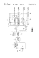
- FIG. 1 is a schematic block diagram showing a structure of a recording/reproducing apparatus according to a first embodiment of the present invention.
- FIG. 2 illustrates a sequence of movies.
- FIG. 3 shows a video sequence
- FIG. 4 shows a data structure illustrating the structure of user data.
- FIG. 5 illustrates the recording of a sequence of movies to a disc medium in a first embodiment.
- FIG. 6 is a schematic block diagram showing the structure of a recording/reproducing apparatus in a second embodiment.
- FIG. 7 illustrates the recording of a sequence of movies to a disc medium in a second embodiment.
- FIG. 8 is a flowchart for illustrating a sequence of process steps of the recording/reproducing method.
- This recording/reproducing apparatus records the identification information in an information area proper to a bitstream of the MPEG 2 standard.
- the recording/reproducing apparatus includes a pre-filtering unit 19 for processing input video signals with pre-set filtering, an MPEG 2 encoder 20 for converting signals from the pre-filtering unit 19 into a MPEG 2 bitstream, and an adaptive transform acoustic encoder 18 for processing the input audio signals with speech adaptive transform encoding, such as so-called ATRAC (adaptive transform acoustic coding).
- the recording/reproducing apparatus also includes a MUX (multiplexer) 16 for multiplexing the bitstream encoded by the MPEG 2 encoder 20 and the encoder 18 .
- the video signals are modified in filtering characteristics in the pre-filtering unit 19 , depending on the resolution, in order to process the video signals with filtering.
- the signals from the pre-filtering unit 19 are encoded by the MPEG 2 encoder 18 .
- the signals are bit-compressed by the adaptive transform acoustic encoder 18 .
- the video signals, encoded by the MPEG 2 encoder 20 , and the audio signals, encoded by the adaptive transform acoustic encoder 18 , are multiplexed by the MUX 16 .
- the recording/reproducing apparatus includes an ECC encoding/decoding unit 15 , for encoding/decoding the ECC (error correction code), a memory 14 for storing data under control by the ECC encoding/decoding unit 15 , and a data modulation/demodulation unit 13 for modulating/demodulating data.
- the recording/reproducing apparatus also includes a magnetic field modulating driver 11 for applying a modulated magnetic field across an optical disc 101 and an optical pickup 12 for illuminating/receiving the laser light for the optical disc 101 .
- the so-called ECC for error correction and synchronization patterns are appended to the data.
- the data modulation/demodulation unit 13 sequentially reads out data stored in the memory 14 and modulates the read-out data in a pre-set fashion to route the modulated data to the magnetic field modulating driver 11 .
- the magnetic field modulating driver 11 is responsive to furnished data to drive the coil for the magnetic field to apply the magnetic field across the magnetic region of the optical disc 101 .
- the optical pickup 12 illuminates a recording laser light beam or a reproducing laser light beam on the optical disc 101 , while photoelectrically converting the reproducing laser light beam reflected from the optical disc 101 into electrical signals which are outputted as playback RF signals.
- the data modulation/demodulation unit 13 demodulates the playback RF signals in a pre-set fashion and stores the demodulated data in the memory 14 .
- the ECC encoding/decoding unit 15 corrects the data for errors.
- the recording/reproducing apparatus also includes a DMUX (demultiplexer) 21 , an adaptive transform acoustic decoding unit 22 for decoding the audio data from the DMUX 21 by so-called adaptive acoustic transform, a MPEG 2 decoder 23 for decoding video data from the DMUX 21 in accordance with the MPEG 2 and a post-filtering unit 24 for filtering the signals from the MPEG 2 decoder 23 in a pre-set fashion.
- a DMUX (demultiplexer) 21 an adaptive transform acoustic decoding unit 22 for decoding the audio data from the DMUX 21 by so-called adaptive acoustic transform
- a MPEG 2 decoder 23 for decoding video data from the DMUX 21 in accordance with the MPEG 2
- a post-filtering unit 24 for filtering the signals from the MPEG 2 decoder 23 in a pre-set fashion.
- Output data of the ECC encoding/decoding unit 15 are separated by the DMUX 20 into video data and audio data.
- the audio data are processed by the adaptive transform acoustic decoding unit 22 and subsequently outputted, while the video data are processed by the MPEG 2 decoder 23 and the post-filtering unit 24 and subsequently outputted.
- the recording/reproducing apparatus includes a controller 17 for controlling the respective parts of the present movie compression/expansion device.
- This controller 17 is constituted as a so-called micro-computer, made up of, for example, a CPU, a ROM and a RAM.
- the controller 17 detects the amount of motion of the MPEG 2 encoder 20 , determines the resolution in meeting with the amount of motion to prepare resolution data, appends the resolution data to the user data and outputs the resulting data to the MPEG 2 encoder 20 .
- the controller 17 is also responsive to the resolution to control the pre-filtering unit 19 .
- the controller 17 performs control so that the resolution of a movie proximate to a still picture is kept at 704 ⁇ 480 while that for a movie exhibiting vivid motion is set to 352 ⁇ 480 and that for a movie exhibiting only limited motion is set to an intermediate value of 528 ⁇ 480.
- the controller 17 retrieved user data from the MPEG 2 decoder 23 to control the post-filtering unit 24 responsive to the resolution.
- the video sequence of the MPEG 2 standard bitstream begins with a sequence header and ends with a sequence end.
- the encoding size in this video sequence that is the resolution, is the uniquely determined recording unit.
- the video sequence representing a movie, at a start end (start_end), as shown in FIG.4, and the resolution is defined with the video sequence as a unit.
- a sole picture source (picture program) is no other than the video sequence defined by the MPEG 2, such that the resolution cannot be switched partway.
- the moving picture sequence is defined as a set of video sequences the resolution of which is determined uniquely.
- a resolution of 704 ⁇ 480 pixels is used for a movie close to a still picture
- a resolution of 704 ⁇ 480 pixels is used for the video sequence 1 and the video sequence 3 , which are movies close to a still picture
- a resolution of 352 ⁇ 480 pixels which is one-half the resolution of 704 ⁇ 480 pixels, is used for the video sequence 2 which is a movie with vigorous motion.
- the movie sequence is construed to be the beginning of each video sequence, the beginning and the end of the movie sequence defined as the set of the video sequences cannot be discriminated from each other.
- user data (user_data) of the sequence header (sequence_header) in the video sequence are utilized for specifying the beginning and the end of the movie sequence as shown in FIG. 3 and for specifying the resolution.
- the movie sequence is recorded at consecutive positions by a disc by a recording/reproducing apparatus.
- IDs which discriminate the first video sequence and the last video sequence of the movie sequence are defined. These IDs are set at the time of encoding.
- the beginning and the end points ofthe movie sequence on the disc are clarified by the IDs discriminating the first video sequence and the last video sequence making up the movie sequence.
- the 7th bit b 7 is a start ID
- the sixth bit b 6 is the end ID
- the fifth and fourth bit b 5 , b 4 are the display size conversion ratio.
- ‘b’ signifies that the binary notation system is used.
- start ID is ‘1’, it is defined as meaning the first video sequence of the movie sequence. If the end ID is ‘1’, it is defined as the last video sequence of the movie sequence.
- the conversion ratio in the horizontal and vertical directions are defined. For example, if the display conversion ratio is ‘00’(1:1), the resolution of 704 ⁇ 480 is kept.
- the display conversion ratio of ‘01’(3:4) means multiplication by 3 ⁇ 4 at the time of encoding so that the size is 528 ⁇ 480.
- the display conversion ratio of ‘10’(1:2) means multiplication by 1 ⁇ 2 at the time of encoding so that the size is 352 ⁇ 480.
- the resolution is restored by back conversion to the original resolution of 704 ⁇ 480.
- This provision is inherently meant for distinguishing from the case of encoding at the resolution of 352 ⁇ 480 by taking no measures.
- these provisions are used as the format, it is judged which sequence the video sequence has with respect to the movie sequence.
- these provisions are used as a material for judgment at the time of decoding. That is, it can be known from the above user data from which portion to which portion the movie sequence is to be decoded with which resolution.
- the recording in a disc medium as a disc-shaped recording medium of the movie sequence is explained by a schematic view of FIG. 5 .
- the disc medium 101 there is shown the state in which the video sequences VS 1 , VS 2 and VS 3 are written on the video sequence basis.
- the start ID and the end ID are ‘1’ and ‘0’, respectively.
- the start ID and the end ID are both ‘0’, whereas, in the user data of the last video sequence, the start ID is ‘0’ and the end ‘ID’ is ‘1’.
- the video sequence VS 1 is the first video sequence in the movie sequence and that the video sequence VS 3 is the last video sequence in the movie sequence.
- a recording/reproducing apparatus for recording/reproducing picture data for an optical disc is explained.
- the recording/reproducing apparatus of the second embodiment records the identification information on a management file.
- a moving picture compression expansion apparatus includes a pre-filtering unit 19 for performing pre-set filtering on input video signals, an MPEG 2 encoder 20 for converting signals from the pre-filtering unit 19 into a MPEG 2 bitstream, a so-called adaptive transfonn acoustic encoder 18 for performing adaptive acoustic encoding on the input audio signals and a MUX (multiplexer) 16 for multiplexing the bitstream encoded by the MPEG 2 encoder 20 and the adaptive transform acoustic encoder 18 .
- a pre-filtering unit 19 for performing pre-set filtering on input video signals
- an MPEG 2 encoder 20 for converting signals from the pre-filtering unit 19 into a MPEG 2 bitstream
- a so-called adaptive transfonn acoustic encoder 18 for performing adaptive acoustic encoding on the input audio signals
- MUX (multiplexer) 16 for multiplexing the bitstream encoded by the MPEG 2 encoder 20 and the adaptive transform acou
- the moving picture compression expansion apparatus also includes an ECC encoding/decoding unit 15 for encoding or decoding the so-called ECC (error correction code), a memory 14 for storing data under control by the ECC encoding/decoding unit 15 , a data modulation/demodulation unit 13 for modulating or demodulating data, a magnetic field modulating driver 11 for applying a modulated magnetic field across the optical disc 101 and an optical pickup 12 for illuninating/receiving the laser light for the optical disc 101 .
- ECC error correction code
- a memory 14 for storing data under control by the ECC encoding/decoding unit 15
- a data modulation/demodulation unit 13 for modulating or demodulating data
- a magnetic field modulating driver 11 for applying a modulated magnetic field across the optical disc 101
- an optical pickup 12 for illuninating/receiving the laser light for the optical disc 101 .
- the moving picture compression expansion apparatus also includes a DMUX (demultiplexer) 20 , an adaptive transform acoustic decoding unit 22 for audio data from the DMUX 20 , a MPEG 2 decoder 23 for decoding the video data in accordance with the MPEG 2 and a post-filtering unit 24 for performing pre-set filtering on the signals from the MPEG 2 decoder 23 .
- DMUX demultiplexer
- MPEG 2 decoder 23 for decoding the video data in accordance with the MPEG 2
- post-filtering unit 24 for performing pre-set filtering on the signals from the MPEG 2 decoder 23 .
- the moving picture compression expansion apparatus further includes a controller 17 for controlling various parts of the moving picture compression expansion apparatus.
- This controller is constituted as a so-called micro-computer made up of, for example, a CPU, a ROM and a RAM.
- the controller 17 multiplexes a management file, indicating the position of the above-described video sequence, at the time of multiplexing by the MUX 16 , to write the multiplexed management file.
- the controller 17 reads out the management file and switches the post-filtering unit 24 depending on the resolution on the video sequence basis.
- the operation of the other circuit portions is the same as that of the above described first embodiment and hence is not explained specifically.
- a movie sequence is to be recorded on a disc medium
- a hysteresis file or a management file showing the manner in which recording has been made on the disc medium, is necessarily prepared and the recording manner is prescribed by the management file.
- all addresses are recorded from the outset on the disc medium.
- the movie sequence is sequentially recorded in the vacant region on the disc medium.
- the totality of positions on the disc medium are specified by addresses.
- the first-recorded video sequence VS 1 is recorded at a nth address on the disc medium 101
- the next-recorded video sequence VS 2 is recorded at a mth address and so forth until the last-recorded video sequence VS 4 is recorded at the pth address.
- an actual management file there is written in a disc area a file stating that the first-recorded video sequence VS 1 is at the nth address, the second-recorded video sequence VS 2 is at the mth address, and so forth.
- the addresses on the disc in which have been recorded the video sequences in the movie sequence are recorded as a management file in a region separate from the region for the data of the movie sequence.
- this management file is checked, it can readily be seen in which addresses have been recorded the video sequences in the movie sequence. That is, by utilizing this file, it is possible to identify the beginning and the end of each video sequence in the movie sequence.
- This second embodiment is applied when the management file is used for combining video sequences of different resolutions to a movie sequence.
- a sequence header is appended to a video sequence and, at the next step S 12 , the amount of motion is detected from the MPEG 2 encoder.
- step S 13 it is verified, based on the amount of motion detected by the MPEG 2 encoder at step S 12 , whether or not the number of pixels is to be increased. If the number of pixels is to be increased, the ‘YES’ path is followed to step 6 and, if otherwise, the ‘NO’ path is followed to step S 14 .
- the resolution is determined. That is, at step S 14 , the resolution is set to 352 ⁇ 480 and processing transfers to step S 15 . At step S 16 , the resolution is set to 704 ⁇ 480 and processing transfers to step S 17 .
- step S 15 it is checked whether or not the resolution as set at step S 14 is the same as the current resolution. If the resolution as set at step S 14 is the same as the current resolution, the ‘YES’ path is followed to step S 12 and, if otherwise, the ‘NO’ path is followed to step S 18 .
- step S 17 it is checked whether or not the resolution as set at step S 16 is the same as the current resolution. If the resolution as set at step S 16 is the same as the current resolution, the ‘YES’ path is followed to step S 12 and, if otherwise, the ‘NO’ path is followed to step S 18 .
- step S 18 a sequence end is appended to the video sequence and processing transfers to step S 19 .
- step S 19 user data is formulated and written in a pre-set region. After the end of this step S 19 , processing reverts to step S 11 .
- This recording medium has recorded thereon picture signals encoded in accordance with the MPEG 2 standard.
- the minimum unit which permits resolution switching is a video sequence.
- the identification information concerning the relation of resolution of plural video sequences is recorded in user data which is the information proper to the bitstream.
- This sort of the recording medium is furnished as, for example, a so-called CD.
- the present invention envisages to improve the compression ratio by performing encoding processing with different encoding sizes in a sole movie sequence.
- the present invention collects plural video sequences, defined by the MPEG 2, to complete a sole movie sequence, and adapts the movie sequence to the recording/reproduction of disc mediums, such as so-called DVDs or MD.
- the disc medium has been illustrated as a recording medium in the above-described embodiments, the present invention may also be limited to a tape-shaped recording medium, such as a so-called DAT, without being limited to disc mediums.
Abstract
A picture signal processing method and apparatus, a picture signal recording method and apparatus, and a recording medium, in which resolution switching is effected seamlessly. To this end, a controller 19 has the function of reading out the identification information specifying the resolution of the bitstream and the relation between the recording units, from a user data region provided in a video stream as a minimum unit which permits switching of the resolution in a MPEG 2 standard bitstream, and of switching the resolution of the picture signals associated with the recording units.
Description
1. Field of the Invention
This invention relates to a picture signal processing method and apparatus, a picture signal recording method and apparatus, and a recording medium, relevant to the expression of a bitstream syntax of the MPEG (Moving Pictures Experts Group) 2 standard which provides seamless reproduction of resolution switching.
2. Description of the Related Art
The MPEG (Moving Pictures Experts Group) 2 is an encoding system used in broadcast or AV equipments, and which has become extremely popular as an information compression technique for pictures/ speech/ data.
In the MPEG 2, input pictures/ speech/ data etc are encoded depending on the bit rate. As for the pictures, each picture is divided in m×n blocks and transformed by orthogonal transform to concentrate the signal power in order to compress the total information volume.
The picture data, encoded by the MPEG 2, assume a hierarchical structure from a sequence layer to a block layer.
That is, picture data of the MPEG 2 is made up of a sequence layer of a picture group having a series of the same attributes, a GOP (group-of-picture) layer, representing the minimum unit of a picture group as a random-accessing unit, a picture layer of a common attribute to a sole picture, a slice layer of the common information to a small picture obtained on optionally splitting a sole picture, a macro-block layer of the information common to pixel blocks (macro-blocks) obtained on further splitting the slice layer, and a block layer of transform coefficients per se.
Of these, the picture layer has, as its object, a picture of 704(H)×480(V), in e.g., television signals of the NTSC system, in accordance with the main level format.
The respective pictures are classified into an intra-picture (I-picture), as an intra-coded picture, a forward predictive-coded picture or a P-picture, predictively coded in the forward direction in the display sequence, and a bidirectionally predictivecoded picture or a B-picture, predictive-coded in both the forward and backward directions in the display sequence. These different pictures collectively make up a group-of-pictures (GOP) layer.
Meanwhile, the processing of movies in the MPEG 2, such as resolution switching, is usually carried out in a video sequence unit, which is the minimum unit enabling the definition of resolution.
However, a sequence as a picture source means no other than the video sequence which is a unit defining the resolution. Thus, the encoding size, that is the resolution, cannot be switched by a control operation in the course of the sequence.
The result is that the resolution cannot be switched depending on the sorts of the pictures, such as still pictures or movies undergoing vivid motions, thus worsening the compression efficiency in encoding.
It is therefore an object of the present invention to provide a picture signal processing method and apparatus, a picture signal recording method and apparatus, and a recording medium in which picture signals are switched in resolution depending on the sorts of the pictures, such as still pictures or movies undergoing vivid motions.
The present invention adopts the concept of a movie sequence and prescribes the movie sequence as being a set of video sequences. To this end, the beginning and the end of the movie sequence are clarified. The resolution switching is adapted to be made freely in the movie sequence to improve the compression ratio. Specifically, the same encoding size is used from the beginning to the end of the routine MPEG 2 encoding. According to the present invention, the encoding size is switched appropriately to improve the compression ratio.
FIG. 1 is a schematic block diagram showing a structure of a recording/reproducing apparatus according to a first embodiment of the present invention.
FIG. 2 illustrates a sequence of movies.
FIG. 3 shows a video sequence.
FIG. 4 shows a data structure illustrating the structure of user data.
FIG. 5 illustrates the recording of a sequence of movies to a disc medium in a first embodiment.
FIG. 6 is a schematic block diagram showing the structure of a recording/reproducing apparatus in a second embodiment.
FIG. 7 illustrates the recording of a sequence of movies to a disc medium in a second embodiment.
FIG. 8 is a flowchart for illustrating a sequence of process steps of the recording/reproducing method.
Referring to the drawings, preferred embodiments of the present invention will be explained in detail.
As a first embodiment, a recording/reproducing apparatus for recording/reproducing data for an optical disc is explained. This recording/reproducing apparatus records the identification information in an information area proper to a bitstream of the MPEG 2 standard.
Referring to FIG. 1, the recording/reproducing apparatus includes a pre-filtering unit 19 for processing input video signals with pre-set filtering, an MPEG 2 encoder 20 for converting signals from the pre-filtering unit 19 into a MPEG 2 bitstream, and an adaptive transform acoustic encoder 18 for processing the input audio signals with speech adaptive transform encoding, such as so-called ATRAC (adaptive transform acoustic coding). The recording/reproducing apparatus also includes a MUX (multiplexer) 16 for multiplexing the bitstream encoded by the MPEG 2 encoder 20 and the encoder 18.
As for the flow of video signals, the video signals are modified in filtering characteristics in the pre-filtering unit 19, depending on the resolution, in order to process the video signals with filtering. The signals from the pre-filtering unit 19 are encoded by the MPEG 2 encoder 18.
As for the flow of audio signals, the signals are bit-compressed by the adaptive transform acoustic encoder 18.
The video signals, encoded by the MPEG 2 encoder 20, and the audio signals, encoded by the adaptive transform acoustic encoder 18, are multiplexed by the MUX 16.
Also, the recording/reproducing apparatus includes an ECC encoding/decoding unit 15, for encoding/decoding the ECC (error correction code), a memory 14 for storing data under control by the ECC encoding/decoding unit 15, and a data modulation/demodulation unit 13 for modulating/demodulating data. The recording/reproducing apparatus also includes a magnetic field modulating driver 11 for applying a modulated magnetic field across an optical disc 101 and an optical pickup 12 for illuminating/receiving the laser light for the optical disc 101.
In the ECC encoding/decoding unit 15, the so-called ECC for error correction and synchronization patterns are appended to the data. The data modulation/demodulation unit 13 sequentially reads out data stored in the memory 14 and modulates the read-out data in a pre-set fashion to route the modulated data to the magnetic field modulating driver 11.
The magnetic field modulating driver 11 is responsive to furnished data to drive the coil for the magnetic field to apply the magnetic field across the magnetic region of the optical disc 101. The optical pickup 12 illuminates a recording laser light beam or a reproducing laser light beam on the optical disc 101, while photoelectrically converting the reproducing laser light beam reflected from the optical disc 101 into electrical signals which are outputted as playback RF signals.
The data modulation/demodulation unit 13 demodulates the playback RF signals in a pre-set fashion and stores the demodulated data in the memory 14. The ECC encoding/decoding unit 15 corrects the data for errors.
The recording/reproducing apparatus also includes a DMUX (demultiplexer) 21, an adaptive transform acoustic decoding unit 22 for decoding the audio data from the DMUX 21 by so-called adaptive acoustic transform, a MPEG 2 decoder 23 for decoding video data from the DMUX 21 in accordance with the MPEG 2 and a post-filtering unit 24 for filtering the signals from the MPEG 2 decoder 23 in a pre-set fashion.
Output data of the ECC encoding/decoding unit 15 are separated by the DMUX 20 into video data and audio data. The audio data are processed by the adaptive transform acoustic decoding unit 22 and subsequently outputted, while the video data are processed by the MPEG 2 decoder 23 and the post-filtering unit 24 and subsequently outputted.
The recording/reproducing apparatus includes a controller 17 for controlling the respective parts of the present movie compression/expansion device. This controller 17 is constituted as a so-called micro-computer, made up of, for example, a CPU, a ROM and a RAM.
The controller 17 detects the amount of motion of the MPEG 2 encoder 20, determines the resolution in meeting with the amount of motion to prepare resolution data, appends the resolution data to the user data and outputs the resulting data to the MPEG 2 encoder 20. The controller 17 is also responsive to the resolution to control the pre-filtering unit 19. For example, the controller 17 performs control so that the resolution of a movie proximate to a still picture is kept at 704×480 while that for a movie exhibiting vivid motion is set to 352×480 and that for a movie exhibiting only limited motion is set to an intermediate value of 528×480. During reproduction, the controller 17 retrieved user data from the MPEG 2 decoder 23 to control the post-filtering unit 24 responsive to the resolution.
It is provided that the video sequence of the MPEG 2 standard bitstream begins with a sequence header and ends with a sequence end. The encoding size in this video sequence, that is the resolution, is the uniquely determined recording unit.
That is, there is a unit termed the video sequence, representing a movie, at a start end (start_end), as shown in FIG.4, and the resolution is defined with the video sequence as a unit.
Usually, a sole picture source (picture program) is no other than the video sequence defined by the MPEG 2, such that the resolution cannot be switched partway.
Therefore, a number of these video sequences are collected together and newly defined as a movie sequence.
That is, the moving picture sequence is defined as a set of video sequences the resolution of which is determined uniquely.
In this movie sequence, there may exist video sequences having different encoding sizes (resolutions) such that a resolution is used in a video sequence 1 and a resolution in the horizontal direction is halved in a video sequence 2.
If the resolution of 704×480 pixels is used for a movie close to a still picture, a resolution of 704×480 pixels is used for the video sequence 1 and the video sequence 3, which are movies close to a still picture, and a resolution of 352×480 pixels, which is one-half the resolution of 704×480 pixels, is used for the video sequence 2 which is a movie with vigorous motion.
In this case, if the movie sequence is construed to be the beginning of each video sequence, the beginning and the end of the movie sequence defined as the set of the video sequences cannot be discriminated from each other.
In the first embodiment, user data (user_data) of the sequence header (sequence_header) in the video sequence are utilized for specifying the beginning and the end of the movie sequence as shown in FIG. 3 and for specifying the resolution.
That is, the movie sequence is recorded at consecutive positions by a disc by a recording/reproducing apparatus. For clarifying the beginning and the end points of the movie sequence, recorded consecutively in this manner, IDs which discriminate the first video sequence and the last video sequence of the movie sequence are defined. These IDs are set at the time of encoding.
During decoding of the movie sequence, the beginning and the end points ofthe movie sequence on the disc are clarified by the IDs discriminating the first video sequence and the last video sequence making up the movie sequence.
For the IDs specifying the positions of the video sequences in these movie sequences, 1 byte of the user data area that can be defined from one video sequence to another is used.
That is, in the byte 1 of the user data, shown in FIG. 4, the 7th bit b7 is a start ID, the sixth bit b6 is the end ID, and the fifth and fourth bit b5, b4 are the display size conversion ratio. In FIG. 4, ‘b’ signifies that the binary notation system is used.
If the start ID is ‘1’, it is defined as meaning the first video sequence of the movie sequence. If the end ID is ‘1’, it is defined as the last video sequence of the movie sequence.
As the display size conversion ratio, the conversion ratio in the horizontal and vertical directions are defined. For example, ifthe display conversion ratio is ‘00’(1:1), the resolution of 704×480 is kept. The display conversion ratio of ‘01’(3:4) means multiplication by ¾ at the time of encoding so that the size is 528×480. Similarly, the display conversion ratio of ‘10’(1:2) means multiplication by ½ at the time of encoding so that the size is 352×480.
For decoding, the resolution is restored by back conversion to the original resolution of 704×480. This provision is inherently meant for distinguishing from the case of encoding at the resolution of 352×480 by taking no measures.
By providing these provisions as the format, it is judged which sequence the video sequence has with respect to the movie sequence. In addition, these provisions are used as a material for judgment at the time of decoding. That is, it can be known from the above user data from which portion to which portion the movie sequence is to be decoded with which resolution.
The recording in a disc medium as a disc-shaped recording medium of the movie sequence is explained by a schematic view of FIG. 5.
In the disc medium 101, there is shown the state in which the video sequences VS1, VS2 and VS3 are written on the video sequence basis.
In the user data of the first video sequence VS1, the start ID and the end ID are ‘1’ and ‘0’, respectively. In the user data of the next video sequence, the start ID and the end ID are both ‘0’, whereas, in the user data of the last video sequence, the start ID is ‘0’ and the end ‘ID’ is ‘1’.
Form this it is seen that the video sequence VS1 is the first video sequence in the movie sequence and that the video sequence VS3 is the last video sequence in the movie sequence.
As a second embodiment of the present invention, a recording/reproducing apparatus for recording/reproducing picture data for an optical disc is explained. The recording/reproducing apparatus of the second embodiment records the identification information on a management file.
Referring to FIG. 6, a moving picture compression expansion apparatus includes a pre-filtering unit 19 for performing pre-set filtering on input video signals, an MPEG 2 encoder 20 for converting signals from the pre-filtering unit 19 into a MPEG 2 bitstream, a so-called adaptive transfonn acoustic encoder 18 for performing adaptive acoustic encoding on the input audio signals and a MUX (multiplexer) 16 for multiplexing the bitstream encoded by the MPEG 2 encoder 20 and the adaptive transform acoustic encoder 18.
The moving picture compression expansion apparatus also includes an ECC encoding/decoding unit 15 for encoding or decoding the so-called ECC (error correction code), a memory 14 for storing data under control by the ECC encoding/decoding unit 15, a data modulation/demodulation unit 13 for modulating or demodulating data, a magnetic field modulating driver 11 for applying a modulated magnetic field across the optical disc 101 and an optical pickup 12 for illuninating/receiving the laser light for the optical disc 101.
The moving picture compression expansion apparatus also includes a DMUX (demultiplexer) 20, an adaptive transform acoustic decoding unit 22 for audio data from the DMUX 20, a MPEG 2 decoder 23 for decoding the video data in accordance with the MPEG 2 and a post-filtering unit 24 for performing pre-set filtering on the signals from the MPEG 2 decoder 23.
The moving picture compression expansion apparatus further includes a controller 17 for controlling various parts of the moving picture compression expansion apparatus. This controller is constituted as a so-called micro-computer made up of, for example, a CPU, a ROM and a RAM.
The characteristic portions of the recording/reproducing apparatus of the second embodiment are now explained. The controller 17 multiplexes a management file, indicating the position of the above-described video sequence, at the time of multiplexing by the MUX 16, to write the multiplexed management file.
During reproduction, the controller 17 reads out the management file and switches the post-filtering unit 24 depending on the resolution on the video sequence basis. The operation of the other circuit portions is the same as that of the above described first embodiment and hence is not explained specifically.
If, in this second embodiment, a movie sequence is to be recorded on a disc medium, a hysteresis file or a management file, showing the manner in which recording has been made on the disc medium, is necessarily prepared and the recording manner is prescribed by the management file.
For example, in this second embodiment of the recording/reproducing apparatus, all addresses are recorded from the outset on the disc medium. The movie sequence is sequentially recorded in the vacant region on the disc medium. The totality of positions on the disc medium are specified by addresses.
Referring to FIG. 7, the first-recorded video sequence VS1 is recorded at a nth address on the disc medium 101, the next-recorded video sequence VS2 is recorded at a mth address and so forth until the last-recorded video sequence VS4 is recorded at the pth address.
In an actual management file, there is written in a disc area a file stating that the first-recorded video sequence VS1 is at the nth address, the second-recorded video sequence VS2 is at the mth address, and so forth. The addresses on the disc in which have been recorded the video sequences in the movie sequence are recorded as a management file in a region separate from the region for the data of the movie sequence.
If, after the end of recording of the movie sequence, this management file is checked, it can readily be seen in which addresses have been recorded the video sequences in the movie sequence. That is, by utilizing this file, it is possible to identify the beginning and the end of each video sequence in the movie sequence.
This second embodiment is applied when the management file is used for combining video sequences of different resolutions to a movie sequence.
Referring to the flowchart of FIG. 8, a series of process steps of the recording/reproducing method are now explained.
At a first step S11, a sequence header is appended to a video sequence and, at the next step S12, the amount of motion is detected from the MPEG 2 encoder.
At the next step S13, it is verified, based on the amount of motion detected by the MPEG 2 encoder at step S12, whether or not the number of pixels is to be increased. If the number of pixels is to be increased, the ‘YES’ path is followed to step 6 and, if otherwise, the ‘NO’ path is followed to step S14.
At steps S14 and S16, the resolution is determined. That is, at step S14, the resolution is set to 352×480 and processing transfers to step S15. At step S16, the resolution is set to 704×480 and processing transfers to step S17.
At step S15, it is checked whether or not the resolution as set at step S14 is the same as the current resolution. If the resolution as set at step S14 is the same as the current resolution, the ‘YES’ path is followed to step S12 and, if otherwise, the ‘NO’ path is followed to step S18.
At step S17, it is checked whether or not the resolution as set at step S16 is the same as the current resolution. If the resolution as set at step S16 is the same as the current resolution, the ‘YES’ path is followed to step S12 and, if otherwise, the ‘NO’ path is followed to step S18.
At step S18, a sequence end is appended to the video sequence and processing transfers to step S19. At step S19, user data is formulated and written in a pre-set region. After the end of this step S19, processing reverts to step S11.
The recording medium is now explained. This recording medium has recorded thereon picture signals encoded in accordance with the MPEG 2 standard.
In the MPEG 2 standard bitstream, the minimum unit which permits resolution switching is a video sequence. On this recording medium, the identification information concerning the relation of resolution of plural video sequences is recorded in user data which is the information proper to the bitstream.
This sort of the recording medium is furnished as, for example, a so-called CD.
The present invention, described above, envisages to improve the compression ratio by performing encoding processing with different encoding sizes in a sole movie sequence. For handling a sole sequence with plural different resolutions, the present invention collects plural video sequences, defined by the MPEG 2, to complete a sole movie sequence, and adapts the movie sequence to the recording/reproduction of disc mediums, such as so-called DVDs or MD.
Although the disc medium has been illustrated as a recording medium in the above-described embodiments, the present invention may also be limited to a tape-shaped recording medium, such as a so-called DAT, without being limited to disc mediums.
Claims (18)
1. A picture signal processing apparatus comprising:
extraction means for extracting, from an inherent information region provided in each of a plurality of recording units as a minimum unit which permits the resolution in a bitstream to be changed, identification information indicating a pre-set, sole resolution of each of said recording units and the relation between said recording units; and
control means for causing the resolutions of picture signals associated with said recording units to be switched responsive to said identification information;
wherein each recording unit is a video sequence within a larger motion picture sequence of said bit stream, said motion picture sequence being formed by a plurality of said video sequences of different resolutions.
2. The picture signal processing apparatus according to claim 1 wherein said bitstream has, as units, a set of pictures, that is an intra-coded picture, a forward predictive-coded picture, predicted from an other picture lying forwardly in the display sequence and a bi-directionally predictive-coded picture predicted from other pictures lying in the forward and backward directions in the display sequence.
3. The picture signal processing apparatus according to claim 1 further comprising:
insertion means for inserting the identification information into the inherent information region provided in said bitstream, said identification information showing the resolution of each of said recording units and the relation between said recording units.
4. The picture signal processing apparatus according to claim 1 wherein said identification information contains the information showing the beginning point and the end point of a set constituted by said plural recording units.
5. The picture signal processing apparatus according to claim 1 wherein said bitstream is pursuant to the MPEG (Moving Pictures Experts Group) 2 standard and wherein said recording unit is a video sequence constituting a MPEG 2 standard bitstream.
6. A picture signal processing method comprising:
extracting, from an inherent information region provided in each of a plurality of recording units as a minimum unit which permits the resolution in a bitstream to be changed, identification information indicating a pre-set, sole resolution of each of said recording units and the relation between said recording units; and
causing the resolutions of picture signals associated with said recording units to be switched responsive to said identification information;
wherein each recording unit is a video sequence within a larger motion picture sequence of said bit stream, said motion picture sequence being formed by a plurality of said video sequences of different resolutions.
7. The picture signal processing method according to claim 6 wherein said bitstream has, as units, a set of pictures, that is an intra-coded picture, a forward predictive-coded picture, predicted from an other picture lying forwardly in the display sequence and a bi-directionally predictive-coded picture predicted from other pictures lying in the forward and backward directions in the display sequence.
8. The picture signal processing method according to claim 6 further comprising:
an insertion step for inserting the identification information into the inherent information region provided in said bitstream, said identification information showing the resolution of each of said recording units and the relation between said recording units.
9. The picture signal processing method according to claim 6 wherein said identification information contains the information showing the beginning point and the end point of a set constituted by said plural recording units.
10. The picture signal processing method according to claim 6 wherein said bitstream has, as units, a set of pictures, that is an intra-coded picture, a forward predictive-coded picture, predicted from an other picture lying forwardly in the display sequence and a bi-directionally predictive-coded picture predicted from other pictures lying in the forward and backward directions in the display sequence.
11. The picture signal processing method according to claim 6 wherein said bitstream is pursuant to the MPEG (Moving Pictures Experts Group) 2 standard and wherein said recording unit is a video sequence constituting a MPEG 2 standard bitstream.
12. A picture signal recording apparatus comprising:
control means for controlling and switching the resolution in each of a plurality of recording units to thereby set respective sole resolutions thereof, each recording unit being a minimum unit which permits the resolution in a bitstream to be changed; and
identification information writing means for writing, in an inherent information region provided in each of said recording units, the identification information showing the resolution switched by said control means and the relation between said recording units;
wherein each recording unit is a video sequence within a larger motion picture sequence of said bit stream, and said motion picture sequence is recorded as a plurality of said video sequences of different resolutions.
13. The picture signal recording apparatus according to claim 12 wherein said bitstream has, as units, a set of a plurality of pictures, that is an intra-coded picture, a forward predictive-coded picture, predicted from an other picture lying forwardly in the display sequence and a bi-directionally predictive-coded picture predicted from other pictures lying in the forward and backward directions in the display sequence.
14. The picture signal recording apparatus according to claim 12 wherein said bitstream is pursuant to the MPEG (Moving Pictures Experts Group) 2 standard and wherein said recording unit is a video sequence constituting a MPEG 2 standard bitstream.
15. A picture signal recording method comprising the steps of:
controlling and switching the resolution in each of a plurality of recording units to thereby set respective sole resolutions thereof, each recording unit being a minimum unit which permits the resolution in a bitstream to be changed; and
writing, in an inherent information region provided in each of said recording units, the identification information showing the resolution switched in said controlling and switching step and the relation between said recording units;
wherein each recording unit is a video sequence within a larger motion picture sequence of said bit stream, and said motion picture sequence is recorded as a plurality of said video sequences of different resolutions.
16. A recording medium having recorded thereon a bitstream obtained on encoding picture signals; wherein
the recording medium has a pre-set, sole resolution of each recording unit and the relation between said recording units recorded in an inherent information region provided in each of a plurality of recording units, each recording unit being a minimum unit which permits the resolution in said bitstream to be changed; and
each recording unit is a video sequence within a larger motion picture sequence of said bit stream, and said motion picture sequence is recorded as a plurality of said video sequences of different resolutions.
17. The recording medium according to claim 16 wherein said bitstream has, as units, a set of a plurality of pictures, that is an intra-coded picture, a forward predictive-coded picture, predicted from an other picture lying forwardly in the display sequence and a bi-directionally predictive-coded picture predicted from other pictures lying in the forward and backward directions in the display sequence.
18. The recording medium according to claim 15 wherein said bitstream is pursuant to the MPEG (Moving Pictures Experts Group) 2 standard and wherein said recording unit is a video sequence constituting a MPEG 2 standard bitstream.
Applications Claiming Priority (2)
| Application Number | Priority Date | Filing Date | Title |
|---|---|---|---|
| JP08910198A JP4366725B2 (en) | 1998-04-01 | 1998-04-01 | Image signal processing apparatus and method, and image signal recording apparatus and method |
| JP10-089101 | 1998-04-01 |
Publications (1)
| Publication Number | Publication Date |
|---|---|
| US6549720B1 true US6549720B1 (en) | 2003-04-15 |
Family
ID=13961508
Family Applications (1)
| Application Number | Title | Priority Date | Filing Date |
|---|---|---|---|
| US09/281,664 Expired - Lifetime US6549720B1 (en) | 1998-04-01 | 1999-03-30 | Picture signal processing method and apparatus, picture signal recording method and apparatus and recording medium |
Country Status (5)
| Country | Link |
|---|---|
| US (1) | US6549720B1 (en) |
| EP (1) | EP0948211B1 (en) |
| JP (1) | JP4366725B2 (en) |
| KR (1) | KR100556052B1 (en) |
| CN (1) | CN1147158C (en) |
Cited By (4)
| Publication number | Priority date | Publication date | Assignee | Title |
|---|---|---|---|---|
| US20040105593A1 (en) * | 2002-09-04 | 2004-06-03 | Hiroyuki Baba | Apparatus and method for filtering image data |
| US20070098079A1 (en) * | 2003-06-16 | 2007-05-03 | Boyce Jill M | Decoding method and apparatus enabling fast channel change of compressed video |
| US20100034519A1 (en) * | 2006-10-23 | 2010-02-11 | Masahiro Kato | Video reproducing apparatus, video display system and record medium |
| US20110001803A1 (en) * | 2008-02-11 | 2011-01-06 | Koninklijke Philips Electronics N.V. | Autostereoscopic image output device |
Families Citing this family (6)
| Publication number | Priority date | Publication date | Assignee | Title |
|---|---|---|---|---|
| CN1174625C (en) | 1999-09-02 | 2004-11-03 | 松下电器产业株式会社 | Recorder and coding device |
| AU2002222097A1 (en) | 2000-11-29 | 2002-06-11 | British Telecommunications Public Limited Company | Transmitting and receiving real-time data |
| US20050120038A1 (en) * | 2002-03-27 | 2005-06-02 | Jebb Timothy R. | Data structure for data streaming system |
| EP1359722A1 (en) | 2002-03-27 | 2003-11-05 | BRITISH TELECOMMUNICATIONS public limited company | Data streaming system and method |
| GB0306296D0 (en) | 2003-03-19 | 2003-04-23 | British Telecomm | Data transmission |
| CN101562037B (en) * | 2009-05-27 | 2012-11-21 | 腾讯科技(深圳)有限公司 | Multimedia file playing method and device thereof |
Citations (2)
| Publication number | Priority date | Publication date | Assignee | Title |
|---|---|---|---|---|
| US5377051A (en) * | 1993-01-13 | 1994-12-27 | Hitachi America, Ltd. | Digital video recorder compatible receiver with trick play image enhancement |
| US5583653A (en) * | 1990-09-19 | 1996-12-10 | U.S. Philips Corporation | Method of recording picture information, record carrier, and picture retrieval and reproduction device for reading the record carrier |
Family Cites Families (5)
| Publication number | Priority date | Publication date | Assignee | Title |
|---|---|---|---|---|
| EP0727906A4 (en) * | 1994-08-31 | 2007-01-17 | Sony Corp | Still picture system |
| GB9421206D0 (en) * | 1994-10-20 | 1994-12-07 | Thomson Consumer Electronics | Digital VCR MPEG- trick play processing |
| KR100215130B1 (en) * | 1995-04-06 | 1999-08-16 | 니시무로 타이죠 | Recording medium |
| KR0164183B1 (en) * | 1995-08-31 | 1999-01-15 | 배순훈 | A controlling method for background screen of video compact disc player |
| JP3263807B2 (en) * | 1996-09-09 | 2002-03-11 | ソニー株式会社 | Image encoding apparatus and image encoding method |
-
1998
- 1998-04-01 JP JP08910198A patent/JP4366725B2/en not_active Expired - Fee Related
-
1999
- 1999-03-30 US US09/281,664 patent/US6549720B1/en not_active Expired - Lifetime
- 1999-04-01 EP EP19990302637 patent/EP0948211B1/en not_active Expired - Lifetime
- 1999-04-01 KR KR1019990011456A patent/KR100556052B1/en not_active IP Right Cessation
- 1999-04-01 CN CNB991047044A patent/CN1147158C/en not_active Expired - Lifetime
Patent Citations (2)
| Publication number | Priority date | Publication date | Assignee | Title |
|---|---|---|---|---|
| US5583653A (en) * | 1990-09-19 | 1996-12-10 | U.S. Philips Corporation | Method of recording picture information, record carrier, and picture retrieval and reproduction device for reading the record carrier |
| US5377051A (en) * | 1993-01-13 | 1994-12-27 | Hitachi America, Ltd. | Digital video recorder compatible receiver with trick play image enhancement |
Cited By (11)
| Publication number | Priority date | Publication date | Assignee | Title |
|---|---|---|---|---|
| US20040105593A1 (en) * | 2002-09-04 | 2004-06-03 | Hiroyuki Baba | Apparatus and method for filtering image data |
| US7346223B2 (en) * | 2002-09-04 | 2008-03-18 | Ricoh Company, Limited | Apparatus and method for filtering image data |
| US20070098079A1 (en) * | 2003-06-16 | 2007-05-03 | Boyce Jill M | Decoding method and apparatus enabling fast channel change of compressed video |
| US9161033B2 (en) | 2003-06-16 | 2015-10-13 | Thomson Licensing | Decoding method and apparatus enabling fast channel change of compressed video |
| US10511849B2 (en) | 2003-06-16 | 2019-12-17 | Interdigital Vc Holdings, Inc. | Decoding method and apparatus enabling fast channel change of compressed video |
| US20100034519A1 (en) * | 2006-10-23 | 2010-02-11 | Masahiro Kato | Video reproducing apparatus, video display system and record medium |
| US8428434B2 (en) * | 2006-10-23 | 2013-04-23 | Pioneer Corporation | Video reproducing apparatus, video display system and record medium |
| US20110001803A1 (en) * | 2008-02-11 | 2011-01-06 | Koninklijke Philips Electronics N.V. | Autostereoscopic image output device |
| US9794547B2 (en) * | 2008-02-11 | 2017-10-17 | Koninklijke Philips N.V. | Autostereoscopic image output device |
| US20180048884A1 (en) * | 2008-02-11 | 2018-02-15 | Koninklijke Philips N.V. | Autostereoscopic image output device |
| US10298916B2 (en) * | 2008-02-11 | 2019-05-21 | Koninklijke Philips N.V. | Autostereoscopic image output device |
Also Published As
| Publication number | Publication date |
|---|---|
| JPH11289539A (en) | 1999-10-19 |
| EP0948211A3 (en) | 2006-03-22 |
| KR19990082840A (en) | 1999-11-25 |
| KR100556052B1 (en) | 2006-03-03 |
| CN1231476A (en) | 1999-10-13 |
| CN1147158C (en) | 2004-04-21 |
| EP0948211B1 (en) | 2011-12-14 |
| JP4366725B2 (en) | 2009-11-18 |
| EP0948211A2 (en) | 1999-10-06 |
Similar Documents
| Publication | Publication Date | Title |
|---|---|---|
| US6628890B1 (en) | Digital recording/reproduction apparatus | |
| US5949953A (en) | Disk media, and method of and device for recording and playing back information on or from a disk media | |
| AU702962B2 (en) | Data coding/decoding method and apparatus and coded data recording medium | |
| US5737479A (en) | Apparatus and method for inserting rating code into the digital video signal | |
| CN1154048A (en) | Data reproducing apparatus | |
| US6549720B1 (en) | Picture signal processing method and apparatus, picture signal recording method and apparatus and recording medium | |
| US6118928A (en) | Video signal compression-encoding apparatus, recording medium and video signal reproducing apparatus | |
| KR20000069436A (en) | Encoded video signal formatting | |
| KR100187349B1 (en) | Compressed television signal recording and reproducing apparatus | |
| US6373905B1 (en) | Decoding apparatus and decoding method | |
| JP3253530B2 (en) | Video recording device | |
| WO1998004085A1 (en) | Moving picture recording device and moving picture reproducing device | |
| JPH11261964A (en) | Moving image recording method, reproduction method and device | |
| JP2005175710A (en) | Digital recording and reproducing apparatus and digital recording and reproducing method | |
| JP2002010254A (en) | Feature point detection method and record reproduction device | |
| CN1288906C (en) | Method of replaying digital broadcast program at low speed | |
| JP2989417B2 (en) | Digital information playback device | |
| US7421190B2 (en) | Video tape recorder and recording method | |
| JP2003224827A (en) | Moving picture recording method and reproducing method | |
| JP2004289876A (en) | Recording device | |
| JP4373481B2 (en) | Video playback device | |
| JP4227605B2 (en) | Video playback device | |
| JP3456726B2 (en) | Compression signal processor | |
| JP2001285800A (en) | Data signal recording and reproducing device and data signal recording and reproducing method | |
| JP2004215291A (en) | Recording method and reproducing method of video disc |
Legal Events
| Date | Code | Title | Description |
|---|---|---|---|
| AS | Assignment |
Owner name: SONY CORPORATION, JAPAN Free format text: ASSIGNMENT OF ASSIGNORS INTEREST;ASSIGNORS:YAMADA, MAKOTO;TSUJII, SATOSHI;MORIMOTO, NAOKI;REEL/FRAME:010047/0101 Effective date: 19990614 |
|
| STCF | Information on status: patent grant |
Free format text: PATENTED CASE |
|
| FPAY | Fee payment |
Year of fee payment: 4 |
|
| FEPP | Fee payment procedure |
Free format text: PAYER NUMBER DE-ASSIGNED (ORIGINAL EVENT CODE: RMPN); ENTITY STATUS OF PATENT OWNER: LARGE ENTITY |
|
| FPAY | Fee payment |
Year of fee payment: 8 |
|
| FPAY | Fee payment |
Year of fee payment: 12 |