US6534745B1 - Nozzle particularly suited to direct metal deposition - Google Patents
Nozzle particularly suited to direct metal deposition Download PDFInfo
- Publication number
- US6534745B1 US6534745B1 US09/671,535 US67153500A US6534745B1 US 6534745 B1 US6534745 B1 US 6534745B1 US 67153500 A US67153500 A US 67153500A US 6534745 B1 US6534745 B1 US 6534745B1
- Authority
- US
- United States
- Prior art keywords
- powder
- laser beam
- nozzle assembly
- shaping
- distal tip
- Prior art date
- Legal status (The legal status is an assumption and is not a legal conclusion. Google has not performed a legal analysis and makes no representation as to the accuracy of the status listed.)
- Expired - Lifetime
Links
Images


Classifications
-
- B—PERFORMING OPERATIONS; TRANSPORTING
- B23—MACHINE TOOLS; METAL-WORKING NOT OTHERWISE PROVIDED FOR
- B23K—SOLDERING OR UNSOLDERING; WELDING; CLADDING OR PLATING BY SOLDERING OR WELDING; CUTTING BY APPLYING HEAT LOCALLY, e.g. FLAME CUTTING; WORKING BY LASER BEAM
- B23K26/00—Working by laser beam, e.g. welding, cutting or boring
- B23K26/14—Working by laser beam, e.g. welding, cutting or boring using a fluid stream, e.g. a jet of gas, in conjunction with the laser beam; Nozzles therefor
- B23K26/1462—Nozzles; Features related to nozzles
- B23K26/1482—Detachable nozzles, e.g. exchangeable or provided with breakaway lines
-
- B—PERFORMING OPERATIONS; TRANSPORTING
- B23—MACHINE TOOLS; METAL-WORKING NOT OTHERWISE PROVIDED FOR
- B23K—SOLDERING OR UNSOLDERING; WELDING; CLADDING OR PLATING BY SOLDERING OR WELDING; CUTTING BY APPLYING HEAT LOCALLY, e.g. FLAME CUTTING; WORKING BY LASER BEAM
- B23K26/00—Working by laser beam, e.g. welding, cutting or boring
- B23K26/14—Working by laser beam, e.g. welding, cutting or boring using a fluid stream, e.g. a jet of gas, in conjunction with the laser beam; Nozzles therefor
- B23K26/144—Working by laser beam, e.g. welding, cutting or boring using a fluid stream, e.g. a jet of gas, in conjunction with the laser beam; Nozzles therefor the fluid stream containing particles, e.g. powder
-
- B—PERFORMING OPERATIONS; TRANSPORTING
- B23—MACHINE TOOLS; METAL-WORKING NOT OTHERWISE PROVIDED FOR
- B23K—SOLDERING OR UNSOLDERING; WELDING; CLADDING OR PLATING BY SOLDERING OR WELDING; CUTTING BY APPLYING HEAT LOCALLY, e.g. FLAME CUTTING; WORKING BY LASER BEAM
- B23K26/00—Working by laser beam, e.g. welding, cutting or boring
- B23K26/20—Bonding
- B23K26/32—Bonding taking account of the properties of the material involved
-
- B—PERFORMING OPERATIONS; TRANSPORTING
- B23—MACHINE TOOLS; METAL-WORKING NOT OTHERWISE PROVIDED FOR
- B23K—SOLDERING OR UNSOLDERING; WELDING; CLADDING OR PLATING BY SOLDERING OR WELDING; CUTTING BY APPLYING HEAT LOCALLY, e.g. FLAME CUTTING; WORKING BY LASER BEAM
- B23K26/00—Working by laser beam, e.g. welding, cutting or boring
- B23K26/34—Laser welding for purposes other than joining
-
- B—PERFORMING OPERATIONS; TRANSPORTING
- B23—MACHINE TOOLS; METAL-WORKING NOT OTHERWISE PROVIDED FOR
- B23K—SOLDERING OR UNSOLDERING; WELDING; CLADDING OR PLATING BY SOLDERING OR WELDING; CUTTING BY APPLYING HEAT LOCALLY, e.g. FLAME CUTTING; WORKING BY LASER BEAM
- B23K2103/00—Materials to be soldered, welded or cut
- B23K2103/08—Non-ferrous metals or alloys
Abstract
A nozzle particularly suited to direct metal deposition increases the quality of metallurgical properties, enhances deposition rate and process efficiency, and improves surface quality, reliability, and maintainability. The preferred embodiment includes a body having a central axis and a distal end terminating in a distal tip through which a laser beam emerges. A gas-carried powder feed path terminates in one or more powder outlets arranged in a first concentric ring surrounding the laser beam, and a shaping-gas inlet and one or more shaping-gas outlets are arranged in a second concentric ring surrounding the laser beam. The internal geometry of the body is such that the laser beam, powder, and shaping gas all converge substantially within a localized region of a workpiece spaced apart from the distal tip at a working distance. The assembly preferably further includes a powder splitter that evenly distributes powder flow into a plurality of tubes within the body, and an inner tip surrounding the laser beam, the distal tip including conical end against which the powder is urged prior to exiting the body to assist in directing the powder to the localized point of the workpiece. The shaping gas preferably exits the body in a laminar flow condition. At least a portion of the distal tip is adjustable to alter the working distance to the workpiece.
Description
This application claims priority from U.S. provisional patent application Ser. No. 60/156,203, filed Sep. 27, 1999, the entire contents of which are incorporated herein by reference.
This invention relates generally to additive manufacturing and, in particular, to nozzle configurations, and methods of use, in conjunction with laser-based direct metal deposition.
As disclosed in commonly assigned U.S. Pat. No. 6,122,564, the entire contents of which are disclosed herein by reference, direct metal deposition (DMD™) is a laser-based fabrication process capable of producing near net-shape, fully dense molds, dies, and precision parts, as well as engineering changes or repairs to existing tooling or parts. According to the process, an industrial laser beam is focused onto a workpiece, creating a melt pool into which powdered metal is injected. The beam is moved under CNC control, based on a CAD geometry, tracing out the part, preferably on a layer-by-layer basis. Optical feedback is preferably used to maintain tight control over the process.
An integral part of the DMD™ process is the deposition nozzle used to deliver the metal powders to the melt pool. The nozzle must provide consistent and accurate control of the metal powder, which has a direct impact on the metallurgical properties, surface finish, and efficiency of the process. Existing nozzles for metal powder deposition or laser cladding have very low efficiencies, or catchment of powder being deposited. This results in excess powder on the workpiece, more frequent additions of powder in the storage devices, and higher costs. The efficiencies of laser based powder metallurgy nozzles are typically 15% efficient, meaning of the total volume of powder delivered to the melt pool only 15% of that powder is deposited.
A laser spray nozzle assembly is described in U.S. Pat. No. 4,724,299. The assembly includes a nozzle body with first and second spaced apart end portions. A housing, spaced from the second end portion, forms an annular passage. A cladding powder supply system is operably associated with the passage for supplying cladding powder thereto so that the powder exits the opening coaxial with a laser beam.
In operation, this nozzle has been found to exhibit a very low deposition efficiency. Other drawbacks include insufficient cooling through the nozzle (primarily the inner tip), powder supply and feed tubes which tend to be too restrictive and exposed to reflected laser beams, frequent clogging as the powder exits the nozzle towards the workpiece, no means of automated clog detection, and poor surface quality. Thus, the need remains for a nozzle exhibiting higher deposition efficiencies while solving some or all of these stated problems.
This invention resides in a nozzle, particularly suited to direct metal deposition, In operation, the improved nozzle increases the quality of metallurgical properties, enhances deposition rate and process efficiency, and improves surface quality, reliability, and maintainability. The inventive nozzle also permits multiple configurations, thereby creating a range of clearances from the workpiece. This allows flexibility for repair processes that require clearances to access deep cavities in a work piece.
In terms of construction, a nozzle assembly according to the invention includes a body having a central axis and a distal end terminating in a distal tip through which a laser beam emerges. A gas-carried powder feed path terminates in one or more powder outlets arranged in a first concentric ring surrounding the laser beam, and a shaping-gas inlet and one or more shaping-gas outlets are arranged in a second concentric ring surrounding the laser beam. The internal geometry of the body is such that the laser beam, powder, and shaping gas all converge substantially within a localized region of a workpiece spaced apart from the distal tip at a working distance.
In the preferred embodiment, the assembly further includes a powder splitter that evenly distributes powder flow into a plurality of tubes within the body, and an inner tip surrounding the laser beam, the distal tip including conical end against which the powder is urged prior to exiting the body to assist in directing the powder to the localized point of the workpiece. The shaping gas preferably exits the body in a laminar flow condition.
In the preferred embodiment as well, at least a portion of the distal tip is adjustable to alter the working distance from between 10 and 30 mm, for example. The preferred nozzle also includes a coolant input and output and a cooling circuit within the body that promotes turbulent flow of the coolant for improved heat transfer, and one or more contact thermocouples in communication with a controller for terminating the operation of the nozzle and/or generating an alarm if a desired operating condition is not met. The body is preferably constructed out of a highly thermally conductive material such as copper, or an alloy thereof, and surfaces of the body exposed to powder flow are electroplated with hard chromium.
FIG. 1 is a drawing which illustrates a preferred nozzle assembly according to the invention;
FIG. 2 shows a cooling supply line and return line and flow through internal passageways;
FIG. 3 illustrates a preferred shaping gas tip which is preferably comprised of a plurality of evenly spaced ports around the diameter of an outer tip;
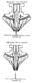
FIGS. 4A and 4B depict how the shaping gas tip is preferably interchangeable, which allows the impingement point of the powder to be defined relative to the beam diameter;
FIG. 5A shows the surface of an H13 tool steel sample deposited with a prior-art nozzle;
FIG. 5B shows the surface of an H13 tool steel sample deposited using the preferred nozzle described herein;
FIG. 6A is a photograph of a test specimen processed using a prior-art nozzle; and
FIG. 6B is a photograph of a test specimen processed using the inventive nozzle.
A nozzle assembly according to the invention is depicted in FIG. 1. The preferred embodiment includes five major components, as follows: a main body 102, inner tip housing 104, an inner tip 106, an outer shaping gas tip 108, and a cooling passage collar 110. The body is preferably machined out of a copper alloy for optimal thermal conductivity, and the surfaces of the nozzle that are exposed to the powder flow are preferably electroplated with hard chromium to provide a wear-resistant surface against highly abrasive tool steel powders. Since the nozzle is exposed to the intense heat of the melt pool and reflected laser beams, the copper also provides a high reflectivity to minimize heat generated from reflected laser beams being emitted from the weld pool and off of the workpiece.
The cooling circuit associated with the inventive nozzle is designed to optimize heat transfer from the inner and shaping gas tips, which are exposed to the highest temperatures during the deposition process. The heat is transferred into the nozzle coolant, typically a water/glycol mixture. Maximum cooling of these tips are necessary in preventing clogs from occurring, and increasing productivity of the process. Clogging of previous laser cladding nozzles was due to the nozzle tips having too high of an operating temperature. The metal powder being delivered through the nozzle, which flows along the tip, would begin to sinter to the tip. Once a few particles sinter, or cling, to the wall of the tip, the powder starts to accumulate behind the powder which is sintered to the nozzle tip. The powder building up causes a disruption in powder flow, resulting in uneven non concentric flow to the weld pool. The sintered powder is also exposed to reflected laser light, which can melt the sintered powder and also begin to melt the nozzle tip. With lower melting point materials the clogging of the nozzle is more pronounced and more frequent.
As best seen in FIG. 2, the nozzle includes a cooling supply line 202 and return line 204 for flow through the passageways. The supply and return are preferably located 180 degrees apart from one another at the entry and exit on the nozzle, thereby establishing a uniform flow about the center of the nozzle. Once the coolant enters the nozzle supply line, flow is diverted in two directions inside the nozzle into two passageways, or relieves, inside of the nozzle assembly. One of the passageways allows coolant to flow around the inner tip housing. The heat is transferred out of the inner tip towards the cooling passageway and into the coolant.
The coolant flows through abrupt 90 degree channels causing turbulent flow, which improves the transfer rate. The second passageway surrounds the entire nozzle. It contains a larger volume of coolant than the first passageway, because there is more material to transfer the heat through. The second passageway primarily cools the shaping gas tip and the main body of the nozzle. The secondary passageway is contained by the main body of the nozzle and a collar which is removable for maintenance. The coolant enters into the second passageway through abrupt 90 degree channels, and the surface of the nozzle main body is knurled on the cooling passageway walls, both causing turbulent flow. The shaping gas tip is threaded and torqued into the main body, and also seats on the machined face of the main body. Heat is transferred across those surfaces through the main body and into the coolant. The inventive nozzle facilitates continuous processing without any clogging problems, including the processing of low melting point materials such as Tin or Aluminum.
High laser power density is often required when processing refractory materials such as pure tungsten (W). The preferred nozzle therefore also utilizes temperature monitoring of the inner tip and shaping gas tip. The temperature of each is monitored by separate thermocouples, which the signal is an input to the CNC controls used to define a normal operating temperature range.
If the temperature detected is greater than the range defined in the CNC controls, the CNC will stop the process or send and alarm/warning. An increase in temperature of the inner or shaping gas tip exceeding the normal operating temperature is either caused due to a clog, laser beam alignment problem (laser beam is clipping the inner tip of the nozzle), or coolant flow problem. In the event the temperature detected is greater than the maximum of the normal operating range, the CNC controls stop the process. This prevents any loss in material deposition quality, or possible damage to equipment.
The normal operating temperature range was determined by running several tests to find the minimum and maximum temperatures with all process parameters defined. The coolant temperature flowing through the nozzle is 70° F. [+4° F.]. The normal operating temperature range of the DMD™ Nozzle inner tip=150° F.-400° F., and the shaping gas tip=150° F.-350° F. [during the processing of tool steels]. If the temperature exceeds 400° F. or greater the process is stopped. Measured temperature of inner tip when clog occurs=600° F.+, measured temperature when laser beam clips inner tip=700° F.+.
Returning to FIG. 1, the assembly receives powder flow from a powder splitter that evenly distributes powder flow into a plurality of tubes 112 (only two of which are visible in FIG. 1). The powder is controlled at a defined feed rate, and is carried with an inert gas at a controlled flow rate. The powder tubes, preferably four in number, enter into the top of the nozzle spaced every 90 degrees. The powder continues through four lines in the nozzle, which are at a decline, relative to horizontal.
The powder exits the lines into a chamber 120. The chamber is a cylindrical cavity in the nozzle that surrounds the inner tip 106 which, in turn, surrounds the laser beam. As the powder enters the chamber, it drops down through the chamber along the walls of the inner tip. It then bounces off a radial ring along the wall of the inner tip. This forces the powder to follow the internal angle of the shaping gas tip, at the same time evenly distributing powder concentrically on the inside diameter of the shaping gas tip. The powder exits, between the inner and outer, “shaping gas,” tip in a cone shape 130 that surrounding the laser beam.
The laser beam is focused through the center of the inner tip. The outer, or shaping, tip provides gas flow concentric to the powder flow and beam. The “shaping gas” tip, best seen in FIG. 3, is preferably comprised of a plurality of evenly spaced ports around the diameter of the outer tip. Sixteen such ports are used in the preferred embodiment. The port length, diameter, and angle are defined by a predetermined flow calculation. The gas is delivered to the nozzle by tubes 302, which supplies a gland of predetermined volume within the nozzle. This cavity is the supply for the gas ports through the shaping gas tip.
The gas exits the tip in a laminar flow condition. The gas exits the outer tip and directs the flow of powder resulting in the powder impinging to the beam diameter that is desired. Hence the name “shaping gas.” This causes the powder density at the operating beam diameter to increase, due to the flow of powder becoming concentrated by the shaping gas. As a result the process, or deposition, efficiencies are increased, and a lower powder feed rate can be used.
The shaping gas used is an inert gas, typically argon and/or helium, so it also provides shielding for the melt pool. The gas flow rate is defined and monitored through a metering valve system. The shaping gas tip of the inventive nozzle is also interchangeable, which allows the stand-off away from the work piece to be changed. The inner tip is also interchangeable and adjustable can be set up to operate at a plurality of distances from the workpiece, preferably in a range of 11.6 to 28 mm. The ability to change the stand-off from the workpiece creates increased flexibility for applications which sometimes require additional clearances to perform direct metal deposition. The entire assembly is independently adjustable up and down relative to the focal point of the laser beam, so the same beam diameter can be maintained through the stand-off range.
The standard nozzle set up utilizes the 11.6 mm stand-off, where minimal or no clearances are required. The 11.6 mm stand-off results in the highest powder efficiencies. The 28.0 mm stand-off is typically used in deposition repair processes which need to be performed in a cavity where additional clearances are required to avoid collisions or interferences. FIG. 4A shows the nozzle in the 11.6 mm stand-off configuration, whereas FIG. 4B shows the nozzle in the 28.0 mm stand-off configuration
Use of the inventive nozzle improves the metallurgical properties of the materials being deposited. Due to the fact that the powder is shaped to specified beam diameter, the powder is more concentrated and uniformly spaced and distributed to the melt pool, which is generated by the laser. This results in very high material density, reduction in porosity. The additional inert shaping gas flow, which is directed to the melt pool, eliminates oxides in the composition of the material being deposited. The shaping gas also provides enough localized shielding of the melt pool, as deposition takes place, preventing the need for any additional inert atmosphere for the processing of tool steels.
FIG. 5A shows the surface of H13 tool steel deposited with a prior-art nozzle manufactured by Quantum Laser Corp. Magnification is 100× with a 5% nital etch. Note the high degree of porosity. FIG. 5B shows the surface of H13 tool steel deposited using the preferred embodiment described herein. Again, magnification is 100× with a 5% nital etch. Note the dense, fine martinsitic grain structure. FIG. 6A is a photograph of a test specimen processed using a prior-art nozzle. Note the rough surface quality. FIG. 6B is a photograph of a test specimen processed using the inventive nozzle. The material in both cases is H13 tool steel. The sample of FIG. 6B measures 60 by 60 mm.
The inventive nozzle also has much greater process efficiencies associated with powder utilization. As previously noted, other powder nozzles used in laser cladding or deposition processes have very low powder efficiencies. Typical powder utilization efficiencies of existing processes range between 11-15%. The efficiency is the percentage of the amount powder being deposited relative to the amount of powder which is being delivered to the melt pool by the nozzle. This means only 11-15% of the powder being delivered is used during deposition. The low efficiency causes excess powder on the surface of the workpiece, increased frequency of adding material to the storage device or powder feeder, increased amounts of material to be removed or reclaimed from the processing, or work, table. The following test criteria were performed to determine the improvements using the inventive nozzle in comparison with the Quantum Laser cladding nozzle.
Powder Efficiency Test:
This test was performed to calculate the powder efficiency of the process using the DMD™ Nozzle. The following process parameters were used to define the test:
| Material Type: | H13 | Tool Steel |
| Material Density: | 7.8 | g/cc [0.282 lb/in3] |
| Deposition Geometry: | 60 | mm × 60 mm [2.36″ × 2.36″] |
| Layer Thickness: | 0.38 | mm [0.015″] |
| Deposition Bead Width: | 1.20 | mm [0.047″] |
| Bead Overlap: | 0.40 | mm [0.016″] or 0.80 mm stepover |
| CNC Velocity: | 600 | mm/m [23.6 in/min] |
| Powder Feed Rate: | 3.15 | g/m |
| Total Number of Layers | 30 | |
| Test Data: Substrate Mass | 1080 | grams [2.38 lb] |
| (Before Improvement): | ||
| Actual Deposition Geometry: | 61.2 | mm × 61.2 mm × 11.42 mm |
| Total Mass (Post-DMD ™): | 1410 | grams [3.117 lb] |
| DMD ™ Mass: | 330 | grams [0.736 lb] |
| DMD ™ Beam On Time: | 240 | minutes |
| Total DMD ™ Volume: | 42.77 | cc [2.61 in3] |
Material Deposition Rate=(DMD™ Mass)/(DMD™ Beam On Time)=(330 g/240 min)=1.375 g/m 
As the above results indicate, the powder efficiency using the inventive nozzle is greatly improved. Using the inventive nozzle, the deposition rate was increased one and one half (1.5) times what was previously achieved using the prior art nozzle. The following is an overview comparing the inventive nozzle versus the Quantum Laser nozzle:
| DMD ™ Nozzle | Quantum Laser Nozzle | |
| Deposition Rate | 1.375 | g/m [0.645 in3/hr] | 0.917 | g/m [0.430 |
| in3/hr] | ||||
| Powder Efficiency | 43.7% | 11.0% | ||
| Powder Feed Rate | 3.15 | g/m [0.416 lb/hr] | 5.5 | g/m [0.728 |
| lb/hr] | ||||
The increase in efficiency is primarily due to the control of the shaping gas. The “shaping gas” tip is comprised of a plurality of evenly spaced ports around the diameter of the outer tip, preferably 16 in number. The port length, diameter, and angle are defined by a predetermined flow calculation. As the powder flows out of the nozzle the shaping gas, typically an inert gas such as argon, causes the powder to focus to a point based on the angle the laminar flow of gas is exiting the 16 ports. The powder intersects at the defined laser beam diameter. This results in a more concentrated and focused conical shape of powder.
The inventive nozzle also improves surface quality, again primarily due to the shaping gas concentrating and containing the powder locally to the laser beam diameter that is being utilized. The vertical and horizontal surfaces are more consistent and accurate that existing laser cladding or deposition nozzles. The following is a comparison of the inventive nozzle versus the Quantum Laser nozzle in terms of surface quality:
| DMD ™ Nozzle | Quantum Laser Nozzle | ||
| Horizontal Surfaces | +0.003″ to +0.005″ | +0.006″ to +0.009″ |
| Vertical | +0.001″ to +0.003″ | +0.004″ to +0.010″ |
| Flatness | +0.002 | +0.007 |
Overall, the improved reliability and maintainability. The following items describe the functions which improve reliability, and allow for easy maintenance:
Interchangeable parts allows for multiple configurations.
Assembly is fully adjustable in the Z-axis (horizontal). Required for changing beam diameters and variable stand off from the workpiece
Spanner wrenches are used to assemble/disassemble.
All powder feed, inert gas, and water lines are connected to the nozzle using quick disconnect compression fittings.
All powder feed, inert gas, and water lines are orientated to avoid any exposure to laser reflections from the melt pool.
Improved cooling to eliminate occurrences of clogging or overheating.
Hard Chromium plating on surfaces exposed to highly abrasive processing powders.
If damage occurs to the nozzle, the individual component can be replaced that is damaged versus the entire assembly.
Claims (19)
1. A nozzle assembly particularly suited to direct metal deposition, comprising:
a body having a central axis and a distal end terminating in a distal tip, the distal tip including a conical end against which the powder is urged prior to exiting the body to assist in directing the powder to the localized point of the workpiece;
a laser beam aligned with the central axis and emerging from the distal tip;
a gas-carried powder feed path terminating in one or more powder outlets arranged in a first concentric ring surrounding the laser beam;
a shaping-gas inlet and one or more shaping-gas outlets arranged in a second concentric ring surrounding the laser beam; and
wherein the construction of the body is such that the laser beam, powder, and shaping gas all converge substantially within a localized region of a workpiece spaced apart from the distal tip at a working distance.
2. The nozzle assembly of claim 1 , wherein:
the body is constructed out of copper, a copper alloy, or other highly thermally conductive martial; and
wherein the surfaces of the body exposed to powder flow are electroplated with hard chromium.
3. The nozzle assembly of claim 1 , wherein the surfaces of the body exposed to powder flow are electroplated with hard chromium.
4. The nozzle assembly of claim 1 , wherein the shaping gas exits the body in a laminar flow condition.
5. The nozzle assembly of claim 1 , wherein at least a portion of the distal tip is adjustable to alter the working distance.
6. The nozzle assembly of claim 1 , wherein the working distance is adjustable between 10 and 30 mm.
7. The nozzle assembly of claim 1 , further including a coolant input and output and a cooling circuit within the body that promotes turbulent flow of the coolant.
8. The nozzle assembly of claim 1 , further including one or more contact thermocouples associated with terminating the operation of the nozzle or generating an alarm if a preset temperature is reached.
9. The nozzle assembly of claim 1 , wherein the body is constructed out of a highly thermally conductive material.
10. The nozzle assembly of claim 1 , wherein the material is copper or an alloy thereof.
11. A nozzle assembly particularly suited to direct metal deposition, comprising:
a body having a central axis and a distal end terminating in a distal tip;
a laser beam aligned with the central axis and emerging from the distal tip;
a coolant in put and output and a cooling circuit within the body that promotes turbulent flow of the coolant therewithin;
one or more contact thermocouples associated with terminating the operation of the nozzle or generating an alarm if a preset temperature is reached;
a gas-carried powder feed path terminating in one or more powder outlets arranged in a first concentric ring surrounding the laser beam;
a shaping-gas inlet and one or more shaping-gas outlets arranged in a second concentric ring surrounding the laser beam;
the construction of the body is such that the laser beam, powder, and shaping gas all converge substantially within a localized region of a workpiece spaced apart from the distal tip at a working distance; and
wherein at least a portion of the distal tip is adjustable to alter the working distance.
12. The nozzle assembly of claim 11 , wherein the shaping gas exits the body in a laminar flow condition.
13. he nozzle assembly of claim 11 , wherein the working distance is adjustable between 10 and 30 mm.
14. A nozzle assembly particularly suited to direct metal deposition, comprising:
a body having a central axis and a distal end terminating in a distal tip;
a laser beam aligned with the central axis and emerging from the distal tip;
a coolant input and output and a cooling circuit within the body that promotes turbulent flow of the coolant;
a powder inlet and one or more powder outlets arranged in a first concentric ring surrounding the laser beam;
a shaping-gas inlet and one or more shaping-gas outlets arranged in a second concentric ring surrounding the laser beam; and
an inner tip surrounding the laser beam, the distal tip including conical end against which the pow der is urged prior to exiting the body, such that the laser beam, powder, and shaping gas all converge substantially within a localized region of a workpiece spaced apart from the distal tip at a working distance.
15. The nozzle assembly of claim 14 , wherein the working distance is adjustable bet ween 10 and 30 mm.
16. The nozzle assembly of claim 14 , further including one or more contact thermocouples in communication with a controller for terminating the operation of the nozzle or generating an alarm if a desired operating condition is not met.
17. The nozzle assembly of claim 14 , wherein:
the body is constructed out of copper, a copper alloy, or other highly thermally conductive material; and
wherein the surfaces of the body exposed to powder flow are electroplated with hard chromium.
18. The nozzle assembly of claim 14 , wherein the shaping gas exits the body in a laminar flow condition.
19. The nozzle assembly of claim 14 , wherein at least a portion of the distal tip is adjustable to alter the working distance.
Priority Applications (1)
| Application Number | Priority Date | Filing Date | Title |
|---|---|---|---|
| US09/671,535 US6534745B1 (en) | 1999-09-27 | 2000-09-27 | Nozzle particularly suited to direct metal deposition |
Applications Claiming Priority (2)
| Application Number | Priority Date | Filing Date | Title |
|---|---|---|---|
| US15620399P | 1999-09-27 | 1999-09-27 | |
| US09/671,535 US6534745B1 (en) | 1999-09-27 | 2000-09-27 | Nozzle particularly suited to direct metal deposition |
Publications (1)
| Publication Number | Publication Date |
|---|---|
| US6534745B1 true US6534745B1 (en) | 2003-03-18 |
Family
ID=26852965
Family Applications (1)
| Application Number | Title | Priority Date | Filing Date |
|---|---|---|---|
| US09/671,535 Expired - Lifetime US6534745B1 (en) | 1999-09-27 | 2000-09-27 | Nozzle particularly suited to direct metal deposition |
Country Status (1)
| Country | Link |
|---|---|
| US (1) | US6534745B1 (en) |
Cited By (57)
| Publication number | Priority date | Publication date | Assignee | Title |
|---|---|---|---|---|
| US20030052098A1 (en) * | 2001-05-23 | 2003-03-20 | Gi-Heon Kim | Method and apparatus for cutting substrate using coolant |
| US20040164059A1 (en) * | 2002-11-29 | 2004-08-26 | Alstom Technology Ltd | Method for fabricating, modifying or repairing of single crystal or directionally solidified articles |
| US20050056628A1 (en) * | 2003-09-16 | 2005-03-17 | Yiping Hu | Coaxial nozzle design for laser cladding/welding process |
| US20050061790A1 (en) * | 2003-08-09 | 2005-03-24 | Martin Lambert | Laser processing nozzle coupling |
| EP1535696A1 (en) * | 2003-11-25 | 2005-06-01 | CESI-Centro Elettrotecnico Sperimentale Italiano Giacinto Motta S.p.A. | Apparatus for coating tubes by means of laser beam and relative method |
| US20050133486A1 (en) * | 2003-12-19 | 2005-06-23 | Baker Martin C. | Hand-held laser welding wand having removable filler media delivery extension tips |
| US20050212694A1 (en) * | 2004-03-26 | 2005-09-29 | Chun-Ta Chen | Data distribution method and system |
| US7001672B2 (en) | 2003-12-03 | 2006-02-21 | Medicine Lodge, Inc. | Laser based metal deposition of implant structures |
| US20060049153A1 (en) * | 2004-09-08 | 2006-03-09 | Cahoon Christopher L | Dual feed laser welding system |
| US20060065650A1 (en) * | 2004-09-30 | 2006-03-30 | Wen Guo | Compact coaxial nozzle for laser cladding |
| US20060078738A1 (en) * | 2003-06-04 | 2006-04-13 | Mitsubishi Denki Kabushiki Kaisha | Coating formed on base metal surface, heat-resistant machinery part, nozzle for processing machine, contact tip for welding, method of forming coating, method of manufacturing heat-resistant machinery part, method of manufacturing nozzle for processing machine, and method of manufacturing contact tip for welding |
| US20060266740A1 (en) * | 2004-02-03 | 2006-11-30 | Toyota Jidosha Kabushiki Kaisha | Powder metal cladding nozzle |
| US20060266745A1 (en) * | 2005-05-31 | 2006-11-30 | Honeywell International, Inc. | Gas shielding apparatus and method of use |
| WO2007022567A1 (en) * | 2005-08-23 | 2007-03-01 | Hardwear Pty Ltd | Powder delivery nozzle |
| US20070193981A1 (en) * | 2006-02-22 | 2007-08-23 | General Electric Company | Nozzle for laser net shape manufacturing |
| US20070202351A1 (en) * | 2003-12-03 | 2007-08-30 | Justin Daniel F | Laser based metal deposition (LBMD) of implant structures |
| US20070205184A1 (en) * | 2006-01-30 | 2007-09-06 | Jyoti Mazumder | High-speed, ultra precision manufacturing station that combines direct metal deposition and edm |
| US20070253810A1 (en) * | 2005-11-15 | 2007-11-01 | Snecma | Method of making a wiper for a sealing labyrinth, and a thermomechanical part and a turbomachine including such a wiper |
| US20080295313A1 (en) * | 2007-05-29 | 2008-12-04 | Shih-Ta Chang | Manufacturing method for golf club head |
| US20090057278A1 (en) * | 2007-09-05 | 2009-03-05 | Steffen Nowotny | Machining head with integrated powder supply for deposition welding using laser radiation |
| WO2009077870A2 (en) * | 2007-10-10 | 2009-06-25 | Ronald Peter Whitfield | Laser cladding device with an improved nozzle |
| US20090314136A1 (en) * | 2008-06-23 | 2009-12-24 | The Stanley Works | Method of manufacturing a blade |
| US20100024200A1 (en) * | 2008-07-30 | 2010-02-04 | Hydraforce, Inc. | Method for making a solenoid actuator |
| US7951412B2 (en) | 2006-06-07 | 2011-05-31 | Medicinelodge Inc. | Laser based metal deposition (LBMD) of antimicrobials to implant surfaces |
| US20110300306A1 (en) * | 2009-12-04 | 2011-12-08 | The Regents Of The University Of Michigan | Coaxial laser assisted cold spray nozzle |
| US20120145683A1 (en) * | 2010-12-13 | 2012-06-14 | Hitachi, Ltd. | Laser processing system and overlay welding method |
| US20120214017A1 (en) * | 2011-02-22 | 2012-08-23 | Pourin Welding Engineering Co., Ltd. | Weld Overlay Structure and a Method of Providing a Weld Overlay Structure |
| US20130087547A1 (en) * | 2011-10-05 | 2013-04-11 | Applied Materials, Inc. | Particle control in laser processing systems |
| US20140026730A1 (en) * | 2009-03-26 | 2014-01-30 | Bhaskar Dutta | Method of manufacturing of cutting knives using direct metal deposition |
| US8769833B2 (en) | 2010-09-10 | 2014-07-08 | Stanley Black & Decker, Inc. | Utility knife blade |
| US8800480B2 (en) | 2007-10-10 | 2014-08-12 | Ronald Peter Whitfield | Laser cladding device with an improved nozzle |
| US20150021379A1 (en) * | 2013-07-16 | 2015-01-22 | Illinois Tool Works Inc. | Additive manufacturing system for joining and surface overlay |
| US20150165559A1 (en) * | 2013-12-13 | 2015-06-18 | Jens Guenter Gaebelein | Methods and apparatus to perform a liquid-jet guided laser process and to simplify the maintenance thereof |
| US20150196975A1 (en) * | 2014-01-14 | 2015-07-16 | Toyota Jidosha Kabushiki Kaisha | Powder overlay nozzle |
| US20160121427A1 (en) * | 2014-10-31 | 2016-05-05 | Prima Power Laserdyne, Llc | Cross jet laser welding nozzle |
| US9352420B2 (en) | 2007-10-10 | 2016-05-31 | Ronald Peter Whitfield | Laser cladding device with an improved zozzle |
| US20160243638A1 (en) * | 2015-02-25 | 2016-08-25 | Hobart Brothers Company | Systems and methods for additive manufacturing using aluminum metal-cored wire |
| US20170050268A1 (en) * | 2015-03-24 | 2017-02-23 | Technology Research Association For Future Additive Manufacturing | Processing nozzle, processing head, and machining apparatus |
| US20170120392A1 (en) * | 2015-10-30 | 2017-05-04 | Hypertherm, Inc. | Water Cooling of Laser Components |
| US20170120517A1 (en) * | 2014-03-18 | 2017-05-04 | Kabushiki Kaisha Toshiba | Nozzle and layered object manufacturing apparatus |
| US9650537B2 (en) | 2014-04-14 | 2017-05-16 | Ut-Battelle, Llc | Reactive polymer fused deposition manufacturing |
| CN107498042A (en) * | 2016-06-14 | 2017-12-22 | 特斯蒂亚有限责任公司 | 3D printing method and 3D printing device |
| WO2018044869A1 (en) * | 2016-08-29 | 2018-03-08 | Katon Andrew | Nozzle technology for ultra-variable manufacturing systems |
| US10119195B2 (en) | 2009-12-04 | 2018-11-06 | The Regents Of The University Of Michigan | Multichannel cold spray apparatus |
| US10124531B2 (en) | 2013-12-30 | 2018-11-13 | Ut-Battelle, Llc | Rapid non-contact energy transfer for additive manufacturing driven high intensity electromagnetic fields |
| US10201877B2 (en) | 2011-10-26 | 2019-02-12 | Titanova Inc | Puddle forming and shaping with primary and secondary lasers |
| US20190047088A1 (en) * | 2017-08-09 | 2019-02-14 | Formalloy, Llc | Laser metal deposition head |
| US10328523B2 (en) | 2014-07-11 | 2019-06-25 | Rolls-Royce Corporation | Fluted additive manufacturing deposition head design |
| US10384264B2 (en) | 2015-01-16 | 2019-08-20 | Rolls-Royce Corporation | Compact axially translational powder deposition head |
| US10773268B2 (en) * | 2015-12-31 | 2020-09-15 | Ecole Centrale De Nantes | Device for additive manufacturing by spraying and fusion of powder |
| US10792682B2 (en) | 2017-10-02 | 2020-10-06 | Illinois Tool Works Inc. | Metal manufacturing systems and methods using mechanical oscillation |
| CN112011794A (en) * | 2020-08-31 | 2020-12-01 | 李志华 | Laser cladding device and method for numerical control spindle abrasion taper hole |
| US10974337B2 (en) | 2015-08-17 | 2021-04-13 | Illinois Tool Works Inc. | Additive manufacturing systems and methods |
| CN114258331A (en) * | 2019-08-22 | 2022-03-29 | 赛峰飞机发动机公司 | Laser metal deposition system |
| US11370068B2 (en) * | 2015-02-25 | 2022-06-28 | Hobart Brothers Llc | Systems and methods for additive manufacturing using aluminum metal-cored wire |
| US11433488B2 (en) * | 2018-03-15 | 2022-09-06 | Gkn Aerospace St. Louis Llc | Gas dispersion for additive manufacturing |
| US11813671B2 (en) | 2020-01-27 | 2023-11-14 | Rolls-Royce Corporation | Microtextured nozzle for directed energy deposition with greater than 100 features per square millimeter |
Citations (13)
| Publication number | Priority date | Publication date | Assignee | Title |
|---|---|---|---|---|
| US4724299A (en) | 1987-04-15 | 1988-02-09 | Quantum Laser Corporation | Laser spray nozzle and method |
| US4803335A (en) | 1986-01-07 | 1989-02-07 | Quantum Laser Corporation | Gas shroud and method |
| US4804815A (en) | 1987-06-01 | 1989-02-14 | Quantum Laser Corporation | Process for welding nickel-based superalloys |
| US5321228A (en) * | 1991-06-24 | 1994-06-14 | Andreas Krause | Nozzle for the surface treatment of metal workpieces |
| US5418350A (en) * | 1992-01-07 | 1995-05-23 | Electricite De Strasbourg (S.A.) | Coaxial nozzle for surface treatment by laser irradiation, with supply of materials in powder form |
| US5453329A (en) | 1992-06-08 | 1995-09-26 | Quantum Laser Corporation | Method for laser cladding thermally insulated abrasive particles to a substrate, and clad substrate formed thereby |
| US5477025A (en) | 1994-01-14 | 1995-12-19 | Quantum Laser Corporation | Laser nozzle |
| US5477026A (en) * | 1994-01-27 | 1995-12-19 | Chromalloy Gas Turbine Corporation | Laser/powdered metal cladding nozzle |
| US5837960A (en) * | 1995-08-14 | 1998-11-17 | The Regents Of The University Of California | Laser production of articles from powders |
| US6042019A (en) * | 1996-05-17 | 2000-03-28 | Sulzer Metco (Us) Inc. | Thermal spray gun with inner passage liner and component for such gun |
| US6046426A (en) * | 1996-07-08 | 2000-04-04 | Sandia Corporation | Method and system for producing complex-shape objects |
| US6122564A (en) | 1998-06-30 | 2000-09-19 | Koch; Justin | Apparatus and methods for monitoring and controlling multi-layer laser cladding |
| US6268584B1 (en) * | 1998-01-22 | 2001-07-31 | Optomec Design Company | Multiple beams and nozzles to increase deposition rate |
-
2000
- 2000-09-27 US US09/671,535 patent/US6534745B1/en not_active Expired - Lifetime
Patent Citations (13)
| Publication number | Priority date | Publication date | Assignee | Title |
|---|---|---|---|---|
| US4803335A (en) | 1986-01-07 | 1989-02-07 | Quantum Laser Corporation | Gas shroud and method |
| US4724299A (en) | 1987-04-15 | 1988-02-09 | Quantum Laser Corporation | Laser spray nozzle and method |
| US4804815A (en) | 1987-06-01 | 1989-02-14 | Quantum Laser Corporation | Process for welding nickel-based superalloys |
| US5321228A (en) * | 1991-06-24 | 1994-06-14 | Andreas Krause | Nozzle for the surface treatment of metal workpieces |
| US5418350A (en) * | 1992-01-07 | 1995-05-23 | Electricite De Strasbourg (S.A.) | Coaxial nozzle for surface treatment by laser irradiation, with supply of materials in powder form |
| US5453329A (en) | 1992-06-08 | 1995-09-26 | Quantum Laser Corporation | Method for laser cladding thermally insulated abrasive particles to a substrate, and clad substrate formed thereby |
| US5477025A (en) | 1994-01-14 | 1995-12-19 | Quantum Laser Corporation | Laser nozzle |
| US5477026A (en) * | 1994-01-27 | 1995-12-19 | Chromalloy Gas Turbine Corporation | Laser/powdered metal cladding nozzle |
| US5837960A (en) * | 1995-08-14 | 1998-11-17 | The Regents Of The University Of California | Laser production of articles from powders |
| US6042019A (en) * | 1996-05-17 | 2000-03-28 | Sulzer Metco (Us) Inc. | Thermal spray gun with inner passage liner and component for such gun |
| US6046426A (en) * | 1996-07-08 | 2000-04-04 | Sandia Corporation | Method and system for producing complex-shape objects |
| US6268584B1 (en) * | 1998-01-22 | 2001-07-31 | Optomec Design Company | Multiple beams and nozzles to increase deposition rate |
| US6122564A (en) | 1998-06-30 | 2000-09-19 | Koch; Justin | Apparatus and methods for monitoring and controlling multi-layer laser cladding |
Cited By (99)
| Publication number | Priority date | Publication date | Assignee | Title |
|---|---|---|---|---|
| US20030052098A1 (en) * | 2001-05-23 | 2003-03-20 | Gi-Heon Kim | Method and apparatus for cutting substrate using coolant |
| US20040164059A1 (en) * | 2002-11-29 | 2004-08-26 | Alstom Technology Ltd | Method for fabricating, modifying or repairing of single crystal or directionally solidified articles |
| US6998568B2 (en) * | 2002-11-29 | 2006-02-14 | Alstom Technology Ltd | Method for fabricating, modifying or repairing of single crystal or directionally solidified articles |
| US20060078738A1 (en) * | 2003-06-04 | 2006-04-13 | Mitsubishi Denki Kabushiki Kaisha | Coating formed on base metal surface, heat-resistant machinery part, nozzle for processing machine, contact tip for welding, method of forming coating, method of manufacturing heat-resistant machinery part, method of manufacturing nozzle for processing machine, and method of manufacturing contact tip for welding |
| US20050061790A1 (en) * | 2003-08-09 | 2005-03-24 | Martin Lambert | Laser processing nozzle coupling |
| US7273997B2 (en) * | 2003-08-09 | 2007-09-25 | Trumpf Werkzeugmaschinen Gmbh + Co. Kg | Laser processing nozzle coupling |
| US20050056628A1 (en) * | 2003-09-16 | 2005-03-17 | Yiping Hu | Coaxial nozzle design for laser cladding/welding process |
| EP1535696A1 (en) * | 2003-11-25 | 2005-06-01 | CESI-Centro Elettrotecnico Sperimentale Italiano Giacinto Motta S.p.A. | Apparatus for coating tubes by means of laser beam and relative method |
| US7666522B2 (en) | 2003-12-03 | 2010-02-23 | IMDS, Inc. | Laser based metal deposition (LBMD) of implant structures |
| US7632575B2 (en) | 2003-12-03 | 2009-12-15 | IMDS, Inc. | Laser based metal deposition (LBMD) of implant structures |
| US20070202351A1 (en) * | 2003-12-03 | 2007-08-30 | Justin Daniel F | Laser based metal deposition (LBMD) of implant structures |
| US20060073356A1 (en) * | 2003-12-03 | 2006-04-06 | Justin Daniel F | Laser based metal deposition (LBMD) of implant structures |
| US7001672B2 (en) | 2003-12-03 | 2006-02-21 | Medicine Lodge, Inc. | Laser based metal deposition of implant structures |
| US7030337B2 (en) | 2003-12-19 | 2006-04-18 | Honeywell International, Inc. | Hand-held laser welding wand having removable filler media delivery extension tips |
| US20050133486A1 (en) * | 2003-12-19 | 2005-06-23 | Baker Martin C. | Hand-held laser welding wand having removable filler media delivery extension tips |
| US20060266740A1 (en) * | 2004-02-03 | 2006-11-30 | Toyota Jidosha Kabushiki Kaisha | Powder metal cladding nozzle |
| US7626136B2 (en) * | 2004-02-03 | 2009-12-01 | Toyota Jidosha Kabushiki Kaisha | Powder metal cladding nozzle |
| US20050212694A1 (en) * | 2004-03-26 | 2005-09-29 | Chun-Ta Chen | Data distribution method and system |
| US20060049153A1 (en) * | 2004-09-08 | 2006-03-09 | Cahoon Christopher L | Dual feed laser welding system |
| US7259353B2 (en) | 2004-09-30 | 2007-08-21 | Honeywell International, Inc. | Compact coaxial nozzle for laser cladding |
| US20060065650A1 (en) * | 2004-09-30 | 2006-03-30 | Wen Guo | Compact coaxial nozzle for laser cladding |
| US20060266745A1 (en) * | 2005-05-31 | 2006-11-30 | Honeywell International, Inc. | Gas shielding apparatus and method of use |
| WO2007022567A1 (en) * | 2005-08-23 | 2007-03-01 | Hardwear Pty Ltd | Powder delivery nozzle |
| US20080308538A1 (en) * | 2005-08-23 | 2008-12-18 | James Gordon Harris | Powder Delivery Nozzle |
| US7605346B2 (en) | 2005-08-23 | 2009-10-20 | Hardwear Pyt Ltd | Powder delivery nozzle |
| CN101291772B (en) * | 2005-08-23 | 2011-08-31 | 五金有限公司 | Powder delivery nozzle |
| US7836572B2 (en) * | 2005-11-15 | 2010-11-23 | Snecma | Method of making a wiper for a sealing labyrinth, and a thermomechanical part and a turbomachine including such a wiper |
| US20070253810A1 (en) * | 2005-11-15 | 2007-11-01 | Snecma | Method of making a wiper for a sealing labyrinth, and a thermomechanical part and a turbomachine including such a wiper |
| US20070205184A1 (en) * | 2006-01-30 | 2007-09-06 | Jyoti Mazumder | High-speed, ultra precision manufacturing station that combines direct metal deposition and edm |
| US8629368B2 (en) | 2006-01-30 | 2014-01-14 | Dm3D Technology, Llc | High-speed, ultra precision manufacturing station that combines direct metal deposition and EDM |
| US7358457B2 (en) | 2006-02-22 | 2008-04-15 | General Electric Company | Nozzle for laser net shape manufacturing |
| US20070193981A1 (en) * | 2006-02-22 | 2007-08-23 | General Electric Company | Nozzle for laser net shape manufacturing |
| EP1825948A3 (en) * | 2006-02-22 | 2010-03-10 | General Electric Company | Nozzle for laser net shape manufacturing |
| US7951412B2 (en) | 2006-06-07 | 2011-05-31 | Medicinelodge Inc. | Laser based metal deposition (LBMD) of antimicrobials to implant surfaces |
| US20080295313A1 (en) * | 2007-05-29 | 2008-12-04 | Shih-Ta Chang | Manufacturing method for golf club head |
| US20090057278A1 (en) * | 2007-09-05 | 2009-03-05 | Steffen Nowotny | Machining head with integrated powder supply for deposition welding using laser radiation |
| US8129657B2 (en) * | 2007-09-05 | 2012-03-06 | Fraunhofer-Gesellschaft Zur Foerderung Der Angewandten Forschung E.V. | Machining head with integrated powder supply for deposition welding using laser radiation |
| GB2452600B (en) * | 2007-09-05 | 2012-08-08 | Fraunhofer Ges Forschung | Machining head with integrated powder supply for deposition welding using laser radiation |
| WO2009077870A2 (en) * | 2007-10-10 | 2009-06-25 | Ronald Peter Whitfield | Laser cladding device with an improved nozzle |
| US8800480B2 (en) | 2007-10-10 | 2014-08-12 | Ronald Peter Whitfield | Laser cladding device with an improved nozzle |
| US8117985B2 (en) | 2007-10-10 | 2012-02-21 | Ronald Peter Whitfield | Laser cladding device with an improved nozzle |
| WO2009077870A3 (en) * | 2007-10-10 | 2011-04-28 | Ronald Peter Whitfield | Laser cladding device with an improved nozzle |
| GB2465950B (en) * | 2007-10-10 | 2012-10-03 | Ronald Peter Whitfield | Laser cladding device with an improved nozzle |
| US9352420B2 (en) | 2007-10-10 | 2016-05-31 | Ronald Peter Whitfield | Laser cladding device with an improved zozzle |
| US10065269B2 (en) | 2007-10-10 | 2018-09-04 | Ronald Peter Whitfield | Laser cladding device with an improved nozzle |
| US8505414B2 (en) | 2008-06-23 | 2013-08-13 | Stanley Black & Decker, Inc. | Method of manufacturing a blade |
| US20090314136A1 (en) * | 2008-06-23 | 2009-12-24 | The Stanley Works | Method of manufacturing a blade |
| US20100024200A1 (en) * | 2008-07-30 | 2010-02-04 | Hydraforce, Inc. | Method for making a solenoid actuator |
| US8253063B2 (en) | 2008-07-30 | 2012-08-28 | Hydraforce, Inc. | Method for making a solenoid actuator |
| US10160127B2 (en) * | 2009-03-26 | 2018-12-25 | Dm3D Technology, Llc | Method of manufacturing of cutting knives using direct metal deposition |
| US20140026730A1 (en) * | 2009-03-26 | 2014-01-30 | Bhaskar Dutta | Method of manufacturing of cutting knives using direct metal deposition |
| US10119195B2 (en) | 2009-12-04 | 2018-11-06 | The Regents Of The University Of Michigan | Multichannel cold spray apparatus |
| US9481933B2 (en) * | 2009-12-04 | 2016-11-01 | The Regents Of The University Of Michigan | Coaxial laser assisted cold spray nozzle |
| US20110300306A1 (en) * | 2009-12-04 | 2011-12-08 | The Regents Of The University Of Michigan | Coaxial laser assisted cold spray nozzle |
| US9393984B2 (en) | 2010-09-10 | 2016-07-19 | Stanley Black & Decker, Inc. | Utility knife blade |
| US8769833B2 (en) | 2010-09-10 | 2014-07-08 | Stanley Black & Decker, Inc. | Utility knife blade |
| US20120145683A1 (en) * | 2010-12-13 | 2012-06-14 | Hitachi, Ltd. | Laser processing system and overlay welding method |
| US8901453B2 (en) * | 2010-12-13 | 2014-12-02 | Hitachi, Ltd. | Laser processing system and overlay welding method |
| US20120214017A1 (en) * | 2011-02-22 | 2012-08-23 | Pourin Welding Engineering Co., Ltd. | Weld Overlay Structure and a Method of Providing a Weld Overlay Structure |
| US20130087547A1 (en) * | 2011-10-05 | 2013-04-11 | Applied Materials, Inc. | Particle control in laser processing systems |
| US9579750B2 (en) * | 2011-10-05 | 2017-02-28 | Applied Materials, Inc. | Particle control in laser processing systems |
| US10201877B2 (en) | 2011-10-26 | 2019-02-12 | Titanova Inc | Puddle forming and shaping with primary and secondary lasers |
| US10875116B2 (en) | 2013-07-16 | 2020-12-29 | Illinois Tool Works Inc. | Additive manufacturing heating control systems and methods |
| US10543549B2 (en) * | 2013-07-16 | 2020-01-28 | Illinois Tool Works Inc. | Additive manufacturing system for joining and surface overlay |
| US20150021379A1 (en) * | 2013-07-16 | 2015-01-22 | Illinois Tool Works Inc. | Additive manufacturing system for joining and surface overlay |
| US11833623B2 (en) | 2013-07-16 | 2023-12-05 | Illinois Tool Works Inc. | Additive manufacturing system for joining and surface overlay |
| US10940561B2 (en) * | 2013-12-13 | 2021-03-09 | Avonisys Ag | Methods and apparatus to perform a liquid-jet guided laser process and to simplify the maintenance thereof |
| US20150165559A1 (en) * | 2013-12-13 | 2015-06-18 | Jens Guenter Gaebelein | Methods and apparatus to perform a liquid-jet guided laser process and to simplify the maintenance thereof |
| US20180318959A1 (en) * | 2013-12-13 | 2018-11-08 | Avonisys Ag | Methods and apparatus to perform a liquid-jet guided laser process and to simplify the maintenance thereof |
| US10022820B2 (en) * | 2013-12-13 | 2018-07-17 | Avonisys Ag | Methods and apparatus to perform a liquid-jet guided laser process and to simplify the maintenance thereof |
| US10124531B2 (en) | 2013-12-30 | 2018-11-13 | Ut-Battelle, Llc | Rapid non-contact energy transfer for additive manufacturing driven high intensity electromagnetic fields |
| US9533373B2 (en) * | 2014-01-14 | 2017-01-03 | Toyota Jidosha Kabushiki Kaisha | Powder overlay nozzle |
| US20150196975A1 (en) * | 2014-01-14 | 2015-07-16 | Toyota Jidosha Kabushiki Kaisha | Powder overlay nozzle |
| US20170120517A1 (en) * | 2014-03-18 | 2017-05-04 | Kabushiki Kaisha Toshiba | Nozzle and layered object manufacturing apparatus |
| US10543644B2 (en) * | 2014-03-18 | 2020-01-28 | Kabushiki Kaisha Toshiba | Nozzle and layered object manufacturing apparatus |
| US9650537B2 (en) | 2014-04-14 | 2017-05-16 | Ut-Battelle, Llc | Reactive polymer fused deposition manufacturing |
| US10328523B2 (en) | 2014-07-11 | 2019-06-25 | Rolls-Royce Corporation | Fluted additive manufacturing deposition head design |
| US20160121427A1 (en) * | 2014-10-31 | 2016-05-05 | Prima Power Laserdyne, Llc | Cross jet laser welding nozzle |
| US10335899B2 (en) * | 2014-10-31 | 2019-07-02 | Prima Power Laserdyne | Cross jet laser welding nozzle |
| US10384264B2 (en) | 2015-01-16 | 2019-08-20 | Rolls-Royce Corporation | Compact axially translational powder deposition head |
| US10421159B2 (en) * | 2015-02-25 | 2019-09-24 | Hobart Brothers Llc | Systems and methods for additive manufacturing using aluminum metal-cored wire |
| US11370068B2 (en) * | 2015-02-25 | 2022-06-28 | Hobart Brothers Llc | Systems and methods for additive manufacturing using aluminum metal-cored wire |
| US20160243638A1 (en) * | 2015-02-25 | 2016-08-25 | Hobart Brothers Company | Systems and methods for additive manufacturing using aluminum metal-cored wire |
| US20170050268A1 (en) * | 2015-03-24 | 2017-02-23 | Technology Research Association For Future Additive Manufacturing | Processing nozzle, processing head, and machining apparatus |
| US10974337B2 (en) | 2015-08-17 | 2021-04-13 | Illinois Tool Works Inc. | Additive manufacturing systems and methods |
| US10525554B2 (en) * | 2015-10-30 | 2020-01-07 | Hypertherm, Inc. | Water cooling of laser components |
| US20170120392A1 (en) * | 2015-10-30 | 2017-05-04 | Hypertherm, Inc. | Water Cooling of Laser Components |
| US10773268B2 (en) * | 2015-12-31 | 2020-09-15 | Ecole Centrale De Nantes | Device for additive manufacturing by spraying and fusion of powder |
| CN107498042A (en) * | 2016-06-14 | 2017-12-22 | 特斯蒂亚有限责任公司 | 3D printing method and 3D printing device |
| WO2018044869A1 (en) * | 2016-08-29 | 2018-03-08 | Katon Andrew | Nozzle technology for ultra-variable manufacturing systems |
| US11858068B2 (en) | 2017-08-09 | 2024-01-02 | Formalloy Technologies, Inc. | Laser metal deposition head |
| US10875123B2 (en) * | 2017-08-09 | 2020-12-29 | Formalloy Technologies, Inc. | Laser metal deposition head |
| US20190047088A1 (en) * | 2017-08-09 | 2019-02-14 | Formalloy, Llc | Laser metal deposition head |
| US10792682B2 (en) | 2017-10-02 | 2020-10-06 | Illinois Tool Works Inc. | Metal manufacturing systems and methods using mechanical oscillation |
| US11433488B2 (en) * | 2018-03-15 | 2022-09-06 | Gkn Aerospace St. Louis Llc | Gas dispersion for additive manufacturing |
| CN114258331A (en) * | 2019-08-22 | 2022-03-29 | 赛峰飞机发动机公司 | Laser metal deposition system |
| US11813671B2 (en) | 2020-01-27 | 2023-11-14 | Rolls-Royce Corporation | Microtextured nozzle for directed energy deposition with greater than 100 features per square millimeter |
| CN112011794B (en) * | 2020-08-31 | 2022-08-23 | 河北加迈激光科技有限公司 | Laser cladding device and method for numerical control spindle abrasion taper hole |
| CN112011794A (en) * | 2020-08-31 | 2020-12-01 | 李志华 | Laser cladding device and method for numerical control spindle abrasion taper hole |
Similar Documents
| Publication | Publication Date | Title |
|---|---|---|
| US6534745B1 (en) | Nozzle particularly suited to direct metal deposition | |
| US4724299A (en) | Laser spray nozzle and method | |
| US6881919B2 (en) | Powder feed nozzle for laser welding | |
| US11858068B2 (en) | Laser metal deposition head | |
| US6316744B1 (en) | Machining head and process for the surface machining of workpieces by means of a laser beam | |
| RU2317183C2 (en) | Manual powder-supplied torch for fusion laser welding | |
| KR100606476B1 (en) | Apparatus and methods for laser cladding | |
| US6423926B1 (en) | Direct-metal-deposition (DMD) nozzle fault detection using temperature measurements | |
| US11478881B2 (en) | Optical module having a device for automatically changing a collimation optic | |
| US20020065573A1 (en) | Direct metal deposition apparatus utilizing rapid-response diode laser source | |
| CA2009127A1 (en) | Laser welding apparatus and process | |
| EP2498935A1 (en) | Electron beam layer manufacturing using scanning electron monitored closed loop control | |
| US11927825B2 (en) | Exchangeable optical module for a laser machining machine | |
| Kumar et al. | Critical review of off-axial nozzle and coaxial nozzle for powder metal deposition | |
| CN110424011B (en) | Laser cladding powder feeding device | |
| KR100341489B1 (en) | Powder feeding apparatus for the laser-surface modification and laser direct material manufacturing systems | |
| US20040020625A1 (en) | Fabrication of customized die inserts using closed-loop direct metal deposition (DMD) | |
| US6518541B1 (en) | Duty cycle stabilization in direct metal deposition (DMD) systems | |
| US20180178326A1 (en) | Vacuum sls method for the additive manufacture of metallic components | |
| Nowotny et al. | Generative manufacturing and repair of metal parts through direct laser deposition using wire material | |
| CN103056363B (en) | Powder feeding mouth, the assembly manufactured for laser assisted additive and method | |
| CA3154058C (en) | Material feeding device | |
| Jayanth et al. | Modeling Of Laser Based Direct Metal Deposition Process | |
| US20230001641A1 (en) | Stock feeding device | |
| US20230146425A1 (en) | Material deposition unit for powder build-up welding |
Legal Events
| Date | Code | Title | Description |
|---|---|---|---|
| STCF | Information on status: patent grant |
Free format text: PATENTED CASE |
|
| CC | Certificate of correction | ||
| REMI | Maintenance fee reminder mailed | ||
| FPAY | Fee payment |
Year of fee payment: 4 |
|
| SULP | Surcharge for late payment | ||
| FPAY | Fee payment |
Year of fee payment: 8 |
|
| FPAY | Fee payment |
Year of fee payment: 12 |