US6526293B1 - Wireless communication apparatus having rechargeable battery - Google Patents
Wireless communication apparatus having rechargeable battery Download PDFInfo
- Publication number
- US6526293B1 US6526293B1 US09/092,010 US9201098A US6526293B1 US 6526293 B1 US6526293 B1 US 6526293B1 US 9201098 A US9201098 A US 9201098A US 6526293 B1 US6526293 B1 US 6526293B1
- Authority
- US
- United States
- Prior art keywords
- rechargeable battery
- charge
- charging
- light
- battery
- Prior art date
- Legal status (The legal status is an assumption and is not a legal conclusion. Google has not performed a legal analysis and makes no representation as to the accuracy of the status listed.)
- Expired - Lifetime
Links
Images


Classifications
-
- H—ELECTRICITY
- H02—GENERATION; CONVERSION OR DISTRIBUTION OF ELECTRIC POWER
- H02J—CIRCUIT ARRANGEMENTS OR SYSTEMS FOR SUPPLYING OR DISTRIBUTING ELECTRIC POWER; SYSTEMS FOR STORING ELECTRIC ENERGY
- H02J7/00—Circuit arrangements for charging or depolarising batteries or for supplying loads from batteries
- H02J7/0029—Circuit arrangements for charging or depolarising batteries or for supplying loads from batteries with safety or protection devices or circuits
- H02J7/0036—Circuit arrangements for charging or depolarising batteries or for supplying loads from batteries with safety or protection devices or circuits using connection detecting circuits
-
- H—ELECTRICITY
- H02—GENERATION; CONVERSION OR DISTRIBUTION OF ELECTRIC POWER
- H02J—CIRCUIT ARRANGEMENTS OR SYSTEMS FOR SUPPLYING OR DISTRIBUTING ELECTRIC POWER; SYSTEMS FOR STORING ELECTRIC ENERGY
- H02J7/00—Circuit arrangements for charging or depolarising batteries or for supplying loads from batteries
- H02J7/0047—Circuit arrangements for charging or depolarising batteries or for supplying loads from batteries with monitoring or indicating devices or circuits
- H02J7/0048—Detection of remaining charge capacity or state of charge [SOC]
- H02J7/0049—Detection of fully charged condition
Definitions
- the present invention generally relates to a wireless communication apparatus such as mobile telephone equipment, and in particular to a wireless communication apparatus having a rechargeable battery or secondary battery.
- a rechargeable battery has been widely used as a power supply for portable or hand-held wireless telephone equipment in consideration of running costs.
- a rechargeable battery is charged by a battery charger for the wireless telephone equipment.
- charging power is supplied to the rechargeable battery of the wireless telephone equipment.
- a light-emitting diode (LED) is turned on or blinking so as to inform a user of charging.
- the wireless telephone equipment like this has been disclosed in, for example, Japanese Utility-model Unexamined Publication No. 5-76138.
- an AC-DC converter (hereinafter, called an AC adapter) is frequently used to charge the rechargeable battery.
- the display of the electronic device or a dedicated LED indicates the charging state.
- a rechargeable electronic device such as a household electrical appliance has been disclosed in Japanese Patent Unexamined Publication No. 3-215135.
- the rechargeable electronic device for example, a rechargeable shaver or bath bubbling apparatus is provided with a rechargeable battery, a rectifier circuit, and an LED section.
- the LED section includes three LEDs which are used to indicate charging and operating states. When a battery charger having a transformer therein is connected to the rechargeable electronic device, it is detected and the LED section indicates a charging state. When the rechargeable electronic device is operated, the LED section indicates the operating state.
- the charge indicator is mounted on the charger or on both the charger and the wireless communication apparatus. Therefore a light source dedicated to charge indication is needed.
- a charge indication LED as well as an operation indication LED are mounted on the household electrical appliance. Further, since a photo coupler is used to detect the battery charger, the connection between the battery charger and the household electrical appliance is complicated.
- An object of the present invention is to provide a wireless communication apparatus and a charging method which can indicate a charge state with simplified circuit configuration.
- Another object of the present invention is to provide a wireless communication apparatus and a charging method which can be charged by a plurality of battery charging sources.
- a wireless communication apparatus is comprised of a light-emitting indicator and a rechargeable battery as a power supply for the wireless communication apparatus.
- the wireless communication apparatus is further comprised of a connector for detachably connecting a battery charger to the rechargeable battery, a charge detector for detecting a charge state by monitoring a voltage of the rechargeable battery, and an indicator controller for controlling the light-emitting indicator such that the light-emitting indicator lights up in a way different from a normal way when the charge state is detected by the charge detector.
- a wireless communication apparatus is comprised of a rechargeable battery as a power supply for the wireless communication apparatus, a first connector for detachably connecting a first charging source to the rechargeable battery, a first detector for detecting a charge state by monitoring a voltage of the rechargeable battery, a second connector for detachably connecting a second charging source, a second detector for detecting connection of the charging source, and a charge controller connected to the second connector, for charging the rechargeable battery using charge power received from the second charging source when the connection of the second charging source is detected.
- the wireless communication apparatus may include a light-emitting indicator, and an indicator controller for controlling the light-emitting indicator such that the light-emitting indicator lights up in a way different from a normal way when at least one of the charge state and the connection of the second charging source is detected.
- a charge state is detected by monitoring a voltage of the rechargeable battery and the light-emitting indicator is controlled such that the light-emitting indicator lights up in a way different from a normal way when the charge state is detected by the charge detector.
- a connection of a battery charger is detected by monitoring a voltage of the rechargeable battery and a connection of an AC-to-DC converter is detected.
- the rechargeable battery is charged using charge power received from the AC-to-DC converter when the connection of the AC-to-DC converter is detected and the connection of the battery charger is not detected, and is charged using charge power received from the battery charger when the connection of the battery charger is detected.
- FIG. 1 is a schematic block diagram showing mobile telephone equipment according to a first embodiment of the present invention
- FIG. 2 is a schematic block diagram showing mobile telephone equipment according to a second embodiment of the present invention.
- FIG. 3 is a diagram showing charge operation and LED control operation according to the second embodiment.
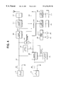
- FIG. 4 is a block diagram showing the detailed circuit configuration of a mobile telephone apparatus according to the second embodiment.
- a battery charger 10 can be electrically connected to a mobile telephone apparatus 20 through a connector 101 .
- the mobile telephone apparatus 20 is provided with communication circuits and other necessary circuits which are not shown for simplicity in this figure.
- the charging power is supplied from the battery charger 10 to a rechargeable battery 102 provided within the mobile telephone apparatus 20 .
- a charge indicator of the mobile telephone apparatus 20 is comprised of a charge detector 103 , an LED controller 104 and an LED 105 .
- the rechargeable battery 102 may be a rechargeable lithium-ion battery.
- the battery charger 10 is designed to charge the lithium-ion battery as well known.
- the charge detector 103 detects the charge state by monitoring a voltage change of a charge power line connecting the connector 101 to the rechargeable battery 102 . More specifically, when the battery charger 10 is connected to the connector 101 of the mobile telephone apparatus 20 , the charge power line increases in voltage. Such a change in voltage is used to detect the connection and the charge state of the battery charger 10 . On the other hand, when the charge detector 103 also detects a predetermined voltage on the charge power line, it is determined that the rechargeable battery 102 is in full charge state. The charge detector 103 outputs a detection signal S DET to the LED controller 104 which controls the LED 105 .
- the LED 105 is provided on the housing of the mobile telephone apparatus 20 so as to be easily visible.
- the LED 105 is normally used to indicate call incoming in an ordinary mobile telephone apparatus.
- the LED 105 is also used to indicate the charge state of the rechargeable battery 102 . More specifically, when the charge detector 103 detects the charge state, the LED controller 104 makes the LED 105 blink or simply light up so as to indicate the charge state.
- the LED 105 lights up in a different way from when normal. It is further desirable that the LED 105 lights up when charging in a different way from when in full charge.
- this embodiment may be implemented by only adding the charge detector 103 and modifying the LED controller 104 such that it makes the LED 105 blink or simply light up so as to indicate not only the call incoming but also the charge state.
- FIG. 2 shows a second embodiment of the present invention, where circuit blocks similar to those previously described with reference to FIG. 1 are denoted by the same reference numerals.
- a battery charger 10 can be electrically connected to a mobile telephone apparatus 30 through a connector 101 . Further, an AC adapter 40 can be electrically connected to the mobile telephone apparatus 30 through a connector 201 .
- the mobile telephone apparatus 20 is provided with communication circuits and other necessary circuits which are not shown for simplicity in this figure.
- the connector 201 is connected to a charge controller 202 and an AC adapter detector 203 .
- the charge controller 202 is further connected to a charge power line which connects the connector 101 to a rechargeable battery 102 .
- the charging power is supplied from one of the battery charger 10 and the AC adapter 40 to the rechargeable battery 102 .
- the rechargeable battery 102 may be a rechargeable lithium-ion battery.
- the battery charger 10 and the charge controller 202 are designed to charge the lithium-ion battery as well known.
- a charge detector 103 detects the charge state by monitoring a voltage change of the charge power line connecting the connector 101 to the rechargeable battery 102 . More specifically, when the battery charger 10 is connected to the connector 101 of the mobile telephone apparatus 30 , the charge power line increases in voltage. Such a change in voltage is used to detect the connection and the charge state of the battery charger 10 . On the other hand, when the charge detector 103 also detects a predetermined voltage on the charge power line, it is determined that the rechargeable battery 102 is in full charge state. The charge detector 103 outputs a detection signal S DET1 to an LED controller 204 and the charge controller 202 .
- the charge controller 202 performs constant current charging of the rechargeable battery 102 when the charge is started by the AC adapter 40 . More specifically, when the AC adapter 40 is connected to the connector 201 of the mobile telephone apparatus 30 , the connector 201 increases in voltage.
- the AC adapter detector 203 monitors such a change in voltage which is used to detect the connection and the charge state of the AC adapter 40 . When detecting the AC adapter 40 , the AC adapter detector 203 outputs a detection signal S DET2 to the LED controller 204 and the charge controller 202 .
- the charge controller 202 starts constant current charging while monitoring the detection signal S DET1 received from the charge detector 103 .
- the charge detector 103 determines that the rechargeable battery 102 is in full charge state and outputs the detection signal S DET1 indicating the full charge state to the charge controller 202 .
- the charge controller 202 changes from the constant current mode to constant voltage mode. Such a charging way is commonly used in the case of lithium-ion battery and it is the same with the battery charger 10 .
- the charge controller 202 further performs selection of charge sources. More specifically, when the battery charger 10 and the AC adapter 40 are both connected to the connectors 101 and 201 , respectively, the charge controller 202 receives both the detection signals S DET1 and S DET2 from the charge detector 103 and the AC adapter detector 203 , respectively. In this case, the charge controller 202 stops the charging operation of the AC adapter 40 (see FIG. 3 ).
- the LED 105 is provided on the housing of the mobile telephone apparatus 30 so as to be easily visible.
- the LED 105 is normally used to indicate call incoming in an ordinary mobile telephone apparatus.
- the LED 105 is also used to indicate the charger type and the charge state of the rechargeable battery 102 .
- the LED controller 204 performs the control of the LED 105 depending on the detection signals S DET1 and S DET2 as in the case of the charge controller 202 . The details of LED control will be described hereinafter with reference to FIG. 3 .
- the LED controller 204 performs normal control of the LED 105 . That is, when an incoming call occurs, the LED 105 blinks or lights up to inform the user of call incoming.
- the LED controller 204 makes the LED 105 operate in a charge operation mode different from the normal operation mode to inform the user of charging by the battery charger 10 .
- the frequency of blinking or the intensity of light may be different between them.
- the detection signal S DET1 is 0 and the detection signal S DET2 is 1.
- the rechargeable battery 102 is charged by the charge controller 202 receiving the charge power from the AC adapter 40 .
- the detection signal S DET1 goes high when the charge is started. Therefore, the LED controller 204 makes the LED 105 operate in the charge operation mode to inform the user of charging by the AC adapter 40 .
- the LED 105 may blink or light up in different way from the normal operation mode. It is possible that, in the case of the AC adapter 40 , the LED controller 204 makes the LED 105 operate in another charge operation mode different from the charge operation mode.
- the detection signals S DET1 and S DET2 is both 1. Since the rechargeable battery 102 is charged by the battery charger 10 in this case as described before, the LED controller 204 makes the LED 105 operate in the charge operation mode.
- the charge operation mode may be different in blinking frequency or light intensity to the normal mode.
- the LED 105 is not limited to a single LED.
- the LED 105 may include a plurality of LEDs so that the normal operation mode and the charge operation mode are indicated by changing lighted-up LED or the frequency of blinking. Further, the different charge operation modes may be indicated by different LEDs or different frequencies of blinking.
- the charge controller 202 and the charge power line can be easily designed to charge the rechargeable battery 102 by the AC adapter 40 .
- the LED controller 204 makes the LED 105 operate in the charge operation mode.
- the LED 105 desirably lights up in a different way from when in full charge.
- FIG. 4 shows the detail circuit configuration of the mobile telephone apparatus 30 of FIG. 2, where circuit blocks similar to those previously described with reference to FIG. 2 are denoted by the same reference numerals and the descriptions are omitted.
- a charge power line 301 connects the connector 101 and the charge controller 202 to the rechargeable battery 102 (here, rechargeable lithium-ion battery).
- the rechargeable battery 102 is further connected to a power controller 302 which controls power supplying to circuits of the mobile telephone apparatus 30 .
- the mobile telephone apparatus 30 is further provided with a microprocessor 303 which performs the control of operations including the LED operations as described before.
- the microprocessor 303 is connected to a speech encoder/decoder (codec) 304 which is further connected to a speaker 305 and a microphone 306 .
- codec speech encoder/decoder
- the microprocessor 303 controls an LED controller 307 so that an LED section 308 is made operate in a selected operation mode as described before.
- the microprocessor 303 controls an LCD controller 309 which controls a liquid-crystal display (LCD) 310 .
- the microprocessor 303 controls a telephone channel controller 311 and a radio system 312 which are used to perform telephone communication.
- the charge controller 202 operate depending on the detection signals S DET1 and S DET2 .
- the microprocessor 303 controls the operations of the LED section 308 depending on the detection signals S DET1 and S DET2 . It is possible that the LED controller 307 controls the operations of the LED section 308 as in the case of FIG. 2 . It is further possible that the microprocessor 303 controls the selection operation of the charge controller 202 and the operations of the LED section 308 .
Abstract
Description
Claims (23)
Applications Claiming Priority (2)
| Application Number | Priority Date | Filing Date | Title |
|---|---|---|---|
| JP9148217A JPH10341273A (en) | 1997-06-05 | 1997-06-05 | Charging display device for portable telephone set |
| JP9-148217 | 1997-06-05 |
Publications (1)
| Publication Number | Publication Date |
|---|---|
| US6526293B1 true US6526293B1 (en) | 2003-02-25 |
Family
ID=15447903
Family Applications (1)
| Application Number | Title | Priority Date | Filing Date |
|---|---|---|---|
| US09/092,010 Expired - Lifetime US6526293B1 (en) | 1997-06-05 | 1998-06-04 | Wireless communication apparatus having rechargeable battery |
Country Status (4)
| Country | Link |
|---|---|
| US (1) | US6526293B1 (en) |
| JP (1) | JPH10341273A (en) |
| AU (1) | AU745700B2 (en) |
| GB (1) | GB2326064B (en) |
Cited By (62)
| Publication number | Priority date | Publication date | Assignee | Title |
|---|---|---|---|---|
| US20020097323A1 (en) * | 2001-01-19 | 2002-07-25 | Takeyoshi Ito | Digital camera |
| US20020107042A1 (en) * | 2001-02-08 | 2002-08-08 | Murnaghan Matthew J. | Handheld wireless communication device |
| US20030162574A1 (en) * | 2002-02-26 | 2003-08-28 | Jia-Hua Fan | Mobile phone charger charged by battery |
| US6709784B2 (en) | 2000-12-22 | 2004-03-23 | Jumpit As | Back-up battery for a cellular telephone |
| US6738649B2 (en) * | 1999-12-08 | 2004-05-18 | Nec Corporation | Portable terminal equipment and method of controlling backlight display therein |
| US20040097275A1 (en) * | 2002-11-20 | 2004-05-20 | Uniden Corporation | Cordless telephone |
| US20040147293A1 (en) * | 2003-01-16 | 2004-07-29 | Samsung Electronics Co., Ltd. | Mobile phone charger with sterilization function and method for sterilizing mobile phone using the same |
| US20060116175A1 (en) * | 2004-11-29 | 2006-06-01 | Cisco Technology, Inc. | Handheld communications device with automatic alert mode selection |
| US20060245611A1 (en) * | 2003-06-04 | 2006-11-02 | Oticon A/S | Hearing aid with visual indicator |
| US20070036298A1 (en) * | 2005-08-03 | 2007-02-15 | Cisco Technology, Inc. | System and method for ensuring call privacy in a shared telephone environment |
| US20070047726A1 (en) * | 2005-08-25 | 2007-03-01 | Cisco Technology, Inc. | System and method for providing contextual information to a called party |
| US20070083918A1 (en) * | 2005-10-11 | 2007-04-12 | Cisco Technology, Inc. | Validation of call-out services transmitted over a public switched telephone network |
| US20070133776A1 (en) * | 2005-12-13 | 2007-06-14 | Cisco Technology, Inc. | Communication system with configurable shared line privacy feature |
| US20070178912A1 (en) * | 2000-03-14 | 2007-08-02 | Robert Baranowski | System and method for enhancing user experience in a wide-area facility having a distributed, bounded environment |
| US20070206738A1 (en) * | 2006-03-02 | 2007-09-06 | Cisco Technology, Inc. | Secure voice communication channel for confidential messaging |
| US20070214041A1 (en) * | 2006-03-10 | 2007-09-13 | Cisco Technologies, Inc. | System and method for location-based mapping of soft-keys on a mobile communication device |
| US20070214040A1 (en) * | 2006-03-10 | 2007-09-13 | Cisco Technology, Inc. | Method for prompting responses to advertisements |
| US20070280456A1 (en) * | 2006-05-31 | 2007-12-06 | Cisco Technology, Inc. | Randomized digit prompting for an interactive voice response system |
| US20070281723A1 (en) * | 2006-05-31 | 2007-12-06 | Cisco Technology, Inc. | Floor control templates for use in push-to-talk applications |
| US20080043968A1 (en) * | 2006-08-02 | 2008-02-21 | Cisco Technology, Inc. | Forwarding one or more preferences during call forwarding |
| US20080175228A1 (en) * | 2007-01-24 | 2008-07-24 | Cisco Technology, Inc. | Proactive quality assessment of voice over IP calls systems |
| US20080233924A1 (en) * | 2007-03-22 | 2008-09-25 | Cisco Technology, Inc. | Pushing a number obtained from a directory service into a stored list on a phone |
| US20090009588A1 (en) * | 2007-07-02 | 2009-01-08 | Cisco Technology, Inc. | Recognition of human gestures by a mobile phone |
| US7477922B2 (en) * | 2000-08-31 | 2009-01-13 | We Thought Of It 1St Limited | Hands-free kit for mobile radio-telephone handset |
| US20090027012A1 (en) * | 2007-07-25 | 2009-01-29 | Sony Corporation | Battery charger |
| US7486648B1 (en) * | 1999-10-11 | 2009-02-03 | Park Tours, Inc. | Wireless extension of local area networks |
| CN100461582C (en) * | 2003-10-27 | 2009-02-11 | 索尼株式会社 | Battery pack |
| US20090098913A1 (en) * | 2000-08-31 | 2009-04-16 | We Though Of It 1St Limited | Hands-Free Kit for Mobile Radio-Telephone Handset |
| US20090128346A1 (en) * | 2007-11-20 | 2009-05-21 | Motorola, Inc. | Alert devices and methods for portable electronic device removal from chargers |
| US20090167542A1 (en) * | 2007-12-28 | 2009-07-02 | Michael Culbert | Personal media device input and output control based on associated conditions |
| US20090170532A1 (en) * | 2007-12-28 | 2009-07-02 | Apple Inc. | Event-based modes for electronic devices |
| EP2115848A1 (en) * | 2007-02-14 | 2009-11-11 | Medical Intelligence Technologies Inc. | System and method for recharging a mobile submersible device |
| US20100123591A1 (en) * | 2008-11-18 | 2010-05-20 | Rosemount Inc. | Universal process transmitter connector |
| US20100163521A1 (en) * | 2008-12-30 | 2010-07-01 | Hitachi Global Storage Technologies Netherlands Bv | System, method and apparatus for fabricating a c-aperture or e-antenna plasmonic near field source for thermal assisted recording applications |
| US7778664B1 (en) | 2001-10-18 | 2010-08-17 | Iwao Fujisaki | Communication device |
| US7853295B1 (en) | 2001-10-18 | 2010-12-14 | Iwao Fujisaki | Communication device |
| US7856248B1 (en) | 2003-09-26 | 2010-12-21 | Iwao Fujisaki | Communication device |
| US7865216B1 (en) | 2001-10-18 | 2011-01-04 | Iwao Fujisaki | Communication device |
| US20110015940A1 (en) * | 2009-07-20 | 2011-01-20 | Nathan Goldfein | Electronic physician order sheet |
| US7890089B1 (en) | 2007-05-03 | 2011-02-15 | Iwao Fujisaki | Communication device |
| US7917167B1 (en) | 2003-11-22 | 2011-03-29 | Iwao Fujisaki | Communication device |
| US20110225073A1 (en) * | 2010-03-12 | 2011-09-15 | Samsung Electronics Co., Ltd. | Apparatus and method for performing wireless charging |
| US8041348B1 (en) | 2004-03-23 | 2011-10-18 | Iwao Fujisaki | Communication device |
| US8229512B1 (en) | 2003-02-08 | 2012-07-24 | Iwao Fujisaki | Communication device |
| US8241128B1 (en) | 2003-04-03 | 2012-08-14 | Iwao Fujisaki | Communication device |
| US8340726B1 (en) | 2008-06-30 | 2012-12-25 | Iwao Fujisaki | Communication device |
| US8433364B1 (en) | 2005-04-08 | 2013-04-30 | Iwao Fujisaki | Communication device |
| US8452307B1 (en) | 2008-07-02 | 2013-05-28 | Iwao Fujisaki | Communication device |
| US8472935B1 (en) | 2007-10-29 | 2013-06-25 | Iwao Fujisaki | Communication device |
| US8543157B1 (en) | 2008-05-09 | 2013-09-24 | Iwao Fujisaki | Communication device which notifies its pin-point location or geographic area in accordance with user selection |
| US8639214B1 (en) | 2007-10-26 | 2014-01-28 | Iwao Fujisaki | Communication device |
| US8676273B1 (en) | 2007-08-24 | 2014-03-18 | Iwao Fujisaki | Communication device |
| US8687785B2 (en) | 2006-11-16 | 2014-04-01 | Cisco Technology, Inc. | Authorization to place calls by remote users |
| US8825090B1 (en) | 2007-05-03 | 2014-09-02 | Iwao Fujisaki | Communication device |
| US9139089B1 (en) | 2007-12-27 | 2015-09-22 | Iwao Fujisaki | Inter-vehicle middle point maintaining implementer |
| US9620987B2 (en) | 2012-04-26 | 2017-04-11 | Eagle Harbor Holdings, Llc | System and method for a dynamically configurable power distribution control and management system |
| US20170348444A1 (en) * | 2014-12-24 | 2017-12-07 | Daekyu JANG | Sterilizer for portable electronic device |
| US20180069425A1 (en) * | 2016-09-07 | 2018-03-08 | Thunder Power New Energy Vehicle Development Company Limited | Electric vehicle system |
| CN110943520A (en) * | 2018-09-21 | 2020-03-31 | 南京翊宁智能科技有限公司 | Charging path management circuit of equipment and equipment |
| US10892088B1 (en) | 2020-02-13 | 2021-01-12 | Texas Institute Of Science, Inc. | Stationary device for contactless electrical energy transmission |
| US11146084B2 (en) * | 2016-09-02 | 2021-10-12 | Superior Communications, Inc. | Car charger with cable and LED activated when devices are connected to connectors |
| US11223222B2 (en) | 2019-09-13 | 2022-01-11 | Texas Institute Of Science, Inc. | Contactless charging apparatus and method for contactless charging |
Families Citing this family (5)
| Publication number | Priority date | Publication date | Assignee | Title |
|---|---|---|---|---|
| JPH11299114A (en) * | 1998-04-16 | 1999-10-29 | Nec Shizuoka Ltd | Mobile telephone |
| EP1844601A4 (en) * | 2005-01-14 | 2009-07-15 | Andrei Leonidovich Vorobiev | Intellectual universal battery charging device for mobile phones |
| JP4702185B2 (en) * | 2006-05-30 | 2011-06-15 | 船井電機株式会社 | Remote control system |
| TW201527945A (en) * | 2014-01-06 | 2015-07-16 | Bungbungame Inc | Electronic device with a power notification function |
| US10523023B2 (en) * | 2016-07-21 | 2019-12-31 | Qualcomm Incorporated | Charger-device pairing for recharge warnings |
Citations (28)
| Publication number | Priority date | Publication date | Assignee | Title |
|---|---|---|---|---|
| US4726052A (en) | 1985-10-03 | 1988-02-16 | Nippon Telegraph & Telephone Corp. | Radio telephone system and method for controlling same |
| US4910103A (en) | 1987-12-10 | 1990-03-20 | Nippon Molicel Corp. | Battery pack for a portable radiotelegraphic unit |
| EP0394074A2 (en) | 1989-04-21 | 1990-10-24 | Motorola, Inc. | Method and apparatus for determining battery type and modifying operating characteristics |
| JPH03215135A (en) | 1990-01-19 | 1991-09-20 | Hitachi Ltd | Rechargeable electronic device |
| US5136229A (en) | 1991-07-15 | 1992-08-04 | Galvin Jay M | Power pack device |
| JPH04315346A (en) | 1991-04-15 | 1992-11-06 | Matsushita Electric Ind Co Ltd | Cordless telephone set |
| JPH0576138A (en) | 1991-06-21 | 1993-03-26 | Mitsubishi Electric Corp | Conduction controller |
| US5223780A (en) * | 1992-07-14 | 1993-06-29 | Stephen Hu | Mobile telephone battery power supply unit with power detection and discharge circuit |
| JPH0750878A (en) | 1994-08-02 | 1995-02-21 | Sanyo Electric Co Ltd | Cordless telephone equipment with automatic answering telephone function |
| GB2288290A (en) | 1994-03-29 | 1995-10-11 | Chiang Chih Cheng | Solar battery charger for mobile telephones |
| JPH0879828A (en) | 1994-09-05 | 1996-03-22 | Hitachi Denshi Ltd | Display method for battery voltage |
| EP0720305A2 (en) | 1994-12-27 | 1996-07-03 | Nec Corporation | Portable telephone set |
| JPH08340295A (en) | 1995-06-14 | 1996-12-24 | Sharp Corp | Cordless telephone set |
| US5677944A (en) | 1993-12-22 | 1997-10-14 | Matsushita Electric Industrial Co., Ltd. | Cordless telephone with battery measuring section |
| JPH1032622A (en) | 1996-07-15 | 1998-02-03 | Saitama Nippon Denki Kk | Charging display system for telephone set |
| US5760754A (en) * | 1995-12-04 | 1998-06-02 | Motorola, Inc. | Light pipe assembly and electrical device using same |
| US5771471A (en) | 1993-06-30 | 1998-06-23 | Motorola, Inc. | Charge regulator for a radio telephone |
| US5870615A (en) * | 1995-01-09 | 1999-02-09 | Intel Corporation | Automatic cellular phone battery charging by mobile personal computer using configuration write data and storage element for charging in accordance to battery charging parameter |
| US5870683A (en) * | 1996-09-18 | 1999-02-09 | Nokia Mobile Phones Limited | Mobile station having method and apparatus for displaying user-selectable animation sequence |
| US5872444A (en) | 1996-04-05 | 1999-02-16 | Sony Corporation | Battery charging device method for charging battery pack and battery pack |
| US5901361A (en) | 1996-12-11 | 1999-05-04 | Telefonaktiebolaget L M Ericsson Publ | Mobile communications apparatus uplink message transmission of battery output level information |
| US6149725A (en) * | 1998-03-09 | 2000-11-21 | Sika Ag, Vorm. Kaspar Winkler & Co. | Injection cement comprising corrosion inhibitors |
| US6157316A (en) | 1995-08-08 | 2000-12-05 | Kokusai Electric Co., Ltd. | Selective call receiver with rechargeable battery |
| US6212403B1 (en) * | 1997-07-03 | 2001-04-03 | Sharp Kabushiki Kaisha | Wireless telephone battery charging while performing data communications |
| US6226533B1 (en) * | 1996-02-29 | 2001-05-01 | Sony Corporation | Voice messaging transceiver message duration indicator and method |
| US6226536B1 (en) * | 1997-05-08 | 2001-05-01 | Nec Corporation | Charger capable of controlling alerting means and radio equipment consisting of the charger and a portable radio apparatus |
| US6311080B1 (en) * | 1998-01-29 | 2001-10-30 | Oki Electric Industry Co., Ltd. | Method for detecting full charge state of battery |
| US6314270B1 (en) * | 1997-05-23 | 2001-11-06 | Matsushita Electric Industrial, Co., Ltd. | Fixed subscriber unit |
Family Cites Families (3)
| Publication number | Priority date | Publication date | Assignee | Title |
|---|---|---|---|---|
| KR920005515A (en) * | 1990-08-09 | 1992-03-28 | 정용문 | Wireless calling method of cordless walkie talkie |
| US5423083A (en) * | 1994-02-14 | 1995-06-06 | Stellmach; Robert N. | Selector adaptor for converting a cellular phone to a bag phone |
| US5570025A (en) * | 1994-11-16 | 1996-10-29 | Lauritsen; Dan D. | Annunciator and battery supply measurement system for cellular telephones |
-
1997
- 1997-06-05 JP JP9148217A patent/JPH10341273A/en active Pending
-
1998
- 1998-06-04 US US09/092,010 patent/US6526293B1/en not_active Expired - Lifetime
- 1998-06-05 AU AU69953/98A patent/AU745700B2/en not_active Ceased
- 1998-06-05 GB GB9812172A patent/GB2326064B/en not_active Expired - Lifetime
Patent Citations (31)
| Publication number | Priority date | Publication date | Assignee | Title |
|---|---|---|---|---|
| US4726052A (en) | 1985-10-03 | 1988-02-16 | Nippon Telegraph & Telephone Corp. | Radio telephone system and method for controlling same |
| US4910103A (en) | 1987-12-10 | 1990-03-20 | Nippon Molicel Corp. | Battery pack for a portable radiotelegraphic unit |
| EP0394074A2 (en) | 1989-04-21 | 1990-10-24 | Motorola, Inc. | Method and apparatus for determining battery type and modifying operating characteristics |
| US5164652A (en) | 1989-04-21 | 1992-11-17 | Motorola, Inc. | Method and apparatus for determining battery type and modifying operating characteristics |
| JPH03215135A (en) | 1990-01-19 | 1991-09-20 | Hitachi Ltd | Rechargeable electronic device |
| JPH04315346A (en) | 1991-04-15 | 1992-11-06 | Matsushita Electric Ind Co Ltd | Cordless telephone set |
| JPH0576138A (en) | 1991-06-21 | 1993-03-26 | Mitsubishi Electric Corp | Conduction controller |
| US5136229A (en) | 1991-07-15 | 1992-08-04 | Galvin Jay M | Power pack device |
| US5223780A (en) * | 1992-07-14 | 1993-06-29 | Stephen Hu | Mobile telephone battery power supply unit with power detection and discharge circuit |
| US5771471A (en) | 1993-06-30 | 1998-06-23 | Motorola, Inc. | Charge regulator for a radio telephone |
| US5677944A (en) | 1993-12-22 | 1997-10-14 | Matsushita Electric Industrial Co., Ltd. | Cordless telephone with battery measuring section |
| GB2288290A (en) | 1994-03-29 | 1995-10-11 | Chiang Chih Cheng | Solar battery charger for mobile telephones |
| JPH0750878A (en) | 1994-08-02 | 1995-02-21 | Sanyo Electric Co Ltd | Cordless telephone equipment with automatic answering telephone function |
| JPH0879828A (en) | 1994-09-05 | 1996-03-22 | Hitachi Denshi Ltd | Display method for battery voltage |
| EP0720305A2 (en) | 1994-12-27 | 1996-07-03 | Nec Corporation | Portable telephone set |
| JPH08186623A (en) | 1994-12-27 | 1996-07-16 | Nec Corp | Portable telephone set with automatic power control function |
| US5867797A (en) | 1994-12-27 | 1999-02-02 | Nec Corporation | Portable telephone set having a power controller causing a current charging of a battery to be held constant |
| US5870615A (en) * | 1995-01-09 | 1999-02-09 | Intel Corporation | Automatic cellular phone battery charging by mobile personal computer using configuration write data and storage element for charging in accordance to battery charging parameter |
| JPH08340295A (en) | 1995-06-14 | 1996-12-24 | Sharp Corp | Cordless telephone set |
| US6157316A (en) | 1995-08-08 | 2000-12-05 | Kokusai Electric Co., Ltd. | Selective call receiver with rechargeable battery |
| US5760754A (en) * | 1995-12-04 | 1998-06-02 | Motorola, Inc. | Light pipe assembly and electrical device using same |
| US6226533B1 (en) * | 1996-02-29 | 2001-05-01 | Sony Corporation | Voice messaging transceiver message duration indicator and method |
| US5872444A (en) | 1996-04-05 | 1999-02-16 | Sony Corporation | Battery charging device method for charging battery pack and battery pack |
| JPH1032622A (en) | 1996-07-15 | 1998-02-03 | Saitama Nippon Denki Kk | Charging display system for telephone set |
| US5870683A (en) * | 1996-09-18 | 1999-02-09 | Nokia Mobile Phones Limited | Mobile station having method and apparatus for displaying user-selectable animation sequence |
| US5901361A (en) | 1996-12-11 | 1999-05-04 | Telefonaktiebolaget L M Ericsson Publ | Mobile communications apparatus uplink message transmission of battery output level information |
| US6226536B1 (en) * | 1997-05-08 | 2001-05-01 | Nec Corporation | Charger capable of controlling alerting means and radio equipment consisting of the charger and a portable radio apparatus |
| US6314270B1 (en) * | 1997-05-23 | 2001-11-06 | Matsushita Electric Industrial, Co., Ltd. | Fixed subscriber unit |
| US6212403B1 (en) * | 1997-07-03 | 2001-04-03 | Sharp Kabushiki Kaisha | Wireless telephone battery charging while performing data communications |
| US6311080B1 (en) * | 1998-01-29 | 2001-10-30 | Oki Electric Industry Co., Ltd. | Method for detecting full charge state of battery |
| US6149725A (en) * | 1998-03-09 | 2000-11-21 | Sika Ag, Vorm. Kaspar Winkler & Co. | Injection cement comprising corrosion inhibitors |
Non-Patent Citations (3)
| Title |
|---|
| Australian Office Action, dated Jul. 19, 2000. |
| Japansese Office Action dated Mar. 23, 1999, with partial translation. |
| Search and Examination Report, Aug. 20, 1998. |
Cited By (219)
| Publication number | Priority date | Publication date | Assignee | Title |
|---|---|---|---|---|
| US7486648B1 (en) * | 1999-10-11 | 2009-02-03 | Park Tours, Inc. | Wireless extension of local area networks |
| US6738649B2 (en) * | 1999-12-08 | 2004-05-18 | Nec Corporation | Portable terminal equipment and method of controlling backlight display therein |
| US20070178912A1 (en) * | 2000-03-14 | 2007-08-02 | Robert Baranowski | System and method for enhancing user experience in a wide-area facility having a distributed, bounded environment |
| US20090098913A1 (en) * | 2000-08-31 | 2009-04-16 | We Though Of It 1St Limited | Hands-Free Kit for Mobile Radio-Telephone Handset |
| US7477922B2 (en) * | 2000-08-31 | 2009-01-13 | We Thought Of It 1St Limited | Hands-free kit for mobile radio-telephone handset |
| US6709784B2 (en) | 2000-12-22 | 2004-03-23 | Jumpit As | Back-up battery for a cellular telephone |
| US20020097323A1 (en) * | 2001-01-19 | 2002-07-25 | Takeyoshi Ito | Digital camera |
| US20080055419A1 (en) * | 2001-01-19 | 2008-03-06 | Takeyoshi Ito | Digital camera using an indicating device to indicate a plurality of functions |
| US7315323B2 (en) * | 2001-01-19 | 2008-01-01 | Fujifilm Corporation | Digital camera using an indicating device to indicate a plurality of functions |
| US20020107042A1 (en) * | 2001-02-08 | 2002-08-08 | Murnaghan Matthew J. | Handheld wireless communication device |
| US8538485B1 (en) | 2001-10-18 | 2013-09-17 | Iwao Fujisaki | Communication device |
| US9154776B1 (en) | 2001-10-18 | 2015-10-06 | Iwao Fujisaki | Communication device |
| US9883025B1 (en) | 2001-10-18 | 2018-01-30 | Iwao Fujisaki | Communication device |
| US7904109B1 (en) | 2001-10-18 | 2011-03-08 | Iwao Fujisaki | Communication device |
| US10284711B1 (en) | 2001-10-18 | 2019-05-07 | Iwao Fujisaki | Communication device |
| US7945286B1 (en) | 2001-10-18 | 2011-05-17 | Iwao Fujisaki | Communication device |
| US9197741B1 (en) | 2001-10-18 | 2015-11-24 | Iwao Fujisaki | Communication device |
| US7945256B1 (en) | 2001-10-18 | 2011-05-17 | Iwao Fujisaki | Communication device |
| US9026182B1 (en) | 2001-10-18 | 2015-05-05 | Iwao Fujisaki | Communication device |
| US8805442B1 (en) | 2001-10-18 | 2014-08-12 | Iwao Fujisaki | Communication device |
| US10425522B1 (en) | 2001-10-18 | 2019-09-24 | Iwao Fujisaki | Communication device |
| US8750921B1 (en) | 2001-10-18 | 2014-06-10 | Iwao Fujisaki | Communication device |
| US7945287B1 (en) | 2001-10-18 | 2011-05-17 | Iwao Fujisaki | Communication device |
| US8744515B1 (en) | 2001-10-18 | 2014-06-03 | Iwao Fujisaki | Communication device |
| US7949371B1 (en) | 2001-10-18 | 2011-05-24 | Iwao Fujisaki | Communication device |
| US7996037B1 (en) | 2001-10-18 | 2011-08-09 | Iwao Fujisaki | Communication device |
| US8538486B1 (en) | 2001-10-18 | 2013-09-17 | Iwao Fujisaki | Communication device which displays perspective 3D map |
| US7945236B1 (en) | 2001-10-18 | 2011-05-17 | Iwao Fujisaki | Communication device |
| US10805451B1 (en) | 2001-10-18 | 2020-10-13 | Iwao Fujisaki | Communication device |
| US8498672B1 (en) | 2001-10-18 | 2013-07-30 | Iwao Fujisaki | Communication device |
| US9537988B1 (en) | 2001-10-18 | 2017-01-03 | Iwao Fujisaki | Communication device |
| US7907942B1 (en) | 2001-10-18 | 2011-03-15 | Iwao Fujisaki | Communication device |
| US9247383B1 (en) | 2001-10-18 | 2016-01-26 | Iwao Fujisaki | Communication device |
| US9883021B1 (en) | 2001-10-18 | 2018-01-30 | Iwao Fujisaki | Communication device |
| US7865216B1 (en) | 2001-10-18 | 2011-01-04 | Iwao Fujisaki | Communication device |
| US8290482B1 (en) | 2001-10-18 | 2012-10-16 | Iwao Fujisaki | Communication device |
| US7907963B1 (en) | 2001-10-18 | 2011-03-15 | Iwao Fujisaki | Method to display three-dimensional map on communication device |
| US8024009B1 (en) | 2001-10-18 | 2011-09-20 | Iwao Fujisaki | Communication device |
| US8200275B1 (en) | 2001-10-18 | 2012-06-12 | Iwao Fujisaki | System for communication device to display perspective 3D map |
| US8086276B1 (en) | 2001-10-18 | 2011-12-27 | Iwao Fujisaki | Communication device |
| US8068880B1 (en) | 2001-10-18 | 2011-11-29 | Iwao Fujisaki | Communication device |
| US7778664B1 (en) | 2001-10-18 | 2010-08-17 | Iwao Fujisaki | Communication device |
| US8064964B1 (en) | 2001-10-18 | 2011-11-22 | Iwao Fujisaki | Communication device |
| US7853295B1 (en) | 2001-10-18 | 2010-12-14 | Iwao Fujisaki | Communication device |
| US7853297B1 (en) | 2001-10-18 | 2010-12-14 | Iwao Fujisaki | Communication device |
| US20030162574A1 (en) * | 2002-02-26 | 2003-08-28 | Jia-Hua Fan | Mobile phone charger charged by battery |
| US20040097275A1 (en) * | 2002-11-20 | 2004-05-20 | Uniden Corporation | Cordless telephone |
| US7424314B2 (en) * | 2003-01-16 | 2008-09-09 | Samsung Electronics Co., Ltd | Mobile phone charger with sterilization function and method for sterilizing mobile phone using the same |
| US20040147293A1 (en) * | 2003-01-16 | 2004-07-29 | Samsung Electronics Co., Ltd. | Mobile phone charger with sterilization function and method for sterilizing mobile phone using the same |
| US8229512B1 (en) | 2003-02-08 | 2012-07-24 | Iwao Fujisaki | Communication device |
| US8682397B1 (en) | 2003-02-08 | 2014-03-25 | Iwao Fujisaki | Communication device |
| US8425321B1 (en) | 2003-04-03 | 2013-04-23 | Iwao Fujisaki | Video game device |
| US8241128B1 (en) | 2003-04-03 | 2012-08-14 | Iwao Fujisaki | Communication device |
| US8430754B1 (en) | 2003-04-03 | 2013-04-30 | Iwao Fujisaki | Communication device |
| US20060245611A1 (en) * | 2003-06-04 | 2006-11-02 | Oticon A/S | Hearing aid with visual indicator |
| US8346304B1 (en) | 2003-09-26 | 2013-01-01 | Iwao Fujisaki | Communication device |
| US11190632B1 (en) | 2003-09-26 | 2021-11-30 | Iwao Fujisaki | Communication device |
| US7890136B1 (en) | 2003-09-26 | 2011-02-15 | Iwao Fujisaki | Communication device |
| US7996038B1 (en) | 2003-09-26 | 2011-08-09 | Iwao Fujisaki | Communication device |
| US11184470B1 (en) | 2003-09-26 | 2021-11-23 | Iwao Fujisaki | Communication device |
| US8010157B1 (en) | 2003-09-26 | 2011-08-30 | Iwao Fujisaki | Communication device |
| US11184468B1 (en) | 2003-09-26 | 2021-11-23 | Iwao Fujisaki | Communication device |
| US7856248B1 (en) | 2003-09-26 | 2010-12-21 | Iwao Fujisaki | Communication device |
| US11184469B1 (en) | 2003-09-26 | 2021-11-23 | Iwao Fujisaki | Communication device |
| US8041371B1 (en) | 2003-09-26 | 2011-10-18 | Iwao Fujisaki | Communication device |
| US10805443B1 (en) | 2003-09-26 | 2020-10-13 | Iwao Fujisaki | Communication device |
| US8055298B1 (en) | 2003-09-26 | 2011-11-08 | Iwao Fujisaki | Communication device |
| US10805445B1 (en) | 2003-09-26 | 2020-10-13 | Iwao Fujisaki | Communication device |
| US8064954B1 (en) | 2003-09-26 | 2011-11-22 | Iwao Fujisaki | Communication device |
| US10805444B1 (en) | 2003-09-26 | 2020-10-13 | Iwao Fujisaki | Communication device |
| US10805442B1 (en) | 2003-09-26 | 2020-10-13 | Iwao Fujisaki | Communication device |
| US10560561B1 (en) | 2003-09-26 | 2020-02-11 | Iwao Fujisaki | Communication device |
| US8090402B1 (en) | 2003-09-26 | 2012-01-03 | Iwao Fujisaki | Communication device |
| US8095181B1 (en) | 2003-09-26 | 2012-01-10 | Iwao Fujisaki | Communication device |
| US8095182B1 (en) | 2003-09-26 | 2012-01-10 | Iwao Fujisaki | Communication device |
| US8121641B1 (en) | 2003-09-26 | 2012-02-21 | Iwao Fujisaki | Communication device |
| US10547722B1 (en) | 2003-09-26 | 2020-01-28 | Iwao Fujisaki | Communication device |
| US10547724B1 (en) | 2003-09-26 | 2020-01-28 | Iwao Fujisaki | Communication device |
| US8150458B1 (en) | 2003-09-26 | 2012-04-03 | Iwao Fujisaki | Communication device |
| US8160642B1 (en) | 2003-09-26 | 2012-04-17 | Iwao Fujisaki | Communication device |
| US8165630B1 (en) | 2003-09-26 | 2012-04-24 | Iwao Fujisaki | Communication device |
| US10547725B1 (en) | 2003-09-26 | 2020-01-28 | Iwao Fujisaki | Communication device |
| US8195228B1 (en) | 2003-09-26 | 2012-06-05 | Iwao Fujisaki | Communication device |
| US10547721B1 (en) | 2003-09-26 | 2020-01-28 | Iwao Fujisaki | Communication device |
| US10547723B1 (en) | 2003-09-26 | 2020-01-28 | Iwao Fujisaki | Communication device |
| US10237385B1 (en) | 2003-09-26 | 2019-03-19 | Iwao Fujisaki | Communication device |
| US8229504B1 (en) | 2003-09-26 | 2012-07-24 | Iwao Fujisaki | Communication device |
| US8233938B1 (en) | 2003-09-26 | 2012-07-31 | Iwao Fujisaki | Communication device |
| US9596338B1 (en) | 2003-09-26 | 2017-03-14 | Iwao Fujisaki | Communication device |
| US8244300B1 (en) | 2003-09-26 | 2012-08-14 | Iwao Fujisaki | Communication device |
| US9077807B1 (en) | 2003-09-26 | 2015-07-07 | Iwao Fujisaki | Communication device |
| US8260352B1 (en) | 2003-09-26 | 2012-09-04 | Iwao Fujisaki | Communication device |
| US8781526B1 (en) | 2003-09-26 | 2014-07-15 | Iwao Fujisaki | Communication device |
| US8781527B1 (en) | 2003-09-26 | 2014-07-15 | Iwao Fujisaki | Communication device |
| US8774862B1 (en) | 2003-09-26 | 2014-07-08 | Iwao Fujisaki | Communication device |
| US8295880B1 (en) | 2003-09-26 | 2012-10-23 | Iwao Fujisaki | Communication device |
| US8301194B1 (en) | 2003-09-26 | 2012-10-30 | Iwao Fujisaki | Communication device |
| US8712472B1 (en) | 2003-09-26 | 2014-04-29 | Iwao Fujisaki | Communication device |
| US8311578B1 (en) | 2003-09-26 | 2012-11-13 | Iwao Fujisaki | Communication device |
| US8320958B1 (en) | 2003-09-26 | 2012-11-27 | Iwao Fujisaki | Communication device |
| US8326355B1 (en) | 2003-09-26 | 2012-12-04 | Iwao Fujisaki | Communication device |
| US8326357B1 (en) | 2003-09-26 | 2012-12-04 | Iwao Fujisaki | Communication device |
| US8331983B1 (en) | 2003-09-26 | 2012-12-11 | Iwao Fujisaki | Communication device |
| US8331984B1 (en) | 2003-09-26 | 2012-12-11 | Iwao Fujisaki | Communication device |
| US8335538B1 (en) | 2003-09-26 | 2012-12-18 | Iwao Fujisaki | Communication device |
| US8694052B1 (en) | 2003-09-26 | 2014-04-08 | Iwao Fujisaki | Communication device |
| US8340720B1 (en) | 2003-09-26 | 2012-12-25 | Iwao Fujisaki | Communication device |
| US8532703B1 (en) | 2003-09-26 | 2013-09-10 | Iwao Fujisaki | Communication device |
| US8447354B1 (en) | 2003-09-26 | 2013-05-21 | Iwao Fujisaki | Communication device |
| US8346303B1 (en) | 2003-09-26 | 2013-01-01 | Iwao Fujisaki | Communication device |
| US8351984B1 (en) | 2003-09-26 | 2013-01-08 | Iwao Fujisaki | Communication device |
| US8447353B1 (en) | 2003-09-26 | 2013-05-21 | Iwao Fujisaki | Communication device |
| US8364202B1 (en) | 2003-09-26 | 2013-01-29 | Iwao Fujisaki | Communication device |
| US8364201B1 (en) | 2003-09-26 | 2013-01-29 | Iwao Fujisaki | Communication device |
| US8380248B1 (en) | 2003-09-26 | 2013-02-19 | Iwao Fujisaki | Communication device |
| US8391920B1 (en) | 2003-09-26 | 2013-03-05 | Iwao Fujisaki | Communication device |
| US8442583B1 (en) | 2003-09-26 | 2013-05-14 | Iwao Fujisaki | Communication device |
| US8417288B1 (en) | 2003-09-26 | 2013-04-09 | Iwao Fujisaki | Communication device |
| CN100461582C (en) * | 2003-10-27 | 2009-02-11 | 索尼株式会社 | Battery pack |
| US8565812B1 (en) | 2003-11-22 | 2013-10-22 | Iwao Fujisaki | Communication device |
| US9674347B1 (en) | 2003-11-22 | 2017-06-06 | Iwao Fujisaki | Communication device |
| US9325825B1 (en) | 2003-11-22 | 2016-04-26 | Iwao Fujisaki | Communication device |
| US9554232B1 (en) | 2003-11-22 | 2017-01-24 | Iwao Fujisaki | Communication device |
| US11115524B1 (en) | 2003-11-22 | 2021-09-07 | Iwao Fujisaki | Communication device |
| US8238963B1 (en) | 2003-11-22 | 2012-08-07 | Iwao Fujisaki | Communication device |
| US9094531B1 (en) | 2003-11-22 | 2015-07-28 | Iwao Fujisaki | Communication device |
| US8295876B1 (en) | 2003-11-22 | 2012-10-23 | Iwao Fujisaki | Communication device |
| US9955006B1 (en) | 2003-11-22 | 2018-04-24 | Iwao Fujisaki | Communication device |
| US7917167B1 (en) | 2003-11-22 | 2011-03-29 | Iwao Fujisaki | Communication device |
| US8554269B1 (en) | 2003-11-22 | 2013-10-08 | Iwao Fujisaki | Communication device |
| US8224376B1 (en) | 2003-11-22 | 2012-07-17 | Iwao Fujisaki | Communication device |
| US8121635B1 (en) | 2003-11-22 | 2012-02-21 | Iwao Fujisaki | Communication device |
| US8121587B1 (en) | 2004-03-23 | 2012-02-21 | Iwao Fujisaki | Communication device |
| US8041348B1 (en) | 2004-03-23 | 2011-10-18 | Iwao Fujisaki | Communication device |
| US8081962B1 (en) | 2004-03-23 | 2011-12-20 | Iwao Fujisaki | Communication device |
| US8270964B1 (en) | 2004-03-23 | 2012-09-18 | Iwao Fujisaki | Communication device |
| US8195142B1 (en) | 2004-03-23 | 2012-06-05 | Iwao Fujisaki | Communication device |
| WO2006057770A3 (en) * | 2004-11-29 | 2007-04-12 | Cisco Tech Inc | Handheld communications device with automatic alert mode selection |
| US7469155B2 (en) * | 2004-11-29 | 2008-12-23 | Cisco Technology, Inc. | Handheld communications device with automatic alert mode selection |
| CN101076949B (en) * | 2004-11-29 | 2014-04-09 | 思科技术公司 | Hand-held communication equipment with automatic alarming mode selection |
| US20060116175A1 (en) * | 2004-11-29 | 2006-06-01 | Cisco Technology, Inc. | Handheld communications device with automatic alert mode selection |
| US10244206B1 (en) | 2005-04-08 | 2019-03-26 | Iwao Fujisaki | Communication device |
| US9549150B1 (en) | 2005-04-08 | 2017-01-17 | Iwao Fujisaki | Communication device |
| US9948890B1 (en) | 2005-04-08 | 2018-04-17 | Iwao Fujisaki | Communication device |
| US8433364B1 (en) | 2005-04-08 | 2013-04-30 | Iwao Fujisaki | Communication device |
| US9143723B1 (en) | 2005-04-08 | 2015-09-22 | Iwao Fujisaki | Communication device |
| US20070036298A1 (en) * | 2005-08-03 | 2007-02-15 | Cisco Technology, Inc. | System and method for ensuring call privacy in a shared telephone environment |
| US8428238B2 (en) | 2005-08-03 | 2013-04-23 | Cisco Technology, Inc. | System and method for ensuring call privacy in a shared telephone environment |
| US20070047726A1 (en) * | 2005-08-25 | 2007-03-01 | Cisco Technology, Inc. | System and method for providing contextual information to a called party |
| US20070083918A1 (en) * | 2005-10-11 | 2007-04-12 | Cisco Technology, Inc. | Validation of call-out services transmitted over a public switched telephone network |
| US20070133776A1 (en) * | 2005-12-13 | 2007-06-14 | Cisco Technology, Inc. | Communication system with configurable shared line privacy feature |
| US20070206738A1 (en) * | 2006-03-02 | 2007-09-06 | Cisco Technology, Inc. | Secure voice communication channel for confidential messaging |
| US8503621B2 (en) | 2006-03-02 | 2013-08-06 | Cisco Technology, Inc. | Secure voice communication channel for confidential messaging |
| US20070214041A1 (en) * | 2006-03-10 | 2007-09-13 | Cisco Technologies, Inc. | System and method for location-based mapping of soft-keys on a mobile communication device |
| US20070214040A1 (en) * | 2006-03-10 | 2007-09-13 | Cisco Technology, Inc. | Method for prompting responses to advertisements |
| US20070280456A1 (en) * | 2006-05-31 | 2007-12-06 | Cisco Technology, Inc. | Randomized digit prompting for an interactive voice response system |
| US20070281723A1 (en) * | 2006-05-31 | 2007-12-06 | Cisco Technology, Inc. | Floor control templates for use in push-to-talk applications |
| US8345851B2 (en) | 2006-05-31 | 2013-01-01 | Cisco Technology, Inc. | Randomized digit prompting for an interactive voice response system |
| US7761110B2 (en) | 2006-05-31 | 2010-07-20 | Cisco Technology, Inc. | Floor control templates for use in push-to-talk applications |
| US20080043968A1 (en) * | 2006-08-02 | 2008-02-21 | Cisco Technology, Inc. | Forwarding one or more preferences during call forwarding |
| US8300627B2 (en) | 2006-08-02 | 2012-10-30 | Cisco Technology, Inc. | Forwarding one or more preferences during call forwarding |
| US8687785B2 (en) | 2006-11-16 | 2014-04-01 | Cisco Technology, Inc. | Authorization to place calls by remote users |
| US20080175228A1 (en) * | 2007-01-24 | 2008-07-24 | Cisco Technology, Inc. | Proactive quality assessment of voice over IP calls systems |
| EP2115848A1 (en) * | 2007-02-14 | 2009-11-11 | Medical Intelligence Technologies Inc. | System and method for recharging a mobile submersible device |
| EP2115848A4 (en) * | 2007-02-14 | 2013-01-23 | Rech Et Dev Everon Ca Inc | System and method for recharging a mobile submersible device |
| US20080233924A1 (en) * | 2007-03-22 | 2008-09-25 | Cisco Technology, Inc. | Pushing a number obtained from a directory service into a stored list on a phone |
| US8639224B2 (en) | 2007-03-22 | 2014-01-28 | Cisco Technology, Inc. | Pushing a number obtained from a directory service into a stored list on a phone |
| US9396594B1 (en) | 2007-05-03 | 2016-07-19 | Iwao Fujisaki | Communication device |
| US8825090B1 (en) | 2007-05-03 | 2014-09-02 | Iwao Fujisaki | Communication device |
| US9185657B1 (en) | 2007-05-03 | 2015-11-10 | Iwao Fujisaki | Communication device |
| US7890089B1 (en) | 2007-05-03 | 2011-02-15 | Iwao Fujisaki | Communication device |
| US9092917B1 (en) | 2007-05-03 | 2015-07-28 | Iwao Fujisaki | Communication device |
| US8825026B1 (en) | 2007-05-03 | 2014-09-02 | Iwao Fujisaki | Communication device |
| US20090009588A1 (en) * | 2007-07-02 | 2009-01-08 | Cisco Technology, Inc. | Recognition of human gestures by a mobile phone |
| US8817061B2 (en) | 2007-07-02 | 2014-08-26 | Cisco Technology, Inc. | Recognition of human gestures by a mobile phone |
| TWI392193B (en) * | 2007-07-25 | 2013-04-01 | Sony Corp | Battery charger and charging method |
| US8035347B2 (en) * | 2007-07-25 | 2011-10-11 | Sony Corporation | Battery charger |
| US20090027012A1 (en) * | 2007-07-25 | 2009-01-29 | Sony Corporation | Battery charger |
| US9232369B1 (en) | 2007-08-24 | 2016-01-05 | Iwao Fujisaki | Communication device |
| US10148803B2 (en) | 2007-08-24 | 2018-12-04 | Iwao Fujisaki | Communication device |
| US9596334B1 (en) | 2007-08-24 | 2017-03-14 | Iwao Fujisaki | Communication device |
| US8676273B1 (en) | 2007-08-24 | 2014-03-18 | Iwao Fujisaki | Communication device |
| US8676705B1 (en) | 2007-10-26 | 2014-03-18 | Iwao Fujisaki | Communication device |
| US9082115B1 (en) | 2007-10-26 | 2015-07-14 | Iwao Fujisaki | Communication device |
| US8639214B1 (en) | 2007-10-26 | 2014-01-28 | Iwao Fujisaki | Communication device |
| US9094775B1 (en) | 2007-10-29 | 2015-07-28 | Iwao Fujisaki | Communication device |
| US8755838B1 (en) | 2007-10-29 | 2014-06-17 | Iwao Fujisaki | Communication device |
| US8472935B1 (en) | 2007-10-29 | 2013-06-25 | Iwao Fujisaki | Communication device |
| WO2009067329A1 (en) * | 2007-11-20 | 2009-05-28 | Motorola, Inc. | Alert devices and methods for portable electronic device removal from chargers |
| US20090128346A1 (en) * | 2007-11-20 | 2009-05-21 | Motorola, Inc. | Alert devices and methods for portable electronic device removal from chargers |
| US9139089B1 (en) | 2007-12-27 | 2015-09-22 | Iwao Fujisaki | Inter-vehicle middle point maintaining implementer |
| US8836502B2 (en) | 2007-12-28 | 2014-09-16 | Apple Inc. | Personal media device input and output control based on associated conditions |
| US20090170532A1 (en) * | 2007-12-28 | 2009-07-02 | Apple Inc. | Event-based modes for electronic devices |
| US20090167542A1 (en) * | 2007-12-28 | 2009-07-02 | Michael Culbert | Personal media device input and output control based on associated conditions |
| US8538376B2 (en) | 2007-12-28 | 2013-09-17 | Apple Inc. | Event-based modes for electronic devices |
| US8543157B1 (en) | 2008-05-09 | 2013-09-24 | Iwao Fujisaki | Communication device which notifies its pin-point location or geographic area in accordance with user selection |
| US11112936B1 (en) | 2008-06-30 | 2021-09-07 | Iwao Fujisaki | Communication device |
| US9060246B1 (en) | 2008-06-30 | 2015-06-16 | Iwao Fujisaki | Communication device |
| US10175846B1 (en) | 2008-06-30 | 2019-01-08 | Iwao Fujisaki | Communication device |
| US10503356B1 (en) | 2008-06-30 | 2019-12-10 | Iwao Fujisaki | Communication device |
| US9241060B1 (en) | 2008-06-30 | 2016-01-19 | Iwao Fujisaki | Communication device |
| US8340726B1 (en) | 2008-06-30 | 2012-12-25 | Iwao Fujisaki | Communication device |
| US9326267B1 (en) | 2008-07-02 | 2016-04-26 | Iwao Fujisaki | Communication device |
| US9049556B1 (en) | 2008-07-02 | 2015-06-02 | Iwao Fujisaki | Communication device |
| US8452307B1 (en) | 2008-07-02 | 2013-05-28 | Iwao Fujisaki | Communication device |
| US7847703B2 (en) | 2008-11-18 | 2010-12-07 | Rosemount Inc. | Universal process transmitter connector |
| US20100123591A1 (en) * | 2008-11-18 | 2010-05-20 | Rosemount Inc. | Universal process transmitter connector |
| US20100163521A1 (en) * | 2008-12-30 | 2010-07-01 | Hitachi Global Storage Technologies Netherlands Bv | System, method and apparatus for fabricating a c-aperture or e-antenna plasmonic near field source for thermal assisted recording applications |
| US20110015940A1 (en) * | 2009-07-20 | 2011-01-20 | Nathan Goldfein | Electronic physician order sheet |
| US9190849B2 (en) * | 2010-03-12 | 2015-11-17 | Samsung Electronics Co., Ltd | Apparatus and method for performing wireless charging |
| US20110225073A1 (en) * | 2010-03-12 | 2011-09-15 | Samsung Electronics Co., Ltd. | Apparatus and method for performing wireless charging |
| US9620987B2 (en) | 2012-04-26 | 2017-04-11 | Eagle Harbor Holdings, Llc | System and method for a dynamically configurable power distribution control and management system |
| US20170348444A1 (en) * | 2014-12-24 | 2017-12-07 | Daekyu JANG | Sterilizer for portable electronic device |
| US11146084B2 (en) * | 2016-09-02 | 2021-10-12 | Superior Communications, Inc. | Car charger with cable and LED activated when devices are connected to connectors |
| US20180069425A1 (en) * | 2016-09-07 | 2018-03-08 | Thunder Power New Energy Vehicle Development Company Limited | Electric vehicle system |
| CN110943520A (en) * | 2018-09-21 | 2020-03-31 | 南京翊宁智能科技有限公司 | Charging path management circuit of equipment and equipment |
| CN110943520B (en) * | 2018-09-21 | 2022-03-01 | 南京翊宁智能科技有限公司 | Charging path management circuit of equipment and equipment |
| US11223222B2 (en) | 2019-09-13 | 2022-01-11 | Texas Institute Of Science, Inc. | Contactless charging apparatus and method for contactless charging |
| US10892088B1 (en) | 2020-02-13 | 2021-01-12 | Texas Institute Of Science, Inc. | Stationary device for contactless electrical energy transmission |
Also Published As
| Publication number | Publication date |
|---|---|
| AU745700B2 (en) | 2002-03-28 |
| GB9812172D0 (en) | 1998-08-05 |
| GB2326064B (en) | 2000-04-19 |
| JPH10341273A (en) | 1998-12-22 |
| AU6995398A (en) | 1998-12-10 |
| GB2326064A (en) | 1998-12-09 |
Similar Documents
| Publication | Publication Date | Title |
|---|---|---|
| US6526293B1 (en) | Wireless communication apparatus having rechargeable battery | |
| US20130049675A1 (en) | Output connector equipped battery pack, battery-pack-and-battery-driven-device system, and charging method by using battery pack | |
| JP2003259560A (en) | Charging circuit | |
| JP2005151609A (en) | Portable electronic device | |
| KR20020078235A (en) | Power supply apparatus and method for portable terminal equipment | |
| EP1686780B1 (en) | Battery detection circuit for cordless telephones | |
| US5610497A (en) | Method and apparatus for providing continuous power to a battery powered device during battery transfer | |
| US6172477B1 (en) | Apparatus for charging a battery of a portable terminal | |
| EP1086521B1 (en) | Two-wire multi-rate battery charger | |
| JPH08186623A (en) | Portable telephone set with automatic power control function | |
| KR100721960B1 (en) | Charge apparatus of second battery within electronic equipment utilized one of commercial alternating power source and dc power source of personal computer | |
| AU745646B2 (en) | Wireless communication apparatus having rechargeable battery | |
| JP2545138B2 (en) | Cordless phone | |
| JP2003299355A (en) | Ac adaptor and charger | |
| JP2001069682A (en) | Power unit | |
| KR100386005B1 (en) | A charging system for portable equipment | |
| KR20040026724A (en) | Charging apparatus of mobile terminal | |
| JP3270301B2 (en) | Rechargeable battery charger | |
| KR100440911B1 (en) | Method for displaying a residual power of a battery of a radio communication equipment, including a step of analyzing a response signal of a repeater to a transmitted signal | |
| KR20030046074A (en) | Battery charging system for hand held phone | |
| KR20030025440A (en) | Head set having a blue tooth module recharger using a mobile phone and recharging method thereof | |
| JPH05300663A (en) | Charger for mobile station | |
| JP3138642B2 (en) | Phone charging display system | |
| KR200256232Y1 (en) | Battery remaining capacity indicating device of handy charger for portable phones | |
| KR20010001430U (en) | Apparatus for inner charging in mobile communication terminal |
Legal Events
| Date | Code | Title | Description |
|---|---|---|---|
| AS | Assignment |
Owner name: NEC CORPORATION, JAPAN Free format text: ASSIGNMENT OF ASSIGNORS INTEREST;ASSIGNOR:MATSUO, RYUJI;REEL/FRAME:009374/0298 Effective date: 19980601 |
|
| STCF | Information on status: patent grant |
Free format text: PATENTED CASE |
|
| FPAY | Fee payment |
Year of fee payment: 4 |
|
| FPAY | Fee payment |
Year of fee payment: 8 |
|
| FPAY | Fee payment |
Year of fee payment: 12 |
|
| AS | Assignment |
Owner name: LENOVO INNOVATIONS LIMITED (HONG KONG), HONG KONG Free format text: ASSIGNMENT OF ASSIGNORS INTEREST;ASSIGNOR:NEC CORPORATION;REEL/FRAME:033720/0767 Effective date: 20140618 |