US6519250B1 - Quick connect internet telephone and method therefor - Google Patents
Quick connect internet telephone and method therefor Download PDFInfo
- Publication number
- US6519250B1 US6519250B1 US09/293,106 US29310699A US6519250B1 US 6519250 B1 US6519250 B1 US 6519250B1 US 29310699 A US29310699 A US 29310699A US 6519250 B1 US6519250 B1 US 6519250B1
- Authority
- US
- United States
- Prior art keywords
- telephone
- dsl
- coupled
- accordance
- quick connect
- Prior art date
- Legal status (The legal status is an assumption and is not a legal conclusion. Google has not performed a legal analysis and makes no representation as to the accuracy of the status listed.)
- Expired - Fee Related
Links
Images


Classifications
-
- H—ELECTRICITY
- H04—ELECTRIC COMMUNICATION TECHNIQUE
- H04M—TELEPHONIC COMMUNICATION
- H04M7/00—Arrangements for interconnection between switching centres
- H04M7/0024—Services and arrangements where telephone services are combined with data services
- H04M7/0057—Services where the data services network provides a telephone service in addition or as an alternative, e.g. for backup purposes, to the telephone service provided by the telephone services network
-
- H—ELECTRICITY
- H04—ELECTRIC COMMUNICATION TECHNIQUE
- H04M—TELEPHONIC COMMUNICATION
- H04M1/00—Substation equipment, e.g. for use by subscribers
- H04M1/253—Telephone sets using digital voice transmission
- H04M1/2535—Telephone sets using digital voice transmission adapted for voice communication over an Internet Protocol [IP] network
-
- H—ELECTRICITY
- H04—ELECTRIC COMMUNICATION TECHNIQUE
- H04M—TELEPHONIC COMMUNICATION
- H04M2203/00—Aspects of automatic or semi-automatic exchanges
- H04M2203/20—Aspects of automatic or semi-automatic exchanges related to features of supplementary services
- H04M2203/2066—Call type detection of indication, e.g. voice or fax, mobile of fixed, PSTN or IP
-
- H—ELECTRICITY
- H04—ELECTRIC COMMUNICATION TECHNIQUE
- H04M—TELEPHONIC COMMUNICATION
- H04M7/00—Arrangements for interconnection between switching centres
- H04M7/006—Networks other than PSTN/ISDN providing telephone service, e.g. Voice over Internet Protocol (VoIP), including next generation networks with a packet-switched transport layer
Definitions
- This invention relates to telephony products and methods therefor and, more specifically, to a quick connect internet telephone and method therefor.
- the quick connect internet telephone allows voice communication to other internet telephones via a DSL connection to an internet network.
- This system or method uses a personal computer (PC) to establish communications with a second PC.
- the communication is established using add-on software and hardware to allow the PCs to convey the user's voices via an internet provider (IP) connection.
- IP internet provider
- a lessor known or used method is a PC to POTS call method.
- a user places a modem telephone call to their internet service provider (ISP) with an internet telephone software equipped PC.
- ISP internet service provider
- IT gateway Internet Telephone
- the second ISP/IT gateway is then used to place a phone call using the conventional phone systems to the desired local number.
- An IT gateway must be available in the same local calling area as the called party. Otherwise, the user has to pay toll charges from the IT gateway to the called party.
- the IT gateway typically charges a fee for the time connected which further increases the cost involved with this method.
- a further problem with this method is that the user has to sign up for IT services with an IT gateway for each geographic area the user desires to place a call. This IT gateway sign up typically includes a monthly subscription fee that must be paid regardless of use or non-use.
- Another alternative method is the IT phone call to IT phone call.
- This method is very similar to the previous method except that regular phones are used at both ends of the call.
- a user places a regular telephone call to a first local IT gateway with a regular telephone.
- An internet link is then established from the first IT gateway to a second IT gateway located proximate to the area to which it is desired to place a phone call.
- the second IT gateway is then used by the user to place a phone call using conventional phone systems to the desired local number.
- This method also has several drawbacks.
- An IT gateway must be available at both ends, locally and in the area to which it is desired to call.
- an IT gateway is not available at either end, the user may actually have to pay double toll charges, one toll charge at the originating end and another toll charge at the receiving end. Furthermore, each IT gateway typically charges a fee for the time connected. Finally, the user has to sign up for IT gateway services with every IT gateway service provider for each geographic area in which he desires to place calls. This IT sign up typically includes a monthly subscription fee that must be paid regardless of use or non-use. It can be seen that this last method can be both cumbersome and could actually be quite expensive.
- a quick connect internet telephone station has a Plain Old Telephone Set (POTS) splitter coupled to a public switched telephone network (PSTN) for directing low frequency signals to a first line and DSL signals to a second line.
- POTS Plain Old Telephone Set
- PSTN public switched telephone network
- a DSL line interface is coupled to the POTS splitter for driving and terminating the second line.
- a DSL transmitter is coupled to the DSL line interface.
- a DSL receiver is also coupled to the DSL line interface.
- a Digital Signal Processor (DSP) is coupled to the DSL transmitter and the DSL receiver.
- a telephone interface is coupled to the first line.
- An audio transceiver device is coupled to the telephone interface.
- a CODEC circuit is also coupled to the telephone interface.
- a ring and hook detect/control circuitry is coupled to the DSP.
- an internet telephone system uses a Public Switched Telephone Network (PSTN).
- PSTN Public Switched Telephone Network
- An internet network is coupled to the PSTN.
- At least two telephone stations are part of the system wherein one of the at least two telephone stations is a DSL telephone station which is coupled to the PSTN.
- a method for using a first DSL telephone for a making telephone call comprises the steps of: dialing a desired telephone number from the first DSL telephone via a telephone network; determining the type of telephone set at the desired telephone number; routing the telephone call through an internet network when the first DSL telephone recognizes the telephone set of the desired telephone number is one of an internet telephone or a second DSL telephone; and routing the telephone call through the telephone network when the first DSL telephone recognizes the telephone set of the desired telephone number is a POTS telephone.
- FIG. 1 is a simplified functional block diagram of the internet telephone system of the present invention.
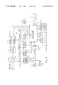
- FIG. 2 is a simplified functional block diagram of the quick connect internet telephone station of the present invention.
- FIG. 3 is a functional block diagram of the firmware module used in the DSP of the quick connect internet telephone station depicted in FIG. 2 .
- High-bit-rate Digital Subscriber Loop (HDSL) and Asymmetrical Digital Subscriber Loop (ADSL) was originally developed to replace T1 carrier and video on demand services, respectively.
- These digital subscriber loops allow a Customer Premise Equipment (CPE) to have a permanent data connection to a Public Switched Telephone Network (PSTN).
- PSTN Public Switched Telephone Network
- ADSL has been developed for making Plain Old Telephone Set (POTS) telephone calls and allowing a higher speed data transmission on the same telephone line simultaneously.
- POTS telephone call utilizes the lowest frequency band (approximately 0 to 4 kHz).
- DMT Discrete Multiple Tone
- the frequency band for DMT application is between 25 kHz and 1.1 MHz.
- up to an 8 Mbits/sec data string could be transmitted downstream by up to 256 separate 4.3125 KhZ tones in the frequency band of 138 kHz to 1.1 MHz.
- Up to 800 Kbits/s of data could be transmitted upstream in 32 tones between 25 kHz and 138 kHz.
- FIG. 1 a simplified block diagram of the operating environment of the quick connect internet telephone system 10 (hereinafter system 10 ) of the present invention is shown.
- the system has at least one ADSL internet telephone 12 .
- the ADSL internet telephone 12 is coupled to a Public Switched Telephone Network (PSTN) 16 via an ADSL line 14 .
- PSTN Public Switched Telephone Network
- a second telephone 18 is also coupled to the PSTN 16 .
- the second telephone may be a second ADSL telephone 18 A, an internet telephone 18 B, or a non-internet telephone 18 C (i.e. Plain Old Telephone Set (POTS)).
- POTS Plain Old Telephone Set
- the second telephone 18 is an ADSL telephone 18 A
- the ADSL telephone 18 A would be coupled to the PSTN by an ADSL line 20 .
- the second telephone 18 is an internet telephone 18 B or a non-internet telephone 18 C
- the second telephone 18 is coupled to the PSTN 16 via lines 22 and 24 respectively.
- ADSL technology will allow an ADSL internet telephone 12 to have a continuous on-line data connection to the PSTN 16 and then to an internet network 26 via an Internet Service Provider (ISP) 28 .
- ISP Internet Service Provider
- all toll charges may be avoided when calling a compatible ADSL internet telephone 18 A or an internet telephone 18 B by establishing a voice communication channel through the internet network 26 via each parties' ISP 28 .
- the call set-up time for the ADSL telephone 12 is usually much shorter than that of a normal DTMF dialing through the PSTN, since a dial-up connection through an analog modem is not required.
- the ADSL internet telephone 12 will preferably have a keypad for entering the name, PSTN number, E-Mail/IP address, telephone type, and other information of frequently called, and/or most recently called individuals. This information is generally saved in the memory of the ADSL internet telephone 12 .
- the ADSL internet telephone 12 When making a telephone call, the ADSL internet telephone 12 will detect a hook switch off hook signal. The user of the ADSL internet telephone 12 will then enter a desired PSTN number. The ADSL internet telephone 12 will search for the PSTN number in the data base. If the PSTN number is not found in the data base of the ADSL internet telephone 12 , the ADSL internet telephone 12 will send an off-hook signal followed by the PSTN number of the called number in DTMF digits to the PSTN 16 . A procedure for information exchange then begins.
- the ADSL internet telephone 12 When the ADSL internet telephone 12 is calling a compatible ADSL internet telephone 18 A or an internet telephone 18 B, the call is automatically answered on the first ring by the corresponding telephone of the called party.
- a direct modem transmission is set up between the calling ADSL internet telephone 12 and the called party's telephone (i.e., compatible ADSL internet telephone 18 A or an internet telephone 18 B).
- Information such as each parties' telephone number, name, telephone type, and IP address is exchanged between the ADSL internet telephone 12 and the called party's telephone (i.e., compatible ADSL internet telephone 18 A or an internet telephone 18 B). This information is then saved in each telephone's data base.
- the ADSL internet telephone 12 sends a START_VOICE_COMMUNICATION protocol and user information to the IP address of the called party via an ADSL link to its ISP 28 .
- the ADSL internet telephone 12 also sends an off-hook signal and number to the PSTN 16 .
- the ADSL internet telephone 12 Upon receipt of READY_VOICE_COMMUNICATION protocol from the called party's ADSL internet telephone 18 A, the ADSL internet telephone 12 sends an off-hook signal to the telephone company to terminate the PSTN call.
- a voice communication through the internet network 26 is established via the ADSL lines and each parties ISP 28 . If a READY_VOICE_COMMUNICATION is not received by the ADSL internet telephone 12 , the ADSL internet telephone 12 waits to establish a POTS telephone call via the PSTN 16 .
- the calling ADSL telephone 12 Upon detection of a hook switch on-hook signal, the calling ADSL telephone 12 will stop sending voice packets.
- the calling ADSL internet telephone 12 will send an END_VOICE_COMMUNICATION protocol to the IP address of the called ADSL internet telephone 18 A.
- the ADSL internet telephone 12 receives a REQUEST_END_VOICE protocol from the called party's ADSL internet telephone 18 A, or after a period of time without reception of voice packets, the ADSL internet telephone 12 will apply background noise to the speaker informing the user that the called party has ended the telephone conversation.
- the ADSL internet telephone 12 will detect only a single ringing tone. The ADSL internet telephone 12 will mute both the voice transmitter and receiver. The ADSL internet telephone 12 will then send its IP address and user information by a direct modem signal to the internet telephone 18 B. If a data packet including the called internet telephone's 18 B IP address and user information is not received, both voice transmitter and receiver of the ADSL internet telephone 12 are unmuted to establish a POTS telephone call via the PSTN 16 . If a data packet including the internet telephone's 18 B IP address and user information is received, the ADSL internet telephone 12 saves the information in its data base. This information may further be displayed.
- the ADSL internet telephone 12 will then go on-hook for a short duration (approximately 2 seconds).
- the ADSL internet telephone 12 will dial the telephone number of its ISP 28 .
- the ADSL internet telephone 12 Upon connection to its ISP 28 , the ADSL internet telephone 12 will send a beginning-of-conversation protocol to the IP address of the internet telephone 18 B.
- the ADSL Internet telephone 12 Upon detection of a hook switch off-hook signal, the ADSL Internet telephone 12 will send packetized voice signals to the IP address of the internet telephone 18 B.
- the ADSL internet telephone 12 Upon receipt of packetized data from the called internet telephone 18 B, the ADSL internet telephone 12 will convert the voice data into analog signals to establish a voice communication path via the internet network 26 .
- the ADSL internet telephone 12 When the ADSL internet telephone 12 detects a hook switch on-hook signal, it stops sending voice packets and sends an end-of-conversation protocol to the IP address of the internet telephone 18 B. When the ADSL internet telephone 12 receives an end-of-conversation protocol from the called party's internet telephone 18 B, or after a period of time without reception of voice packets, the ADSL internet telephone 12 will apply background noise to the speaker informing the user that the called party has ended the telephone conversation.
- the non-internet telephone 18 C will not automatically answered the telephone call at the first ring tone as in the previous two examples above (i.e., compatible ADSL internet telephone 18 A or an internet telephone 18 B).
- the ADSL internet telephone 12 will know to process the call as a regular telephone call through the PSTN 16 .
- the non-internet telephone 18 C will not be able to receive the calling party's user information and reply with its own information.
- the call will be processed as a regular POTS call via the PSTN 16 .
- the ADSL internet telephone 12 is coupled to an ADSL line 30 .
- the ADSL line 30 is a regular external telephone line which has ADSL capabilities.
- a POTS splitter 32 is coupled to the ADSL line 30 .
- the POTS splitter 32 is generally comprised of both a low pass filter 32 A and a high pass filter 32 B.
- the low pass filter 32 A is used to provide the pass band for voice frequency signals, dial tone, ringing, and on/off hook signals.
- the high pass filter 32 B is used for the ADSL signals.
- An ADSL interface 34 is coupled to the POTS splitter 32 .
- the ADSL interface 34 is used to drive and terminate the ADSL line.
- An ADSL receiver 36 is coupled to an output of the ADSL line interface 34 .
- the ADSL receiver first converts the analog signal into a digital signal.
- the digital signal is then passed through a time domain equalizer into serial data.
- the serial data is converted into multiple channels. Data in each channel is converted into frequency domain signals by a Fast Fourier Transform (FFT) algorithm.
- FFT Fast Fourier Transform
- the frequency domain signals pass through a frequency domain equalizer, then to a symbol decision, bit decision, and invert parsing functions.
- the output bit stream from the ADSL receiver 36 is then sent to a Digital Signal Processor (DSP) 38 .
- DSP Digital Signal Processor
- An ADSL transmitter 40 is coupled to both the DSP 38 and the ADSL line interface 34 .
- the ADSL transmitter 40 receives bit streams from the DSP 38 .
- the ADSL transmitter 40 will convert the serial bit stream into parallel data.
- the parallel data is mapped into multibit subchannels according to a bit allocation algorithm.
- Each multibit subchannel data is converted into time domain signals by Inverse Fast Fourier Transform (IFFT).
- IFFT Inverse Fast Fourier Transform
- the parallel time domain signals are then converted into serial signals and then converted into analog signals to be outputted by the ADSL transmitter 40 .
- the ADSL internet telephone 12 will further comprise a Digital-Analog-Analog (DAA) telephone interface 42 , a ring detector 44 , an off-hook detector 46 , a hook switch 48 , and a ringer 50 all of which have input terminals coupled to the ADSL line 30 .
- the DAA telephone interface 42 is used to convert signals from the ADSL line 30 to a four wire interface.
- the DAA telephone interface 42 is further used to send signals from the DSP 38 , which have been converted to analog signals by the CODEC 52 , to the ADSL line 30 .
- the ring detector 44 is a circuit which monitors when an incoming telephone call is made to the ADSL internet telephone 12 .
- the DSP 38 will energize the ringer 50 to signal that a calling is being placed to the ADSL internet telephone 12 .
- the off-hook detector 46 will monitor when the headset of the ADSL internet telephone 12 is lifted thereby allowing dialing and transmission but prohibiting incoming calls from being answered.
- the hook switch 48 is a switch that closes a circuit when the headset of the ADSL internet telephone 12 is lifted thereby allowing dialing and transmission but prohibiting incoming calls from being answered.
- a (Coder/Decoder) CODEC 52 is coupled to the DAA telephone interface 42 .
- the CODEC 52 receives analog signals from the DAA telephone interface 42 .
- the CODEC 52 will convert the analog signals to digital signals and send the digital signals to the DSP 38 for processing.
- a microphone 54 and a speaker 56 may also be coupled to the DAA telephone interface 42 .
- the microphone 54 is used to convert sound waves into electronic signals.
- the speaker 56 will convert electronic impulses to sound waves of sufficient volume to be heard.
- a keypad 56 is coupled to the DSP 38 .
- the keypad 58 is used to enter user information of parties who are frequently called. Such information may include, but is not limited to, a party's name, telephone number, telephone type, and ISP/IP address.
- This information is generally stored in a data base in the ADSL internet telephone 12 .
- the data base is generally a memory module.
- the memory module is comprised of Random Access Memory (RAM) 58 and FLASH memory 60 .
- the FLASH memory 60 is generally used to store firmware programs and information entered by the user via the keypad 56 (i.e., information of parties who are frequently called such as, a party's name, telephone number, telephone type, and ISP/IP address).
- the RAM 58 is generally used as a scratch pad during program execution.
- a display mechanism 54 is also coupled to the DSP 38 .
- the display mechanism 54 is a Liquid Crystal Display (LCD) 54 .
- the LCD 54 is used for displaying information that the user entered via the keypad 56 such as the party's name, telephone number, telephone type, and ISP/IP address.
- the LCD 54 may also function to display information concerning an incoming call.
- the LCD 54 may function like a Caller ID unit.
- firmware features implemented in the DSP 38 is shown. Hardware components for these features are commercially available. Firmware implementation of these features is used as an example.
- the firmware features generally include: a signal selector 62 , packet assembler 64 , DTMF generator 66 , MODEM transmitter 68 , data compressor 70 , packet disassembler 72 , Call Progress (CP) detector, MODEM receiver 76 , and data decompressor 78 .
- the functions of these firmware features of the DSP 38 will be discussed below.
- the internet telephone 18 B is similar in design to that of the ADSL internet telephones 12 and 18 A shown in FIGS. 2 and 3 except that the specific ADSL function blocks are not included. Thus, the operation of the internet telephone 18 B will be described in reference to FIGS. 2 and 3.
- the ADSL internet telephone 12 dials a telephone number by sending Dual Tone Multiple Frequencies (DTMF) to the PSTN 16 .
- DTMF dialing is a traditional hardware function. It is implemented in this embodiment of the ADSL internet telephone 12 as a firmware function.
- the DTMF generator 66 a firmware function of the DSP 38 , sends DTMF signals to the signal selector 62 . This signal is converted into an analog signal by the CODEC 23 and sent to the ADSL line 30 through the DAA telephone interface 42 .
- a telephone company will make a connection to the dialed number via the PSTN 16 and will send a ringing signal to the dialed number.
- the non-internet telephone 18 C will ring continuously till an end user answers the call.
- the ringing detector 44 detects incoming ringing signals and informs the DSP 38 of the incoming ringing signals.
- the DSP 38 Upon receipt of a first ringing signal, the DSP 38 disables the ringer 50 to stop the called party from lifting the headset of the called telephone 18 A.
- the DSP 38 activates the electronic hook switch 48 to close the loop and answer the incoming telephone call.
- incoming signals on the ADSL line 30 are converted to a four wire interface by the DAA telephone interface 42 .
- the incoming signals are digitized by the CODEC 52 and sent to the CP detector 74 , a firmware module within the DSP 38 .
- the called party is a non-internet telephone 18 C. Ringing will continue till the non-internet telephone 18 C is answered by the called party or the calling party discontinues the telephone call.
- the call will be routed through the PSTN 16 . No attempt is made to reroute the call through the internet network 26 .
- the calling ADSL internet telephone 12 detects only a single ringing tone, this call is answered by the called telephone 18 A. An exchange of user information will begin.
- the DSP 38 will send a signal causing the LED 55 to begin to flash indicating that an exchange of user information has begun.
- the ADSL internet telephone 12 will transfer its user information in the following manner.
- the DSP 38 will retrieve the user information (i.e., name, telephone number, telephone type, and ISP/IP address) of the ADSL internet telephone 12 from the FLASH memory 29 .
- the packet assembler 64 assembles the information into data packets which is converted into a MODEM signal in a digitized format by the MODEM transmitter 68 .
- the digitized MODEM signal is sent to the CODEC 52 through the signal selector 62 .
- the CODEC 52 converts the digitized MODEM signal into an analog signal.
- the analog signal is sent to the ADSL line 30 through the DAA telephone interface 42 to the called telephone 18 A.
- the called telephone 18 A receives the MODEM signal in its analog form at its DAA telephone interface 42 .
- the analog signal is converted to a digital signal by the CODEC 52 and is sent to the MODEM receiver 76 via the signal selector 62 .
- the DSP 38 disassembles the data packet from the MODEM receiver 76 , displays the calling party's telephone number and name on the LCD 54 .
- the DSP 38 will also store the calling party's information in its FLASH memory 60 .
- the DSP 38 of both the calling ADSL internet telephone 12 and the called telephone 18 A deactivate their respective electronic hook switch 48 to go on-hook. After approximately two seconds of delay, each DSP 38 activates its respective electronic hook switch 48 to go to an off-hook state.
- the DTMF generator 66 of the calling ADSL internet telephone 12 sends the telephone number of its ISP 28 through the signal selector 62 .
- the digital signal is converted into an analog signal by the CODEC 52 .
- the DTMF signal in analog format is sent to the ADSL line 30 via the DAA telephone interface 42 .
- the PSTN 16 Upon receipt of the DTMF signal, the PSTN 16 connects this call to the ISP 28 .
- the CP detector 74 detects the end of a ringing tone, it informs the MODEM transmitter 68 to begin transmission of a MODEM signal training sequence at a speed of 14.4 kbps.
- the CODEC 52 begins to receive voice signals through the microphone 54 via the DAA telephone interface 42 .
- the CODEC digitizes the voice signal at 8 k bytes per second or 64 kbps.
- the digitized voice signal is sent to the data compressor 70 where the voice signal is compressed using the GSM algorithm to 13 kbps or the ITU G 723.1 algorithm to about 6 kbps.
- the data packet assembler 64 assembles the compressed data with the IP address of the called telephone 18 A.
- the data packet is sent to the MODEM transmitter 68 , to the signal selector 62 , to the CODEC 52 , through the DAA telephone interface 42 , then to the ADSL line 30 .
- the called telephone 18 A calls its ISP 28 and begins transmission of packetized voice signals with the IP address of the calling ADSL internet telephone 12 .
- a voice transmission path is now established via the internet network 26 .
- the ADSL internet telephone 12 receives the MODEM signal from the ADSL line 30 .
- the MODEM signal is sent through the DAA telephone interface 42 , to the CODEC 52 , to the MODEM receiver 76 where the signal is converted to data packets.
- the data packets are sent to the data decompressor 78 where the IP address and other overhead bytes are removed to obtain the compressed data.
- the compressed data is converted into 64 kbps data. This data is converted into an analog signal which is sent to the speaker 56 via the CODEC 52 and the DAA telephone interface 42 .
- a voice reception path is now established through the internet network 26 .
- the call is routed through the internet network 26 .
- Toll charges can now be saved.
Abstract
Description
Claims (50)
Priority Applications (1)
| Application Number | Priority Date | Filing Date | Title |
|---|---|---|---|
| US09/293,106 US6519250B1 (en) | 1999-04-16 | 1999-04-16 | Quick connect internet telephone and method therefor |
Applications Claiming Priority (1)
| Application Number | Priority Date | Filing Date | Title |
|---|---|---|---|
| US09/293,106 US6519250B1 (en) | 1999-04-16 | 1999-04-16 | Quick connect internet telephone and method therefor |
Publications (1)
| Publication Number | Publication Date |
|---|---|
| US6519250B1 true US6519250B1 (en) | 2003-02-11 |
Family
ID=23127687
Family Applications (1)
| Application Number | Title | Priority Date | Filing Date |
|---|---|---|---|
| US09/293,106 Expired - Fee Related US6519250B1 (en) | 1999-04-16 | 1999-04-16 | Quick connect internet telephone and method therefor |
Country Status (1)
| Country | Link |
|---|---|
| US (1) | US6519250B1 (en) |
Cited By (12)
| Publication number | Priority date | Publication date | Assignee | Title |
|---|---|---|---|---|
| US20020196774A1 (en) * | 2001-03-28 | 2002-12-26 | Jeffrey Wissing | Post extender for voice fallback in a subscriber line |
| US20020199003A1 (en) * | 2001-04-13 | 2002-12-26 | Frank Sacca | Modem for internet connection |
| US20030185204A1 (en) * | 2002-04-01 | 2003-10-02 | Murdock Scott D. | Data communication system combining pay telephone and wireless access technologies |
| US6747995B1 (en) * | 1998-09-21 | 2004-06-08 | Lucent Technologies Inc. | System for multiple voice lines with data over a single subscriber loop |
| US20050008033A1 (en) * | 2000-04-18 | 2005-01-13 | Serconet Ltd. | Telephone communication system over a single telephone line |
| US20050036472A1 (en) * | 1998-04-28 | 2005-02-17 | Dan Kikinis | Methods and apparatus for enhancing wireless data network telephony, including quality of service monitoring and control |
| US20050074008A1 (en) * | 2003-09-23 | 2005-04-07 | France Telecom | Method and an associated device for setting up a transfer of data between two communications devices |
| US6940807B1 (en) * | 1999-10-26 | 2005-09-06 | Velocity Communication, Inc. | Method and apparatus for a X-DSL communication processor |
| US7016377B1 (en) * | 1999-10-27 | 2006-03-21 | Samsung Electronics Co., Ltd. | Home network system in asymmetric digital subscriber line system |
| US7023989B1 (en) * | 2001-06-19 | 2006-04-04 | Cisco Technology, Inc. | Arrangement for delivering applications to a network enabled telephony device |
| EP2180680A1 (en) * | 2008-10-25 | 2010-04-28 | Huawei Technologies Co., Ltd. | Separation device and method for transmitting voice signal |
| USRE45149E1 (en) | 1998-04-28 | 2014-09-23 | Genesys Telecommunications Laboratories, Inc. | Methods and apparatus for enhancing wireless data network telephony, including quality of service monitoring and control |
Citations (6)
| Publication number | Priority date | Publication date | Assignee | Title |
|---|---|---|---|---|
| US5751741A (en) * | 1996-11-20 | 1998-05-12 | Motorola, Inc. | Rate-adapted communication system and method for efficient buffer utilization thereof |
| US6075784A (en) * | 1998-06-08 | 2000-06-13 | Jetstream Communications, Inc. | System and method for communicating voice and data over a local packet network |
| US6084873A (en) * | 1997-03-18 | 2000-07-04 | 3Com Corporation | Method for bypassing telephone network |
| US6141356A (en) * | 1997-11-10 | 2000-10-31 | Ameritech Corporation | System and method for distributing voice and data information over wireless and wireline networks |
| US6144695A (en) * | 1997-12-23 | 2000-11-07 | At&T Corp. | Method and apparatus for reducing near-end crosstalk (NEXT) in discrete multi-tone modulator/demodulators |
| US6240073B1 (en) * | 1997-11-14 | 2001-05-29 | Shiron Satellite Communications (1996) Ltd. | Reverse link for a satellite communication network |
-
1999
- 1999-04-16 US US09/293,106 patent/US6519250B1/en not_active Expired - Fee Related
Patent Citations (6)
| Publication number | Priority date | Publication date | Assignee | Title |
|---|---|---|---|---|
| US5751741A (en) * | 1996-11-20 | 1998-05-12 | Motorola, Inc. | Rate-adapted communication system and method for efficient buffer utilization thereof |
| US6084873A (en) * | 1997-03-18 | 2000-07-04 | 3Com Corporation | Method for bypassing telephone network |
| US6141356A (en) * | 1997-11-10 | 2000-10-31 | Ameritech Corporation | System and method for distributing voice and data information over wireless and wireline networks |
| US6240073B1 (en) * | 1997-11-14 | 2001-05-29 | Shiron Satellite Communications (1996) Ltd. | Reverse link for a satellite communication network |
| US6144695A (en) * | 1997-12-23 | 2000-11-07 | At&T Corp. | Method and apparatus for reducing near-end crosstalk (NEXT) in discrete multi-tone modulator/demodulators |
| US6075784A (en) * | 1998-06-08 | 2000-06-13 | Jetstream Communications, Inc. | System and method for communicating voice and data over a local packet network |
Cited By (35)
| Publication number | Priority date | Publication date | Assignee | Title |
|---|---|---|---|---|
| US20050036472A1 (en) * | 1998-04-28 | 2005-02-17 | Dan Kikinis | Methods and apparatus for enhancing wireless data network telephony, including quality of service monitoring and control |
| USRE45597E1 (en) * | 1998-04-28 | 2015-06-30 | Genesys Telecommunications Laboratories, Inc. | Methods and apparatus for enhancing wireless data network telephony, including quality of service monitoring and control |
| USRE45149E1 (en) | 1998-04-28 | 2014-09-23 | Genesys Telecommunications Laboratories, Inc. | Methods and apparatus for enhancing wireless data network telephony, including quality of service monitoring and control |
| US7852830B2 (en) * | 1998-04-28 | 2010-12-14 | Genesys Telecommunications Laboratories, Inc. | Methods and apparatus for enhancing wireless data network telephony, including quality of service monitoring and control |
| US6747995B1 (en) * | 1998-09-21 | 2004-06-08 | Lucent Technologies Inc. | System for multiple voice lines with data over a single subscriber loop |
| US6940807B1 (en) * | 1999-10-26 | 2005-09-06 | Velocity Communication, Inc. | Method and apparatus for a X-DSL communication processor |
| US7016377B1 (en) * | 1999-10-27 | 2006-03-21 | Samsung Electronics Co., Ltd. | Home network system in asymmetric digital subscriber line system |
| US20080043646A1 (en) * | 2000-04-18 | 2008-02-21 | Serconet Ltd. | Telephone communication system over a single telephone line |
| US8000349B2 (en) | 2000-04-18 | 2011-08-16 | Mosaid Technologies Incorporated | Telephone communication system over a single telephone line |
| US20050117603A1 (en) * | 2000-04-18 | 2005-06-02 | Serconet, Ltd. | Telephone communication system over a single telephone line |
| US8559422B2 (en) | 2000-04-18 | 2013-10-15 | Mosaid Technologies Incorporated | Telephone communication system over a single telephone line |
| US8223800B2 (en) | 2000-04-18 | 2012-07-17 | Mosaid Technologies Incorporated | Telephone communication system over a single telephone line |
| US20060182095A1 (en) * | 2000-04-18 | 2006-08-17 | Serconet Ltd. | Telephone communication system over a single telephone line |
| US20060182094A1 (en) * | 2000-04-18 | 2006-08-17 | Serconet Ltd. | Telephone communication system over a single telephone line |
| US7106721B1 (en) * | 2000-04-18 | 2006-09-12 | Serconet, Ltd. | Telephone communication system over a single telephone line |
| US7197028B2 (en) * | 2000-04-18 | 2007-03-27 | Serconet Ltd. | Telephone communication system over a single telephone line |
| US20080232579A1 (en) * | 2000-04-18 | 2008-09-25 | Serconet Ltd. | Telephone communication system over a single telephone line |
| US20050008033A1 (en) * | 2000-04-18 | 2005-01-13 | Serconet Ltd. | Telephone communication system over a single telephone line |
| US20080037523A1 (en) * | 2001-03-28 | 2008-02-14 | Wi-Lan, Inc. | POTS Extender for Voice Fallback in a Subscriber Line |
| US20020196774A1 (en) * | 2001-03-28 | 2002-12-26 | Jeffrey Wissing | Post extender for voice fallback in a subscriber line |
| US7254110B2 (en) * | 2001-03-28 | 2007-08-07 | Wi-Lan, Inc. | Pots extender for voice fallback in a subscriber line |
| US8233472B2 (en) | 2001-03-28 | 2012-07-31 | Wi-Lan, Inc. | POTS extender for voice fallback in a subscriber line |
| US8724482B2 (en) | 2001-03-28 | 2014-05-13 | Wi-Lan, Inc. | POTS extender for voice fallback in a subscriber line |
| US20080019355A1 (en) * | 2001-03-28 | 2008-01-24 | Wi-Lan, Inc. | POTS Extender for Voice Fallback in a Subscriber Line |
| US20020199003A1 (en) * | 2001-04-13 | 2002-12-26 | Frank Sacca | Modem for internet connection |
| US7023989B1 (en) * | 2001-06-19 | 2006-04-04 | Cisco Technology, Inc. | Arrangement for delivering applications to a network enabled telephony device |
| US7327842B2 (en) | 2001-06-19 | 2008-02-05 | Cisco Technology, Inc. | Arrangement for delivering applications to a network enabled telephony device |
| US20060168282A1 (en) * | 2001-06-19 | 2006-07-27 | Turner Bryan C | Arrangement for delivering applications to a network enabled telephony device |
| US20030185204A1 (en) * | 2002-04-01 | 2003-10-02 | Murdock Scott D. | Data communication system combining pay telephone and wireless access technologies |
| US7643470B2 (en) * | 2003-09-23 | 2010-01-05 | France Telecom | Method and an associated device for setting up a transfer of data between two communications devices |
| US20050074008A1 (en) * | 2003-09-23 | 2005-04-07 | France Telecom | Method and an associated device for setting up a transfer of data between two communications devices |
| EP2180680A1 (en) * | 2008-10-25 | 2010-04-28 | Huawei Technologies Co., Ltd. | Separation device and method for transmitting voice signal |
| US20110182286A1 (en) * | 2008-10-25 | 2011-07-28 | Huawei Technologies Co., Ltd. | Separation device and method for transmitting voice signal |
| US8537809B2 (en) | 2008-10-25 | 2013-09-17 | Huawei Technologies Co., Ltd. | Separation device and method for transmitting voice signal |
| EP2180680B1 (en) * | 2008-10-25 | 2013-10-23 | Huawei Technologies Co., Ltd. | Separation device and method for transmitting voice signal |
Similar Documents
| Publication | Publication Date | Title |
|---|---|---|
| US6424647B1 (en) | Method and apparatus for making a phone call connection over an internet connection | |
| US6424648B1 (en) | Method and apparatus for making a phone call connection over an internet connection | |
| US7672438B2 (en) | Providing multiple line functionality using alternative network telephony | |
| US6636506B1 (en) | Internet telephone system and method therefor | |
| US6337898B1 (en) | Method for monitoring voicemail calls using ADSI capable CPE | |
| KR100614910B1 (en) | Method for setting up a voice call and method of indicating that an internet communication has arrived | |
| US7471671B2 (en) | Band signal detection and presentation for IP phone | |
| US20070025343A1 (en) | Internet telephony arrangement and method | |
| US6487197B1 (en) | Method and apparatus for connecting to a packet based communication system | |
| CA2343481C (en) | Method and apparatus for subscriber line to telephone call distribution | |
| US6519250B1 (en) | Quick connect internet telephone and method therefor | |
| US20130242858A1 (en) | Method and apparatus for wideband and super-wideband telephony | |
| US8594078B2 (en) | Method and apparatus for stand-alone voice over internet protocol with POTS telephone support | |
| CA2345879C (en) | Answer detection for ip based telephones using passive detection | |
| US6542498B2 (en) | Signaling system and method to connect idle internet end stations with application in internet telephony | |
| JP4272379B2 (en) | Method and system for providing telephone service and article | |
| US6493445B2 (en) | Providing alerting/call waiting/call holding services to on-line internet users | |
| JP3002667B2 (en) | Call system | |
| CA2345493C (en) | Tone based answer detection for ip based telephones | |
| US20230062629A1 (en) | Wired telephone to volte adapter | |
| CA2430916A1 (en) | Improved caller identification | |
| KR100402677B1 (en) | Analog subscriber interfacing apparatus for providing a calling identity delivery service | |
| US20040228334A1 (en) | Apparatus and method for network telephony | |
| KR20030004263A (en) | Video telephone use both xdsl for video and pstn for sound | |
| GB2342809A (en) | Method for monitoring voicemail calls using ADSI capable CPE |
Legal Events
| Date | Code | Title | Description |
|---|---|---|---|
| AS | Assignment |
Owner name: FAN, YUAN-NENG, ARIZONA Free format text: ASSIGNMENT OF ASSIGNORS INTEREST;ASSIGNOR:FAN, YUAN-NENG;REEL/FRAME:009914/0577 Effective date: 19990414 |
|
| AS | Assignment |
Owner name: FANSTEL SYSTEMS, LLC, ARIZONA Free format text: ASSIGNMENT OF ASSIGNORS INTEREST;ASSIGNOR:FAN, YUAN-NENG;REEL/FRAME:010130/0097 Effective date: 19990416 |
|
| REMI | Maintenance fee reminder mailed | ||
| FPAY | Fee payment |
Year of fee payment: 4 |
|
| SULP | Surcharge for late payment | ||
| REMI | Maintenance fee reminder mailed | ||
| FPAY | Fee payment |
Year of fee payment: 8 |
|
| SULP | Surcharge for late payment |
Year of fee payment: 7 |
|
| REMI | Maintenance fee reminder mailed | ||
| LAPS | Lapse for failure to pay maintenance fees | ||
| STCH | Information on status: patent discontinuation |
Free format text: PATENT EXPIRED DUE TO NONPAYMENT OF MAINTENANCE FEES UNDER 37 CFR 1.362 |
|
| FP | Expired due to failure to pay maintenance fee |
Effective date: 20150211 |