US6518726B1 - Battery charger and charge control system - Google Patents
Battery charger and charge control system Download PDFInfo
- Publication number
- US6518726B1 US6518726B1 US10/051,402 US5140202A US6518726B1 US 6518726 B1 US6518726 B1 US 6518726B1 US 5140202 A US5140202 A US 5140202A US 6518726 B1 US6518726 B1 US 6518726B1
- Authority
- US
- United States
- Prior art keywords
- lithium
- charging
- ion
- circuitry
- ion cell
- Prior art date
- Legal status (The legal status is an assumption and is not a legal conclusion. Google has not performed a legal analysis and makes no representation as to the accuracy of the status listed.)
- Expired - Lifetime
Links
- 229910001416 lithium ion Inorganic materials 0.000 claims abstract description 150
- HBBGRARXTFLTSG-UHFFFAOYSA-N Lithium ion Chemical compound [Li+] HBBGRARXTFLTSG-UHFFFAOYSA-N 0.000 claims abstract description 12
- 230000004044 response Effects 0.000 claims description 37
- 238000000034 method Methods 0.000 claims description 26
- 238000011084 recovery Methods 0.000 claims description 7
- 230000003213 activating effect Effects 0.000 claims 2
- 238000007599 discharging Methods 0.000 claims 2
- 238000005259 measurement Methods 0.000 description 7
- 230000009977 dual effect Effects 0.000 description 4
- 230000010355 oscillation Effects 0.000 description 4
- 238000013459 approach Methods 0.000 description 3
- 230000017525 heat dissipation Effects 0.000 description 3
- 230000009471 action Effects 0.000 description 2
- 230000002596 correlated effect Effects 0.000 description 2
- 238000013461 design Methods 0.000 description 2
- 230000003292 diminished effect Effects 0.000 description 2
- 230000007246 mechanism Effects 0.000 description 2
- 238000012986 modification Methods 0.000 description 2
- 230000004048 modification Effects 0.000 description 2
- 238000012544 monitoring process Methods 0.000 description 2
- 230000008569 process Effects 0.000 description 2
- 238000000926 separation method Methods 0.000 description 2
- 238000009825 accumulation Methods 0.000 description 1
- 230000005540 biological transmission Effects 0.000 description 1
- 238000006243 chemical reaction Methods 0.000 description 1
- 150000001875 compounds Chemical class 0.000 description 1
- 230000001276 controlling effect Effects 0.000 description 1
- 230000000875 corresponding effect Effects 0.000 description 1
- 238000011161 development Methods 0.000 description 1
- 238000010586 diagram Methods 0.000 description 1
- 238000005516 engineering process Methods 0.000 description 1
- 230000020169 heat generation Effects 0.000 description 1
- 230000008642 heat stress Effects 0.000 description 1
- 238000005286 illumination Methods 0.000 description 1
- 238000010348 incorporation Methods 0.000 description 1
- 238000012423 maintenance Methods 0.000 description 1
- 238000004519 manufacturing process Methods 0.000 description 1
- 230000000116 mitigating effect Effects 0.000 description 1
- 239000000203 mixture Substances 0.000 description 1
- 238000013021 overheating Methods 0.000 description 1
- 230000005236 sound signal Effects 0.000 description 1
- 238000012956 testing procedure Methods 0.000 description 1
- 230000007704 transition Effects 0.000 description 1
Images


Classifications
-
- H—ELECTRICITY
- H02—GENERATION; CONVERSION OR DISTRIBUTION OF ELECTRIC POWER
- H02J—CIRCUIT ARRANGEMENTS OR SYSTEMS FOR SUPPLYING OR DISTRIBUTING ELECTRIC POWER; SYSTEMS FOR STORING ELECTRIC ENERGY
- H02J7/00—Circuit arrangements for charging or depolarising batteries or for supplying loads from batteries
- H02J7/0029—Circuit arrangements for charging or depolarising batteries or for supplying loads from batteries with safety or protection devices or circuits
- H02J7/00308—Overvoltage protection
-
- H—ELECTRICITY
- H02—GENERATION; CONVERSION OR DISTRIBUTION OF ELECTRIC POWER
- H02J—CIRCUIT ARRANGEMENTS OR SYSTEMS FOR SUPPLYING OR DISTRIBUTING ELECTRIC POWER; SYSTEMS FOR STORING ELECTRIC ENERGY
- H02J7/00—Circuit arrangements for charging or depolarising batteries or for supplying loads from batteries
- H02J7/0013—Circuit arrangements for charging or depolarising batteries or for supplying loads from batteries acting upon several batteries simultaneously or sequentially
- H02J7/0014—Circuits for equalisation of charge between batteries
-
- H—ELECTRICITY
- H02—GENERATION; CONVERSION OR DISTRIBUTION OF ELECTRIC POWER
- H02J—CIRCUIT ARRANGEMENTS OR SYSTEMS FOR SUPPLYING OR DISTRIBUTING ELECTRIC POWER; SYSTEMS FOR STORING ELECTRIC ENERGY
- H02J7/00—Circuit arrangements for charging or depolarising batteries or for supplying loads from batteries
- H02J7/0029—Circuit arrangements for charging or depolarising batteries or for supplying loads from batteries with safety or protection devices or circuits
- H02J7/00309—Overheat or overtemperature protection
-
- Y—GENERAL TAGGING OF NEW TECHNOLOGICAL DEVELOPMENTS; GENERAL TAGGING OF CROSS-SECTIONAL TECHNOLOGIES SPANNING OVER SEVERAL SECTIONS OF THE IPC; TECHNICAL SUBJECTS COVERED BY FORMER USPC CROSS-REFERENCE ART COLLECTIONS [XRACs] AND DIGESTS
- Y02—TECHNOLOGIES OR APPLICATIONS FOR MITIGATION OR ADAPTATION AGAINST CLIMATE CHANGE
- Y02E—REDUCTION OF GREENHOUSE GAS [GHG] EMISSIONS, RELATED TO ENERGY GENERATION, TRANSMISSION OR DISTRIBUTION
- Y02E60/00—Enabling technologies; Technologies with a potential or indirect contribution to GHG emissions mitigation
- Y02E60/10—Energy storage using batteries
Definitions
- the present invention relates generally to battery charging systems and, more particularly, to a charger and charge control system for charging batteries, such as lithium-ion batteries.
- the spacing requirement may result in complexities of its own.
- the physical separation requirement often causes a lithium-ion configuration to be bulky and cumbersome. Accommodating such systems can inflate costs and complicate routine maintenance, such as battery replacement. Associated size requirements can further impede storage and render the circuitry vulnerable to jarring.
- Required spacing of components may additionally mandate increased costs associated with the design and manufacture of the system. Namely, such spacing can complicate circuit layouts and require additional circuitry needed to realize hardware separation.
- the battery system achieves greater efficiencies and cell protection through the application of switchable transistors and monitoring methods.
- Charge control circuitry of the battery system measures voltage across each lithium-ion cell in order to sense a ceiling or basement threshold voltage.
- the circuitry may enable or disable one or more switchable transistors in response to detecting such a voltage extreme in a respective cell. Such action allows voltage to equalize as between the cells prior to resuming charging operations.
- the circuitry may monitor extreme temperatures proximate the cells and disconnect the cells from the charging circuitry in response to detecting an elevated temperature. As such, heat will dissipate and lower the temperature proximate the cells to a safe level before charging the lithium-ion cells resumes.
- the present invention further accounts for potentially low voltage scenarios in the lithium-ion cells by disconnecting them from a discharge device when a basement voltage extreme is detected. Such provision allows the charging circuitry time to raise the voltage of a critically low cell to a stable level. As with the above scenarios, the battery charger and charge control system resumes operations in response to sensing that the critical condition has been alleviated.
- the above switching and heat efficiencies associated with the charger and charger control circuitry further allow them to mount within a common battery housing, facilitating more compact and robust implementation.
- the circuitry is preferably wired onto a common circuit board.
- the charge and charger control circuitry work in concert to supply charge to the lithium-ion batteries.
- the configuration of the charger and charger control circuitry additionally accommodates simultaneous charging of the cells as they provide a load to a discharge device.
- FIG. 1 illustrates a partially-assembled battery system that includes a battery charger and charging control system in accordance with the principles of the present invention
- FIG. 3 illustrates a flowchart having exemplary process steps performed by the battery charger and charging control system of FIG. 1 .
- FIG. 1 shows a partially-assembled battery system 10 that includes a battery charger and charge control system 12 in accordance with the principles of the present invention.
- the charger and charge control system 12 is configured to charge four series connected lithium-ion cells 14 accommodated within a battery housing 15 .
- the battery charging and charge control system 12 preferably mounts onto a single printed circuit board 18 .
- the circuit board 18 fits within the battery housing 15 along with the lithium-ion cells 14 .
- Such economizing of space can greatly simplify designs and cell replacement processes of systems incorporating the housing 15 by obviating obtrusive hardware spacing and connective requirements.
- an external power supply 20 couples to the circuit board 18 and associated charger and charge control system 12 through the illustrated VIN+ and VIN ⁇ terminals 22 , 24 as shown in FIGS. 1 and 2.
- the charger and charge control system 12 connects to the series connected lithium-ion cells 14 through BAT+ and BAT ⁇ terminals 26 , 28 .
- a load device 30 couples to the charger and charge control system 12 through the OUT+ and OUT ⁇ terminals 31 , 33 . As such, the charger and charge control system 12 may simultaneously charge the cells 14 as they discharge into the load device 30 being energized.
- the charger and charge control system 12 initially provides constant current to the lithium-ion cells 14 . In this manner, the cells 14 charge to a preset voltage level. Thereafter, the charger and charge control system 12 provides a constant voltage taper charge to the lithium-ion cells 14 .
- the charger and charge control system 12 mounted on the circuit board 18 further monitors the voltage across each cell 14 and disconnects the lithium-ion cells 14 from either the input power supply 20 or the discharge device 30 being energized if any cell 14 in the series exceeds or falls below a preset ceiling or basement voltage limit, respectively.
- the system 10 further communicates charge status to a user via an LED 62 .
- the LED 62 illuminates yellow when the cells 14 are charging, and turns green when the cells 14 approach full charge.
- efficiencies associated with the charger and charge control system 12 allow the system 12 to charge the lithium-ion cells 14 to a voltage in the range of about 4.1 volts to about 4.3 volts per battery cell with an input voltage supplied by the power source 20 in the range of about 4.1 to 4.5 V per cell 14 to the charger and charge control system 12 .
- fall charge may be achieved using substantially smaller voltage levels than the exemplary 4.1 to 4.5 volt reference.
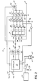
- FIG. 2 shows an exemplary layout for circuit charger and charge control components suited for incorporation into the system 10 of FIG. 1 .
- the charger and charge control system 12 is operably configured to fully charge four lithium-ion cells 14 to a voltage in the range of about 4.1 volts to about 4.2 volts with a voltage input to the charger and charge control system 12 in the range of about 4.1 to 4.5 volts per cell 14 .
- charge control circuitry interconnects and works in tandem with charging circuitry in such a manner as to control the amount of current and voltage supplied to and from the battery cells 14 .
- a controller 32 monitors current and voltage supplied to and voltage across four, series-connected lithium-ion cells 14 .
- the controller 32 brokers power supplied from the external source 20 to the lithium-ion cells 14 through input terminals 22 , 24 .
- the power source may comprise a direct current (DC) power source 20 that is external to a battery housing 15 and have an input voltage of about 16 to about 18 volts.
- the controller 32 may receive, manipulate and deliver current from the input terminals 22 , 24 to an inductor 34 via a set of switchable transistors 36 , 38 .
- the inductor 34 In response to the current, the inductor 34 creates an electromotive force that it supplies to the lithium-ion cells 14 through battery terminals 26 , 28 .
- the inductor 34 may be placed in series with the switchable transistors 36 , 38 to smooth the current leaving the controller 32 .
- the switchable transistors 36 , 38 in part, serve to convert DC power supplied via the input terminals 22 , 24 to alternating current (AC). The conversion facilitates system efficiency by mitigating power propagation losses associated with DC power.
- the placement of the controller 32 along the current supply path from the power source input terminals 22 , 24 to the lithium-ion cells 14 allows the controller 32 to manipulate the type and amount of power supplied to the cells 14 .
- the controller 32 can readily enable or disable the switchable transistors 36 , 38 , which are configured to break or complete the supply circuit to the battery terminals 26 , 28 .
- the controller 32 manipulates the charge across the lithium-ion cells 14 .
- this measure of control further permits the charger and charge control system 12 to conduct simultaneous discharge and charging operations.
- the controller 32 accounts for and coordinates requirements of both the load 30 and the power source 20 .
- the controller 32 monitors individual voltages of the lithium-ion cells 14 to account for high or low voltage conditions in each cell 14 .
- a designer may specify basement and ceiling voltage parameters for each cell. Unheeded, such voltage extremes could result in damage to charger and charge control system 12 and cells 14 , while harming system performance.
- a bank of differential amplifiers 40 shown in FIG. 2 work in concert with a series of comparators 42 , 44 to report individual cell voltages to the controller 32 .
- differing ages, compositions and other characteristics of each lithium-ion cell 14 can cause them to charge and discharge at different rates. Consequently, one cell may reach or exceed a target voltage while the others continue to charge in parallel. Such a scenario could result in the cell exceeding a critical voltage level prior to the others reaching the target voltage, ultimately harming the cell and impeding system performance.
- the differential amplifiers 40 are positioned such that they measure the voltage across each lithium-ion cell 14 relative to its placement within the charger and charge control system 12 . Because the battery cells 14 are connected in series, each differential amplifier 40 connects to the top and bottom of respective cells 14 in order to detect the ceiling and basement voltage measurements associated with each cell 14 .
- each differential amplifier 40 outputs a voltage value to an input prong of a comparator 42 , 44 indicative of the respective cell 14 .
- the comparator 42 , 44 generates a binary signal in response to detecting that the voltage at one input prong is higher than at a second.
- the input driven by one of the operational amplifiers 40 is compared to one of two reference voltages.
- these reference voltages may include a basement and a ceiling voltage reference embodied by each bank of comparators 44 , 42 , respectively.
- the reference voltages may be electronically achieved using resistor configurations 46 , 48 in parallel with the comparators 42 , 44 as shown in FIG. 2 .
- a prong of the first bank of comparators 42 may be correlated to a maximum voltage level or ceiling threshold voltage tolerated by a single lithium-ion cell 14 in a given charging scheme. That is, a charge exceeding the ceiling voltage may result in a cell 14 going critical and becoming damaged. While an operator may adjust the ceiling reference as appropriate to a particular application, the ceiling threshold voltage and comparator 42 inputs are preferably correlated to about 4.3 volts.
- the comparator 42 generates a binary signal that is conveyed back to the controller 32 in response to registering that the voltage sampled from a differential amplifier 40 exceeds the 4.3 volt ceiling reference threshold voltage.
- the binary signal from the comparator 42 communicates to the controller 32 that the voltage across the respective lithium-ion cell 14 has exceeded the specified ceiling threshold voltage. Absent such notification, the voltage in the cell 14 would continue to rise undetected, damaging the hardware and compromising system performance.
- the controller 32 intervenes by breaking the circuit between the input terminals 22 , 24 and the lithium-ion cells 14 . Namely, the controller 32 disables one of the switchable transistors 36 or 38 positioned between the controller 32 and the battery terminals 26 , 28 . This disconnect opens the circuit leading to the lithium-ion cells 14 .
- the charger and charge control system 12 embodiment incorporates hysterisis principles to avoid oscillation within the charging regime. Such oscillation could result if an inadequate amount of time is allowed for cell 14 recovery in between charging applications. Namely, the voltage in a cell 14 may not have sufficient time to retreat to a voltage level that is low enough to ensure that a resumption of power to the cell 14 does not immediately cause its associated voltage to return to a critical state. Consequently, the embodiment may wait for the voltage in the cell to drop an additional 200 millivolts before re-engaging both switchable transistors 36 , 38 . This provision allows for more gradual recovery within the cells 14 .
- a comparator 50 sends a resume signal to the controller 32 . More particularly, the differential amplifier 40 measuring the charge across the critical lithium-ion cell 14 will relate the charge to the comparator 50 .
- the comparator 50 evaluates the charge against a hysterisis voltage hardwired into the comparator 50 .
- a preferred hysterisis voltage may be set at around 4.1 volts. Accordingly, the controller 32 will receive the resume signal from the comparator 50 when the voltage measured across the lithium-ion cell 14 matches that of the hysterisis reference voltage.
- This subsequent signal instructs the controller 32 to resume charging operations across all lithium-ion cells 14 .
- the respective charges across the cells 14 have equalized while the comparator 50 waited for voltage to drop in the critical cell 14 , the intermittent power supply has effectively postured the cells 14 to charge more evenly.
- Such a charging regiment permits each lithium-ion cell 14 to achieve maximum capacity and extends cell longevity over time.
- the charger and charge control system 12 shown in FIG. 2 additionally monitors and corrects low voltage conditions across each cell 14 . Such conditions can arise at instances when the lithium-ion cells 14 provide charge to the load 30 at a rate faster than charge is replenished to the same. As above, differing characteristics of each lithium-ion cell 14 can give rise to varying rates of voltage discharge. Consequently, the differential amplifier combination 40 additionally detects and reports to the controller 32 measured incidences occurring below a basement threshold voltage.
- the differential amplifiers 40 measure the voltage across each lithium-ion cell 14 to detect a sub-critical condition. Such a condition can signal system failure and cell 14 damage.
- the differential amplifiers 40 convey the voltage measurement to a respective bank of comparators 44 .
- These comparators 42 are configured to evaluate the voltage measurement relative to the basement threshold voltage limit, which is supplied to an input prong of the comparators 42 .
- a resistor 48 may be placed in parallel with the comparators 44 of FIG. 2 to determine the basement reference voltage.
- a preferred basement threshold voltage may correspond to around 2.75 volts. Should a comparator 44 register that the measured voltage of an individual lithium-ion cell 14 falls below the basement threshold voltage, that comparator 44 will accordingly generate a low voltage signal.
- the comparator 44 will disable a third switchable transistor 52 leading to the output terminals 31 , 33 and to the load 30 .
- the transistor 52 acts as a switch enabling discharge of voltage from the lithium-ion cells 14 to the load 30 .
- the load 30 may no longer drain voltage across the cells 14 .
- the cells 14 may uniformly recharge via the enabled charging transistors 36 , 38 . More particularly, current can flow from the input ports 22 , 24 to the lithium-ion cells 14 through the controller 32 and charging transistors 36 , 38 , ultimately arriving at the battery terminals 26 , 28 .
- the battery charger and charge control system 12 simultaneously accommodates both charge and discharge operations during normal use. That is, the controller 32 may continue to allow power to be relayed to the lithium-ion cells 14 so long as the voltage across each cell remains above the basement threshold voltage. Thus, the lithium-ion cells 14 may charge irrespective of load 30 requirements when operating within the preset voltage boundaries. Conversely, requirements of the load 30 do not impede charging operations. The controller 32 may continue to broker voltage and current from the power supply terminals 22 , 24 to the lithium-ion cells 14 so long as voltage across any one cell 14 does not exceed the maximum, ceiling threshold voltage limit.
- the exemplary charger and charge control system 12 may further be sensitive to high temperature conditions present in the battery housing 15 . Unaddressed, such conditions can impede system performance and cause damage to electrical components. For instance, heat accumulation will lower the conductivity of wiring within the charger and charge control system 12 by increasing resistive characteristics of the same. This increased resistance translates into the generation of still more heat. Although the charger and charge control system 12 is optimized to dissipate relatively small quantities of heat, provisions are nonetheless made for instances where voltage within the housing 15 may cause the temperature within the cells 14 to rise to an unacceptable level. Consequently, the charger and charge control system 12 shown in the embodiment of FIG. 2 provides mechanisms adapted to both detect and correct such potentially harmful conditions.
- a negative temperature coefficient thermistor 54 imbedded with in the battery housing 15 converts ambient temperature detected within the housing into an electrical signal.
- comparator 56 evaluates the electrical signal from the thermistor 54 with regard to a reference temperature voltage.
- the reference voltage preferably correlates to around 55° C.
- Such an ambient temperature condition approaches a temperature mark that could become critical if allowed to further escalate. That is, an internal temperature associated with the comparator 56 will transmit an alerting signal to the controller 32 in response to the electrical signal from the thermistor 54 corresponding to the reference temperature voltage.
- the controller 32 In response to the alerting signal, the controller 32 disables one of the switchable transistors 36 or 38 as above to disconnect the input terminals 22 , 24 from the lithium-ion cells 14 .
- temperature within the housing 15 will dissipate until the thermistor 54 registers an ambient temperature of approximately 50° C.
- the hysterisis set by resistor 58 will cause the temperature comparator 56 to generate a signal configured to prompt the controller 32 to re-engage the disabled switchable transistor 36 or 38 .
- the charger and charge control system 12 may resume charging the cells 14 in a safe manner.
- the controller 32 may disconnect the charging circuit in response to either a high temperature or a high voltage condition. Such precaution translates into longer cell life and improved system performance.
- typical lithium-ion cells 14 perform optimally in dual modes. Namely, lithium-ion cells 14 conventionally operate in both constant voltage and constant current modes for electrochemical considerations. For instance, such dual mode operation improves cell life and performance characteristics over time.
- the controller 32 may accordingly be preconfigured to manage dual operating modes. As such, the controller 32 causes a constant flow of current to initially charge the lithium-ion cells 14 until the controller 32 senses that they have become fully charged. More particularly, as the lithium-ion cells 14 approach full charge, current drawn from the power source 20 will dwindle. The diminished flow of current registers with the resister 59 , and in turn, the controller 32 . That is, the controller 32 measures current across a resistor 59 to determine when the lithium-ion cells 14 draw less than some preset amperage. An exemplary measurement preferably corresponds to 300 milliamps of current.
- the controller 32 may illuminate a green component 61 of an LED 62 .
- the LED 62 communicates to an operator that the lithium-ion cells 14 are filly charged without the user having to perform a labor intensive disassembly or testing procedure.
- the controller 32 may illuminate a yellow component 63 of the LED 62 while greater quantities of current flow through the resister 59 in order to indicate that the lithium-ion cells 14 are charging normally.
- the dual signal LED 62 may be substituted with multiple LED's, sound signals, computer network transmissions, or any notification sequence/mechanism appropriate to a given application.
- the charging algorithm of the controller 32 may continuously measure voltage across the inductor 34 .
- the controller 32 manipulates the duty cycles of the switchable transistors 36 , 38 to supply constant voltage to the BAT+ and BAT ⁇ terminals 26 , 28 .
- the controller 32 may switch to voltage mode whenever voltage measured across the inductor 34 reaches around 16.8 volts. As such, the controller 32 will continue to maintain a constant voltage across the lithium-ion cells 14 absent an interruption in power.
- FIG. 3 illustrates exemplary steps suited to charge four lithium-ion cells 14 with an input voltage in the range of about 4.1 to about 4.5 volts per cell.
- the illustrative method steps are preferably executed by the charger and charge control system 12 operating within the confines of a single battery housing 15 .
- an exemplary charging sequence begins at block 60 in constant current mode.
- the controller 32 is preferably preconfigured to charge in either constant current or voltage mode according to the operational state of the cells 14 .
- the controller 32 operates in both current and voltage modes to realize electrochemical efficiencies particular to lithium-ion cells 14 .
- the controller 32 initiates a charge supply to the lithium-ion cells 14 while in constant current mode in response to detecting a voltage across the inductor 34 of FIG. 2 . More specifically, the controller 32 performs a soft start at block 60 of FIG. 3 .
- the controller 32 initially ramps up current to the lithium-ion cells 14 when a charge across the inductor 34 reaches approximately 8.3 volts.
- the controller 32 subsequently senses around 13 volts across the inductor 34 , it provides a constant current level of about 1.5 amps at block 60 .
- the controller 32 will initiate the illumination of a yellow LED 62 at block 62 .
- the controller 32 and associated circuitry will monitor for several conditions at blocks 64 , 68 , 76 , 86 , 92 and 96 . While in constant current mode, one such condition includes sensing a second voltage measurement across the inductor 34 at block 64 . Namely, the controller 32 will determine if the voltage across the inductor 34 has achieved a transition voltage of about 16.8 volts. If so, the embodiment will accordingly adjust operating mode to constant voltage operation at block 66 . As such, the controller 32 will provide a charge sufficient to maintain a constant voltage of around 16.8 volts across the cells 14 .
- control circuitry While operating in either mode, control circuitry simultaneously measures the voltage across each individual lithium-ion cell as shown at block 68 of FIG. 3 .
- comparators 42 , 44 work in conjunction with differential amplifiers 40 to report the voltage across each cell to the controller 32 .
- the controller 32 will break a switchable transistor connection at block 70 .
- the switchable transistor at block 70 By disabling the switchable transistor at block 70 , current is diverted away from the lithium-ion cells 14 . This feature enables the voltage across the critical lithium-ion cell to dissipate.
- the controller 32 may continue to monitor the voltage across the cell at block 72 . Should it determine that the voltage across the cell has diminished to about 4.1 volts at block 74 , then the controller 32 will reenable the switchable transistor at block 75 . The switchable transistor will again complete the circuit from the controller 32 to the lithium-ion cells 14 . Consequently, the controller 32 resumes charging operations as before. In this manner, the controller 32 manipulates the duty cycles of the switchable transistors 36 , 38 to control voltage across the lithium-ion cells 14 .
- the controller 32 and sensing circuitry of the embodiment provide a measure of hysterisis between blocks 70 and 75 , in that voltage preferably decays about 200 milliamps before the switchable transistor is again enabled. This feature prevents oscillations that could otherwise hinder charging performance and potentially damage hardware over time.
- the controller 32 further monitors ambient temperature conditions within the lithium-ion battery housing 15 . Namely, a thermistor 54 buried within the housing 15 transmits an electrical signal to the controller 32 should the temperature within the housing 15 exceed a preferable setting of about 55° C.
- the controller 32 will break the switchable transistors 36 , 38 as above at block 78 . This action of disabling the switchable transistor will allow voltage and subsequently, the heat within the housing 15 to dissipate while the charging circuit remains broken.
- the controller 32 will monitor signals from the thermistor 54 until the temperature within the housing 15 preferably registers at around 50° C. at block 82 . A 50° C. measurement will cause the controller 32 to re-engage the disabled switchable transistor at block 75 . After bridging the approximately five degrees of hysterisis provided by the charging regiment, charging operations resume as before the temperature occurrence.
- the controller 32 in conjunction with the amplifiers 40 and comparators 42 , 44 , will continue to monitor voltage across the critical cell at block 89 until its associated voltage recovers to around three volts. Once voltage in the cell has recovered as such at block 90 , then the controller 32 will resume power supply to the load 30 by re-engaging the disabled transistor at block 75 .
- the exemplary three volt recovery is preferably set such that the critical cell has achieved a charge sufficient to avoid oscillations associated with inadequate hysterisis as discussed above.
- the controller 32 will continue charging the lithium-ion cells 14 until current consumed by the cells 14 diminishes to a measurement of approximately 20% of their maximum draw at block 92 . In response, the controller 32 will illuminate a green LED 62 at block 94 to indicate fall charge to the user.
- the embodiment will resume charging in constant current mode at block 60 .
Abstract
Description
Claims (51)
Priority Applications (2)
| Application Number | Priority Date | Filing Date | Title |
|---|---|---|---|
| US10/051,402 US6518726B1 (en) | 2002-01-18 | 2002-01-18 | Battery charger and charge control system |
| PCT/US2003/001357 WO2003063319A1 (en) | 2002-01-18 | 2003-01-17 | Battery charger and charge control system |
Applications Claiming Priority (1)
| Application Number | Priority Date | Filing Date | Title |
|---|---|---|---|
| US10/051,402 US6518726B1 (en) | 2002-01-18 | 2002-01-18 | Battery charger and charge control system |
Publications (1)
| Publication Number | Publication Date |
|---|---|
| US6518726B1 true US6518726B1 (en) | 2003-02-11 |
Family
ID=21971077
Family Applications (1)
| Application Number | Title | Priority Date | Filing Date |
|---|---|---|---|
| US10/051,402 Expired - Lifetime US6518726B1 (en) | 2002-01-18 | 2002-01-18 | Battery charger and charge control system |
Country Status (2)
| Country | Link |
|---|---|
| US (1) | US6518726B1 (en) |
| WO (1) | WO2003063319A1 (en) |
Cited By (16)
| Publication number | Priority date | Publication date | Assignee | Title |
|---|---|---|---|---|
| US20040263123A1 (en) * | 2003-06-24 | 2004-12-30 | Dell Products L.P. | Battery and system power selector integration scheme |
| US20050269986A1 (en) * | 2004-06-04 | 2005-12-08 | Ta-Min Peng | Charger |
| US20060132091A1 (en) * | 2004-12-17 | 2006-06-22 | Sigmatel, Inc. | System, method and semiconductor device for charging a secondary battery |
| US20070069690A1 (en) * | 2005-09-26 | 2007-03-29 | United States Of America As Represented By The Secretary Of The Navy | Battery charger and power reduction system and method |
| US20070088769A1 (en) * | 2004-02-20 | 2007-04-19 | Mainstar Software Corporation | Reorganization and repair of an icf catalog while open and in-use in a digital data storage system |
| US20070188134A1 (en) * | 2006-02-16 | 2007-08-16 | Summit Microelectronics, Inc | Switching battery charging systems and methods |
| US20070188139A1 (en) * | 2006-02-16 | 2007-08-16 | Summit Microelectronics, Inc | System and method of charging a battery using a switching regulator |
| US7528574B1 (en) | 2006-02-16 | 2009-05-05 | Summit Microelectronics, Inc. | Systems and methods of programming voltage and current in a battery charger |
| US20100194345A1 (en) * | 2009-02-05 | 2010-08-05 | Guo Xing Li | Multi-cell battery pack protection circuit |
| US20130221918A1 (en) * | 2010-04-26 | 2013-08-29 | Proterra Inc | Fast charge stations for electric vehicles in areas with limited power availabilty |
| US20150004474A1 (en) * | 2013-07-01 | 2015-01-01 | Samsung Sdl Co., Ltd. | Secondary battery |
| US8933669B2 (en) | 2012-11-08 | 2015-01-13 | Peak Power & Mfg., Inc. | Reclaiming energy stored in rechargeable batteries for charging other batteries |
| US20150321577A1 (en) * | 2012-08-29 | 2015-11-12 | Toyota Jidosha Kabushiki Kaisha | Power storage system and temperature control method for the same |
| CN105449315A (en) * | 2014-09-18 | 2016-03-30 | 李尔公司 | Traction battery heater control |
| US10250048B2 (en) | 2014-12-31 | 2019-04-02 | Huawei Technologies Co., Ltd. | Charging protection method and apparatus |
| US11715963B1 (en) | 2020-04-29 | 2023-08-01 | The United States Of America, As Represented By The Secretary Of The Navy | Battery storage container and wellness system |
Citations (15)
| Publication number | Priority date | Publication date | Assignee | Title |
|---|---|---|---|---|
| US5432429A (en) | 1990-10-23 | 1995-07-11 | Benchmarq Microelectronics, Inc. | System for charging/monitoring batteries for a microprocessor based system |
| US5767659A (en) | 1991-10-30 | 1998-06-16 | Texas Instruments Incorporated | Batteries and battery systems |
| US5831350A (en) | 1995-12-15 | 1998-11-03 | Compaq Computer Corporation | System using interchangeable nickel-based and lithium ion battery packs |
| US5898294A (en) | 1997-08-19 | 1999-04-27 | Polystor Corporation | Control loop for pulse charging lithium ion cells |
| US5955869A (en) | 1996-07-17 | 1999-09-21 | Rathmann; Roland | Battery pack and a method for monitoring remaining capacity of a battery pack |
| US5973477A (en) | 1998-12-16 | 1999-10-26 | Creation Intelligence Technology Co., Ltd. | Multi-purpose battery mobile phones |
| US5994874A (en) | 1997-05-13 | 1999-11-30 | Nec Corporation | Battery charging system with battery pack of different charging voltages using common a battery charger |
| US6025698A (en) | 1997-08-25 | 2000-02-15 | Daewoo Telecom Ltd. | Smart battery charging system, charging method therefor and power supply system for portable computer using the same |
| US6040685A (en) * | 1996-08-16 | 2000-03-21 | Total Battery Management, Inc. | Energy transfer and equalization in rechargeable lithium batteries |
| US6060864A (en) | 1994-08-08 | 2000-05-09 | Kabushiki Kaisha Toshiba | Battery set structure and charge/discharge control apparatus for lithium-ion battery |
| US6118254A (en) | 1999-07-30 | 2000-09-12 | Compaq Computer Corporation | Battery charge control architecture for constant voltage maximum power operation |
| US6198250B1 (en) * | 1998-04-02 | 2001-03-06 | The Procter & Gamble Company | Primary battery having a built-in controller to extend battery run time |
| US6326767B1 (en) * | 1999-03-30 | 2001-12-04 | Shoot The Moon Products Ii, Llc | Rechargeable battery pack charging system with redundant safety systems |
| US6377028B1 (en) * | 1990-10-23 | 2002-04-23 | Texas Instruments Incorporated | System for charging monitoring batteries for a microprocessor based method |
| US6403251B1 (en) * | 2000-01-31 | 2002-06-11 | Moltech Power Systems, Inc | Battery pack with multiple secure modules |
-
2002
- 2002-01-18 US US10/051,402 patent/US6518726B1/en not_active Expired - Lifetime
-
2003
- 2003-01-17 WO PCT/US2003/001357 patent/WO2003063319A1/en not_active Application Discontinuation
Patent Citations (15)
| Publication number | Priority date | Publication date | Assignee | Title |
|---|---|---|---|---|
| US6377028B1 (en) * | 1990-10-23 | 2002-04-23 | Texas Instruments Incorporated | System for charging monitoring batteries for a microprocessor based method |
| US5432429A (en) | 1990-10-23 | 1995-07-11 | Benchmarq Microelectronics, Inc. | System for charging/monitoring batteries for a microprocessor based system |
| US5767659A (en) | 1991-10-30 | 1998-06-16 | Texas Instruments Incorporated | Batteries and battery systems |
| US6060864A (en) | 1994-08-08 | 2000-05-09 | Kabushiki Kaisha Toshiba | Battery set structure and charge/discharge control apparatus for lithium-ion battery |
| US5831350A (en) | 1995-12-15 | 1998-11-03 | Compaq Computer Corporation | System using interchangeable nickel-based and lithium ion battery packs |
| US5955869A (en) | 1996-07-17 | 1999-09-21 | Rathmann; Roland | Battery pack and a method for monitoring remaining capacity of a battery pack |
| US6040685A (en) * | 1996-08-16 | 2000-03-21 | Total Battery Management, Inc. | Energy transfer and equalization in rechargeable lithium batteries |
| US5994874A (en) | 1997-05-13 | 1999-11-30 | Nec Corporation | Battery charging system with battery pack of different charging voltages using common a battery charger |
| US5898294A (en) | 1997-08-19 | 1999-04-27 | Polystor Corporation | Control loop for pulse charging lithium ion cells |
| US6025698A (en) | 1997-08-25 | 2000-02-15 | Daewoo Telecom Ltd. | Smart battery charging system, charging method therefor and power supply system for portable computer using the same |
| US6198250B1 (en) * | 1998-04-02 | 2001-03-06 | The Procter & Gamble Company | Primary battery having a built-in controller to extend battery run time |
| US5973477A (en) | 1998-12-16 | 1999-10-26 | Creation Intelligence Technology Co., Ltd. | Multi-purpose battery mobile phones |
| US6326767B1 (en) * | 1999-03-30 | 2001-12-04 | Shoot The Moon Products Ii, Llc | Rechargeable battery pack charging system with redundant safety systems |
| US6118254A (en) | 1999-07-30 | 2000-09-12 | Compaq Computer Corporation | Battery charge control architecture for constant voltage maximum power operation |
| US6403251B1 (en) * | 2000-01-31 | 2002-06-11 | Moltech Power Systems, Inc | Battery pack with multiple secure modules |
Cited By (35)
| Publication number | Priority date | Publication date | Assignee | Title |
|---|---|---|---|---|
| US7202631B2 (en) * | 2003-06-24 | 2007-04-10 | Dell Products L.P. | Battery and system power selector integration scheme |
| US20040263123A1 (en) * | 2003-06-24 | 2004-12-30 | Dell Products L.P. | Battery and system power selector integration scheme |
| US7982430B2 (en) | 2003-06-24 | 2011-07-19 | Dell Products L.P. | Battery and system power selector integration scheme |
| US20070132430A1 (en) * | 2003-06-24 | 2007-06-14 | Dell Products L.P. | Battery and system power selector integration scheme |
| US20070088769A1 (en) * | 2004-02-20 | 2007-04-19 | Mainstar Software Corporation | Reorganization and repair of an icf catalog while open and in-use in a digital data storage system |
| US6977484B1 (en) * | 2004-06-04 | 2005-12-20 | C.Q.S. Electrical Products Inc. | Charger |
| US20050269986A1 (en) * | 2004-06-04 | 2005-12-08 | Ta-Min Peng | Charger |
| US20090212739A1 (en) * | 2004-12-17 | 2009-08-27 | Sigmatel, Inc. | Charging A Secondary Battery |
| US20060132091A1 (en) * | 2004-12-17 | 2006-06-22 | Sigmatel, Inc. | System, method and semiconductor device for charging a secondary battery |
| US7501794B2 (en) | 2004-12-17 | 2009-03-10 | Sigmatel, Inc. | System, method and semiconductor device for charging a secondary battery |
| US7786698B2 (en) | 2004-12-17 | 2010-08-31 | Sigmatel, Inc. | Charging a secondary battery |
| US20070069690A1 (en) * | 2005-09-26 | 2007-03-29 | United States Of America As Represented By The Secretary Of The Navy | Battery charger and power reduction system and method |
| US7573235B2 (en) | 2005-09-26 | 2009-08-11 | The Unites States Of America As Repsented By The Secretary Of The Navy | Battery charger and power reduction system and method |
| US7834591B2 (en) | 2006-02-16 | 2010-11-16 | Summit Microelectronics, Inc. | Switching battery charging systems and methods |
| US8471533B2 (en) | 2006-02-16 | 2013-06-25 | Qualcomm Incorporated | System and method of charging a battery using a switching regulator |
| US7528574B1 (en) | 2006-02-16 | 2009-05-05 | Summit Microelectronics, Inc. | Systems and methods of programming voltage and current in a battery charger |
| US20070188139A1 (en) * | 2006-02-16 | 2007-08-16 | Summit Microelectronics, Inc | System and method of charging a battery using a switching regulator |
| US7880445B2 (en) | 2006-02-16 | 2011-02-01 | Summit Microelectronics, Inc. | System and method of charging a battery using a switching regulator |
| US20110025277A1 (en) * | 2006-02-16 | 2011-02-03 | Summit Microelectroics, Inc. | Switching battery charging systems and methods |
| US20110089893A1 (en) * | 2006-02-16 | 2011-04-21 | Summit Microelectronics, Inc. | System and Method of Charging a Battery Using a Switching Regulator |
| US20070188134A1 (en) * | 2006-02-16 | 2007-08-16 | Summit Microelectronics, Inc | Switching battery charging systems and methods |
| US8193780B2 (en) | 2006-02-16 | 2012-06-05 | Summit Microelectronics, Inc. | System and method of charging a battery using a switching regulator |
| US8981733B2 (en) | 2006-02-16 | 2015-03-17 | Qualcomm Incorporated | System and method of charging a battery using a switching regulator |
| TWI395964B (en) * | 2009-02-05 | 2013-05-11 | O2Micro Int Ltd | Voltage detection circuit ,circuit and methods for multi-cell battery pack protection |
| US20100194345A1 (en) * | 2009-02-05 | 2010-08-05 | Guo Xing Li | Multi-cell battery pack protection circuit |
| US8253383B2 (en) * | 2009-02-05 | 2012-08-28 | O2Micro Inc | Circuits and methods for monitoring multi-cell battery packs |
| US20130221918A1 (en) * | 2010-04-26 | 2013-08-29 | Proterra Inc | Fast charge stations for electric vehicles in areas with limited power availabilty |
| US20150321577A1 (en) * | 2012-08-29 | 2015-11-12 | Toyota Jidosha Kabushiki Kaisha | Power storage system and temperature control method for the same |
| US9873343B2 (en) * | 2012-08-29 | 2018-01-23 | Toyota Jidosha Kabushiki Kaisha | Power storage system and temperature control method for the same |
| US8933669B2 (en) | 2012-11-08 | 2015-01-13 | Peak Power & Mfg., Inc. | Reclaiming energy stored in rechargeable batteries for charging other batteries |
| US20150004474A1 (en) * | 2013-07-01 | 2015-01-01 | Samsung Sdl Co., Ltd. | Secondary battery |
| CN105449315A (en) * | 2014-09-18 | 2016-03-30 | 李尔公司 | Traction battery heater control |
| US10250048B2 (en) | 2014-12-31 | 2019-04-02 | Huawei Technologies Co., Ltd. | Charging protection method and apparatus |
| US10778018B2 (en) | 2014-12-31 | 2020-09-15 | Huawei Technologies Co., Ltd. | Charging protection method and apparatus |
| US11715963B1 (en) | 2020-04-29 | 2023-08-01 | The United States Of America, As Represented By The Secretary Of The Navy | Battery storage container and wellness system |
Also Published As
| Publication number | Publication date |
|---|---|
| WO2003063319A1 (en) | 2003-07-31 |
Similar Documents
| Publication | Publication Date | Title |
|---|---|---|
| US6518726B1 (en) | Battery charger and charge control system | |
| US20200119568A1 (en) | System and method for charging a battery pack | |
| TWI680626B (en) | Power receiving device, control circuit, electronic device, and operation method of power supply system | |
| US5557188A (en) | Smart battery system and interface | |
| US7595609B2 (en) | Battery system power path configuration and methods for implementing same | |
| US9035609B1 (en) | Hot swap control in uninterruptible power supply | |
| CN110062994B (en) | Apparatus and method for preventing overcharge | |
| US7969119B2 (en) | Overvoltage protection | |
| US8687338B2 (en) | Systems and methods for enhanced protection systems for storage batteries | |
| KR101182890B1 (en) | System for controlling charging of battery pack | |
| US5786682A (en) | Battery charging circuit including a current limiter which compares a reference current to a charging current to ensure operation of a load | |
| US8035354B2 (en) | Battery full-charge detection for charge-and-play circuits | |
| EP1304787A1 (en) | Charger, battery pack, and charging system using the charger and battery pack | |
| US20070024243A1 (en) | Trickle discharge for battery pack protection | |
| KR101193167B1 (en) | Battery pack, charger and charging system | |
| JP2011137805A (en) | Battery pack and disconnection detection method therefor | |
| JP2007129898A (en) | Power supply system | |
| KR101147231B1 (en) | Battery pack and method for controlling of charging and dischraging of the same | |
| EP3806274A2 (en) | Charging integrated circuit and operating method | |
| CN113410897A (en) | Battery power transmission system | |
| JP2011187227A (en) | Battery pack, electronic equipment, equipment system, control method for battery pack cooling unit, and program | |
| US7605565B2 (en) | Battery pack with protection circuit | |
| JP2003174720A (en) | Secondary battery protective circuit and protective circuit ic | |
| KR101875536B1 (en) | Method of UPS battery charge | |
| JP2007042396A (en) | Battery pack, and electric apparatus equipped with it |
Legal Events
| Date | Code | Title | Description |
|---|---|---|---|
| AS | Assignment |
Owner name: EAGLE-PICHER TECHNOLOGIES, L.L.C., MISSOURI Free format text: ASSIGNMENT OF ASSIGNORS INTEREST;ASSIGNORS:NOWLIN JR., RONALD D.;THRONEBERRY, HEATH;MCCORKLE, DONNIE M.;AND OTHERS;REEL/FRAME:012947/0279;SIGNING DATES FROM 20020307 TO 20020415 |
|
| STCF | Information on status: patent grant |
Free format text: PATENTED CASE |
|
| AS | Assignment |
Owner name: GENERAL ELECTRIC CAPITAL CORPORATION, CONNECTICUT Free format text: FIRST LIEN PATENT SECURITY AGREEMENT;ASSIGNOR:EAGLEPICHER INCORPORATED;REEL/FRAME:017025/0113 Effective date: 20051230 |
|
| AS | Assignment |
Owner name: OBSIDIAN, LLC, AS COLLATERAL AGENT UNDER THIRD LIE Free format text: SECURITY AGREEMENT;ASSIGNORS:EAGLEPICHER FILTRATION & MINERALS, INC.;EAGLEPICHER AUTOMOTIVE, INC.;EAGLEPICHER TECHNOLOGIES LLC;REEL/FRAME:017025/0938 Effective date: 20051230 Owner name: GOLDMAN SACHS CREDIT PARTNERS L.P., NEW YORK Free format text: SECOND LIEN PATENT SECURITY AGREEMENT;ASSIGNOR:GENERAL ELECTRIC CAPITAL CORPORATION;REEL/FRAME:017025/0355 Effective date: 20051230 Owner name: GOLDMAN SACHS CREDIT PARTNERS L.P., NEW YORK Free format text: CORRECTIVE ASSIGNMENT TO CORRECT THE ASSIGNOR'S NAME PREVIOUSLY RECORDED ON REEL 017025 FRAME 0355;ASSIGNOR:EAGLEPICHER INCORPORATED;REEL/FRAME:017025/0648 Effective date: 20051230 |
|
| FPAY | Fee payment |
Year of fee payment: 4 |
|
| AS | Assignment |
Owner name: GENERAL ELECTRIC CAPITAL CORPORATION, CONNECTICUT Free format text: SECURITY AGREEMENT;ASSIGNORS:HILLSDALE AUTOMOTIVE, LLC;NEW EAGLEPICHER TECHNOLOGIES, LLC;WOLVERINE ADVANCED MATERIALS, LLC;AND OTHERS;REEL/FRAME:018061/0210 Effective date: 20060731 Owner name: GOLDMAN SACHS CREDIT PARTNERS L.P., NEW JERSEY Free format text: SECOND LIEN PATENT SECURITY AGREEMENT;ASSIGNORS:HILLSDALE AUTOMOTIVE, LLC;NEW EAGLEPICHER TECHNOLOGIES, LLC;WOLVERINE ADVANCED MATERIALS, LLC;AND OTHERS;REEL/FRAME:018061/0255 Effective date: 20060731 |
|
| AS | Assignment |
Owner name: NEW EAGLEPICHER TECHNOLOGIES, LLC, MISSOURI Free format text: ASSIGNMENT OF ASSIGNORS INTEREST;ASSIGNOR:EAGLEPICHER TECHNOLOGIES LLC;REEL/FRAME:018184/0689 Effective date: 20060727 Owner name: EAGLEPICHER TECHNOLOGIES, LLC, MISSOURI Free format text: CHANGE OF NAME;ASSIGNOR:EAGLE-PICHER TECHNOLOGIES, LLC;REEL/FRAME:018184/0561 Effective date: 20030401 |
|
| AS | Assignment |
Owner name: WOLVERINE ADVANCED MATERIALS, LLC, MICHIGAN Free format text: RELEASE BY SECURED PARTY;ASSIGNOR:GOLDMAN SACHS CREDIT PARTNERS, LP;REEL/FRAME:020478/0657 Effective date: 20071231 Owner name: EAGLEPICHER TECHNOLOGIES, LLC (F/K/A NEW EAGLEPICH Free format text: RELEASE BY SECURED PARTY;ASSIGNOR:GOLDMAN SACHS CREDIT PARTNERS, LP;REEL/FRAME:020478/0657 Effective date: 20071231 Owner name: EAGLEPICHER MANAGEMENT COMPANY, MICHIGAN Free format text: RELEASE BY SECURED PARTY;ASSIGNOR:GOLDMAN SACHS CREDIT PARTNERS, LP;REEL/FRAME:020478/0657 Effective date: 20071231 Owner name: EAGLEPICHER CORPORATION (F/K/A NEW EAGLEPICHER COR Free format text: RELEASE BY SECURED PARTY;ASSIGNOR:GOLDMAN SACHS CREDIT PARTNERS, LP;REEL/FRAME:020478/0657 Effective date: 20071231 Owner name: HILLSDALE AUTOMOTIVE, LLC, MICHIGAN Free format text: RELEASE BY SECURED PARTY;ASSIGNOR:GOLDMAN SACHS CREDIT PARTNERS, LP;REEL/FRAME:020478/0657 Effective date: 20071231 |
|
| AS | Assignment |
Owner name: OBSIDIAN, LLC, AS COLLATERAL AGENT, CALIFORNIA Free format text: SHORT FORM INTELLECTUAL PROPERTY SECURITY AGREEMENT;ASSIGNORS:EAGLEPICHER CORPORATION;HILLSDALE AUTOMOTIVE, LLC;EP MINERALS, LLC;AND OTHERS;REEL/FRAME:020723/0038 Effective date: 20071231 Owner name: GENERAL ELECTRIC CAPITAL CORPORATION, AS COLLATERA Free format text: SHORT FORM INTELLECTUAL PROPERTY SECURITY AGREEMENT;ASSIGNORS:EAGLEPICHER CORPORATION;HILLSDALE AUTOMOTIVE, LLC;EP MINERALS, LLC;AND OTHERS;REEL/FRAME:020710/0871 Effective date: 20071231 |
|
| AS | Assignment |
Owner name: EAGLEPICHER TECHNOLOGIES, LLC, MISSOURI Free format text: CHANGE OF NAME;ASSIGNOR:NEW EAGLEPICHER TECHNOLOGIES, LLC;REEL/FRAME:022331/0572 Effective date: 20060731 |
|
| AS | Assignment |
Owner name: EAGLEPICHER TECHNOLOGIES, LLC, OHIO Free format text: PARTIAL RELEASE OF AMENDED AND RESTATED PATENT SECURITY AGREEMENT RECORDED AT REEL 020710/FRAME 0871;ASSIGNOR:GENERAL ELECTRIC CAPITAL CORPORATION, AS COLLATERAL AGENT;REEL/FRAME:023870/0428 Effective date: 20100129 Owner name: EAGLEPICHER TECHNOLOGIES, LLC,OHIO Free format text: PARTIAL RELEASE OF AMENDED AND RESTATED PATENT SECURITY AGREEMENT RECORDED AT REEL 020710/FRAME 0871;ASSIGNOR:GENERAL ELECTRIC CAPITAL CORPORATION, AS COLLATERAL AGENT;REEL/FRAME:023870/0428 Effective date: 20100129 Owner name: EAGLEPICHER TECHNOLOGIES, LLC,MICHIGAN Free format text: PARTIAL RELEASE OF AMENDED AND RESTATED PATENT SECURITY AGREEMENT RECORDED AT REEL 020723 FRAME 0038;ASSIGNOR:OBSIDIAN, LLC AS COLLATERAL AGENT;REEL/FRAME:023892/0847 Effective date: 20100129 Owner name: EAGLEPICHER TECHNOLOGIES, LLC, MICHIGAN Free format text: PARTIAL RELEASE OF AMENDED AND RESTATED PATENT SECURITY AGREEMENT RECORDED AT REEL 020723 FRAME 0038;ASSIGNOR:OBSIDIAN, LLC AS COLLATERAL AGENT;REEL/FRAME:023892/0847 Effective date: 20100129 |
|
| AS | Assignment |
Owner name: PNC BANK, NATIONAL ASSOCIATION,PENNSYLVANIA Free format text: SECURITY AGREEMENT;ASSIGNORS:OM GROUP, INC.;OMG AMERICAS, INC.;OMG ELECTRONIC CHEMICALS, INC.;AND OTHERS;REEL/FRAME:024066/0130 Effective date: 20100308 Owner name: PNC BANK, NATIONAL ASSOCIATION, PENNSYLVANIA Free format text: SECURITY AGREEMENT;ASSIGNORS:OM GROUP, INC.;OMG AMERICAS, INC.;OMG ELECTRONIC CHEMICALS, INC.;AND OTHERS;REEL/FRAME:024066/0130 Effective date: 20100308 |
|
| FPAY | Fee payment |
Year of fee payment: 8 |
|
| AS | Assignment |
Owner name: EAGLEPICHER INCORPORATED, MICHIGAN Free format text: RELEASE OF THIRD LIEN PATENT SECURITY AGREEMENT RECORDED AT REEL 017025/FRAME 0938;ASSIGNOR:OBSIDIAN, LLC;REEL/FRAME:025459/0234 Effective date: 20100920 |
|
| AS | Assignment |
Owner name: EAGLEPICHER INCORPORATED, MICHIGAN Free format text: RELEASE BY SECURED PARTY;ASSIGNOR:GENERAL ELECTRIC CAPITAL CORPORATION, AS COLLATERAL AGENT;REEL/FRAME:026692/0607 Effective date: 20110526 |
|
| AS | Assignment |
Owner name: OMG AMERICAS, INC., A OHIO CORPORATION, OHIO Free format text: PATENT RELEASE AGREEMENT;ASSIGNOR:PNC BANK, NATIONAL ASSOCIATION, AS ADMINISTRATIVE AGENT;REEL/FRAME:026727/0485 Effective date: 20110802 Owner name: EPEP HOLDING COMPANY, LLC, A DELAWARE LIMITED LIAB Free format text: PATENT RELEASE AGREEMENT;ASSIGNOR:PNC BANK, NATIONAL ASSOCIATION, AS ADMINISTRATIVE AGENT;REEL/FRAME:026727/0485 Effective date: 20110802 Owner name: OMG ENERGY HOLDINGS, INC., A DELAWARE CORPORATION, Free format text: PATENT RELEASE AGREEMENT;ASSIGNOR:PNC BANK, NATIONAL ASSOCIATION, AS ADMINISTRATIVE AGENT;REEL/FRAME:026727/0485 Effective date: 20110802 Owner name: OMG ELECTRONIC CHEMICALS, INC., A DELAWARE LIMITED Free format text: PATENT RELEASE AGREEMENT;ASSIGNOR:PNC BANK, NATIONAL ASSOCIATION, AS ADMINISTRATIVE AGENT;REEL/FRAME:026727/0485 Effective date: 20110802 Owner name: EAGLEPICHER TECHNOLOGIES, LLC, A DELAWARE LIMITED Free format text: PATENT RELEASE AGREEMENT;ASSIGNOR:PNC BANK, NATIONAL ASSOCIATION, AS ADMINISTRATIVE AGENT;REEL/FRAME:026727/0485 Effective date: 20110802 Owner name: EAGLEPICHER MEDICAL POWER, LLC, A DELAWARE LIMITED Free format text: PATENT RELEASE AGREEMENT;ASSIGNOR:PNC BANK, NATIONAL ASSOCIATION, AS ADMINISTRATIVE AGENT;REEL/FRAME:026727/0485 Effective date: 20110802 Owner name: OM GROUP, INC., A DELAWARE CORPORATION, OHIO Free format text: PATENT RELEASE AGREEMENT;ASSIGNOR:PNC BANK, NATIONAL ASSOCIATION, AS ADMINISTRATIVE AGENT;REEL/FRAME:026727/0485 Effective date: 20110802 Owner name: COMPUGRAPHICS U.S.A. INC., A DELAWARE CORPORATION, Free format text: PATENT RELEASE AGREEMENT;ASSIGNOR:PNC BANK, NATIONAL ASSOCIATION, AS ADMINISTRATIVE AGENT;REEL/FRAME:026727/0485 Effective date: 20110802 |
|
| AS | Assignment |
Owner name: BANK OF AMERICA, N.A., AS COLLATERAL AGENT, TEXAS Free format text: SECURITY AGREEMENT;ASSIGNORS:OM GROUP, INC., A DELAWARE CORPORATION;COMPUGRAPHICS U.S.A. INC., A DELAWARE CORPORATION;CYANTEK CORPORATION, A DELAWARE CORPORATION;AND OTHERS;REEL/FRAME:026740/0353 Effective date: 20110802 |
|
| AS | Assignment |
Owner name: EAGLEPICHER TECHNOLOGIES, LLC, MISSOURI Free format text: RELEASE BY SECURED PARTY;ASSIGNOR:BANK OF AMERICA, N.A.;REEL/FRAME:031169/0976 Effective date: 20130903 Owner name: EAGLEPICHER MEDICAL POWER, LLC, TEXAS Free format text: RELEASE BY SECURED PARTY;ASSIGNOR:BANK OF AMERICA, N.A.;REEL/FRAME:031169/0976 Effective date: 20130903 Owner name: OM GROUP, INC., OHIO Free format text: RELEASE BY SECURED PARTY;ASSIGNOR:BANK OF AMERICA, N.A.;REEL/FRAME:031169/0976 Effective date: 20130903 Owner name: OMG AMERICAS, INC., OHIO Free format text: RELEASE BY SECURED PARTY;ASSIGNOR:BANK OF AMERICA, N.A.;REEL/FRAME:031169/0976 Effective date: 20130903 Owner name: OMG ELECTRONIC CHEMICALS, LLC, MINNESOTA Free format text: RELEASE BY SECURED PARTY;ASSIGNOR:BANK OF AMERICA, N.A.;REEL/FRAME:031169/0976 Effective date: 20130903 |
|
| AS | Assignment |
Owner name: PNC BANK, PENNSYLVANIA Free format text: SECURITY AGREEMENT;ASSIGNORS:OM GROUP, INC.;OMG ELECTRONIC CHEMICALS, LLC;OMG AMERICAS, INC.;AND OTHERS;REEL/FRAME:031208/0876 Effective date: 20130904 |
|
| FPAY | Fee payment |
Year of fee payment: 12 |
|
| AS | Assignment |
Owner name: EAGLEPICHER TECHNOLOGIES, LLC, MISSOURI Free format text: TERMINATION AND RELEASE OF SECURITY INTEREST IN PATENTS;ASSIGNOR:PNC BANK;REEL/FRAME:036985/0642 Effective date: 20151028 |
|
| AS | Assignment |
Owner name: CREDIT SUISSE AG, CAYMAN ISLANDS BRANCH, AS COLLAT Free format text: SECURITY INTEREST;ASSIGNOR:EAGLEPICHER TECHNOLOGIES, LLC;REEL/FRAME:037311/0571 Effective date: 20151028 |
|
| AS | Assignment |
Owner name: CREDIT SUISSE AG, CAYMAN ISLANDS BRANCH, AS COLLAT Free format text: SECURITY INTEREST;ASSIGNOR:EAGLEPICHER TECHNOLOGIES, LLC;REEL/FRAME:037459/0921 Effective date: 20151028 |
|
| AS | Assignment |
Owner name: EAGLEPICHER TECHNOLOGIES, LLC, MISSOURI Free format text: TERMINATION AND RELEASE OF SECURITY INTEREST IN PATENTS (SECOND LIEN);ASSIGNOR:CREDIT SUISSE AG, CAYMAN ISLANDS BRANCH;REEL/FRAME:041777/0090 Effective date: 20170221 |
|
| AS | Assignment |
Owner name: EAGLEPICHER TECHNOLOGIES, LLC, MISSOURI Free format text: TERMINATION AND RELEASE OF SECURITY INTEREST IN PATENTS (FIRST LIEN);ASSIGNOR:CREDIT SUISSE AG, CAYMAN ISLANDS BRANCH;REEL/FRAME:045539/0138 Effective date: 20180308 Owner name: EAGLEPICHER TECHNOLOGIES, LLC, MISSOURI Free format text: TERMINATION AND RELEASE OF SECURITY INTEREST IN PATENTS (SECOND LIEN);ASSIGNOR:CREDIT SUISSE AG, CAYMAN ISLANDS BRANCH;REEL/FRAME:045539/0225 Effective date: 20180308 |
|
| AS | Assignment |
Owner name: JEFFERIES FINANCE LLC, NEW YORK Free format text: FIRST LIEN INTELLECTUAL PROPERTY SECURITY AGREEMENT;ASSIGNOR:EAGLEPICHER TECHNOLOGIES, LLC;REEL/FRAME:045545/0508 Effective date: 20180308 Owner name: JEFFERIES FINANCE LLC, NEW YORK Free format text: SECOND LIEN INTELLECTUAL PROPERTY SECURITY AGREEMENT;ASSIGNOR:EAGLEPICHER TECHNOLOGIES, LLC;REEL/FRAME:045545/0893 Effective date: 20180308 |
|
| AS | Assignment |
Owner name: DUKE FINANCE SUBSIDIARY HOLDINGS, LLC, MISSOURI Free format text: RELEASE AND TERMINATION OF LIEN ON PATENTS (2L);ASSIGNOR:JEFFERIES FINANCE LLC;REEL/FRAME:065222/0001 Effective date: 20231011 Owner name: EAGLEPICHER TECHNOLOGIES, LLC, MISSOURI Free format text: RELEASE AND TERMINATION OF LIEN ON PATENTS (2L);ASSIGNOR:JEFFERIES FINANCE LLC;REEL/FRAME:065222/0001 Effective date: 20231011 Owner name: VECTRA CO., MISSOURI Free format text: RELEASE AND TERMINATION OF LIEN ON PATENTS (2L);ASSIGNOR:JEFFERIES FINANCE LLC;REEL/FRAME:065222/0001 Effective date: 20231011 Owner name: DUKE FINANCE SUBSIDIARY HOLDINGS, LLC, MISSOURI Free format text: RELEASE AND TERMINATION OF LIEN ON PATENTS (1L);ASSIGNOR:JEFFERIES FINANCE LLC;REEL/FRAME:065221/0832 Effective date: 20231011 Owner name: EAGLEPICHER TECHNOLOGIES, LLC, MISSOURI Free format text: RELEASE AND TERMINATION OF LIEN ON PATENTS (1L);ASSIGNOR:JEFFERIES FINANCE LLC;REEL/FRAME:065221/0832 Effective date: 20231011 Owner name: VECTRA CO., MISSOURI Free format text: RELEASE AND TERMINATION OF LIEN ON PATENTS (1L);ASSIGNOR:JEFFERIES FINANCE LLC;REEL/FRAME:065221/0832 Effective date: 20231011 |