US6504556B1 - Operator notation tool tip - Google Patents
Operator notation tool tip Download PDFInfo
- Publication number
- US6504556B1 US6504556B1 US09/342,373 US34237399A US6504556B1 US 6504556 B1 US6504556 B1 US 6504556B1 US 34237399 A US34237399 A US 34237399A US 6504556 B1 US6504556 B1 US 6504556B1
- Authority
- US
- United States
- Prior art keywords
- stock
- tool tip
- operator
- printing system
- icons
- Prior art date
- Legal status (The legal status is an assumption and is not a legal conclusion. Google has not performed a legal analysis and makes no representation as to the accuracy of the status listed.)
- Expired - Lifetime
Links
- 108091008695 photoreceptors Proteins 0.000 claims description 25
- 239000000463 material Substances 0.000 claims description 23
- 238000012546 transfer Methods 0.000 claims description 12
- 238000000034 method Methods 0.000 claims description 11
- 239000002245 particle Substances 0.000 claims description 10
- 238000004140 cleaning Methods 0.000 claims description 7
- 230000037361 pathway Effects 0.000 claims description 5
- 238000012545 processing Methods 0.000 claims description 5
- 239000011230 binding agent Substances 0.000 claims description 4
- 238000011161 development Methods 0.000 description 8
- 238000003384 imaging method Methods 0.000 description 7
- 230000008569 process Effects 0.000 description 7
- 239000000843 powder Substances 0.000 description 5
- 238000012986 modification Methods 0.000 description 4
- 230000004048 modification Effects 0.000 description 4
- 239000002131 composite material Substances 0.000 description 3
- 230000006870 function Effects 0.000 description 3
- 238000006243 chemical reaction Methods 0.000 description 2
- 238000010586 diagram Methods 0.000 description 2
- 238000003491 array Methods 0.000 description 1
- 230000008859 change Effects 0.000 description 1
- 239000011248 coating agent Substances 0.000 description 1
- 238000000576 coating method Methods 0.000 description 1
- 239000003086 colorant Substances 0.000 description 1
- 238000004891 communication Methods 0.000 description 1
- 238000012937 correction Methods 0.000 description 1
- 230000001934 delay Effects 0.000 description 1
- 238000007599 discharging Methods 0.000 description 1
- 150000002500 ions Chemical class 0.000 description 1
- 238000007726 management method Methods 0.000 description 1
- 239000011159 matrix material Substances 0.000 description 1
- 230000035699 permeability Effects 0.000 description 1
- 238000000926 separation method Methods 0.000 description 1
- 239000007921 spray Substances 0.000 description 1
- 239000000758 substrate Substances 0.000 description 1
Images


Classifications
-
- G—PHYSICS
- G06—COMPUTING; CALCULATING OR COUNTING
- G06F—ELECTRIC DIGITAL DATA PROCESSING
- G06F3/00—Input arrangements for transferring data to be processed into a form capable of being handled by the computer; Output arrangements for transferring data from processing unit to output unit, e.g. interface arrangements
- G06F3/01—Input arrangements or combined input and output arrangements for interaction between user and computer
- G06F3/048—Interaction techniques based on graphical user interfaces [GUI]
- G06F3/0481—Interaction techniques based on graphical user interfaces [GUI] based on specific properties of the displayed interaction object or a metaphor-based environment, e.g. interaction with desktop elements like windows or icons, or assisted by a cursor's changing behaviour or appearance
-
- G—PHYSICS
- G03—PHOTOGRAPHY; CINEMATOGRAPHY; ANALOGOUS TECHNIQUES USING WAVES OTHER THAN OPTICAL WAVES; ELECTROGRAPHY; HOLOGRAPHY
- G03G—ELECTROGRAPHY; ELECTROPHOTOGRAPHY; MAGNETOGRAPHY
- G03G15/00—Apparatus for electrographic processes using a charge pattern
- G03G15/50—Machine control of apparatus for electrographic processes using a charge pattern, e.g. regulating differents parts of the machine, multimode copiers, microprocessor control
- G03G15/5075—Remote control machines, e.g. by a host
- G03G15/5083—Remote control machines, e.g. by a host for scheduling
-
- G—PHYSICS
- G03—PHOTOGRAPHY; CINEMATOGRAPHY; ANALOGOUS TECHNIQUES USING WAVES OTHER THAN OPTICAL WAVES; ELECTROGRAPHY; HOLOGRAPHY
- G03G—ELECTROGRAPHY; ELECTROPHOTOGRAPHY; MAGNETOGRAPHY
- G03G15/00—Apparatus for electrographic processes using a charge pattern
- G03G15/50—Machine control of apparatus for electrographic processes using a charge pattern, e.g. regulating differents parts of the machine, multimode copiers, microprocessor control
- G03G15/5075—Remote control machines, e.g. by a host
- G03G15/5087—Remote control machines, e.g. by a host for receiving image data
-
- G—PHYSICS
- G06—COMPUTING; CALCULATING OR COUNTING
- G06K—GRAPHICAL DATA READING; PRESENTATION OF DATA; RECORD CARRIERS; HANDLING RECORD CARRIERS
- G06K15/00—Arrangements for producing a permanent visual presentation of the output data, e.g. computer output printers
-
- G—PHYSICS
- G06—COMPUTING; CALCULATING OR COUNTING
- G06K—GRAPHICAL DATA READING; PRESENTATION OF DATA; RECORD CARRIERS; HANDLING RECORD CARRIERS
- G06K15/00—Arrangements for producing a permanent visual presentation of the output data, e.g. computer output printers
- G06K15/002—Interacting with the operator
- G06K15/007—Interacting with the operator only remotely, e.g. at a host computer
-
- G—PHYSICS
- G03—PHOTOGRAPHY; CINEMATOGRAPHY; ANALOGOUS TECHNIQUES USING WAVES OTHER THAN OPTICAL WAVES; ELECTROGRAPHY; HOLOGRAPHY
- G03G—ELECTROGRAPHY; ELECTROPHOTOGRAPHY; MAGNETOGRAPHY
- G03G15/00—Apparatus for electrographic processes using a charge pattern
- G03G15/50—Machine control of apparatus for electrographic processes using a charge pattern, e.g. regulating differents parts of the machine, multimode copiers, microprocessor control
- G03G15/5016—User-machine interface; Display panels; Control console
- G03G15/502—User-machine interface; Display panels; Control console relating to the structure of the control menu, e.g. pop-up menus, help screens
-
- G—PHYSICS
- G03—PHOTOGRAPHY; CINEMATOGRAPHY; ANALOGOUS TECHNIQUES USING WAVES OTHER THAN OPTICAL WAVES; ELECTROGRAPHY; HOLOGRAPHY
- G03G—ELECTROGRAPHY; ELECTROPHOTOGRAPHY; MAGNETOGRAPHY
- G03G2215/00—Apparatus for electrophotographic processes
- G03G2215/00025—Machine control, e.g. regulating different parts of the machine
- G03G2215/00109—Remote control of apparatus, e.g. by a host
-
- Y—GENERAL TAGGING OF NEW TECHNOLOGICAL DEVELOPMENTS; GENERAL TAGGING OF CROSS-SECTIONAL TECHNOLOGIES SPANNING OVER SEVERAL SECTIONS OF THE IPC; TECHNICAL SUBJECTS COVERED BY FORMER USPC CROSS-REFERENCE ART COLLECTIONS [XRACs] AND DIGESTS
- Y10—TECHNICAL SUBJECTS COVERED BY FORMER USPC
- Y10S—TECHNICAL SUBJECTS COVERED BY FORMER USPC CROSS-REFERENCE ART COLLECTIONS [XRACs] AND DIGESTS
- Y10S715/00—Data processing: presentation processing of document, operator interface processing, and screen saver display processing
- Y10S715/961—Operator interface with visual structure or function dictated by intended use
- Y10S715/965—Operator interface with visual structure or function dictated by intended use for process control and configuration
Definitions
- the present invention relates to a printing system, and more particularly to a user interface having an operator notation tool tip for navigating and controlling a printing system to generate documents received from one or more input units including a computer network, scanner, modem, etc.
- a user friendly tool which can provide the operator with information regarding the printing supplies available for completing print jobs.
- a user friendly tool which permits operators to create their own tool to identify certain supplies, which are repeatedly used for print jobs, which may or may not have been listed by the manufacturer in a stock library of the user interface.
- a graphical user interface provides stock profiles to be used by a printing system on a display screen comprising a depiction of a stock library including stock icons on the display screen, a cursor highlighting stock icons, and an operator notation tool tip identifying stocks in the stock library when stock icons are highlighted.
- a graphical user interface for associating a tray with stock from the stock library displayed on a display screen comprising a depiction of a printing system shown on the display screen including at least one tray icon, a depiction of a pathway access window including a stock library icon, a depiction of a stock library including stock icons on the display screen, an operator notation tool tip identifying stocks in the stock library when stock icons are highlighted, and means for dragging one of the stock icons into the one tray icon to associate the one stock with the one tray.
- a printing system for printing image data received from a computer network, scanner or other image data generating device on a support material comprising: a supply unit having a plurality of feeders, wherein each feeder has at least one tray for storing support material; a controller including a system controller processing the received image data, and a user interface comprising: a depiction of a stock library including stock icons on the display screen, a cursor highlighting stock icons, and an operator notation tool tip identifying stocks in the stock library when stock icons are highlighted; a print engine including a charging unit charging a surface of a photoconductive belt, at least one exposure unit exposing a photoconductive belt to create an electrostatic latent image based on the received image data at the direction of the system controller, at least one developer unit having charged toner particles, which are attracted to the electrostatic latent image, a transfer unit receiving support material and transferring the toner from the photoreceptor belt to the support material, a fuser assembly receiving the support material from the transfer unit and permanently affixing the toner to the
- a method for associating a tray in a printing system with a stock comprising the steps of: accessing a stock library, searching the stock library for the stock, creating a new stock profile and an operator tool tip associated with the stock profile when the search is unsuccessful, and associating the new stock profile with the tray in the printing system.
- FIG. 1 shows a digital printing system into which the preferred embodiments may be incorporated
- FIG. 2 is a general block diagram of the printing system shown in FIG. 1;
- FIG. 3 is a general diagram of a few of the components of the user interface shown in FIG. 2;
- FIG. 4 is a view depicting an exemplary graphical representation of printer status window and pathway access window displayed on a user interface screen of the printing system shown in FIGS. 1 and 2;
- FIG. 5 is a view depicting an exemplary graphical representation of a stock library displayed on a user interface screen of the printing system shown in FIGS. 1 and 2;
- FIG. 6 is a view depicting an exemplary graphical representation of a stock settings and attributes window displayed on a user interface screen of the printing system shown in FIGS. 1 and 2;
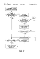
- FIG. 7 is a flow chart showing steps for the operator notation tool tip of the user interface of the present invention.
- FIG. 8 is a flow chart showing further steps for the operator notation tool tip of the user interface of the present invention.
- FIG. 9 is a partial schematic elevational view of an example of a printing system employing the operator notation tool tip of the present invention.
- FIG. 1 shows a digital printing system 10 of the type suitable for use with the preferred embodiment for processing print jobs.
- the digital printing system includes document feeders 20 , a print engine 30 , finishers 40 and controller 50 .
- the digital printing system 10 is coupled to an image input section 60 .
- the image input section 60 transmits signals to the controller 50 .
- image input section 60 has both remote and onsite image inputs, enabling the digital printing system 10 to provide network, scan and print services.
- the remote image input is a computer network 62
- the onsite image input is a scanner 64 .
- the digital printing system 10 can be coupled to multiple networks or scanning units, remotely or onsite.
- Other systems can be envisioned such as stand alone digital printing system with on-site image input, controller and printer. While a specific digital printing system is shown and described, the present invention may be used with other types of printing systems such as analog printing systems.
- the digital printing system 10 receives image data, which can include pixels, in the form of digital image signals for processing from the computer network 62 by way of a suitable communication channel, such as a telephone line, computer cable, ISDN line, etc.
- a suitable communication channel such as a telephone line, computer cable, ISDN line, etc.
- computer networks 62 include clients who generate jobs, wherein each job includes the image data in the form of a plurality of electronic pages and a set of processing instructions.
- each job is converted into a representation written in a page description language (PDL) such as PostScript® containing the image data.
- PDL page description language
- a suitable conversion unit converts the incoming PDL to the PDL used by the digital printing system.
- the suitable conversion unit may be located in an interface unit 52 in the controller 50 .
- Other remote sources of image data such as a floppy disk, hard disk, storage medium, scanner, etc. may be envisioned.
- an operator may use the scanner 64 to scan documents, which provides digital image signals including pixels to the interface unit 52 .
- the interface unit 52 processes the digital image signals into digital image data in a form required to carry out each programmed job.
- the interface unit 52 is preferably part of the digital printing system 10 .
- the computer network 62 or the scanner 64 may share the function of converting the digital image signals into digital image data in the form, which can be unutilized by the digital printing system 10 .
- the digital printing system 10 includes one or more (1 to N) feeders 20 , a print engine 30 , one or more (1 to M) finishers 40 and controller 50 .
- Each feeder 20 preferably includes one or more trays, which forward different types of support material to the print engine 30 .
- All of the feeders 20 in the digital printing system 10 are collectively referred to as a supply unit 25 .
- All of the finishers 40 are collectively referred to as an output unit 45 .
- the output unit 45 may comprise several types of finishers 40 such as inserters, stackers, staplers, binders, etc., which take the completed pages from the print engine 30 and use them to provide a finished product.
- the controller 50 controls and monitors the entire digital printing system 10 and interfaces with both on-site and remote input units in the image input section 60 .
- the controller 50 includes the interface unit 52 , a system control unit 54 , a memory 56 and a user interface 58 .
- the user interface 58 includes an area holding a graphic representation or picture of the feeders 20 , print engine 30 and finishers 40 of the digital printing system 10 .
- the user interface 58 permits an operator to monitor the document feeders 20 , print engine 30 and finishers 40 by navigating through a series of menus by clicking on a section of the graphical representation of the user interface 58 to reach controls or information related to that component of the digital printing system 10 .
- the user interface 58 preferably includes a mouse 53 , a keyboard 55 and a display unit 57 having a display screen 59 as shown in FIG. 3 .
- FIGS. 4-6 show menus and graphical representations displayed on a display screen 59 , and used to reach controls or information related to stock (support materials) in the digital printing system 10 .
- FIG. 4 shows a printer status window 70 having a printer icon 72 including feeder icons A-D, print engine icon E, and finisher icons F-J. However, as indicated above, feeder icons and finisher icons can be added or removed so that the printer icon 72 is an accurate depiction of the printing system actually being used by the operator.
- a cursor 71 is used to highlight icons on the display screen 59 .
- the printer status window 70 also includes a job progress icon 74 , which continuously informs the operator of the total time required to complete a print job (e.g. 33 minutes), the time that has elapsed since the print job began (e.g. 28 minutes) and the time remaining (7 minutes). This enables the operator to make choices as to whether to stop or suspend the current job in order to process a higher priority job.
- FIG. 4 also shows a pathway access window 76 , which also provides access to information and control of the digital printing system 10 .
- a stock library 80 as shown in FIG. 5 appears on the display screen 59 .
- the stock profile 82 of this particular stock is displayed on the display screen 59 as shown in FIG. 6 .
- the stock profile lists stock attributes, which preferably include color, paper weight, size, coating and preprinting. It is understood that this list of attributes is not exhaustive.
- highlighting a clicking on an icon is only an example of one way of displaying menus. Double clicking, highlighting, single clicking, etc. can be used alone or in combination to display menus.
- the window 84 provides the operator with the opportunity to enter or change the operator notation tool tip as described below
- FIGS. 7-8 show the process for creating, modifying or utilizing an operator tool tip for selecting stock for a print job. If a different stock is required by the system, this stock is currently programmed, and loaded in a tray of a feeder 20 , the digital printing system 10 continues the print job with this stock. If this stock is not loaded, the operator loads this stock into a tray of a feeder 20 so that the print job can continue.
- a stock is programmed when the stock is associated with a tray. This is accomplished by dragging the stock icon from the stock library window onto the tray icon.
- the stock library 80 is accessed to determine if a profile for the stock exists by highlighting the icons in the stock library 80 with the cursor 71 as shown in FIGS. 5 and 6. By highlighting the icons, the operator notation tool tip 85 for each icon is displayed. By clicking on the highlighted icon, the stock profile 82 of the icon is displayed. If the operator finds the appropriate stock profile 82 using this method, the stock is programmed by associating the stock with a tray. If the stock is loaded, the system continues the print job using this stock. However, if the stock is not loaded, the operator loads the stock to continue the print job.
- the operator tool tip 85 can be changed by the operator. For example, if the stock profile 82 did not exist, then the operator could enter a new stock profile by entering new stock attributes. By entering text, symbols, etc. into the window 84 below the “Stock Notes” in FIG. 6, a custom operator tool tip is established for that stock. In a second example, if the stock was provided by the manufacturer and the default tool-tip provided by the manufacturer is not adequate, then the operator could enter a new operator tool tip by editing the window 84 in FIG. 6 . On default, the identification number for the stock is repeated as the operator tool tip.
- the operator can still search through the stock library 80 using other stock attributes. Once, the appropriate stock is found, the window 84 in FIG. 6 can be edited to provide a custom operator tool tip. The tool tip should now be adequate. After the operator tool tip is customized, the stock profile is closed. Then, the operator programs the stock. If the stock is loaded, the system continues the print job using this stock. However, if the stock is not loaded, the operator loads the stock to continue the print job.
- FIG. 9 is a partial schematic view of a digital printing system, such as the digital imaging system of U.S. application Ser. No. 09/318,953, utilizing the graphical user interface and operator tool tip of the present invention.
- the imaging system is used to produce color output in a single pass of a photoreceptor belt. It will be understood, however, that it is not intended to limit the invention to the embodiment disclosed. On the contrary, it is intended to cover all alternatives, modifications and equivalents as may be included within the spirit and scope of the invention as defined by the appended claims, including a multiple pass color process system, a single or multiple pass highlight color system and a black and white printing system.
- the present invention is applicable to a printing system having a print engine with any number of developer housings.
- an original document can be positioned in a document handler 110 on a raster-input scanner (RIS) indicated generally by reference numeral 112 .
- RIS raster-input scanner
- the RIS 112 captures the entire original document and converts it to a series of raster scan lines or image signals.
- This information is transmitted to an electronic subsystem (ESS) or system controller 54 by way of user interface 52 .
- System controller 54 includes a pixel counter, and is connected to a user interface 58 .
- image signals may be supplied by a computer network 62 by way of user interface 52 .
- the print engine preferably uses a charge retentive surface in the form of an Active Matrix (AMAT) photoreceptor belt 150 supported for movement in the direction indicated by arrow 152 , for advancing sequentially through the various xerographic process stations.
- AMAT Active Matrix
- the photoreceptor belt 150 is entrained about a drive roller 154 , tension rollers 156 and fixed roller 158 and the drive roller 154 is operatively connected to a drive motor 160 for effecting movement of the photoreceptor belt 150 through the xerographic stations.
- a portion of photoreceptor belt 150 passes through charging station A where a corona generating device, indicated generally by the reference numeral 162 , charges the photoconductive surface of photoreceptor belt 150 to a relatively high, substantially uniform, preferably negative potential.
- the system controller 54 receives the image signals from raster input scanner 66 by way of the interface unit 52 .
- the image signals represent the desired output image.
- the system controller 54 processes these signals to convert them to the various color separations of the image which is transmitted to a laser based output scanning device, which causes the charge retentive surface to be discharged in accordance with the output from the scanning device.
- the laser based scanning device is a laser Raster Output Scanner (ROS) 164 .
- ROS 164 could be replaced by other xerographic exposure devices such as LED arrays.
- a computer network 62 may also transmit image signals to the system controller 54 by way of the interface unit 52 .
- the photoreceptor belt 150 which is initially charged to a voltage V 0 , undergoes dark decay to a level equal to about ⁇ 500 volts. When exposed at the exposure station B, it is discharged to a level equal to about ⁇ 50 volts. Thus after exposure, the photoreceptor belt 150 contains a monopolar voltage profile of high and low voltages, the former corresponding to charged areas and the latter corresponding to discharged or background areas.
- developer structure indicated generally by the reference numeral 166 utilizing a hybrid development system
- the development roll is powered by two development fields (potentials across an air gap).
- the first field is the ac field which is used for toner cloud generation.
- the second field is the dc development field which is used to control the amount of developed toner mass on the photoreceptor belt 150 .
- the developer structure 166 contains magenta toner particles 168 .
- the toner cloud causes charged magenta toner particles 168 to be attracted to the electrostatic latent image.
- Appropriate developer biasing is accomplished via a power supply.
- This type of system is a noncontact type in which only toner particles (magenta, for example) are attracted to the latent image and there is no mechanical contact between the photoreceptor belt 150 and a toner delivery device to disturb a previously developed, but unfixed, image.
- a toner concentration sensor 170 senses the toner concentration in the developer structure 166 .
- a toner dispenser 190 adds new toner particles 168 to increase the toner concentration in the developer structure 166 at developer station C.
- the developed but unfixed image is then transported past a second charging device 180 where the photoreceptor belt 150 and previously developed toner image areas are recharged to a predetermined level.
- a second exposure/imaging is performed by device 182 .
- Device 182 preferably comprises a laser based output structure and is preferably utilized for selectively discharging the photoreceptor belt 150 on toned areas and/or is bare areas, pursuant to the image to be developed with the second color toner.
- Device 182 may be a raster output scanner or LED window.
- the photoreceptor belt 150 contains toned and untoned areas at relatively high voltage levels and toned and untoned areas at relatively low voltage levels. These low voltage areas represent image areas which are developed using discharged area development (DAD).
- DAD discharged area development
- a negatively charged, developer material 184 comprising color toner, preferably yellow, is employed.
- the toner which by way of example may be yellow, is contained in a developer structure 166 disposed at a second developer station D and is presented to the latent images on the photoreceptor belt 150 by way of a second developer system.
- a power supply (not shown) serves to electrically bias the developer structure 166 to a level effective to develop the discharged image areas with negatively charged yellow toner particles 184 .
- a toner concentration sensor 170 senses the toner concentration in the developer structure 166 .
- a toner dispenser 190 adds new toner particles 184 to increase the concentration in the developer structure 166 at developer station D.
- a permeability sensor 200 measures developed mass per unit area. Although only one mass sensor 200 is shown in FIG. 9, there may be more than one mass sensor 200 .
- a negative pre-transfer dicorotron member 214 is provided to condition all of the toner for effective transfer to a substrate using positive corona discharge.
- a sheet of support material 212 from supply unit 25 is moved into contact with the toner images at transfer station G.
- the sheet of support material 212 is advanced to transfer station G by the supply unit 25 .
- the sheet of support material 212 is then brought into contact with photoconductive surface of photoreceptor belt 150 in a timed sequence so that the toner powder image developed thereon contacts the advancing sheet of support material 212 at transfer station G.
- Transfer station G includes a transfer dicorotron 214 which sprays positive ions onto the backside of support material 212 . This attracts the negatively charged toner powder images from the photoreceptor belt 150 to sheet 212 .
- a detack dicorotron 216 is provided for facilitating stripping of the sheets from the photoreceptor belt 150 .
- Fusing station H includes a fuser assembly, indicated generally by the reference numeral 220 , which permanently affixes the transferred powder image to sheet 212 .
- fuser assembly 220 comprises a heated fuser roller 222 and a backup or pressure roller 224 .
- Sheet 212 passes between fuser roller 222 and backup roller 224 with the toner powder image contacting fuser roller 222 . In this manner, the toner powder images are permanently affixed to sheet 212 .
- a chute guides the advancing sheets 212 to the output unit 45 , which includes one or more finishers 40 such as a catch tray, stacker, binder, stapler or other output device, for subsequent removal from the printing system by the operator.
- finishers 40 such as a catch tray, stacker, binder, stapler or other output device
- the residual toner particles carried by the non-image areas on the photoconductive surface are removed therefrom. These particles are removed at cleaning station 1 , preferably using a cleaning brush or plural brush structure contained in a housing 230 .
- the cleaning brush 240 or brushes 240 are engaged after the composite toner image is transferred to a sheet. Once the photoreceptor belt 150 is cleaned the brushes 240 are retracted utilizing a device incorporating a clutch (not shown) so that the next imaging and development cycle can begin.
- System controller 54 regulates the various printer functions.
- the system controller 54 is preferably a programmable controller, which controls printer functions hereinbefore described.
- the system controller 54 may provide a comparison count of the copy sheets, the number of documents being recirculated, the number of copy sheets selected by the operator, time delays, jam corrections, etc.
- the control of all of the exemplary systems heretofore described may be accomplished by conventional control switch inputs from the printing machine consoles selected by an operator.
- Conventional sheet path sensors or switches may be utilized to keep track of the position of the document and the copy sheets.
Abstract
Description
Claims (4)
Priority Applications (2)
| Application Number | Priority Date | Filing Date | Title |
|---|---|---|---|
| US09/342,373 US6504556B1 (en) | 1999-06-29 | 1999-06-29 | Operator notation tool tip |
| BR0002896-7A BR0002896A (en) | 1999-06-29 | 2000-06-29 | Operator notation tool tip |
Applications Claiming Priority (1)
| Application Number | Priority Date | Filing Date | Title |
|---|---|---|---|
| US09/342,373 US6504556B1 (en) | 1999-06-29 | 1999-06-29 | Operator notation tool tip |
Publications (1)
| Publication Number | Publication Date |
|---|---|
| US6504556B1 true US6504556B1 (en) | 2003-01-07 |
Family
ID=23341558
Family Applications (1)
| Application Number | Title | Priority Date | Filing Date |
|---|---|---|---|
| US09/342,373 Expired - Lifetime US6504556B1 (en) | 1999-06-29 | 1999-06-29 | Operator notation tool tip |
Country Status (2)
| Country | Link |
|---|---|
| US (1) | US6504556B1 (en) |
| BR (1) | BR0002896A (en) |
Cited By (16)
| Publication number | Priority date | Publication date | Assignee | Title |
|---|---|---|---|---|
| US20020097422A1 (en) * | 2001-01-23 | 2002-07-25 | Xerox Corporation | Fault notes user interface for a printing system |
| US20020135793A1 (en) * | 2001-01-19 | 2002-09-26 | Walgrove George R. | Apparatus and method for a programmable detack charging system |
| NL1023326C2 (en) * | 2003-05-02 | 2004-11-03 | Oce Tech Bv | Printing system and method for using this system. |
| EP1473660A1 (en) * | 2003-05-02 | 2004-11-03 | Océ-Technologies B.V. | A method of using a print system |
| US20050138573A1 (en) * | 2000-06-05 | 2005-06-23 | Sharp Laboratories Of America | Printer driver with automatic inquiry of user preferences |
| US20050154998A1 (en) * | 2000-06-05 | 2005-07-14 | Sharp Laboratories Of America, Inc. | Peripheral device driver with automatic inquiry of user preferences |
| EP1555580A2 (en) * | 2004-01-15 | 2005-07-20 | Xerox Corporation | Feeder control system and method |
| US20050179929A1 (en) * | 2004-02-17 | 2005-08-18 | Oracle International Corporation | System and method for detecting accidental output to a device |
| US6964024B2 (en) * | 2001-02-07 | 2005-11-08 | Xerox Corporation | Operator-defined visitation sequence of client user interface controls |
| US20050283728A1 (en) * | 2004-06-15 | 2005-12-22 | Lothar Pfahlmann | Method for graphical presentation of objects and technical processes on a screen and computer program product used for this purpose |
| US20060123341A1 (en) * | 2004-11-23 | 2006-06-08 | Samsung Electronics Co., Ltd. | Apparatus and method for adaptively generating tooltip |
| US20070016611A1 (en) * | 2005-07-13 | 2007-01-18 | Ulead Systems, Inc. | Preview method for seeking media content |
| US7319538B1 (en) * | 2003-03-05 | 2008-01-15 | Ricoh Company, Ltd. | Using embedded links for modifying printing attributes in a graphical user interface |
| US20100309512A1 (en) * | 2009-06-09 | 2010-12-09 | Atsushi Onoda | Display control apparatus and information processing system |
| US20110123214A1 (en) * | 2003-05-02 | 2011-05-26 | Oce-Technologies B.V. | Print system for monitoring print jobs |
| US8386945B1 (en) * | 2000-05-17 | 2013-02-26 | Eastman Kodak Company | System and method for implementing compound documents in a production printing workflow |
Citations (9)
| Publication number | Priority date | Publication date | Assignee | Title |
|---|---|---|---|---|
| US5081595A (en) | 1990-09-28 | 1992-01-14 | Xerox Corporation | Paper supply tray status in electronic printers |
| US5133048A (en) * | 1990-09-28 | 1992-07-21 | Xerox Corporation | System for printing ordered stock |
| US5251289A (en) * | 1989-01-11 | 1993-10-05 | Monarch Marking Systems, Inc. | Printer with improved data entry |
| US5383129A (en) | 1993-08-31 | 1995-01-17 | Xerox Corporation | Method of estimating cost of printing materials used to print a job on a printing apparatus |
| US5748927A (en) * | 1996-05-10 | 1998-05-05 | Apple Computer, Inc. | Graphical user interface with icons having expandable descriptors |
| US5835820A (en) | 1997-04-14 | 1998-11-10 | Xerox Corporation | Control system for print media sheet tray arrangement of a printing system |
| US5923325A (en) * | 1996-11-14 | 1999-07-13 | International Business Machines Corporation | System and method for enhancing conveyed user information relating to symbols in a graphical user interface |
| US6049391A (en) * | 1998-01-08 | 2000-04-11 | Xerox Corporation | System for printing with ordered stock |
| US6078323A (en) * | 1998-04-09 | 2000-06-20 | International Business Machines Corporation | Method and system for rapidly accessing graphically displayed toolbar icons via toolbar accelerators |
-
1999
- 1999-06-29 US US09/342,373 patent/US6504556B1/en not_active Expired - Lifetime
-
2000
- 2000-06-29 BR BR0002896-7A patent/BR0002896A/en not_active Application Discontinuation
Patent Citations (9)
| Publication number | Priority date | Publication date | Assignee | Title |
|---|---|---|---|---|
| US5251289A (en) * | 1989-01-11 | 1993-10-05 | Monarch Marking Systems, Inc. | Printer with improved data entry |
| US5081595A (en) | 1990-09-28 | 1992-01-14 | Xerox Corporation | Paper supply tray status in electronic printers |
| US5133048A (en) * | 1990-09-28 | 1992-07-21 | Xerox Corporation | System for printing ordered stock |
| US5383129A (en) | 1993-08-31 | 1995-01-17 | Xerox Corporation | Method of estimating cost of printing materials used to print a job on a printing apparatus |
| US5748927A (en) * | 1996-05-10 | 1998-05-05 | Apple Computer, Inc. | Graphical user interface with icons having expandable descriptors |
| US5923325A (en) * | 1996-11-14 | 1999-07-13 | International Business Machines Corporation | System and method for enhancing conveyed user information relating to symbols in a graphical user interface |
| US5835820A (en) | 1997-04-14 | 1998-11-10 | Xerox Corporation | Control system for print media sheet tray arrangement of a printing system |
| US6049391A (en) * | 1998-01-08 | 2000-04-11 | Xerox Corporation | System for printing with ordered stock |
| US6078323A (en) * | 1998-04-09 | 2000-06-20 | International Business Machines Corporation | Method and system for rapidly accessing graphically displayed toolbar icons via toolbar accelerators |
Cited By (27)
| Publication number | Priority date | Publication date | Assignee | Title |
|---|---|---|---|---|
| US8386945B1 (en) * | 2000-05-17 | 2013-02-26 | Eastman Kodak Company | System and method for implementing compound documents in a production printing workflow |
| US20050138573A1 (en) * | 2000-06-05 | 2005-06-23 | Sharp Laboratories Of America | Printer driver with automatic inquiry of user preferences |
| US6941523B1 (en) * | 2000-06-05 | 2005-09-06 | Sharp Laboratories Of America, Inc. | Printer driver with automatic inquiry of user preference |
| US20050154998A1 (en) * | 2000-06-05 | 2005-07-14 | Sharp Laboratories Of America, Inc. | Peripheral device driver with automatic inquiry of user preferences |
| US20020135793A1 (en) * | 2001-01-19 | 2002-09-26 | Walgrove George R. | Apparatus and method for a programmable detack charging system |
| US20020097422A1 (en) * | 2001-01-23 | 2002-07-25 | Xerox Corporation | Fault notes user interface for a printing system |
| US6970266B2 (en) | 2001-01-23 | 2005-11-29 | Xerox Corporation | Fault notes user interface for a printing system |
| US6964024B2 (en) * | 2001-02-07 | 2005-11-08 | Xerox Corporation | Operator-defined visitation sequence of client user interface controls |
| US7319538B1 (en) * | 2003-03-05 | 2008-01-15 | Ricoh Company, Ltd. | Using embedded links for modifying printing attributes in a graphical user interface |
| US20040218197A1 (en) * | 2003-05-02 | 2004-11-04 | Vliembergen Eduardus J.W. Van | Print system and a method of using said system |
| US8953997B2 (en) | 2003-05-02 | 2015-02-10 | Oce-Technologies B.V. | Print system and method for monitoring print jobs |
| US20040218196A1 (en) * | 2003-05-02 | 2004-11-04 | Van Vliembergen Eduardus J.W. | Method of using a print system |
| NL1023326C2 (en) * | 2003-05-02 | 2004-11-03 | Oce Tech Bv | Printing system and method for using this system. |
| EP1473660A1 (en) * | 2003-05-02 | 2004-11-03 | Océ-Technologies B.V. | A method of using a print system |
| NL1023324C2 (en) * | 2003-05-02 | 2004-11-03 | Oce Tech Bv | Method for using a printing system. |
| EP1473661A1 (en) * | 2003-05-02 | 2004-11-03 | Océ-Technologies B.V. | A print system and a method of using said system |
| EP2333698A1 (en) | 2003-05-02 | 2011-06-15 | Océ-Technologies B.V. | A print system and a method of using said system |
| US20110123214A1 (en) * | 2003-05-02 | 2011-05-26 | Oce-Technologies B.V. | Print system for monitoring print jobs |
| EP1555580A2 (en) * | 2004-01-15 | 2005-07-20 | Xerox Corporation | Feeder control system and method |
| EP1555580A3 (en) * | 2004-01-15 | 2012-08-29 | Xerox Corporation | Feeder control system and method |
| US20050179929A1 (en) * | 2004-02-17 | 2005-08-18 | Oracle International Corporation | System and method for detecting accidental output to a device |
| US20050283728A1 (en) * | 2004-06-15 | 2005-12-22 | Lothar Pfahlmann | Method for graphical presentation of objects and technical processes on a screen and computer program product used for this purpose |
| US7441191B2 (en) * | 2004-06-15 | 2008-10-21 | Siemens Aktiengesellschaft | Method for graphical presentation of objects and technical processes on a screen and computer program product used for this purpose |
| US7669125B2 (en) * | 2004-11-23 | 2010-02-23 | Samsung Electronics Co., Ltd. | Apparatus and method for adaptively generating tooltip |
| US20060123341A1 (en) * | 2004-11-23 | 2006-06-08 | Samsung Electronics Co., Ltd. | Apparatus and method for adaptively generating tooltip |
| US20070016611A1 (en) * | 2005-07-13 | 2007-01-18 | Ulead Systems, Inc. | Preview method for seeking media content |
| US20100309512A1 (en) * | 2009-06-09 | 2010-12-09 | Atsushi Onoda | Display control apparatus and information processing system |
Also Published As
| Publication number | Publication date |
|---|---|
| BR0002896A (en) | 2001-01-30 |
Similar Documents
| Publication | Publication Date | Title |
|---|---|---|
| US6917437B1 (en) | Resource management for a printing system via job ticket | |
| US6744527B1 (en) | User interface for navigation and control of a printing system | |
| US6762856B2 (en) | Method for accelerating paper tray programming | |
| US6504556B1 (en) | Operator notation tool tip | |
| CA2521415C (en) | Printing system | |
| US7444088B2 (en) | Printing system with balanced consumable usage | |
| CN102841523B (en) | Image forming apparatus, image forming system and transfer method | |
| EP0630146A1 (en) | Interactive user support and method using sensors and machine knowledge | |
| CN102608898A (en) | Printing apparatus capable of preventing sheet feed error in cleaning, method of controlling the printing apparatus, and storage medium | |
| US6844937B2 (en) | Digital printing apparatus with remotely selectable operating speeds and features | |
| JP2003220739A (en) | Method and apparatus for printing document | |
| CN100451852C (en) | Image forming apparatus, image forming system and program product | |
| US20070002350A1 (en) | Single print job printing system and method | |
| US5524181A (en) | Method for changing color printing mode or substituting marking materials in a highlight color printing machine | |
| US7298980B2 (en) | Feed forward and feedback toner concentration control utilizing post transfer sensing for TC set point adjustment for an imaging system | |
| CN103253008A (en) | Printing apparatus and control method thereof | |
| US9612560B2 (en) | Printing system method and apparatus for comparing calculated sheets needed against sheets available | |
| EP1845441A2 (en) | Marking engine selection | |
| US20050058468A1 (en) | Monitoring of receiver type usage in a printing machine | |
| US8314953B2 (en) | System and method for processing a highlight color print job | |
| JP3255056B2 (en) | Distributed processing booklet creation system | |
| US7630669B2 (en) | Multi-development system print engine | |
| US6943913B1 (en) | Method for enhancing the image quality of an image forming apparatus | |
| MXPA00005581A (en) | User interface for navigation and control of print system | |
| US20230336670A1 (en) | Imaging documents with media bundled and used in packaging materials |
Legal Events
| Date | Code | Title | Description |
|---|---|---|---|
| AS | Assignment |
Owner name: XEROX CORPORATION, CONNECTICUT Free format text: ASSIGNMENT OF ASSIGNORS INTEREST;ASSIGNOR:MYERS, THOMAS A.;REEL/FRAME:010071/0138 Effective date: 19990629 |
|
| AS | Assignment |
Owner name: BANK ONE, NA, AS ADMINISTRATIVE AGENT, ILLINOIS Free format text: SECURITY AGREEMENT;ASSIGNOR:XEROX CORPORATION;REEL/FRAME:013111/0001 Effective date: 20020621 Owner name: BANK ONE, NA, AS ADMINISTRATIVE AGENT,ILLINOIS Free format text: SECURITY AGREEMENT;ASSIGNOR:XEROX CORPORATION;REEL/FRAME:013111/0001 Effective date: 20020621 |
|
| STCF | Information on status: patent grant |
Free format text: PATENTED CASE |
|
| AS | Assignment |
Owner name: JPMORGAN CHASE BANK, AS COLLATERAL AGENT, TEXAS Free format text: SECURITY AGREEMENT;ASSIGNOR:XEROX CORPORATION;REEL/FRAME:015134/0476 Effective date: 20030625 Owner name: JPMORGAN CHASE BANK, AS COLLATERAL AGENT,TEXAS Free format text: SECURITY AGREEMENT;ASSIGNOR:XEROX CORPORATION;REEL/FRAME:015134/0476 Effective date: 20030625 |
|
| FPAY | Fee payment |
Year of fee payment: 4 |
|
| FPAY | Fee payment |
Year of fee payment: 8 |
|
| FPAY | Fee payment |
Year of fee payment: 12 |
|
| AS | Assignment |
Owner name: XEROX CORPORATION, NEW YORK Free format text: RELEASE BY SECURED PARTY;ASSIGNOR:BANK ONE, NA;REEL/FRAME:034842/0245 Effective date: 20030625 Owner name: XEROX CORPORATION, NEW YORK Free format text: RELEASE BY SECURED PARTY;ASSIGNOR:JPMORGAN CHASE BANK, N.A.;REEL/FRAME:034857/0287 Effective date: 20061204 |
|
| AS | Assignment |
Owner name: XEROX CORPORATION, CONNECTICUT Free format text: RELEASE BY SECURED PARTY;ASSIGNOR:JPMORGAN CHASE BANK, N.A. AS SUCCESSOR-IN-INTEREST ADMINISTRATIVE AGENT AND COLLATERAL AGENT TO BANK ONE, N.A.;REEL/FRAME:061388/0388 Effective date: 20220822 Owner name: XEROX CORPORATION, CONNECTICUT Free format text: RELEASE BY SECURED PARTY;ASSIGNOR:JPMORGAN CHASE BANK, N.A. AS SUCCESSOR-IN-INTEREST ADMINISTRATIVE AGENT AND COLLATERAL AGENT TO JPMORGAN CHASE BANK;REEL/FRAME:066728/0193 Effective date: 20220822 |