US6503653B2 - Stamped bipolar plate for PEM fuel cell stack - Google Patents
Stamped bipolar plate for PEM fuel cell stack Download PDFInfo
- Publication number
- US6503653B2 US6503653B2 US09/791,528 US79152801A US6503653B2 US 6503653 B2 US6503653 B2 US 6503653B2 US 79152801 A US79152801 A US 79152801A US 6503653 B2 US6503653 B2 US 6503653B2
- Authority
- US
- United States
- Prior art keywords
- bipolar plate
- flow field
- port
- passageway
- serpentine flow
- Prior art date
- Legal status (The legal status is an assumption and is not a legal conclusion. Google has not performed a legal analysis and makes no representation as to the accuracy of the status listed.)
- Expired - Lifetime, expires
Links
Images


Classifications
-
- H—ELECTRICITY
- H01—ELECTRIC ELEMENTS
- H01M—PROCESSES OR MEANS, e.g. BATTERIES, FOR THE DIRECT CONVERSION OF CHEMICAL ENERGY INTO ELECTRICAL ENERGY
- H01M8/00—Fuel cells; Manufacture thereof
- H01M8/02—Details
- H01M8/0271—Sealing or supporting means around electrodes, matrices or membranes
-
- H—ELECTRICITY
- H01—ELECTRIC ELEMENTS
- H01M—PROCESSES OR MEANS, e.g. BATTERIES, FOR THE DIRECT CONVERSION OF CHEMICAL ENERGY INTO ELECTRICAL ENERGY
- H01M8/00—Fuel cells; Manufacture thereof
- H01M8/02—Details
- H01M8/0202—Collectors; Separators, e.g. bipolar separators; Interconnectors
- H01M8/0204—Non-porous and characterised by the material
- H01M8/0223—Composites
- H01M8/0228—Composites in the form of layered or coated products
-
- H—ELECTRICITY
- H01—ELECTRIC ELEMENTS
- H01M—PROCESSES OR MEANS, e.g. BATTERIES, FOR THE DIRECT CONVERSION OF CHEMICAL ENERGY INTO ELECTRICAL ENERGY
- H01M8/00—Fuel cells; Manufacture thereof
- H01M8/02—Details
- H01M8/0202—Collectors; Separators, e.g. bipolar separators; Interconnectors
- H01M8/0247—Collectors; Separators, e.g. bipolar separators; Interconnectors characterised by the form
-
- H—ELECTRICITY
- H01—ELECTRIC ELEMENTS
- H01M—PROCESSES OR MEANS, e.g. BATTERIES, FOR THE DIRECT CONVERSION OF CHEMICAL ENERGY INTO ELECTRICAL ENERGY
- H01M8/00—Fuel cells; Manufacture thereof
- H01M8/02—Details
- H01M8/0202—Collectors; Separators, e.g. bipolar separators; Interconnectors
- H01M8/0258—Collectors; Separators, e.g. bipolar separators; Interconnectors characterised by the configuration of channels, e.g. by the flow field of the reactant or coolant
- H01M8/0263—Collectors; Separators, e.g. bipolar separators; Interconnectors characterised by the configuration of channels, e.g. by the flow field of the reactant or coolant having meandering or serpentine paths
-
- H—ELECTRICITY
- H01—ELECTRIC ELEMENTS
- H01M—PROCESSES OR MEANS, e.g. BATTERIES, FOR THE DIRECT CONVERSION OF CHEMICAL ENERGY INTO ELECTRICAL ENERGY
- H01M8/00—Fuel cells; Manufacture thereof
- H01M8/02—Details
- H01M8/0202—Collectors; Separators, e.g. bipolar separators; Interconnectors
- H01M8/0267—Collectors; Separators, e.g. bipolar separators; Interconnectors having heating or cooling means, e.g. heaters or coolant flow channels
-
- H—ELECTRICITY
- H01—ELECTRIC ELEMENTS
- H01M—PROCESSES OR MEANS, e.g. BATTERIES, FOR THE DIRECT CONVERSION OF CHEMICAL ENERGY INTO ELECTRICAL ENERGY
- H01M8/00—Fuel cells; Manufacture thereof
- H01M8/24—Grouping of fuel cells, e.g. stacking of fuel cells
- H01M8/241—Grouping of fuel cells, e.g. stacking of fuel cells with solid or matrix-supported electrolytes
-
- H—ELECTRICITY
- H01—ELECTRIC ELEMENTS
- H01M—PROCESSES OR MEANS, e.g. BATTERIES, FOR THE DIRECT CONVERSION OF CHEMICAL ENERGY INTO ELECTRICAL ENERGY
- H01M2300/00—Electrolytes
- H01M2300/0017—Non-aqueous electrolytes
- H01M2300/0065—Solid electrolytes
- H01M2300/0082—Organic polymers
-
- H—ELECTRICITY
- H01—ELECTRIC ELEMENTS
- H01M—PROCESSES OR MEANS, e.g. BATTERIES, FOR THE DIRECT CONVERSION OF CHEMICAL ENERGY INTO ELECTRICAL ENERGY
- H01M8/00—Fuel cells; Manufacture thereof
- H01M8/24—Grouping of fuel cells, e.g. stacking of fuel cells
- H01M8/2465—Details of groupings of fuel cells
- H01M8/2483—Details of groupings of fuel cells characterised by internal manifolds
-
- Y—GENERAL TAGGING OF NEW TECHNOLOGICAL DEVELOPMENTS; GENERAL TAGGING OF CROSS-SECTIONAL TECHNOLOGIES SPANNING OVER SEVERAL SECTIONS OF THE IPC; TECHNICAL SUBJECTS COVERED BY FORMER USPC CROSS-REFERENCE ART COLLECTIONS [XRACs] AND DIGESTS
- Y02—TECHNOLOGIES OR APPLICATIONS FOR MITIGATION OR ADAPTATION AGAINST CLIMATE CHANGE
- Y02E—REDUCTION OF GREENHOUSE GAS [GHG] EMISSIONS, RELATED TO ENERGY GENERATION, TRANSMISSION OR DISTRIBUTION
- Y02E60/00—Enabling technologies; Technologies with a potential or indirect contribution to GHG emissions mitigation
- Y02E60/30—Hydrogen technology
- Y02E60/50—Fuel cells
Definitions
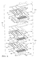
- FIG. 2 is an isometric exploded view of an MEA and bipolar plate in a fuel cell stack
- FIG. 12 is a cross section taken along line XII—XII of FIG. 9 showing the cathode porting
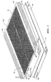
- FIG. 1 schematically depicts a partial PEM fuel cell stack having a pair of membrane-electrode-assemblies (MEAs) 8 and 10 separated from each other by a non-porous, electrically-conductive bipolar plate 12 .
- MEAs membrane-electrode-assemblies
- Each of the MEAs 8 , 10 have a cathode face 8 c , 10 c and an anode face 8 a , 10 a .
- the MEAs 8 and 10 , and bipolar plate 12 are stacked together between non-porous, electrically-conductive, liquid-cooled bipolar plates 14 and 16 .
- the interdigitated flow channels 56 i are divided into a first interdigitated flow path 88 having a plurality of medial legs 90 in fluid communication with the inlet feed 84 and a plurality of medial legs 92 in fluid communication with exhaust feed 86 which traverse the first half of the bipolar plate and a second interdigitated flow path 94 having a plurality of medial legs 96 in fluid communication with the inlet feed 84 and a plurality of medial legs 98 in fluid communication with exhaust feed 86 which traverse the second half of the bipolar plate 12 .
- Reactant gas flowing in the interdigitated flow paths 88 , 94 from inlet feed 84 must cross over land 54 i through the primary current collector 40 to be discharged through exhaust feed 86 , as best seen in FIG. 7 .
- Coolant flows through supply header aperture 132 along fluid communication path 166 defined by bipolar plate 110 , seals 112 , 116 and bipolar plate 118 through coolant port 138 and then along fluid communication path 168 defined by bipolar plate 118 , spacer 120 and bipolar plate 122 into an interior coolant volume 170 defined between the flow fields formed on the bipolar plate 118 and bipolar plate 122 .
Abstract
Description
Claims (20)
Priority Applications (8)
| Application Number | Priority Date | Filing Date | Title |
|---|---|---|---|
| US09/791,528 US6503653B2 (en) | 2001-02-23 | 2001-02-23 | Stamped bipolar plate for PEM fuel cell stack |
| EP02001274A EP1235289A3 (en) | 2001-02-23 | 2002-01-17 | Stamped bipolar plate for PEM fuel cell stack |
| JP2002041288A JP3911172B2 (en) | 2001-02-23 | 2002-02-19 | Perforated bipolar plate for PEM fuel cell stack |
| JP2002568444A JP3754673B2 (en) | 2001-02-23 | 2002-02-22 | Embossed bipolar plate for PEM fuel cell stack |
| EP02724986A EP1380062A1 (en) | 2001-02-23 | 2002-02-22 | Stamped bipolar plate for pem fuel cell stack |
| CNA02805427XA CN1493092A (en) | 2001-02-23 | 2002-02-22 | Stamped bipolar plate for PEM fuel stack |
| PCT/US2002/005326 WO2002069425A1 (en) | 2001-02-23 | 2002-02-22 | Stamped bipolar plate for pem fuel cell stack |
| US10/322,092 US6893770B2 (en) | 2001-02-23 | 2002-12-17 | Stamped bipolar plate for PEM fuel cell stack |
Applications Claiming Priority (1)
| Application Number | Priority Date | Filing Date | Title |
|---|---|---|---|
| US09/791,528 US6503653B2 (en) | 2001-02-23 | 2001-02-23 | Stamped bipolar plate for PEM fuel cell stack |
Related Child Applications (1)
| Application Number | Title | Priority Date | Filing Date |
|---|---|---|---|
| US10/322,092 Continuation US6893770B2 (en) | 2001-02-23 | 2002-12-17 | Stamped bipolar plate for PEM fuel cell stack |
Publications (2)
| Publication Number | Publication Date |
|---|---|
| US20020119358A1 US20020119358A1 (en) | 2002-08-29 |
| US6503653B2 true US6503653B2 (en) | 2003-01-07 |
Family
ID=25154021
Family Applications (2)
| Application Number | Title | Priority Date | Filing Date |
|---|---|---|---|
| US09/791,528 Expired - Lifetime US6503653B2 (en) | 2001-02-23 | 2001-02-23 | Stamped bipolar plate for PEM fuel cell stack |
| US10/322,092 Expired - Lifetime US6893770B2 (en) | 2001-02-23 | 2002-12-17 | Stamped bipolar plate for PEM fuel cell stack |
Family Applications After (1)
| Application Number | Title | Priority Date | Filing Date |
|---|---|---|---|
| US10/322,092 Expired - Lifetime US6893770B2 (en) | 2001-02-23 | 2002-12-17 | Stamped bipolar plate for PEM fuel cell stack |
Country Status (5)
| Country | Link |
|---|---|
| US (2) | US6503653B2 (en) |
| EP (2) | EP1235289A3 (en) |
| JP (2) | JP3911172B2 (en) |
| CN (1) | CN1493092A (en) |
| WO (1) | WO2002069425A1 (en) |
Cited By (60)
| Publication number | Priority date | Publication date | Assignee | Title |
|---|---|---|---|---|
| US20030059662A1 (en) * | 2001-09-17 | 2003-03-27 | 3M Innovative Properties Company | Flow field |
| US20030124405A1 (en) * | 2001-02-23 | 2003-07-03 | Rock Jeffrey A. | Stamped bipolar plate for PEM fuel cell stack |
| US20030129468A1 (en) * | 2002-01-04 | 2003-07-10 | Honeywell International, Inc. | Gas block mechanism for water removal in fuel cells |
| US6677071B2 (en) * | 2001-02-15 | 2004-01-13 | Asia Pacific Fuel Cell Technologies, Ltd. | Bipolar plate for a fuel cell |
| US20040142224A1 (en) * | 2003-01-21 | 2004-07-22 | Abd Elhamid Mahmoud H. | Joining of bipolar plates in proton exchange membrane fuel cell stacks |
| US20040175608A1 (en) * | 2003-03-07 | 2004-09-09 | Lisi Daniel J. | Polymeric separator plates |
| US20040209150A1 (en) * | 2003-04-18 | 2004-10-21 | Rock Jeffrey A. | Stamped fuel cell bipolar plate |
| US20050048351A1 (en) * | 2001-11-07 | 2005-03-03 | Hood Peter D. | Fuel cell fluid flow field plates |
| US20050053810A1 (en) * | 2003-09-08 | 2005-03-10 | Honda Motor Co., Ltd. | Method and system for starting up fuel cell stack at subzero temperatures, and method of designing fuel cell stack |
| US20050058864A1 (en) * | 2003-09-12 | 2005-03-17 | Goebel Steven G. | Nested bipolar plate for fuel cell and method |
| US20050095494A1 (en) * | 2003-11-03 | 2005-05-05 | Fuss Robert L. | Variable catalyst loading based on flow field geometry |
| US20050100775A1 (en) * | 2003-11-07 | 2005-05-12 | Rock Jeffrey A. | One piece bipolar plate with spring seals |
| US20050133568A1 (en) * | 2003-12-17 | 2005-06-23 | Sigler David R. | Bipolar plate fabrication |
| US20050133575A1 (en) * | 2003-12-17 | 2005-06-23 | Xiaohong Gayden | Bipolar plate fabrication by roll bonding |
| US20050153184A1 (en) * | 2004-01-09 | 2005-07-14 | Beutel Matthew J. | Bipolar plate with cross-linked channels |
| US20050186378A1 (en) * | 2004-02-23 | 2005-08-25 | Bhatt Sanjiv M. | Compositions comprising carbon nanotubes and articles formed therefrom |
| US20050214627A1 (en) * | 2004-03-24 | 2005-09-29 | Honda Motor Co., Ltd. | Fuel cell and fuel cell stack |
| US20060068266A1 (en) * | 2004-09-30 | 2006-03-30 | Proton Energy Systems, Inc. | Electrochemical cell bipolar plate |
| US20060068265A1 (en) * | 2004-09-30 | 2006-03-30 | Proton Energy Systems, Inc. | Electrochemical cell bipolar plate |
| US20060099480A1 (en) * | 2004-11-11 | 2006-05-11 | Henderson David E | Electrochemical cell bipolar plate with sealing feature |
| US20060099479A1 (en) * | 2004-11-11 | 2006-05-11 | Jake Friedman | Electrochemical cell bipolar plate with sealing feature |
| US20060240308A1 (en) * | 2005-04-22 | 2006-10-26 | Volker Formanski | Fuel cell design with an integrated heat exchanger and gas humidification unit |
| US20070031723A1 (en) * | 2005-08-03 | 2007-02-08 | Mikhail Youssef M | Durability for the MEA and bipolar plates in PEM fuel cells using hydrogen peroxide decomposition catalysts |
| US20070154761A1 (en) * | 2006-01-04 | 2007-07-05 | Eun Yeong C | Flat type fuel cell assembly having connector |
| US20070202383A1 (en) * | 2006-02-27 | 2007-08-30 | Goebel Steven G | Balanced hydrogen feed for a fuel cell |
| US20070207368A1 (en) * | 2006-03-03 | 2007-09-06 | Anderson Everett B | Method and apparatus for electrochemical flow field member |
| US20080138687A1 (en) * | 2006-11-22 | 2008-06-12 | Gm Global Technology Operations, Inc. | Inexpensive approach for coating bipolar plates for pem fuel cells |
| US20080199739A1 (en) * | 2007-02-20 | 2008-08-21 | Commonwealth Scientific And Industrial Research Organisation | Electrochemical cell stack and a method of forming a bipolar interconnect for an electrochemical cell stack |
| US20080199738A1 (en) * | 2007-02-16 | 2008-08-21 | Bloom Energy Corporation | Solid oxide fuel cell interconnect |
| US20080199752A1 (en) * | 2007-02-20 | 2008-08-21 | Commonwealth Scientific And Industrial Research Organisation | Electrochemical stack with pressed bipolar plate |
| US20080199751A1 (en) * | 2007-02-20 | 2008-08-21 | Commonwealth Scientific And Industrial Research Organisation | Bipolar plate for an air breathing fuel cell stack |
| US20080268315A1 (en) * | 2007-04-25 | 2008-10-30 | Samsung Sdi Co., Ltd. | Fuel cell stack |
| CN100442582C (en) * | 2005-04-12 | 2008-12-10 | 浙江大学 | Structure of double-swallow-tail shape flow field plate for proton exchange membrane fuel cell |
| US20090004539A1 (en) * | 2007-06-28 | 2009-01-01 | Honda Motor Co., Ltd. | Fuel cell |
| US20090197147A1 (en) * | 2008-01-31 | 2009-08-06 | Fly Gerald W | Metal bead seal for fuel cell plate |
| US7604888B2 (en) | 2004-07-30 | 2009-10-20 | Gm Global Technologies Operations, Inc. | Stamped PEM fuel cell plate manufacturing |
| US7615308B2 (en) | 2004-03-03 | 2009-11-10 | Ird Fuel Cells A/S | Dual function, bipolar separator plates for fuel cells |
| US20100086820A1 (en) * | 2008-10-03 | 2010-04-08 | Gm Global Technology Operations, Inc. | Bipolar plate with features for mitigation of exit water retention |
| US20100119909A1 (en) * | 2008-11-11 | 2010-05-13 | Bloom Energy Corporation | Fuel cell interconnect |
| US20100178580A1 (en) * | 2009-01-13 | 2010-07-15 | Gm Global Technology Operations, Inc. | Bipolar plate for a fuel cell stack |
| US20100261087A1 (en) * | 2009-04-09 | 2010-10-14 | Ford Motor Company | Fuel cell having perforated flow field |
| US20100267883A1 (en) * | 2006-02-22 | 2010-10-21 | Bhatt Sanjiv M | Nanotube Polymer Composite Composition and Methods of Making |
| US20120270137A1 (en) * | 2011-04-22 | 2012-10-25 | Honda Motor Co., Ltd. | Fuel cell |
| US8486575B2 (en) | 2004-02-05 | 2013-07-16 | GM Global Technology Operations LLC | Passive hydrogen vent for a fuel cell |
| US8962219B2 (en) | 2011-11-18 | 2015-02-24 | Bloom Energy Corporation | Fuel cell interconnects and methods of fabrication |
| US8968904B2 (en) | 2010-04-05 | 2015-03-03 | GM Global Technology Operations LLC | Secondary battery module |
| US9368810B2 (en) | 2012-11-06 | 2016-06-14 | Bloom Energy Corporation | Interconnect and end plate design for fuel cell stack |
| US9478812B1 (en) | 2012-10-17 | 2016-10-25 | Bloom Energy Corporation | Interconnect for fuel cell stack |
| US9502721B2 (en) | 2013-10-01 | 2016-11-22 | Bloom Energy Corporation | Pre-formed powder delivery to powder press machine |
| DE102016224247A1 (en) * | 2016-12-06 | 2018-06-07 | Bayerische Motoren Werke Aktiengesellschaft | fuel cell stack |
| US9993874B2 (en) | 2014-02-25 | 2018-06-12 | Bloom Energy Corporation | Composition and processing of metallic interconnects for SOFC stacks |
| US10211477B2 (en) | 2016-08-10 | 2019-02-19 | GM Global Technology Operations LLC | Fuel cell stack assembly |
| US10258932B2 (en) | 2014-03-11 | 2019-04-16 | Uti Limited Partnership | Porous carbon films |
| US10355331B2 (en) | 2015-06-04 | 2019-07-16 | Dana Canada Corporation | Heat exchanger with regional flow distribution for uniform cooling of battery cells |
| US10601054B2 (en) | 2018-07-14 | 2020-03-24 | Amir Hossein Zare | Fuel cell with impingement jet flow field |
| US10665871B2 (en) * | 2015-11-16 | 2020-05-26 | Volkswagen Ag | Fuel cell stack having bipolar plates, and fuel cell system |
| US10964956B2 (en) | 2018-06-06 | 2021-03-30 | GM Global Technology Operations LLC | Fuel cell stack assembly |
| US11289728B2 (en) | 2017-09-01 | 2022-03-29 | Stryten Critical E-Storage Llc | Segmented frames for redox flow batteries |
| US11371782B2 (en) * | 2018-07-26 | 2022-06-28 | Dana Canada Corporation | Heat exchanger with parallel flow features to enhance heat conduction |
| US11710843B2 (en) | 2020-05-15 | 2023-07-25 | Ess Tech, Inc. | Redox flow battery and battery system |
Families Citing this family (56)
| Publication number | Priority date | Publication date | Assignee | Title |
|---|---|---|---|---|
| DE10100757A1 (en) * | 2001-01-10 | 2002-08-01 | Daimler Chrysler Ag | Electrochemical fuel cell stack |
| JP4121340B2 (en) * | 2002-09-04 | 2008-07-23 | 本田技研工業株式会社 | Fuel cell |
| FR2846798A1 (en) * | 2002-11-05 | 2004-05-07 | Helion | Bipolar plate for fuel cells used in vehicle electrics, especially urban buses and trams, but also for fixed installations such as hospitals, has two metallic plates with silicone sealing joints between them |
| FR2858116B1 (en) * | 2003-07-24 | 2005-11-11 | Peugeot Citroen Automobiles Sa | BATTERY CELL COMPRISING A REACTIVE GAS DISTRIBUTION SYSTEM |
| FR2858466A1 (en) * | 2003-07-28 | 2005-02-04 | Renault Sa | Bipolar plate for ion-exchange membrane type fuel cell, has circulation channels with inlet and outlet sections parallely circulating and spirally arranged, where inlet section opens directly into outlet section to form continuous channel |
| JP4620361B2 (en) * | 2004-02-13 | 2011-01-26 | Fco株式会社 | Fuel cell |
| DE102004016318A1 (en) * | 2004-03-30 | 2005-10-20 | Reinz Dichtungs Gmbh | Bipolar plate and method for their preparation and a bipolar plate-containing electrochemical system |
| JP4634737B2 (en) * | 2004-04-28 | 2011-02-16 | 本田技研工業株式会社 | Fuel cell stack |
| JP4792213B2 (en) * | 2004-07-29 | 2011-10-12 | 東海ゴム工業株式会社 | Separator for polymer electrolyte fuel cell and cell for polymer electrolyte fuel cell using the same |
| US7951507B2 (en) * | 2004-08-26 | 2011-05-31 | GM Global Technology Operations LLC | Fluid flow path for stamped bipolar plate |
| US7686937B2 (en) * | 2004-09-28 | 2010-03-30 | Honda Motor Co., Ltd. | Separator plates, ion pumps, and hydrogen fuel infrastructure systems and methods for generating hydrogen |
| TWM266557U (en) * | 2004-10-26 | 2005-06-01 | Antig Tech Co Ltd | Fuel cell device with dual-sided channel plate |
| KR100647666B1 (en) * | 2004-11-29 | 2006-11-23 | 삼성에스디아이 주식회사 | Bipolar plate and direct liquid feed fuel cell stack |
| JP4951925B2 (en) * | 2005-10-11 | 2012-06-13 | トヨタ自動車株式会社 | Gas separator for fuel cell and fuel cell |
| JP4908912B2 (en) * | 2006-04-28 | 2012-04-04 | 本田技研工業株式会社 | Fuel cell stack |
| CN100416900C (en) * | 2006-04-29 | 2008-09-03 | 中山大学 | Proton exchange membrane fuel cell plate comprising combined flow channel |
| US9172106B2 (en) * | 2006-11-09 | 2015-10-27 | GM Global Technology Operations LLC | Fuel cell microporous layer with microchannels |
| JP5046615B2 (en) * | 2006-11-09 | 2012-10-10 | 本田技研工業株式会社 | Fuel cell |
| KR100862419B1 (en) * | 2006-12-05 | 2008-10-08 | 현대자동차주식회사 | Separating plate for fuel cell |
| KR101408885B1 (en) * | 2007-06-15 | 2014-06-19 | 삼성에스디아이 주식회사 | Fuel composition for polymer electrolyte fuel cell polymer electrolyte fuel cell system comprising same |
| US7851105B2 (en) | 2007-06-18 | 2010-12-14 | Daimler Ag | Electrochemical fuel cell stack having staggered fuel and oxidant plenums |
| EP2201631B1 (en) * | 2007-08-20 | 2015-05-27 | myFC AB | An arrangement for interconnecting electrochemical cells, a fuel cell assembly and method of manufacturing a fuel cell device |
| US8394547B2 (en) | 2007-09-07 | 2013-03-12 | GM Global Technology Operations LLC | Fuel cell bipolar plate exit for improved flow distribution and freeze compatibility |
| EP2072039A1 (en) * | 2007-12-21 | 2009-06-24 | Merz Pharma GmbH & Co.KGaA | Use of a neurotoxic component of Clostridium botulinum toxin complex to reduce or prevent side effects |
| WO2010003439A1 (en) * | 2008-07-11 | 2010-01-14 | Daimler Ag | Electrochemical fuel cell stack having staggered fuel and oxidant plenums |
| JP2010086696A (en) * | 2008-09-30 | 2010-04-15 | Hitachi Ltd | Fuel cell separator |
| US8129075B2 (en) * | 2008-10-16 | 2012-03-06 | GM Global Technology Operations LLC | Bipolar plate header formed features |
| US8916313B2 (en) * | 2009-07-16 | 2014-12-23 | Ford Motor Company | Fuel cell |
| US20110014537A1 (en) * | 2009-07-16 | 2011-01-20 | Ford Motor Company | Fuel cell |
| US8470489B2 (en) | 2010-05-13 | 2013-06-25 | Energyor Technologies Inc. | Method for producing bipolar plates |
| EP3266814B1 (en) | 2011-10-27 | 2019-05-15 | Garmor Inc. | Method for preparing a composite comprising graphene structures and the composite |
| TWI499120B (en) * | 2012-03-22 | 2015-09-01 | Univ Nat Cheng Kung | Proton exchange membrane fuel cell |
| US10122025B2 (en) | 2012-08-24 | 2018-11-06 | Ford Global Technologies, Llc | Proton exchange membrane fuel cell with stepped channel bipolar plate |
| US9786928B2 (en) * | 2012-08-24 | 2017-10-10 | Ford Global Technologies, Llc | Proton exchange membrane fuel cell with stepped channel bipolar plate |
| KR101939968B1 (en) | 2013-03-08 | 2019-01-18 | 갈모어 인코포레이티드 | Graphene entrainment in a host |
| WO2014138596A1 (en) | 2013-03-08 | 2014-09-12 | Garmor, Inc. | Large scale oxidized graphene production for industrial applications |
| CN104051771B (en) * | 2013-03-15 | 2018-11-02 | 福特全球技术公司 | Fuel cell pack and vehicle including it |
| TWI506845B (en) * | 2013-07-23 | 2015-11-01 | Gunitech Corp | Water treatment device for fuel cell pack |
| CN103700865B (en) * | 2013-12-18 | 2015-12-09 | 清华大学 | A kind of metal double polar plates for fuel cell |
| US9705139B2 (en) * | 2014-07-30 | 2017-07-11 | GM Global Technology Operations LLC | Printed multi-function seals for fuel cells |
| US9828290B2 (en) | 2014-08-18 | 2017-11-28 | Garmor Inc. | Graphite oxide entrainment in cement and asphalt composite |
| WO2016154057A1 (en) | 2015-03-23 | 2016-09-29 | Garmor Inc. | Engineered composite structure using graphene oxide |
| EP3283448B1 (en) | 2015-04-13 | 2022-06-01 | Asbury Graphite of North Carolina, Inc. | Graphite oxide reinforced fiber in hosts such as concrete or asphalt |
| WO2016200469A1 (en) | 2015-06-09 | 2016-12-15 | Garmor Inc. | Graphite oxide and polyacrylonitrile based composite |
| WO2017009767A1 (en) * | 2015-07-10 | 2017-01-19 | Tata Chemicals Limited | A bipolar plate for fuel cells |
| WO2017053204A1 (en) * | 2015-09-21 | 2017-03-30 | Garmor Inc. | Low-cost, high-performance composite bipolar plate |
| KR102169179B1 (en) * | 2016-03-31 | 2020-10-21 | 주식회사 엘지화학 | Bipolar plate and redox flow cell battery comprising the same |
| WO2017180759A1 (en) * | 2016-04-12 | 2017-10-19 | Garmor Inc. | Engineered low-cost, high-performance conductive composite |
| CA3041315C (en) | 2016-10-26 | 2021-06-01 | Garmor Inc. | Additive coated particles for low cost high performance materials |
| US20180313787A1 (en) * | 2017-04-28 | 2018-11-01 | BioForce Medical, Inc. | Isolation of Circulating Tumor Cells Using Electric Fields |
| US10468707B2 (en) * | 2017-05-04 | 2019-11-05 | Gm Global Technology Operations Llc. | Fuel cell stack assembly |
| EP3804012A4 (en) | 2018-05-31 | 2022-03-30 | Bloom Energy Corporation | Cross-flow interconnect and fuel cell system including same |
| US11791061B2 (en) | 2019-09-12 | 2023-10-17 | Asbury Graphite North Carolina, Inc. | Conductive high strength extrudable ultra high molecular weight polymer graphene oxide composite |
| CN111554950B (en) * | 2020-05-18 | 2021-07-09 | 浙江锋源氢能科技有限公司 | Bipolar plate, fuel cell unit, fuel cell and manufacturing method thereof |
| US20230327146A1 (en) * | 2022-04-06 | 2023-10-12 | Hydrogenics Corporation | Single sheet bipolar plate for cell stack assembly and method of making and using the same |
| CN117096370B (en) * | 2023-10-17 | 2024-01-09 | 江苏恒安储能科技有限公司 | Novel flow battery terminal electrode and flow battery assembled by same |
Citations (25)
| Publication number | Priority date | Publication date | Assignee | Title |
|---|---|---|---|---|
| US4344832A (en) | 1979-07-03 | 1982-08-17 | Licentia Patent-Verwaltungs-G.M.B.H. | Electrode system for a fuel or electrolysis cell arrangement |
| US4769297A (en) | 1987-11-16 | 1988-09-06 | International Fuel Cells Corporation | Solid polymer electrolyte fuel cell stack water management system |
| US5108849A (en) | 1989-08-30 | 1992-04-28 | Her Majesty The Queen In Right Of Canada, As Represented By The Minister Of National Defence In Her Britannic Majesty's Government Of The United Kingdom Of Great Britain And Northern Ireland | Fuel cell fluid flow field plate |
| US5230966A (en) | 1991-09-26 | 1993-07-27 | Ballard Power Systems Inc. | Coolant flow field plate for electrochemical fuel cells |
| US5252410A (en) | 1991-09-13 | 1993-10-12 | Ballard Power Systems Inc. | Lightweight fuel cell membrane electrode assembly with integral reactant flow passages |
| US5264299A (en) | 1991-12-26 | 1993-11-23 | International Fuel Cells Corporation | Proton exchange membrane fuel cell support plate and an assembly including the same |
| US5300370A (en) | 1992-11-13 | 1994-04-05 | Ballard Power Systems Inc. | Laminated fluid flow field assembly for electrochemical fuel cells |
| US5482680A (en) | 1992-10-09 | 1996-01-09 | Ballard Power Systems, Inc. | Electrochemical fuel cell assembly with integral selective oxidizer |
| US5521018A (en) | 1993-12-10 | 1996-05-28 | Ballard Power Systems Inc. | Embossed fluid flow field plate for electrochemical fuel cells |
| US5547776A (en) | 1991-01-15 | 1996-08-20 | Ballard Power Systems Inc. | Electrochemical fuel cell stack with concurrently flowing coolant and oxidant streams |
| US5641586A (en) | 1995-12-06 | 1997-06-24 | The Regents Of The University Of California Office Of Technology Transfer | Fuel cell with interdigitated porous flow-field |
| US5773160A (en) | 1994-06-24 | 1998-06-30 | Ballard Power Systems Inc. | Electrochemical fuel cell stack with concurrent flow of coolant and oxidant streams and countercurrent flow of fuel and oxidant streams |
| US5776624A (en) | 1996-12-23 | 1998-07-07 | General Motors Corporation | Brazed bipolar plates for PEM fuel cells |
| US5804326A (en) | 1996-12-20 | 1998-09-08 | Ballard Power Systems Inc. | Integrated reactant and coolant fluid flow field layer for an electrochemical fuel cell |
| US5846668A (en) * | 1996-03-07 | 1998-12-08 | Tanaka Kikinzoku Kogyo K. K. | Fuel cell, electrolytic cell and process of cooling and/or dehumidifying same |
| US5874182A (en) | 1995-12-18 | 1999-02-23 | Ballard Power Systems Inc. | Method and apparatus for reducing reactant crossover in a liquid feed electrochemical fuel cell |
| US5928807A (en) | 1995-11-15 | 1999-07-27 | Ballard Power Systems Inc. | Integrated seal for a PEM fuel cell |
| US5945232A (en) | 1998-04-03 | 1999-08-31 | Plug Power, L.L.C. | PEM-type fuel cell assembly having multiple parallel fuel cell sub-stacks employing shared fluid plate assemblies and shared membrane electrode assemblies |
| US5981098A (en) | 1997-08-28 | 1999-11-09 | Plug Power, L.L.C. | Fluid flow plate for decreased density of fuel cell assembly |
| US6054228A (en) | 1996-06-06 | 2000-04-25 | Lynntech, Inc. | Fuel cell system for low pressure operation |
| US6099984A (en) | 1997-12-15 | 2000-08-08 | General Motors Corporation | Mirrored serpentine flow channels for fuel cell |
| US6159629A (en) | 1998-12-17 | 2000-12-12 | Ballard Power Systems Inc. | Volume effecient layered manifold assembly for electrochemical fuel cell stacks |
| US6174616B1 (en) | 1998-10-07 | 2001-01-16 | Plug Power Inc. | Fuel cell assembly unit for promoting fluid service and design flexibility |
| US6309773B1 (en) | 1999-12-13 | 2001-10-30 | General Motors Corporation | Serially-linked serpentine flow channels for PEM fuel cell |
| US6358642B1 (en) | 1999-12-02 | 2002-03-19 | General Motors Corporation | Flow channels for fuel cell |
Family Cites Families (5)
| Publication number | Priority date | Publication date | Assignee | Title |
|---|---|---|---|---|
| US5362578A (en) * | 1992-12-08 | 1994-11-08 | Institute Of Gas Technology | Integrated main rail, feed rail, and current collector |
| US6207312B1 (en) * | 1998-09-18 | 2001-03-27 | Energy Partners, L.C. | Self-humidifying fuel cell |
| JP4542640B2 (en) * | 1999-02-23 | 2010-09-15 | 本田技研工業株式会社 | Fuel cell stack |
| US6322919B1 (en) * | 1999-08-16 | 2001-11-27 | Alliedsignal Inc. | Fuel cell and bipolar plate for use with same |
| US6503653B2 (en) * | 2001-02-23 | 2003-01-07 | General Motors Corporation | Stamped bipolar plate for PEM fuel cell stack |
-
2001
- 2001-02-23 US US09/791,528 patent/US6503653B2/en not_active Expired - Lifetime
-
2002
- 2002-01-17 EP EP02001274A patent/EP1235289A3/en not_active Withdrawn
- 2002-02-19 JP JP2002041288A patent/JP3911172B2/en not_active Expired - Fee Related
- 2002-02-22 CN CNA02805427XA patent/CN1493092A/en active Pending
- 2002-02-22 EP EP02724986A patent/EP1380062A1/en not_active Withdrawn
- 2002-02-22 JP JP2002568444A patent/JP3754673B2/en not_active Expired - Fee Related
- 2002-02-22 WO PCT/US2002/005326 patent/WO2002069425A1/en active Application Filing
- 2002-12-17 US US10/322,092 patent/US6893770B2/en not_active Expired - Lifetime
Patent Citations (25)
| Publication number | Priority date | Publication date | Assignee | Title |
|---|---|---|---|---|
| US4344832A (en) | 1979-07-03 | 1982-08-17 | Licentia Patent-Verwaltungs-G.M.B.H. | Electrode system for a fuel or electrolysis cell arrangement |
| US4769297A (en) | 1987-11-16 | 1988-09-06 | International Fuel Cells Corporation | Solid polymer electrolyte fuel cell stack water management system |
| US5108849A (en) | 1989-08-30 | 1992-04-28 | Her Majesty The Queen In Right Of Canada, As Represented By The Minister Of National Defence In Her Britannic Majesty's Government Of The United Kingdom Of Great Britain And Northern Ireland | Fuel cell fluid flow field plate |
| US5547776A (en) | 1991-01-15 | 1996-08-20 | Ballard Power Systems Inc. | Electrochemical fuel cell stack with concurrently flowing coolant and oxidant streams |
| US5252410A (en) | 1991-09-13 | 1993-10-12 | Ballard Power Systems Inc. | Lightweight fuel cell membrane electrode assembly with integral reactant flow passages |
| US5230966A (en) | 1991-09-26 | 1993-07-27 | Ballard Power Systems Inc. | Coolant flow field plate for electrochemical fuel cells |
| US5264299A (en) | 1991-12-26 | 1993-11-23 | International Fuel Cells Corporation | Proton exchange membrane fuel cell support plate and an assembly including the same |
| US5482680A (en) | 1992-10-09 | 1996-01-09 | Ballard Power Systems, Inc. | Electrochemical fuel cell assembly with integral selective oxidizer |
| US5300370A (en) | 1992-11-13 | 1994-04-05 | Ballard Power Systems Inc. | Laminated fluid flow field assembly for electrochemical fuel cells |
| US5521018A (en) | 1993-12-10 | 1996-05-28 | Ballard Power Systems Inc. | Embossed fluid flow field plate for electrochemical fuel cells |
| US5773160A (en) | 1994-06-24 | 1998-06-30 | Ballard Power Systems Inc. | Electrochemical fuel cell stack with concurrent flow of coolant and oxidant streams and countercurrent flow of fuel and oxidant streams |
| US5928807A (en) | 1995-11-15 | 1999-07-27 | Ballard Power Systems Inc. | Integrated seal for a PEM fuel cell |
| US5641586A (en) | 1995-12-06 | 1997-06-24 | The Regents Of The University Of California Office Of Technology Transfer | Fuel cell with interdigitated porous flow-field |
| US5874182A (en) | 1995-12-18 | 1999-02-23 | Ballard Power Systems Inc. | Method and apparatus for reducing reactant crossover in a liquid feed electrochemical fuel cell |
| US5846668A (en) * | 1996-03-07 | 1998-12-08 | Tanaka Kikinzoku Kogyo K. K. | Fuel cell, electrolytic cell and process of cooling and/or dehumidifying same |
| US6054228A (en) | 1996-06-06 | 2000-04-25 | Lynntech, Inc. | Fuel cell system for low pressure operation |
| US5804326A (en) | 1996-12-20 | 1998-09-08 | Ballard Power Systems Inc. | Integrated reactant and coolant fluid flow field layer for an electrochemical fuel cell |
| US5776624A (en) | 1996-12-23 | 1998-07-07 | General Motors Corporation | Brazed bipolar plates for PEM fuel cells |
| US5981098A (en) | 1997-08-28 | 1999-11-09 | Plug Power, L.L.C. | Fluid flow plate for decreased density of fuel cell assembly |
| US6099984A (en) | 1997-12-15 | 2000-08-08 | General Motors Corporation | Mirrored serpentine flow channels for fuel cell |
| US5945232A (en) | 1998-04-03 | 1999-08-31 | Plug Power, L.L.C. | PEM-type fuel cell assembly having multiple parallel fuel cell sub-stacks employing shared fluid plate assemblies and shared membrane electrode assemblies |
| US6174616B1 (en) | 1998-10-07 | 2001-01-16 | Plug Power Inc. | Fuel cell assembly unit for promoting fluid service and design flexibility |
| US6159629A (en) | 1998-12-17 | 2000-12-12 | Ballard Power Systems Inc. | Volume effecient layered manifold assembly for electrochemical fuel cell stacks |
| US6358642B1 (en) | 1999-12-02 | 2002-03-19 | General Motors Corporation | Flow channels for fuel cell |
| US6309773B1 (en) | 1999-12-13 | 2001-10-30 | General Motors Corporation | Serially-linked serpentine flow channels for PEM fuel cell |
Non-Patent Citations (2)
| Title |
|---|
| PCT Publication No. WO/0017952, published Mar. 30, 2000. |
| PCT Publication No. WO/94/09519, published Apr. 28, 1994. |
Cited By (111)
| Publication number | Priority date | Publication date | Assignee | Title |
|---|---|---|---|---|
| US6677071B2 (en) * | 2001-02-15 | 2004-01-13 | Asia Pacific Fuel Cell Technologies, Ltd. | Bipolar plate for a fuel cell |
| US20030124405A1 (en) * | 2001-02-23 | 2003-07-03 | Rock Jeffrey A. | Stamped bipolar plate for PEM fuel cell stack |
| US6893770B2 (en) * | 2001-02-23 | 2005-05-17 | General Motors Corporation | Stamped bipolar plate for PEM fuel cell stack |
| US20030059662A1 (en) * | 2001-09-17 | 2003-03-27 | 3M Innovative Properties Company | Flow field |
| US6780536B2 (en) * | 2001-09-17 | 2004-08-24 | 3M Innovative Properties Company | Flow field |
| US20050048351A1 (en) * | 2001-11-07 | 2005-03-03 | Hood Peter D. | Fuel cell fluid flow field plates |
| US8304139B2 (en) | 2001-11-07 | 2012-11-06 | Intelligent Energy Limited | Fuel cell fluid flow field plates |
| US6686084B2 (en) * | 2002-01-04 | 2004-02-03 | Hybrid Power Generation Systems, Llc | Gas block mechanism for water removal in fuel cells |
| US20030129468A1 (en) * | 2002-01-04 | 2003-07-10 | Honeywell International, Inc. | Gas block mechanism for water removal in fuel cells |
| US20040142224A1 (en) * | 2003-01-21 | 2004-07-22 | Abd Elhamid Mahmoud H. | Joining of bipolar plates in proton exchange membrane fuel cell stacks |
| US6887610B2 (en) | 2003-01-21 | 2005-05-03 | General Motors Corporation | Joining of bipolar plates in proton exchange membrane fuel cell stacks |
| US20040175608A1 (en) * | 2003-03-07 | 2004-09-09 | Lisi Daniel J. | Polymeric separator plates |
| US7195836B2 (en) | 2003-03-07 | 2007-03-27 | General Motors Corporation | Polymeric separator plates |
| US20040209150A1 (en) * | 2003-04-18 | 2004-10-21 | Rock Jeffrey A. | Stamped fuel cell bipolar plate |
| WO2004100297A1 (en) * | 2003-04-18 | 2004-11-18 | General Motors Corporation | Stamped fuel cell bipolar plate |
| US7781087B2 (en) | 2003-04-18 | 2010-08-24 | Gm Global Technology Operations, Inc. | Stamped fuel cell bipolar plate |
| DE10394231B4 (en) * | 2003-04-18 | 2009-08-06 | General Motors Corp. (N.D.Ges.D. Staates Delaware), Detroit | Embossed bipolar plate and separator for fuel cells |
| US7459227B2 (en) | 2003-04-18 | 2008-12-02 | General Motors Corporation | Stamped fuel cell bipolar plate |
| US20090004522A1 (en) * | 2003-04-18 | 2009-01-01 | General Motors Corporation | Stamped fuel cell bipolar plate |
| US20050053810A1 (en) * | 2003-09-08 | 2005-03-10 | Honda Motor Co., Ltd. | Method and system for starting up fuel cell stack at subzero temperatures, and method of designing fuel cell stack |
| US7572529B2 (en) * | 2003-09-08 | 2009-08-11 | Honda Motor Co., Ltd. | Method and system for starting up fuel cell stack at subzero temperatures, and method of designing fuel cell stack |
| US20050058864A1 (en) * | 2003-09-12 | 2005-03-17 | Goebel Steven G. | Nested bipolar plate for fuel cell and method |
| US6974648B2 (en) | 2003-09-12 | 2005-12-13 | General Motors Corporation | Nested bipolar plate for fuel cell and method |
| US20060029840A1 (en) * | 2003-09-12 | 2006-02-09 | General Motors Corporation | Nested bipolar plate for fuel cell and method |
| US7601452B2 (en) | 2003-09-12 | 2009-10-13 | Gm Global Technology Operations, Inc. | Nested bipolar plate for fuel cell and method |
| US20050095494A1 (en) * | 2003-11-03 | 2005-05-05 | Fuss Robert L. | Variable catalyst loading based on flow field geometry |
| WO2005048374A2 (en) * | 2003-11-07 | 2005-05-26 | General Motors Corporation | One piece bipolar plate with spring seals |
| DE112004002108B4 (en) * | 2003-11-07 | 2013-03-07 | General Motors Corp. (N.D.Ges.D. Staates Delaware) | PEM fuel cell, seal assembly and method of making the gasket |
| US20050100775A1 (en) * | 2003-11-07 | 2005-05-12 | Rock Jeffrey A. | One piece bipolar plate with spring seals |
| US7186476B2 (en) * | 2003-11-07 | 2007-03-06 | General Motors Corporation | One piece bipolar plate with spring seals |
| WO2005048374A3 (en) * | 2003-11-07 | 2006-05-11 | Gen Motors Corp | One piece bipolar plate with spring seals |
| US7258263B2 (en) | 2003-12-17 | 2007-08-21 | General Motors Corporation | Bipolar plate fabrication |
| US20050133568A1 (en) * | 2003-12-17 | 2005-06-23 | Sigler David R. | Bipolar plate fabrication |
| US20050133575A1 (en) * | 2003-12-17 | 2005-06-23 | Xiaohong Gayden | Bipolar plate fabrication by roll bonding |
| US7252218B2 (en) | 2003-12-17 | 2007-08-07 | General Motors Corporation | Bipolar plate fabrication by roll bonding |
| DE112004002605B4 (en) * | 2004-01-09 | 2014-09-25 | General Motors Corp. (N.D.Ges.D. Staates Delaware) | Bipolar plate with networked channels and fuel cell stack |
| WO2005069406A3 (en) * | 2004-01-09 | 2005-09-15 | Gen Motors Corp | Bipolar plate with cross-linked channels |
| US20050153184A1 (en) * | 2004-01-09 | 2005-07-14 | Beutel Matthew J. | Bipolar plate with cross-linked channels |
| US7781122B2 (en) | 2004-01-09 | 2010-08-24 | Gm Global Technology Operations, Inc. | Bipolar plate with cross-linked channels |
| WO2005069406A2 (en) * | 2004-01-09 | 2005-07-28 | General Motors Corporation | Bipolar plate with cross-linked channels |
| US8486575B2 (en) | 2004-02-05 | 2013-07-16 | GM Global Technology Operations LLC | Passive hydrogen vent for a fuel cell |
| US20050186378A1 (en) * | 2004-02-23 | 2005-08-25 | Bhatt Sanjiv M. | Compositions comprising carbon nanotubes and articles formed therefrom |
| US7615308B2 (en) | 2004-03-03 | 2009-11-10 | Ird Fuel Cells A/S | Dual function, bipolar separator plates for fuel cells |
| US20050214627A1 (en) * | 2004-03-24 | 2005-09-29 | Honda Motor Co., Ltd. | Fuel cell and fuel cell stack |
| US8153288B2 (en) | 2004-03-24 | 2012-04-10 | Honda Motor Co., Ltd. | Fuel cell and fuel cell stack |
| US7604888B2 (en) | 2004-07-30 | 2009-10-20 | Gm Global Technologies Operations, Inc. | Stamped PEM fuel cell plate manufacturing |
| US20060068265A1 (en) * | 2004-09-30 | 2006-03-30 | Proton Energy Systems, Inc. | Electrochemical cell bipolar plate |
| US7402358B2 (en) | 2004-09-30 | 2008-07-22 | Proton Energy Systems, Inc. | Electrochemical cell bipolar plate |
| US7378177B2 (en) | 2004-09-30 | 2008-05-27 | Proton Energy Systems, Inc. | Electrochemical cell bipolar plate |
| US20060068266A1 (en) * | 2004-09-30 | 2006-03-30 | Proton Energy Systems, Inc. | Electrochemical cell bipolar plate |
| US7452623B2 (en) | 2004-11-11 | 2008-11-18 | Proton Energy Systems, Inc. | Electrochemical cell bipolar plate with sealing feature |
| US20060099479A1 (en) * | 2004-11-11 | 2006-05-11 | Jake Friedman | Electrochemical cell bipolar plate with sealing feature |
| US20060099480A1 (en) * | 2004-11-11 | 2006-05-11 | Henderson David E | Electrochemical cell bipolar plate with sealing feature |
| US7491463B2 (en) | 2004-11-11 | 2009-02-17 | Proton Energy Systems, Inc. | Electrochemical cell bipolar plate with sealing feature |
| US8652391B2 (en) | 2005-02-03 | 2014-02-18 | Entegris, Inc. | Method of forming substrate carriers and articles from compositions comprising carbon nanotubes |
| CN100442582C (en) * | 2005-04-12 | 2008-12-10 | 浙江大学 | Structure of double-swallow-tail shape flow field plate for proton exchange membrane fuel cell |
| US8568937B2 (en) | 2005-04-22 | 2013-10-29 | GM Global Technology Operations LLC | Fuel cell design with an integrated heat exchanger and gas humidification unit |
| US7829231B2 (en) | 2005-04-22 | 2010-11-09 | Gm Global Technology Operations, Inc. | Fuel cell design with an integrated heat exchanger and gas humidification unit |
| US20060240308A1 (en) * | 2005-04-22 | 2006-10-26 | Volker Formanski | Fuel cell design with an integrated heat exchanger and gas humidification unit |
| US20100304261A1 (en) * | 2005-04-22 | 2010-12-02 | Gm Global Technology Operations, Inc. | Fuel cell design with an integrated heat exchanger and gas humidification unit |
| US20070031723A1 (en) * | 2005-08-03 | 2007-02-08 | Mikhail Youssef M | Durability for the MEA and bipolar plates in PEM fuel cells using hydrogen peroxide decomposition catalysts |
| US8257883B2 (en) * | 2005-08-03 | 2012-09-04 | GM Global Technology Operations LLC | Durability for the MEA and bipolar plates in PEM fuel cells using hydrogen peroxide decomposition catalysts |
| US20070154761A1 (en) * | 2006-01-04 | 2007-07-05 | Eun Yeong C | Flat type fuel cell assembly having connector |
| US20100267883A1 (en) * | 2006-02-22 | 2010-10-21 | Bhatt Sanjiv M | Nanotube Polymer Composite Composition and Methods of Making |
| US20070202383A1 (en) * | 2006-02-27 | 2007-08-30 | Goebel Steven G | Balanced hydrogen feed for a fuel cell |
| US7935455B2 (en) | 2006-02-27 | 2011-05-03 | GM Global Technology Operations LLC | Balanced hydrogen feed for a fuel cell |
| US20070207368A1 (en) * | 2006-03-03 | 2007-09-06 | Anderson Everett B | Method and apparatus for electrochemical flow field member |
| US8455155B2 (en) | 2006-11-22 | 2013-06-04 | GM Global Technology Operations LLC | Inexpensive approach for coating bipolar plates for PEM fuel cells |
| US20080138687A1 (en) * | 2006-11-22 | 2008-06-12 | Gm Global Technology Operations, Inc. | Inexpensive approach for coating bipolar plates for pem fuel cells |
| US20080199738A1 (en) * | 2007-02-16 | 2008-08-21 | Bloom Energy Corporation | Solid oxide fuel cell interconnect |
| US20080199752A1 (en) * | 2007-02-20 | 2008-08-21 | Commonwealth Scientific And Industrial Research Organisation | Electrochemical stack with pressed bipolar plate |
| US20080199739A1 (en) * | 2007-02-20 | 2008-08-21 | Commonwealth Scientific And Industrial Research Organisation | Electrochemical cell stack and a method of forming a bipolar interconnect for an electrochemical cell stack |
| US20080199751A1 (en) * | 2007-02-20 | 2008-08-21 | Commonwealth Scientific And Industrial Research Organisation | Bipolar plate for an air breathing fuel cell stack |
| US8790843B2 (en) | 2007-04-25 | 2014-07-29 | Samsung Sdi Co., Ltd | Fuel cell stack |
| US20080268315A1 (en) * | 2007-04-25 | 2008-10-30 | Samsung Sdi Co., Ltd. | Fuel cell stack |
| US20090004539A1 (en) * | 2007-06-28 | 2009-01-01 | Honda Motor Co., Ltd. | Fuel cell |
| US8551671B2 (en) | 2007-06-28 | 2013-10-08 | Honda Motor Co., Ltd. | Fuel cell fluid sealing structure |
| US8371587B2 (en) | 2008-01-31 | 2013-02-12 | GM Global Technology Operations LLC | Metal bead seal for fuel cell plate |
| US20090197147A1 (en) * | 2008-01-31 | 2009-08-06 | Fly Gerald W | Metal bead seal for fuel cell plate |
| US9153826B2 (en) * | 2008-10-03 | 2015-10-06 | GM Global Technology Operations LLC | Bipolar plate with features for mitigation of exit water retention |
| US20100086820A1 (en) * | 2008-10-03 | 2010-04-08 | Gm Global Technology Operations, Inc. | Bipolar plate with features for mitigation of exit water retention |
| US9461314B2 (en) | 2008-11-11 | 2016-10-04 | Bloom Energy Corporation | Fuel cell interconnect |
| US20100119909A1 (en) * | 2008-11-11 | 2010-05-13 | Bloom Energy Corporation | Fuel cell interconnect |
| US8986905B2 (en) | 2008-11-11 | 2015-03-24 | Bloom Energy Corporation | Fuel cell interconnect |
| US20100178580A1 (en) * | 2009-01-13 | 2010-07-15 | Gm Global Technology Operations, Inc. | Bipolar plate for a fuel cell stack |
| US8889314B2 (en) * | 2009-01-13 | 2014-11-18 | GM Global Technology Operations LLC | Bipolar plate for a fuel cell stack |
| US9608282B2 (en) | 2009-04-09 | 2017-03-28 | Ford Motor Company | Fuel cell having perforated flow field |
| US20100261087A1 (en) * | 2009-04-09 | 2010-10-14 | Ford Motor Company | Fuel cell having perforated flow field |
| US9178230B2 (en) | 2009-04-09 | 2015-11-03 | Ford Motor Company | Fuel cell having perforated flow field |
| US8968904B2 (en) | 2010-04-05 | 2015-03-03 | GM Global Technology Operations LLC | Secondary battery module |
| US9653747B2 (en) * | 2011-04-22 | 2017-05-16 | Honda Motor Co., Ltd. | Fuel cell with seal cut-outs on the separator in the gas passage |
| US20120270137A1 (en) * | 2011-04-22 | 2012-10-25 | Honda Motor Co., Ltd. | Fuel cell |
| US8962219B2 (en) | 2011-11-18 | 2015-02-24 | Bloom Energy Corporation | Fuel cell interconnects and methods of fabrication |
| US9478812B1 (en) | 2012-10-17 | 2016-10-25 | Bloom Energy Corporation | Interconnect for fuel cell stack |
| US9368809B2 (en) | 2012-11-06 | 2016-06-14 | Bloom Energy Corporation | Interconnect and end plate design for fuel cell stack |
| US9368810B2 (en) | 2012-11-06 | 2016-06-14 | Bloom Energy Corporation | Interconnect and end plate design for fuel cell stack |
| US9673457B2 (en) | 2012-11-06 | 2017-06-06 | Bloom Energy Corporation | Interconnect and end plate design for fuel cell stack |
| US9502721B2 (en) | 2013-10-01 | 2016-11-22 | Bloom Energy Corporation | Pre-formed powder delivery to powder press machine |
| US10593962B2 (en) | 2013-10-01 | 2020-03-17 | Bloom Energy Corporation | Pre-formed powder delivery to powder press machine |
| US9993874B2 (en) | 2014-02-25 | 2018-06-12 | Bloom Energy Corporation | Composition and processing of metallic interconnects for SOFC stacks |
| US10258932B2 (en) | 2014-03-11 | 2019-04-16 | Uti Limited Partnership | Porous carbon films |
| US10355331B2 (en) | 2015-06-04 | 2019-07-16 | Dana Canada Corporation | Heat exchanger with regional flow distribution for uniform cooling of battery cells |
| US10665871B2 (en) * | 2015-11-16 | 2020-05-26 | Volkswagen Ag | Fuel cell stack having bipolar plates, and fuel cell system |
| US10211477B2 (en) | 2016-08-10 | 2019-02-19 | GM Global Technology Operations LLC | Fuel cell stack assembly |
| DE102016224247A1 (en) * | 2016-12-06 | 2018-06-07 | Bayerische Motoren Werke Aktiengesellschaft | fuel cell stack |
| US11289728B2 (en) | 2017-09-01 | 2022-03-29 | Stryten Critical E-Storage Llc | Segmented frames for redox flow batteries |
| US11764384B2 (en) | 2017-09-01 | 2023-09-19 | Stryten Critical E-Storage Llc | Segmented frames for redox flow batteries |
| US10964956B2 (en) | 2018-06-06 | 2021-03-30 | GM Global Technology Operations LLC | Fuel cell stack assembly |
| US10601054B2 (en) | 2018-07-14 | 2020-03-24 | Amir Hossein Zare | Fuel cell with impingement jet flow field |
| US11371782B2 (en) * | 2018-07-26 | 2022-06-28 | Dana Canada Corporation | Heat exchanger with parallel flow features to enhance heat conduction |
| US11710843B2 (en) | 2020-05-15 | 2023-07-25 | Ess Tech, Inc. | Redox flow battery and battery system |
Also Published As
| Publication number | Publication date |
|---|---|
| JP2004522262A (en) | 2004-07-22 |
| US20030124405A1 (en) | 2003-07-03 |
| EP1235289A3 (en) | 2009-05-13 |
| JP2002260690A (en) | 2002-09-13 |
| EP1380062A1 (en) | 2004-01-14 |
| US20020119358A1 (en) | 2002-08-29 |
| CN1493092A (en) | 2004-04-28 |
| EP1235289A2 (en) | 2002-08-28 |
| WO2002069425A1 (en) | 2002-09-06 |
| US6893770B2 (en) | 2005-05-17 |
| JP3754673B2 (en) | 2006-03-15 |
| JP3911172B2 (en) | 2007-05-09 |
Similar Documents
| Publication | Publication Date | Title |
|---|---|---|
| US6503653B2 (en) | Stamped bipolar plate for PEM fuel cell stack | |
| US6358642B1 (en) | Flow channels for fuel cell | |
| US6309773B1 (en) | Serially-linked serpentine flow channels for PEM fuel cell | |
| US6099984A (en) | Mirrored serpentine flow channels for fuel cell | |
| US6699614B2 (en) | Converging/diverging flow channels for fuel cell | |
| US7601452B2 (en) | Nested bipolar plate for fuel cell and method | |
| US7112385B2 (en) | Flow restrictors in fuel cell flow-field | |
| US7459227B2 (en) | Stamped fuel cell bipolar plate | |
| TW466792B (en) | Sheet metal bipolar plate design for polymer electrolyte membrane fuel cells | |
| US8298714B2 (en) | Tunnel bridge with elastomeric seal for a fuel cell stack repeating unit | |
| US20040151971A1 (en) | PEM fuel cell with flow-field having a branched midsection | |
| WO2004070859A1 (en) | Pem fuel cell with flow-field having a branched midsection | |
| WO2004070855A2 (en) | Flow restrictors in fuel cell flow-field | |
| JP2006514405A (en) | Flow restrictor in fuel cell flow field |
Legal Events
| Date | Code | Title | Description |
|---|---|---|---|
| AS | Assignment |
Owner name: GENERAL MOTORS CORPORATION, MICHIGAN Free format text: ASSIGNMENT OF ASSIGNORS INTEREST;ASSIGNOR:ROCK, JEFFREY A.;REEL/FRAME:011580/0827 Effective date: 20010221 |
|
| STCF | Information on status: patent grant |
Free format text: PATENTED CASE |
|
| FPAY | Fee payment |
Year of fee payment: 4 |
|
| AS | Assignment |
Owner name: GM GLOBAL TECHNOLOGY OPERATIONS, INC., MICHIGAN Free format text: ASSIGNMENT OF ASSIGNORS INTEREST;ASSIGNOR:GENERAL MOTORS CORPORATION;REEL/FRAME:022092/0737 Effective date: 20050119 Owner name: GM GLOBAL TECHNOLOGY OPERATIONS, INC.,MICHIGAN Free format text: ASSIGNMENT OF ASSIGNORS INTEREST;ASSIGNOR:GENERAL MOTORS CORPORATION;REEL/FRAME:022092/0737 Effective date: 20050119 |
|
| AS | Assignment |
Owner name: UNITED STATES DEPARTMENT OF THE TREASURY, DISTRICT Free format text: SECURITY AGREEMENT;ASSIGNOR:GM GLOBAL TECHNOLOGY OPERATIONS, INC.;REEL/FRAME:022201/0501 Effective date: 20081231 |
|
| AS | Assignment |
Owner name: CITICORP USA, INC. AS AGENT FOR HEDGE PRIORITY SEC Free format text: SECURITY AGREEMENT;ASSIGNOR:GM GLOBAL TECHNOLOGY OPERATIONS, INC.;REEL/FRAME:022556/0013 Effective date: 20090409 Owner name: CITICORP USA, INC. AS AGENT FOR BANK PRIORITY SECU Free format text: SECURITY AGREEMENT;ASSIGNOR:GM GLOBAL TECHNOLOGY OPERATIONS, INC.;REEL/FRAME:022556/0013 Effective date: 20090409 |
|
| AS | Assignment |
Owner name: GM GLOBAL TECHNOLOGY OPERATIONS, INC., MICHIGAN Free format text: RELEASE BY SECURED PARTY;ASSIGNOR:UNITED STATES DEPARTMENT OF THE TREASURY;REEL/FRAME:023238/0015 Effective date: 20090709 |
|
| XAS | Not any more in us assignment database |
Free format text: RELEASE BY SECURED PARTY;ASSIGNOR:UNITED STATES DEPARTMENT OF THE TREASURY;REEL/FRAME:023124/0383 |
|
| AS | Assignment |
Owner name: GM GLOBAL TECHNOLOGY OPERATIONS, INC., MICHIGAN Free format text: RELEASE BY SECURED PARTY;ASSIGNORS:CITICORP USA, INC. AS AGENT FOR BANK PRIORITY SECURED PARTIES;CITICORP USA, INC. AS AGENT FOR HEDGE PRIORITY SECURED PARTIES;REEL/FRAME:023127/0326 Effective date: 20090814 |
|
| AS | Assignment |
Owner name: UNITED STATES DEPARTMENT OF THE TREASURY, DISTRICT Free format text: SECURITY AGREEMENT;ASSIGNOR:GM GLOBAL TECHNOLOGY OPERATIONS, INC.;REEL/FRAME:023155/0922 Effective date: 20090710 |
|
| AS | Assignment |
Owner name: UAW RETIREE MEDICAL BENEFITS TRUST, MICHIGAN Free format text: SECURITY AGREEMENT;ASSIGNOR:GM GLOBAL TECHNOLOGY OPERATIONS, INC.;REEL/FRAME:023161/0864 Effective date: 20090710 |
|
| FEPP | Fee payment procedure |
Free format text: PAYOR NUMBER ASSIGNED (ORIGINAL EVENT CODE: ASPN); ENTITY STATUS OF PATENT OWNER: LARGE ENTITY |
|
| FPAY | Fee payment |
Year of fee payment: 8 |
|
| AS | Assignment |
Owner name: GM GLOBAL TECHNOLOGY OPERATIONS, INC., MICHIGAN Free format text: RELEASE BY SECURED PARTY;ASSIGNOR:UNITED STATES DEPARTMENT OF THE TREASURY;REEL/FRAME:025245/0273 Effective date: 20100420 Owner name: GM GLOBAL TECHNOLOGY OPERATIONS, INC., MICHIGAN Free format text: RELEASE BY SECURED PARTY;ASSIGNOR:UAW RETIREE MEDICAL BENEFITS TRUST;REEL/FRAME:025311/0680 Effective date: 20101026 |
|
| AS | Assignment |
Owner name: WILMINGTON TRUST COMPANY, DELAWARE Free format text: SECURITY AGREEMENT;ASSIGNOR:GM GLOBAL TECHNOLOGY OPERATIONS, INC.;REEL/FRAME:025327/0222 Effective date: 20101027 |
|
| AS | Assignment |
Owner name: GM GLOBAL TECHNOLOGY OPERATIONS LLC, MICHIGAN Free format text: CHANGE OF NAME;ASSIGNOR:GM GLOBAL TECHNOLOGY OPERATIONS, INC.;REEL/FRAME:025780/0795 Effective date: 20101202 |
|
| FPAY | Fee payment |
Year of fee payment: 12 |
|
| AS | Assignment |
Owner name: GM GLOBAL TECHNOLOGY OPERATIONS LLC, MICHIGAN Free format text: RELEASE BY SECURED PARTY;ASSIGNOR:WILMINGTON TRUST COMPANY;REEL/FRAME:034183/0680 Effective date: 20141017 |