US6499887B2 - Windowless, rectangular ferrule in a preassembled multifiber connector and associated assembly method - Google Patents
Windowless, rectangular ferrule in a preassembled multifiber connector and associated assembly method Download PDFInfo
- Publication number
- US6499887B2 US6499887B2 US10/039,372 US3937201A US6499887B2 US 6499887 B2 US6499887 B2 US 6499887B2 US 3937201 A US3937201 A US 3937201A US 6499887 B2 US6499887 B2 US 6499887B2
- Authority
- US
- United States
- Prior art keywords
- ferrule
- multifiber
- optical fiber
- well
- connector
- Prior art date
- Legal status (The legal status is an assumption and is not a legal conclusion. Google has not performed a legal analysis and makes no representation as to the accuracy of the status listed.)
- Expired - Lifetime
Links
Images


Classifications
-
- G—PHYSICS
- G02—OPTICS
- G02B—OPTICAL ELEMENTS, SYSTEMS OR APPARATUS
- G02B6/00—Light guides; Structural details of arrangements comprising light guides and other optical elements, e.g. couplings
- G02B6/24—Coupling light guides
- G02B6/36—Mechanical coupling means
- G02B6/38—Mechanical coupling means having fibre to fibre mating means
- G02B6/3807—Dismountable connectors, i.e. comprising plugs
- G02B6/389—Dismountable connectors, i.e. comprising plugs characterised by the method of fastening connecting plugs and sockets, e.g. screw- or nut-lock, snap-in, bayonet type
- G02B6/3893—Push-pull type, e.g. snap-in, push-on
-
- G—PHYSICS
- G02—OPTICS
- G02B—OPTICAL ELEMENTS, SYSTEMS OR APPARATUS
- G02B6/00—Light guides; Structural details of arrangements comprising light guides and other optical elements, e.g. couplings
- G02B6/24—Coupling light guides
- G02B6/36—Mechanical coupling means
- G02B6/38—Mechanical coupling means having fibre to fibre mating means
- G02B6/3807—Dismountable connectors, i.e. comprising plugs
- G02B6/3873—Connectors using guide surfaces for aligning ferrule ends, e.g. tubes, sleeves, V-grooves, rods, pins, balls
- G02B6/3885—Multicore or multichannel optical connectors, i.e. one single ferrule containing more than one fibre, e.g. ribbon type
-
- G—PHYSICS
- G02—OPTICS
- G02B—OPTICAL ELEMENTS, SYSTEMS OR APPARATUS
- G02B6/00—Light guides; Structural details of arrangements comprising light guides and other optical elements, e.g. couplings
- G02B6/24—Coupling light guides
- G02B6/36—Mechanical coupling means
- G02B6/38—Mechanical coupling means having fibre to fibre mating means
- G02B6/3807—Dismountable connectors, i.e. comprising plugs
- G02B6/381—Dismountable connectors, i.e. comprising plugs of the ferrule type, e.g. fibre ends embedded in ferrules, connecting a pair of fibres
- G02B6/3818—Dismountable connectors, i.e. comprising plugs of the ferrule type, e.g. fibre ends embedded in ferrules, connecting a pair of fibres of a low-reflection-loss type
- G02B6/3821—Dismountable connectors, i.e. comprising plugs of the ferrule type, e.g. fibre ends embedded in ferrules, connecting a pair of fibres of a low-reflection-loss type with axial spring biasing or loading means
-
- G—PHYSICS
- G02—OPTICS
- G02B—OPTICAL ELEMENTS, SYSTEMS OR APPARATUS
- G02B6/00—Light guides; Structural details of arrangements comprising light guides and other optical elements, e.g. couplings
- G02B6/24—Coupling light guides
- G02B6/36—Mechanical coupling means
- G02B6/38—Mechanical coupling means having fibre to fibre mating means
- G02B6/3807—Dismountable connectors, i.e. comprising plugs
- G02B6/3833—Details of mounting fibres in ferrules; Assembly methods; Manufacture
- G02B6/3855—Details of mounting fibres in ferrules; Assembly methods; Manufacture characterised by the method of anchoring or fixing the fibre within the ferrule
- G02B6/3861—Adhesive bonding
Definitions
- the present invention relates generally to multifiber ferrules and, more particularly, to windowless, rectangular, multifiber ferrules that are capable of being preassembled into a connector prior to inserting a plurality of optical fibers into the optical fiber bores defined by the ferrule.
- a ferrule is mounted upon the end portions of one or more optical fibers. Thereafter, the other components of the fiber optic connector, such as the spring, the connector housing, the crimp body, and the crimp band, can be assembled. Although the ferrule is principally disposed within an internal cavity defined by the connector housing, the front portion of the ferrule protrudes beyond the connector housing or is otherwise exposed. Consequently, the end portions of the optical fibers that extend through the optical fiber bores defined by the ferrule and that typically protrude slightly beyond the front surface of the ferrule are also exposed following assembly of the fiber optic connector.
- the end portions of the optical fibers upon which the fiber optic connectors are mounted will generally be aligned such that optical signals can pass therebetween with a minimum of attenuation.
- single fiber ferrules were developed for mounting upon individual optical fibers. These single fiber ferrules typically have a cylindrical shape and define a single optical fiber bore extending lengthwise therethrough.
- epoxy is injected into the optical fiber bore defined by the single fiber ferrule and the optical fiber subsequently inserted into the optical fiber bore. Once the epoxy has cured, the single fiber ferrule is securely mounted upon the end portion of the optical fiber.
- multi fiber connectors have been developed that include multifiber ferrules for mounting upon the end portions of a plurality of optical fibers to facilitate the interconnection of a plurality of optical fibers.
- Siecor Corporation of Hickory, N.C. has developed a fiber optic connector including a generally cylindrical multifiber ferrule designated as an SC-DC ferrule.
- the generally cylindrical multifiber ferrule defines a plurality of optical bores extending lengthwise therethrough
- the generally cylindrical multifiber ferrule is assembled much like a single fiber ferrule in that epoxy is injected into the optical fiber bores and the optical fibers are then inserted through the optical fiber bores such that the optical fibers are secured within the generally cylindrical multifiber ferrule once the epoxy has cured.
- a generally cylindrical multifiber ferrule such as the SC-DC ferrule developed by Siecor Corporation
- SC-DC ferrule developed by Siecor Corporation
- a number of applications require that the ferrule have a substantially rectangular shape in lateral cross-section.
- a generally rectangular multifiber ferrule also defines a plurality of optical fiber bores through which the optical fibers extend.
- epoxy is not initially injected into the optical fiber bores prior to inserting the optical fibers therethrough.
- the generally rectangular multifiber ferrule typically defines a window though which at least a medial portion of the optical fiber bores are exposed.
- the end portions of the optical fibers can first be inserted through the optical fiber bores and epoxy can then be injected through the window defined by the multifiber ferrule so as to secure the end portions of the optical fibers within the multifiber ferrule once the epoxy has cured.
- the injection of epoxy through a window defined by the multifiber ferrule is effective for securing the optical fibers within a generally rectangular multifiber ferrule
- the injection of the epoxy through the window defined by the multifiber ferrule generally complicates the assembly process.
- the injection of epoxy through a window defined by the multifiber ferrule creates overflow that must be cleaned out or it will prevent the free floating of the ferrule in relation to the connector.
- the resulting multifiber ferrule is no longer symmetric.
- the various components of a multifiber connector could be preassembled prior to mounting the fiber optic connector and, in particular, the multifiber ferrule upon the end portions of a plurality of optical fibers.
- the multifiber connector could be preassembled in a factory setting and then shipped to the field. Once in the field, the preassembled connector could then be more efficiently mounted upon the end portions of a plurality of optical fibers.
- the requirement that epoxy must be injected through the window defined by a rectangular multifiber ferrule after the optical fibers have been inserted through the optical fiber bores prevents the preassembly of rectangular multifiber connector.
- the multifiber ferrule cannot be disposed within the connector housing until after the multifiber ferrule has been mounted upon end portions of the optical fibers and epoxy has been injected through the window defined by the multifiber ferrule since, in at least some instances, the window is no longer exposed once the multifiber ferrule is disposed within the connector housing.
- the connector cannot be preassembled, a number of separate components must be shipped from the factory to the field.
- a technician must then completely assemble the multifiber ferrule in the field.
- the technician would initially insert the end portions of the optical fiber through the optical fiber bores defined by the multifiber ferrule and then inject epoxy through the window defined by the multifiber ferrule to secure the optical fibers within the multifiber ferrule. Once the epoxy has cured, the technician can assemble the other components of the fiber optic connector about the multifiber ferrule. As will be apparent, this assembly process is relatively time consuming and is made even more so by having to be performed in the field.
- the present invention is directed to a preassembled multifiber connector that obviates the problems due to limitations and disadvantages of the related art.
- the invention includes a multifiber connector being at least partially preassembled that includes a connector housing defining a longitudinal internal cavity and a windowless, multifiber ferrule also extending longitudinally between opposed front and rear surfaces and defining a plurality of optical fiber bores that open through the front surface, wherein said ferrule has a plurality of side surfaces with at least a portion of each side surface being planar such that said ferrule is substantially rectangular in lateral cross-section, each side surface of said ferrule also being a continuous surface so as to be free of any window to the optical fiber bores, and wherein said windowless, multifiber ferrule is at least partially disposed within the internal cavity defined by said connector housing to thereby form the multifiber connector that is free of optical fibers such that the multifiber connector is capable of being preassembled prior to inserting a plurality of optical fibers into the optical fiber bores.
- a method of preassembling a multifiber connector includes a windowless multifiber ferrule that extends longitudinally between opposed front and rear surfaces and defines a plurality of optical fiber bores that open through the front surface, wherein the ferrule has a plurality of side surfaces with at least a portion of each side surface being planar such that the ferrule is substantially rectangular in lateral cross-section, each side surface of the ferrule also being a continuous surface so as to be free of any window to the optical fiber bores, and at least partially disposing the windowless multifiber ferrule within an internal cavity defined by a connector housing to thereby form the multifiber ferrule, said disposition of the windowless multifiber ferrule at least partially within the internal cavity defined by the connector housing occurring prior to inserting a plurality of optical fibers into the optical fiber bores such that the multifiber connector is therefore preassembled.
- a ferrule is provided that is capable of being selectively converted from a windowless configuration to a windowed configuration
- the ferrule includes a ferrule body extending longitudinally between opposed front and rear surfaces and defining at least one optical fiber bore opening through the front surface of the ferrule body, wherein said ferrule body comprises at least one side surface, said side surface defining a well that extends therethrough, and wherein said ferrule body further comprises a removable web at least partially covering the well to thereby define a windowless configuration of the ferrule, said web capable of being selectively removed from the well such that the uncovered well forms a window through the side surface of the ferrule that opens into the at least one optical fiber bore to thereby define a windowed configuration of the ferrule.
- FIG. 1 is a perspective view of a preassembled multifiber connector according to one embodiment of the present invention.
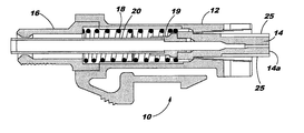
- FIG. 2 is cross-sectional side view of the preassembled multifiber connector of FIG. 1 .
- FIG. 3 is a perspective view of the windowless multifiber ferrule of the multifiber connector of FIG. 1 that illustrates the substantially rectangular shape of the windowless multifiber ferrule.
- FIG. 4 is a cross-sectional side view of the windowless multifiber ferrule of FIG. 3 taken along the line 4 — 4 illustrating the internal cavity defined by the ferrule that opens through the rear surface thereof.
- FIG. 5 is a cross-sectional view of the windowless multifiber ferrule of FIG. 3 taken along the line 5 — 5 which also illustrates the internal cavity defined by the windowless multifiber ferrule that opens through the rear surface thereof.
- FIG. 6 is a perspective view of a ferrule having a removable web according to another embodiment of the present invention.
- FIG. 7 is a cross-sectional side view of the ferrule having a removable web of FIG. 6 taken along line 7 — 7 .
- a multifiber connector 10 includes a plurality of components that are assembled upon the end portions of a plurality of optical fiber.
- the multifiber connector 10 includes a connector housing 12 defining a longitudinally extending internal cavity and a multifiber ferrule 14 that is at least partially disposed within the internal cavity defined by the connector housing 12 once the connector is assembled as shown in FIGS. 1 and 2.
- the multifiber ferrule 14 of the present invention is a windowless ferrule and has a substantially rectangular shape in lateral cross-section.
- the multifiber connector 10 of the present invention can also include a crimp body 16 that is operably connected to the connector housing 12 as well as a spring 18 disposed within the internal cavity defined by the connector housing 12 between the crimp body 16 and the ferrule 14 so as to urge the ferrule 14 forwardly relative to the connector housing 12 .
- the multifiber connector 10 can also include a lead-in tube 20 extending longitudinally through the crimp body 16 and the spring 18 and having one end disposed proximate the rear surface of the ferrule 14 for facilitating insertion of the plurality of optical fibers into the optical fiber bores 22 following preassembly of the connector 10 .
- the multifiber connector 10 can also include a divider disposed within the lead-in tube that defines a pair (depending on the number of optical fibers to be inserted) of lengthwise extending channels for separating the optical fibers and for leading the optical fibers into the optical fiber bores 22 defined by the multifiber ferrule 14 .
- the multifiber connector 10 can be preassembled prior to inserting a plurality of optical fibers into the optical fiber bores 22 .
- the multifiber ferrule 14 can be at least partially disposed within the internal cavity defined by the connector housing 12 such that the front surface of the multifiber ferrule 14 is exposed through a front end of the connector housing 12 . See FIG. 1 .
- the spring 18 is then disposed within the internal cavity defined by the connector housing 12 such that the forward end of the spring 18 contacts a rear surface of the ferrule 14 .
- the multifiber connector 10 of the present invention can also include an additional spring centering element 19 , if so desired.
- a crimp body 16 is then operably connected to the connector housing 12 in order to sandwich the spring 18 between the crimp body 16 and the ferrule 14 , thereby causing the spring 18 to urge the ferrule 14 forwardly relative to the connector housing 12 .
- the crimp body 16 includes a pair of forwardly extending arms 16 a, each of which carries an outwardly extending tab 16 b.
- a lead-in tube 20 can also be inserted through the crimp body 16 and into the spring 18 so as to extend longitudinally therethrough.
- one end of the lead-in tube is disposed proximate the rear surface of the ferrule 14 in order to facilitate the subsequent insertion of the plurality of optical fibers into the optical fiber bores 22 defined by the ferrule 14 .
- a divider can also be disposed within the lead-in tube in order to further separate the optical fibers and to lead the optical fibers into their optical fiber bores 22 .
- the multifiber connector 10 of the present invention can therefore be preassembled prior to inserting the plurality of optical fibers into the optical fiber bores 22 defined by the multifiber ferrule 14 .
- the preassembly of the multifiber connector 10 can be efficiently and, in some instances, automatically performed in a factory setting such that the preassembled multifiber connector 10 can then be shipped.
- the preassembled multifiber connector 10 can be easily mounted upon the end portions of the optical fibers, thereby increasing the efficiency with which optical fibers can be connectorized in the field since each of the components of the multifiber connector 10 need not be assembled in the field.
- a connector boot (not shown) and a crimp band (not shown) are typically slid over the end portions of the optical fibers. Thereafter, a protective jacket covering the optical fibers is preferably stripped back to expose the end portions of the optical fibers. Epoxy is then ejected, typically via a syringe, through the rear end of the multifiber ferrule 14 and into the optical fiber bores 22 . The end portions of the optical fibers are then inserted through the lead-in tube 20 and into respective optical fiber bores 22 defined by the multifiber ferrule 14 .
- the multifiber ferrule 14 is securely mounted to the end portions of the plurality of optical fibers.
- the strength members of the fiber optic cable are placed over the crimp body 16 and the crimp band is then slid forwardly along the plurality of optical fibers and over the rear portion of the crimp body 16 .
- the strength members of the fiber optic cable can be secured therebetween.
- the connector boot can be slid forwardly along the plurality of optical fibers and at least partially over the crimp band in order to provide additional strain relief for the plurality of optical fibers.
- the multifiber ferrule 14 of the present invention extends longitudinally between the opposed front and rear surfaces 14 a, 14 b.
- the multifiber ferrule 14 defines a plurality of optical fiber bores 22 that open through the front surface and through which respective optical fibers are inserted as described above.
- the multifiber ferrule 14 has a plurality of side surfaces 14 c with at least a portion of each side surface being planar.
- the multifiber ferrule 14 of the present invention is substantially rectangular in lateral cross-section and is compatible with MT-type connectors. As shown in FIGS.
- the forwardmost portion of the shaft of the multifiber ferrule 14 can define a pair of lengthwise extending grooves 25 for facilitating polishing of the front surface of the ferrule 14 .
- the corners of the ferrule 14 can be rounded or curved in order to increase the size of the ferrule 14 shoulder and correspondingly improve the seating of the ferrule 14 within the connector housing 12 of a multifiber connector 10 .
- the ferrule 14 depicted in FIG. 3 having the curved corners and the lengthwise extending grooves will be considered to be substantially rectangular since at least a portion of each major side surface is planar.
- Each side surface of the ferrule 14 of this embodiment is also a continuous surface so as to be free of any window that would otherwise open through a side surface of a conventional MTP ferrule and expose the optical fiber bores extending therethrough.
- the multifiber ferrule 14 of the present invention requires that the optical fibers be secured within the multifiber ferrule 14 in some fashion other than by injecting epoxy through a window as in conventional designs.
- epoxy is injected through the opening defined by the rear surface 14 b of the ferrule 14 and into the optical fiber bores 22 .
- the epoxy can be injected in various manners, the epoxy is typically injected with a syringe.
- the optical fibers are then inserted into the respective optical fiber bores 22 and are secured therein once the epoxy cures. Thereafter, the front surface 14 a of the ferrule 14 and the end portions of the optical fibers can be polished.
- the multifiber connector 10 of the present invention can be preassembled prior to inserting the plurality of optical fibers into the respective optical fiber bores 22 since the multifiber ferrule 14 of the present invention is windowless and, as such, does not permit epoxy to be inserted through a window as required by conventional MTP ferrules.
- the multifiber ferrule 14 preferably defines an internal cavity 24 that opens through the rear surface 14 b and is in communication with the plurality of optical fiber bores 22 .
- the internal cavity is preferably shaped and sized so as to facilitate the insertion of the optical fibers into the respective optical fiber bores 22 .
- the internal cavity tapers inwardly in a longitudinal direction extending from the rear surface of the ferrule 14 to the front surface 14 a of the ferrule 14 .
- the internal cavity defined by the multifiber ferrule 14 is largest proximate the rear surface of the ferrule 14 and is smaller proximate the optical fiber bores 22 .
- the internal cavity defined by the multifiber ferrule 14 can have a variety of configurations, the internal cavity of one advantageous embodiment has a stepped configuration that converges in a longitudinal direction extending from the rear surface of the ferrule 14 to the front surface of the ferrule 14 .
- the portion 24 a of the internal cavity 24 proximate the rear surface 14 b of the ferrule initially defines a 30° chamfer that leads into a circular section 24 b having a diameter of 1.5 millimeters. This first circular section then transitions to a second circular section 24 c having a diameter of 1.16 millimeters.
- the circular geometry of the internal cavity then tapers inwardly at an angle of 15° and transitions into a flat section 24 d that, in turn, leads to the typical ribbon-style entry to the optical fiber bores 22 .
- the transition from the flat geometry to the optical fiber bores 22 includes a transition region 24 e that tapers inwardly at 15° to reduce the effective area of the internal cavity to a size approximating the outside dimensions of the optical fiber bores 22 .
- the plurality of optical fibers can be fed through the internal cavity and inserted into the respective optical fiber bores 22 following preassembly of the connector 10 . Since epoxy has been injected into the optical fiber bores 22 prior to inserting the optical fibers through the internal cavity and into the optical fiber bores 22 , the windowless multifiber ferrule 14 of the present invention facilitates the preassembly of the multifiber connector 10 prior to inserting the plurality of optical fibers into the optical fiber bores 22 .
- the ferrule 30 is also provided according to another aspect of the present invention that is capable of being selectively converted from a windowless configuration to a windowed configuration.
- the ferrule includes a ferrule body extending longitudinally between opposed front and rear surfaces 32 , 34 and defining at least one optical fiber bore 35 opening through the front surface of the ferrule body.
- the ferrule body includes at least one side surface 36 .
- the side surface defines a well 38 that extends therethrough.
- the well 38 can be defined by any portion of a side surface, the well 38 is preferably defined at a location corresponding to the location at which a window is defined by conventional windowed ferrules.
- the ferrule body defines a substantially rectangular shape in lateral cross-section, the ferrule body preferably defines a well 38 in the medial portion of one of the major side surfaces 36 .
- the ferrule body of this aspect of the present invention further includes a removable web 40 at least partially covering the well and, more typically, completely covering the well.
- the ferrule 30 of this aspect of the present invention defines a windowless configuration in instances in which the web at least partially covers the well.
- the web is capable of being selectively removed from the well such that the uncovered well 38 forms a window through the side surface of the ferrule that opens into the at least one optical fiber bore 35 .
- a windowed configuration of the ferrule is defined.
- epoxy can be injected through the window defined by the well of the ferrule body in order to secure the optical fibers within the optical fiber bores defined by the ferrule.
- the edge portions 42 of the web that connect the web to the remainder of the ferrule body are preferably broken to thereby separate the web from the remainder of the ferrule body.
- the web can include a body portion 44 and an edge portion connecting the body portion to the remainder of the ferrule body.
- the edge portion is preferably thinner than the body portion to facilitate the selective removal of the web from the well 38 .
- the thickness of the edge portion is selected such that the web can be readily removed from the wall upon the application of a predetermined force while preventing the web from being removed from the wall upon most instances of inadvertent contact with the web.
- the web preferably has a thickness of about 0.5 mm at the edges of the web and is thicker in the middle to allow the entire window to be removed when desired.
- the removable web 40 can be disposed at any position within a well 38 .
- the removable web is typically disposed within a bottom portion of the well proximate the at least one fiber bore 35 as shown in crosssection in FIG. 7 .
- the well and the corresponding web can have a variety of sizes and shapes.
- the well and the corresponding web are sized such that the well opens into each of the plurality of optical fiber bores 35 defined by the ferrule in the windowed configuration such that epoxy can be readily inserted into each of the optical fiber bores 35 .
- the ferrule 30 can be selectively configured in either a windowed configuration or a windowless configuration.
- the ferrule can be utilized as a conventional windowed ferrule to permit epoxy to be injected through the window in order to bond the optical fibers within their respective optical fiber bores 35 .
- the ferrule prior to removing the web from the well 38 , the ferrule has a windowless configuration and can be utilized as described above in order to facilitate preassembly of a multifiber connector 10 prior to inserting the plurality of optical fibers into the respective optical fiber bores.
- the multifiber connector 10 of one advantageous embodiment of the present invention therefore includes a windowless multifiber ferrule 14 that is substantially rectangular in cross-section and is configured so as to permit the preassembly of the multifiber connector 10 prior to inserting the plurality of optical fibers into the optical fiber bores 22 .
- the multifiber connector 10 of this embodiment can advantageously be preassembled in the factory and can then be shipped to the field, at which time epoxy is injected and the end portions of the plurality of optical fibers are inserted into the optical fiber bores in order to mount the multifiber connector upon the optical fibers.
- a ferrule 30 is also provided according to another aspect of the present invention that can be selectively converted from a windowless configuration to a windowed configuration in order to be suitable for any of a variety of applications.
Abstract
Description
Claims (6)
Priority Applications (1)
| Application Number | Priority Date | Filing Date | Title |
|---|---|---|---|
| US10/039,372 US6499887B2 (en) | 1999-12-17 | 2001-12-31 | Windowless, rectangular ferrule in a preassembled multifiber connector and associated assembly method |
Applications Claiming Priority (2)
| Application Number | Priority Date | Filing Date | Title |
|---|---|---|---|
| US09/464,815 US6547449B1 (en) | 1999-12-17 | 1999-12-17 | Windowless, rectangular ferrule in a preassembled multifiber connector and associated assembly method |
| US10/039,372 US6499887B2 (en) | 1999-12-17 | 2001-12-31 | Windowless, rectangular ferrule in a preassembled multifiber connector and associated assembly method |
Related Parent Applications (1)
| Application Number | Title | Priority Date | Filing Date |
|---|---|---|---|
| US09/464,815 Division US6547449B1 (en) | 1999-12-17 | 1999-12-17 | Windowless, rectangular ferrule in a preassembled multifiber connector and associated assembly method |
Publications (2)
| Publication Number | Publication Date |
|---|---|
| US20020057870A1 US20020057870A1 (en) | 2002-05-16 |
| US6499887B2 true US6499887B2 (en) | 2002-12-31 |
Family
ID=23845344
Family Applications (2)
| Application Number | Title | Priority Date | Filing Date |
|---|---|---|---|
| US09/464,815 Expired - Lifetime US6547449B1 (en) | 1999-12-17 | 1999-12-17 | Windowless, rectangular ferrule in a preassembled multifiber connector and associated assembly method |
| US10/039,372 Expired - Lifetime US6499887B2 (en) | 1999-12-17 | 2001-12-31 | Windowless, rectangular ferrule in a preassembled multifiber connector and associated assembly method |
Family Applications Before (1)
| Application Number | Title | Priority Date | Filing Date |
|---|---|---|---|
| US09/464,815 Expired - Lifetime US6547449B1 (en) | 1999-12-17 | 1999-12-17 | Windowless, rectangular ferrule in a preassembled multifiber connector and associated assembly method |
Country Status (2)
| Country | Link |
|---|---|
| US (2) | US6547449B1 (en) |
| JP (1) | JP4933691B2 (en) |
Cited By (4)
| Publication number | Priority date | Publication date | Assignee | Title |
|---|---|---|---|---|
| US6623175B2 (en) * | 2001-07-09 | 2003-09-23 | The Furukawa Electric Co., Ltd. | Optical connector ferrule |
| US20050201691A1 (en) * | 2004-03-12 | 2005-09-15 | Mudd Ronald L. | Multi-fiber ferrule for coated optical fibers |
| US20100129031A1 (en) * | 2008-11-25 | 2010-05-27 | Danley Jeffrey D | Optical Ferrule Assemblies and Methods of Making the Same |
| US20100322568A1 (en) * | 2009-05-19 | 2010-12-23 | Adc Telecommunications, Inc. | Mechanical interface between a fiber optic cable and a fiber optic connector |
Families Citing this family (14)
| Publication number | Priority date | Publication date | Assignee | Title |
|---|---|---|---|---|
| US20040101251A1 (en) * | 2002-11-27 | 2004-05-27 | Fci Americas Technology, Inc. | Plastic optical connector |
| US7469091B2 (en) * | 2004-12-22 | 2008-12-23 | Tyco Electronics Corporation | Optical fiber termination apparatus and methods for using the same |
| US7359613B2 (en) * | 2005-05-27 | 2008-04-15 | Tyco Electronics Corporation | Optical fiber termination apparatus for taut sheath splicing and method for using the same |
| US7356237B2 (en) * | 2005-07-25 | 2008-04-08 | Tyco Electronics Corporation | Optical fiber cable termination apparatus |
| US7281856B2 (en) * | 2005-08-15 | 2007-10-16 | Molex Incorporated | Industrial optical fiber connector assembly |
| US20070036489A1 (en) * | 2005-08-15 | 2007-02-15 | Barbara Grzegorzewska | Industrial interconnect system incorporating transceiver module cage |
| US7756372B2 (en) * | 2006-02-22 | 2010-07-13 | Tyco Electronics Corporation | Fiber optic cable systems and kits and methods for terminating the same |
| US7668432B2 (en) * | 2007-01-31 | 2010-02-23 | Tyco Electronics Corporation | Multi-drop closure systems and methods for fiber optic cabling |
| JP4957363B2 (en) * | 2007-05-02 | 2012-06-20 | 住友電気工業株式会社 | Optical connector and optical connector assembling method |
| EP2828696B1 (en) * | 2012-03-20 | 2019-05-15 | Corning Optical Communications LLC | Simplified fiber optic connectors having lenses and method for making the same |
| CN109343178A (en) * | 2014-02-07 | 2019-02-15 | 泰科电子公司 | The optical power of hardening connects system |
| EP3224662A1 (en) * | 2014-11-26 | 2017-10-04 | Corning Optical Communications LLC | Transceivers using a pluggable optical body |
| JP1613186S (en) * | 2017-12-26 | 2018-09-10 | ||
| EP4073565A1 (en) * | 2019-12-13 | 2022-10-19 | US Conec, Ltd | Cover for a fiber optic ferrule and ferrule push |
Citations (4)
| Publication number | Priority date | Publication date | Assignee | Title |
|---|---|---|---|---|
| US5727102A (en) * | 1995-11-09 | 1998-03-10 | Electronics And Telecommunications Research Institute | Multifiber optical connector for optical ribbon cable |
| US5809191A (en) * | 1997-02-20 | 1998-09-15 | Lockheed Martin Corporation | Optical connector |
| US5896479A (en) * | 1995-12-22 | 1999-04-20 | Methode Electronics, Inc. | Massive parallel optical interconnect system |
| US6062740A (en) * | 1997-08-25 | 2000-05-16 | Sumitomo Electric Industries, Ltd. | Optical connector and method of making the same |
Family Cites Families (1)
| Publication number | Priority date | Publication date | Assignee | Title |
|---|---|---|---|---|
| KR100261307B1 (en) * | 1997-11-20 | 2000-07-01 | 이계철 | Manufacturing method of multifiber connector ferrule for ribbon-type optical cable |
-
1999
- 1999-12-17 US US09/464,815 patent/US6547449B1/en not_active Expired - Lifetime
-
2000
- 2000-12-18 JP JP2000384309A patent/JP4933691B2/en not_active Expired - Fee Related
-
2001
- 2001-12-31 US US10/039,372 patent/US6499887B2/en not_active Expired - Lifetime
Patent Citations (4)
| Publication number | Priority date | Publication date | Assignee | Title |
|---|---|---|---|---|
| US5727102A (en) * | 1995-11-09 | 1998-03-10 | Electronics And Telecommunications Research Institute | Multifiber optical connector for optical ribbon cable |
| US5896479A (en) * | 1995-12-22 | 1999-04-20 | Methode Electronics, Inc. | Massive parallel optical interconnect system |
| US5809191A (en) * | 1997-02-20 | 1998-09-15 | Lockheed Martin Corporation | Optical connector |
| US6062740A (en) * | 1997-08-25 | 2000-05-16 | Sumitomo Electric Industries, Ltd. | Optical connector and method of making the same |
Cited By (12)
| Publication number | Priority date | Publication date | Assignee | Title |
|---|---|---|---|---|
| US6623175B2 (en) * | 2001-07-09 | 2003-09-23 | The Furukawa Electric Co., Ltd. | Optical connector ferrule |
| US20050201691A1 (en) * | 2004-03-12 | 2005-09-15 | Mudd Ronald L. | Multi-fiber ferrule for coated optical fibers |
| US6971803B2 (en) | 2004-03-12 | 2005-12-06 | Corning Cable Systems Llc | Multi-fiber ferrule with an alignment portion |
| US20100129031A1 (en) * | 2008-11-25 | 2010-05-27 | Danley Jeffrey D | Optical Ferrule Assemblies and Methods of Making the Same |
| US8109679B2 (en) | 2008-11-25 | 2012-02-07 | Corning Cable Systems Llc | Optical ferrule assemblies and methods of making the same |
| US8523459B2 (en) | 2008-11-25 | 2013-09-03 | Corning Cable Systems Llc | Optical ferrule assemblies and methods of making the same |
| US20100322568A1 (en) * | 2009-05-19 | 2010-12-23 | Adc Telecommunications, Inc. | Mechanical interface between a fiber optic cable and a fiber optic connector |
| US8646989B2 (en) | 2009-05-19 | 2014-02-11 | Adc Telecommunications, Inc. | Mechanical interface between a fiber optic cable and a fiber optic connector |
| US9766413B2 (en) | 2009-05-19 | 2017-09-19 | Commscope Technologies Llc | Mechanical interface between a fiber optic cable and a fiber optic connector |
| US10247888B2 (en) | 2009-05-19 | 2019-04-02 | Commscope Technologies Llc | Mechanical interface between a fiber optic cable and a fiber optic connector |
| US10754102B2 (en) | 2009-05-19 | 2020-08-25 | Commscope Technologies Llc | Mechanical interface between a fiber optic cable and a fiber optic connector |
| US11243359B2 (en) | 2009-05-19 | 2022-02-08 | Commscope Technologies Llc | Mechanical interface between a fiber optic cable and a fiber optic connector |
Also Published As
| Publication number | Publication date |
|---|---|
| US20020057870A1 (en) | 2002-05-16 |
| JP2001183550A (en) | 2001-07-06 |
| US6547449B1 (en) | 2003-04-15 |
| JP4933691B2 (en) | 2012-05-16 |
Similar Documents
| Publication | Publication Date | Title |
|---|---|---|
| US6499887B2 (en) | Windowless, rectangular ferrule in a preassembled multifiber connector and associated assembly method | |
| US6379054B2 (en) | Field installable multifiber connector | |
| US6068410A (en) | Splice housing assembly and associated assembly method for mechanically decoupling a ferrule from a splice body | |
| US7036993B2 (en) | Pin retainer for fiber optic connector and associated fabrication method | |
| US6669377B2 (en) | Fiber optic connector and an associated pin retainer | |
| CA2151071C (en) | Bend-limiting apparatus for a cable | |
| US4684205A (en) | Fiber optic connector with compensating mechanism | |
| US6439780B1 (en) | Field-installable fiber optic ribbon connector and installation tool | |
| US4526438A (en) | Alignment sleeve for fiber optic connectors | |
| US20170254967A1 (en) | Optical ferrule for multi-fiber cable and hardened multi-fiber optic connector therefore | |
| US7192194B2 (en) | Universal adapter for fiber optic connectors | |
| EP1431786A2 (en) | Angled spring push for optical ribbon cable | |
| EP1148364A2 (en) | Strain relief clamping mechanism for an optical fiber connector | |
| US5953475A (en) | Fiber optic plug connector | |
| US6416236B1 (en) | Ferrule for facilitating fiber-to-fiber contact and associated fabrication method | |
| KR100713430B1 (en) | Optical plug connector, method of manufacture and assembly tool | |
| US5915057A (en) | Connector for a fiber optic cable | |
| US20210132297A1 (en) | Dual spring multi-fiber optic connector | |
| EP0973051A1 (en) | Pin retainer and associated method for assembling a fiber optic connector | |
| EP0262765B1 (en) | Fiber optic connector, tool for assembling fiber optic connector and method of assembling fiber optic connectors | |
| EP0608026A2 (en) | Multiple connector for multi-fibre optic ribbons | |
| EP0961144A1 (en) | Fiber optic connector having a spring positioner | |
| CN114730043A (en) | Optical fiber connector, subassembly and method of manufacture | |
| JP2913549B1 (en) | Multi-core optical connector | |
| JP2930004B2 (en) | Multi-core optical connector |
Legal Events
| Date | Code | Title | Description |
|---|---|---|---|
| AS | Assignment |
Owner name: COMING CABLE SYSTEMS LLC, NORTH CAROLINA Free format text: ASSIGNMENT OF ASSIGNORS INTEREST;ASSIGNORS:DEAN, JR., DAVID L.;GIEBEL, MARKUS A.;LUTHER, JAMES P.;AND OTHERS;REEL/FRAME:012889/0915 Effective date: 19991216 |
|
| STCF | Information on status: patent grant |
Free format text: PATENTED CASE |
|
| FPAY | Fee payment |
Year of fee payment: 4 |
|
| AS | Assignment |
Owner name: JAMES HARDIE TECHNOLOGY LIMITED,IRELAND Free format text: ASSIGNMENT OF ASSIGNORS INTEREST;ASSIGNOR:JAMES HARDIE INTERNATIONAL FINANCE B.V.;REEL/FRAME:024103/0809 Effective date: 20091215 |
|
| FPAY | Fee payment |
Year of fee payment: 8 |
|
| FPAY | Fee payment |
Year of fee payment: 12 |
|
| AS | Assignment |
Owner name: CCS TECHNOLOGY, INC., DELAWARE Free format text: ASSIGNMENT OF ASSIGNORS INTEREST;ASSIGNOR:CORNING CABLE SYSTEMS LLC;REEL/FRAME:033600/0033 Effective date: 20030124 |
|
| AS | Assignment |
Owner name: CORNING OPTICAL COMMUNICATIONS LLC, NORTH CAROLINA Free format text: MERGER;ASSIGNORS:CCS TECHNOLOGY, INC.;CORNING OPTICAL COMMUNICATIONS BRANDS, INC.;REEL/FRAME:043601/0427 Effective date: 20170630 |