US6499353B1 - Method and apparatus for remote measurement of physical properties inside a sealed container - Google Patents
Method and apparatus for remote measurement of physical properties inside a sealed container Download PDFInfo
- Publication number
- US6499353B1 US6499353B1 US09/692,511 US69251100A US6499353B1 US 6499353 B1 US6499353 B1 US 6499353B1 US 69251100 A US69251100 A US 69251100A US 6499353 B1 US6499353 B1 US 6499353B1
- Authority
- US
- United States
- Prior art keywords
- recited
- container
- magnet
- magnetic field
- receiver
- Prior art date
- Legal status (The legal status is an assumption and is not a legal conclusion. Google has not performed a legal analysis and makes no representation as to the accuracy of the status listed.)
- Expired - Lifetime
Links
Images


Classifications
-
- G—PHYSICS
- G01—MEASURING; TESTING
- G01K—MEASURING TEMPERATURE; MEASURING QUANTITY OF HEAT; THERMALLY-SENSITIVE ELEMENTS NOT OTHERWISE PROVIDED FOR
- G01K1/00—Details of thermometers not specially adapted for particular types of thermometer
- G01K1/02—Means for indicating or recording specially adapted for thermometers
- G01K1/024—Means for indicating or recording specially adapted for thermometers for remote indication
-
- G—PHYSICS
- G01—MEASURING; TESTING
- G01K—MEASURING TEMPERATURE; MEASURING QUANTITY OF HEAT; THERMALLY-SENSITIVE ELEMENTS NOT OTHERWISE PROVIDED FOR
- G01K1/00—Details of thermometers not specially adapted for particular types of thermometer
- G01K1/14—Supports; Fastening devices; Arrangements for mounting thermometers in particular locations
-
- G—PHYSICS
- G01—MEASURING; TESTING
- G01L—MEASURING FORCE, STRESS, TORQUE, WORK, MECHANICAL POWER, MECHANICAL EFFICIENCY, OR FLUID PRESSURE
- G01L19/00—Details of, or accessories for, apparatus for measuring steady or quasi-steady pressure of a fluent medium insofar as such details or accessories are not special to particular types of pressure gauges
- G01L19/08—Means for indicating or recording, e.g. for remote indication
- G01L19/086—Means for indicating or recording, e.g. for remote indication for remote indication
-
- G—PHYSICS
- G01—MEASURING; TESTING
- G01L—MEASURING FORCE, STRESS, TORQUE, WORK, MECHANICAL POWER, MECHANICAL EFFICIENCY, OR FLUID PRESSURE
- G01L7/00—Measuring the steady or quasi-steady pressure of a fluid or a fluent solid material by mechanical or fluid pressure-sensitive elements
- G01L7/02—Measuring the steady or quasi-steady pressure of a fluid or a fluent solid material by mechanical or fluid pressure-sensitive elements in the form of elastically-deformable gauges
- G01L7/04—Measuring the steady or quasi-steady pressure of a fluid or a fluent solid material by mechanical or fluid pressure-sensitive elements in the form of elastically-deformable gauges in the form of flexible, deformable tubes, e.g. Bourdon gauges
- G01L7/043—Measuring the steady or quasi-steady pressure of a fluid or a fluent solid material by mechanical or fluid pressure-sensitive elements in the form of elastically-deformable gauges in the form of flexible, deformable tubes, e.g. Bourdon gauges with mechanical transmitting or indicating means
-
- G—PHYSICS
- G01—MEASURING; TESTING
- G01L—MEASURING FORCE, STRESS, TORQUE, WORK, MECHANICAL POWER, MECHANICAL EFFICIENCY, OR FLUID PRESSURE
- G01L9/00—Measuring steady of quasi-steady pressure of fluid or fluent solid material by electric or magnetic pressure-sensitive elements; Transmitting or indicating the displacement of mechanical pressure-sensitive elements, used to measure the steady or quasi-steady pressure of a fluid or fluent solid material, by electric or magnetic means
- G01L9/0026—Transmitting or indicating the displacement of flexible, deformable tubes by electric, electromechanical, magnetic or electromagnetic means
-
- G—PHYSICS
- G01—MEASURING; TESTING
- G01L—MEASURING FORCE, STRESS, TORQUE, WORK, MECHANICAL POWER, MECHANICAL EFFICIENCY, OR FLUID PRESSURE
- G01L9/00—Measuring steady of quasi-steady pressure of fluid or fluent solid material by electric or magnetic pressure-sensitive elements; Transmitting or indicating the displacement of mechanical pressure-sensitive elements, used to measure the steady or quasi-steady pressure of a fluid or fluent solid material, by electric or magnetic means
- G01L9/14—Measuring steady of quasi-steady pressure of fluid or fluent solid material by electric or magnetic pressure-sensitive elements; Transmitting or indicating the displacement of mechanical pressure-sensitive elements, used to measure the steady or quasi-steady pressure of a fluid or fluent solid material, by electric or magnetic means involving the displacement of magnets, e.g. electromagnets
-
- G—PHYSICS
- G01—MEASURING; TESTING
- G01K—MEASURING TEMPERATURE; MEASURING QUANTITY OF HEAT; THERMALLY-SENSITIVE ELEMENTS NOT OTHERWISE PROVIDED FOR
- G01K2215/00—Details concerning sensor power supply
Definitions
- the present invention relates generally to methods and apparatus for remotely measuring physical properties inside a sealed container without penetrating the walls of the container, and more particularly to a method for measuring the pressure, temperature, or other physical properties inside a non-magnetic, stainless steel storage container storing nuclear fuel and/or other hazardous products that can be implemented without requiring a power supply inside or outside of the container.
- DOE storage containers used by the United States Department of Energy (DOE) that need to be monitored for pressure.
- Conventional sensing systems that penetrate or tap into and through the walls of the container and affix a sensor to the inside of the container are avoided, because any penetration of the sealed container is a potential release site for the gas or liquid present in the container.
- These DOE storage containers are typically cylindrical in shape and are made of stainless steel. They can range from several inches in diameter and several feet in height to several feet in diameter and tens of feet in height.
- the most direct method for determining if there is a pressure build-up inside a container is to visually inspect the container for physical deformation.
- the obvious problem with this approach is that the level of the pressure is unknown and may have already exceeded the safe limits of the container by the time the deformation is visually detectable.
- magnetic coupling systems have been used, including a sensor apparatus and a reading apparatus separated from each other by a non-metallic wall.
- Two examples are fluid flow meters and smart sensors for structures.
- none of these systems have been used for interrogating the inside of a sealed container, especially one containing nuclear waste materials, and none have been used where the distance between the sensing and readout elements is very large (e.g., many inches).
- U.S. Pat. No. 3,949,606 describes counting the rotations of a flow meter using permanent magnets mounted on rotational elements on both sides of a non-magnetic wall.
- Various configurations and strengths of magnets have been used to accurately count the number of rotations of a flow chamber.
- an inductive-type rotary encoder that has a stator with a conductive pattern on one side and a rotor with a conductive pattern facing the stator, and apparatus for inductively coupling and reading the angular position of the stator relative to the rotor.
- a preferred embodiment of the present invention includes a method and apparatus for measuring gas pressure inside a sealed magnetic container.
- a transducer inside the container is responsive to pressure, having a Bourdon tube connected to a first pivotally mounted permanent magnet.
- the Bourdon tube has an oval cross section and a tube axis following a curved contour.
- a proximal end of the tube is open to the container atmosphere, and a closed distal end of the tube is coupled to the first magnet by means of a geared mechanism.
- a second permanent magnet is pivotally mounted and positioned exterior to the container, with the first and second magnets having a common pivot axis. The second magnet is rigidly attached to a pointer for indicating a pressure value indicated on a calibrated scale.
- An advantage of the present invention is that it provides a safe method of measuring pressure in a nuclear waste container.
- Another advantage of the present invention is that it provides a safe method of measuring a physical property inside a sealed container without penetrating the walls of the container.
- a further advantage of the present invention is that it provides a method of measuring pressure in a sealed container without requiring electrical power.
- FIG. 1 is a block illustration of the preferred embodiment of the present invention
- FIG. 2 is a simplified illustration of an embodiment of the present invention for measuring pressure inside a sealed container
- FIG. 3 illustrates further details of the apparatus of FIG. 2
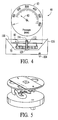
- FIG. 4 is an exploded view of the parts of the transmitter
- FIG. 5 shows details of the receiver/read-out apparatus
- FIG. 6 shows the transmitter in assembled form
- FIG. 7 is a plot of data collected with a prototype device of the present invention for measuring pressure from 0 to 100 psi for all four orientations of the measurement apparatus;
- FIG. 8 is a graph showing predicted operation of a pressure measurement apparatus with improperly sized magnets.
- FIG. 9 shows the output of a prototype of the present invention with operations between 0 and 100 psi.
- an apparatus 10 for determining a physical property of an environment inside a sealed container 18 .
- the apparatus 10 includes a transmitter apparatus 12 separated from a receiver apparatus 14 by a wall 16 of the container 18 .
- the container 18 wall 16 is preferably constructed of non-magnetic or weakly magnetic material, such as metal, plastic, or composite material, and the container is preferably used for storage of nuclear waste material.
- the preferred material for the wall 16 is non-magnetic or weakly magnetic stainless steel, used in containers for storage of nuclear products.
- Other non-magnetic or weakly magnetic metals, plastics, and composite materials are also included in the spirit of the present invention.
- magnetic metals are also included in the spirit of the present invention.
- the transmitter apparatus 12 is self contained, and does not require any physical connections/holes through the wall 16 for supply, etc.
- the transmitter 12 is constructed to respond to a value of a physical property of the inside 20 of the container 18 by causing a characteristic of a magnetic field 22 such as orientation to give an indication of the value of the physical property.
- the physical property for example, can be the pressure of a gas or liquid inside the container 18 , or it could be the temperature inside the container.
- the transmitter 12 includes a transmitter transducer 24 responsive to the value of the physical property to cause a magnetic field generator 26 to provide the magnetic field 22 with a characteristic indicative of the value (for example a magnetic field orientation).
- the transducer 24 When pressure is measured, the transducer 24 includes an aneroid reference, symbolically represented by line 11 that has communication 13 with the fluid/gas inside the sealed container.
- the term “radiate” may be used in the following text and claims as a general term referring to the existence or creation of a magnetic field, even though in the case of a permanent magnet the field is not usually moving outward, but is static and therefore does not require an energy supply to sustain energy radiated from the magnet.
- the receiver 14 includes a receiver transducer 28 responsive to the field 22 to cause an indicator 30 to provide a communicative indication of the value of the physical property (temperature, pressure, etc.).
- the communicative indication can be any of various types, including display apparatus such as a needle and scale, or a digital read-out using LEDs, etc.
- magnetic field generator applies to any of the devices known by those skilled in the art for providing a magnetic field, and is preferably achieved using permanent magnets.
- characteristic applies to any property of a magnetic field that can be altered by a transducer, such as the Bourdon tube described in the following text, to give an indication of the value of the physical property.
- physical property applies to any measurable parameter inside the container, including the pressure or temperature of the substance inside the container.
- FIG. 2 of the drawing is a simplified illustration of an embodiment of the present invention for measuring the pressure inside a container.
- a transmitter 32 inside a container 34 is shown in an exploded view, and includes a sealed housing 35 having a cap 36 and base 38 that in assembly are welded or otherwise assembled to create a sealed enclosure for a transmitter transducer 40 and field generator 42 .
- the transducer 40 is a Bourdon tube apparatus including a Bourdon tube 44 shown as a semicircular structure with an oval cross section, sealed at a distal end 46 , and connected to an inlet tube 48 at a proximal end 50 .
- the inlet tube 48 is connected to a fitting 52 that provides sealed passage through a channel 54 in the base 38 to open the inside of tube 44 to the container 34 internal atmosphere 56 (liquid or gas).
- the distal end 46 of the tube 44 is pivotally attached to a mechanism (represented by arm 58 ) that extends to a pinion shaft 60 .
- the pinion shaft 60 is pivotally mounted (not shown) and extends upward and is rigidly connected to a bar magnet 62 functioning as the field generator 42 .
- the pressure in the sealed housing 35 is a constant at a given temperature, or a constant if a vacuum. Since the inside of the Bourdon tube 44 is open to the inside 56 of the container 34 , the pressure in the tube 44 is the same as in the container 34 interior 56 .
- the pressure in the tube 44 is greater than in the housing 35 , the pressure will cause the tube to straighten, i.e. unwind, to a degree depending on the value of pressure applied resulting in a rotation of the pin 60 and therefore also the magnet 62 , thereby changing the orientation/position of the magnetic field 64 radiated from the magnet.
- the transmitter 32 responds to a value of the physical property (pressure) by the container 34 and transmits (radiates) a magnetic field with a characteristic (directional orientation) indicative of a value (pressure level) of the physical property (pressure).
- the transducer Bourdon tube 44 is an example of any of various types of transducers that can be used to transfer a value of a physical property, such as temperature or pressure, into a particular position of a mechanical element.
- the position of the element is used to influence a magnetic field generator, for example magnet 62 , to provide a field characteristic such as field orientation to indicate the value of the physical property.
- a themostat such as in a furnace uses a metal or metals having a particular material dimension sensitive to temperature for the purpose of controlling a switch to turn the furnace off and on.
- material dimension sensitivity/movement can be used to adjust the position/rotation of a magnet to give indication of a value of a physical property.
- the transmitter 32 is preferably positioned close to the inside of container 34 wall portion 66
- the receiver 68 is positioned close to the outside of the wall portion 66
- the receiver has a magnet 70 attached to a pin 72 that is pivotally mounted to the base 74 of the receiver housing 76 .
- the pin 72 extends upward through the top 78 and attaches to a pointer 80 for pointing to a calibrated scale 82 indicative of the pressure in the container 34 .
- the field 64 transmitted (radiated/extended) from the magnet 62 of transmitter 32 extends to the wall 66 and passes through if the wall is non-magnetic.
- the field aligns magnetic domains in the magnetic wall, and the magnetized wall portion 66 then radiates-extends a corresponding magnetic field exterior to the container 34 .
- the magnet 70 of the receiver being free to rotate, then aligns itself with the field extended by the magnet 62 , which is in a position dependent on the container 34 pressure.
- the resulting orientation of the magnet 70 is transferred via pin 72 to pointer 80 to point at the scale 82 indicating the container pressure as calibrated.
- the apparatus of FIG. 2 is illustrative of a preferred embodiment of the present invention.
- Other transmitter and receiver constructions for responding to a container physical property transferring a magnetic indication of a value of the property through a magnetic wall and detecting the magnetic field and displaying a parameter value indication will be apparent to those skilled in the art, and these are included in the spirit of the present invention.
- the transducer 40 is a temperature sensitive apparatus for providing positioning of a magnet for indication of the container interior temperature
- the receiver 68 would be appropriately calibrated.
- a permanent magnet or a set of permanent magnets in the receiver is preferred, alternate embodiments include a magnetic sensing coil to measure the position of the magnetic field produced by the transmitting magnet, and a LCD to display the value of the sensed quantity.
- the scale 82 and pointer 80 of the receiver could be replaced with a disk attached to the pin 72 .
- the disk could have graduations imprinted on it which could be “read” as in an optical encoder system to provide a parameter value (temperature, pressure, etc.) on an electrical (LED etc.) display.
- FIG. 3 is an exploded view of the parts of the transmitter 32 .
- pressure applied to the inlet port 84 of a Bourdon tube 86 causes the Bourdon tube to flex in proportion to the applied pressure.
- the base end of a sector gear 88 is pivotally attached to the Bourdon tube 86 .
- the sector gear 88 is caused to rotate about a pivot pin 90 that is used for that purpose as well as to calibrate the extent of the angular motion for a given pressure. Calibration is accomplished by locating the pivot point variously in a slot in the sector gear 88 .
- the sector gear 88 engages with a gear 92 and causes an angular rotation of the pinion shaft 94 that is proportional to the applied pressure, with the proportionality constant being determined by the location of the pivot pin 90 in the slot.
- a magnet support plate 96 and a boss 98 are welded together and supported on the pinion shaft 94 by a thrust bearing 100 that rests on the sector gear support frame 102 .
- the end of the pinion shaft 94 is welded to the boss 98 .
- the magnet plate 96 Prior to welding the boss 98 to the pinion shaft 94 , the magnet plate 96 is aligned to an index pin 104 of the receiver (see FIG. 4) by means of alignment holes 106 .
- a magnet 108 is installed on the magnet support plate 96 with its North pole 110 oriented over the alignment hole 96 in the support plate 96 .
- the proper alignment between the transmitting apparatus and the receiver apparatus can be achieved by affixing the index pins after the magnet 108 is installed in the transmitting apparatus.
- the permanent magnet 70 is shown suspended from a jeweled mount 112 using a capped tube 114 and installed in a case 116 with a glass cover 118 .
- the needle 80 is attached to the magnet 70 by way of the tube 114 and is used to indicate the measured pressure on a dial face/scale 82 .
- the receiver 68 incorporates the index pin 104 . Alignment between the transmitter and receiver is accomplished by aligning the index pins to axially align the pin 120 of the receiver 68 with the pivot pin 94 of the transmitter 32 .
- the mechanical gauge of the receiver 68 could be replaced with an electronic output such as an optical encoder as discussed above.
- FIG. 6 shows the data collected with a prototype of the present invention for measuring pressure over a range of 0 to 100 psi for all four orientations of the gauge/measurement apparatus with respect to magnetic North.
- the transmitter 32 and the receiver 68 are separated by air, and the distance between them is 2 inches.
- the calibration curve is highly linear, because the strength of the magnets are sized to operate efficiently over this separation distance with respect to the earth's magnetic field and the spring elasticity of the Bourdon tube.
- the nonlinear response between 0 and 10 psi is due to the very low spring constant of the Bourdon tube.
- the precision of one standard deviation of the pressure data of a regression line fit to all of the data (at all orientations of the sensor with respect to magnetic North) is ⁇ 3 psi.
- FIG. 7 shows the predicted operation of a pressure measurement apparatus with magnets that results in only partial compensation of the earth's magnetic field. As shown in the figure, incomplete compensation of the earth's magnetic field results in “S-shaped” curves. Complete compensation would remove the “S-shaped” response and show a linear response.
- FIG. 7 includes four S shaped curves representing the four positions (N, S, E, W), and one linear line as a reference.
- FIG. 8 shows the output of a prototype of the present invention described above for measuring pressure. Operation is between 0 and 100 psi with a 2-in. separation between the transmitter and receiver in the top portion of a specialized stainless container for storing spent nuclear fuel. Each curve is data for a particular test run, and magnet orientation, where T6 R1-N is for Test 6, Run 1 with a magnet orientation of North.
- FIG. 9 shows data taken with a second pressure measurement apparatus operating between 0 and 600 psi at an 8-in. separation distance. The apparatus was positioned in the top portion of the specialized container. While both units can be used to measure the pressure inside the “closed container,” all they need to do in actual operation is to indicate when a specific pressure has been reached, somewhere between 50 and 90% of the operational range of each transmitter.
- FIGS. 8 and 9 were obtained by slowly increasing the pressure from one set point to the next (typically, in 40 psi increments for the 600 psi apparatus, and in 10 psi increments for the 100 psi apparatus) and reading and recording the applied and measured pressures on a data sheet. Test data were obtained for each of the principal orientations of the pressure apparatus with respect to magnetic North. Several test sequences were conducted.
- FIG. 8 The results from nine test runs are shown in FIG. 8 for the 100-psi apparatus, and eight test runs are shown in FIG. 9 for the 600-psi apparatus.
- FIGS. 7 and 8 Also shown in FIGS. 7 and 8 is the “ideal” curve, where the measured pressure would equal the applied pressure plus about 15 psi (since the MCO gauge is an absolute pressure sensor). It is seen that there is good test-to-test repeatability in the data. That the individual data plots do not show any significant differences with magnetic orientation (denoted in the plot legend) indicates that the transmitter magnets have been properly designed so as to compensate for the effects the earth's magnetic field would otherwise have on the measurement system. When the pressure is lowered for both units, some hysteresis is observed due to drag in the systems produced by the mass of the magnet acting upon the thrust bearing in the transmitter.
- FIG. 9 shows that the behavior of the 600 psi transmitter is not responding well at low pressures. This is because the Bourdon tube has a sector gear with a pivot pin that has some excess clearance in it. With only the (usual) weight of a thin needle attached to the Bourdon tube, an anti-backlash spring in the sector gear mechanism maintains the pivot pin against one side of the sector gear. With the heavy magnet installed—needed to reach out the required 8.5 inches—the anti-backlash spring is ineffective, allowing a “dead band” to develop. There are a number of ways to reduce or eliminate this deadband. One way of reducing or eliminating the deadband is to insert a shim in the sector gear 88 to reduce the play between the sector gear 88 and the pivot pin 90 .
- FIG. 8 shows a plot of the average of nine tests of the 100 psi apparatus.
- the data shows the points collected at 10 psi intervals.
- the “dead band” is apparent in the 100 psi data also, but it is not as significant as the 600 psi unit. This is because—in the 100 psi transmitter—the magnet is much smaller that in the 600 psi transmitter (because it has to only reach out about 2 inches to affect the readout) and is thus much less massive.
- the average error in this data is about 2.5 psi or about 3% of full scale.
Abstract
Description
Claims (27)
Priority Applications (1)
| Application Number | Priority Date | Filing Date | Title |
|---|---|---|---|
| US09/692,511 US6499353B1 (en) | 1999-10-20 | 2000-10-18 | Method and apparatus for remote measurement of physical properties inside a sealed container |
Applications Claiming Priority (2)
| Application Number | Priority Date | Filing Date | Title |
|---|---|---|---|
| US16049399P | 1999-10-20 | 1999-10-20 | |
| US09/692,511 US6499353B1 (en) | 1999-10-20 | 2000-10-18 | Method and apparatus for remote measurement of physical properties inside a sealed container |
Publications (1)
| Publication Number | Publication Date |
|---|---|
| US6499353B1 true US6499353B1 (en) | 2002-12-31 |
Family
ID=22577093
Family Applications (1)
| Application Number | Title | Priority Date | Filing Date |
|---|---|---|---|
| US09/692,511 Expired - Lifetime US6499353B1 (en) | 1999-10-20 | 2000-10-18 | Method and apparatus for remote measurement of physical properties inside a sealed container |
Country Status (5)
| Country | Link |
|---|---|
| US (1) | US6499353B1 (en) |
| EP (1) | EP1257797A4 (en) |
| JP (1) | JP2003512664A (en) |
| AU (1) | AU1216101A (en) |
| WO (1) | WO2001029530A1 (en) |
Cited By (16)
| Publication number | Priority date | Publication date | Assignee | Title |
|---|---|---|---|---|
| US20030020466A1 (en) * | 2001-07-26 | 2003-01-30 | Lewis Clifford William | Electromechanical rotation sensing device |
| US20030112146A1 (en) * | 2001-12-17 | 2003-06-19 | Sobel Jay Richard | Visual indication equipment operation |
| US20040055391A1 (en) * | 2002-06-28 | 2004-03-25 | Douglas Dennis G. | Method and apparatus for remotely monitoring corrosion using corrosion coupons |
| US6854335B1 (en) | 2003-12-12 | 2005-02-15 | Mlho, Inc. | Magnetically coupled tire pressure sensing system |
| US20060006994A1 (en) * | 2003-02-15 | 2006-01-12 | Moser George G | Tire pressure monitoring system and method of using same |
| US20060021443A1 (en) * | 2004-07-29 | 2006-02-02 | Buchanan Steven O | Gauge having a magnetically driven pointer rotation device |
| US7071686B1 (en) | 2000-08-30 | 2006-07-04 | Mlho, Inc. | Magnetic liquid crystal display |
| US20070113623A1 (en) * | 2004-07-07 | 2007-05-24 | Jimmy Wolford | Method and apparatus for storage tank leak detection |
| US20070186623A1 (en) * | 2004-07-07 | 2007-08-16 | Jimmy Wolford | System and method for detecting and quantifying changes in the mass content of liquid storage containers |
| US20080190172A1 (en) * | 2005-06-02 | 2008-08-14 | Glaxo Group Limited | Inductively Powered Remote Oxygen Sensor |
| US20100090828A1 (en) * | 2008-10-08 | 2010-04-15 | Kwj Engineering | Sensing and Reporting Devices, Systems and Methods |
| US20100212404A1 (en) * | 2009-02-23 | 2010-08-26 | Mass Technology Corporation | Method and apparatus for leak detection in horizontal cylindrical storage tanks |
| US20130079995A1 (en) * | 2011-09-23 | 2013-03-28 | Ford Global Technologies, Llc | Dual-chamber impact detector |
| US9995605B2 (en) * | 2015-04-16 | 2018-06-12 | Prospine Co., Ltd. | Pressure gauge |
| WO2019194695A1 (en) * | 2018-04-02 | 2019-10-10 | National Institute For Research And Development In Microtechnologies - Imt București | Pressure sensor for hostile environments |
| US11162861B2 (en) * | 2019-04-24 | 2021-11-02 | Lawrence Livermore National Security, Llc | Magnetically coupled pressure sensor |
Families Citing this family (2)
| Publication number | Priority date | Publication date | Assignee | Title |
|---|---|---|---|---|
| DE102008043649A1 (en) * | 2008-11-11 | 2010-05-12 | Wika Alexander Wiegand Gmbh & Co. Kg | pressure monitor |
| JP7025812B1 (en) * | 2021-09-08 | 2022-02-25 | 株式会社品川通信計装サービス | Pressure information acquisition method of food and drink storage container, pressure information acquisition device of food and drink storage container, and pressure or temperature information acquisition system in a series of food and drink storage containers |
Citations (24)
| Publication number | Priority date | Publication date | Assignee | Title |
|---|---|---|---|---|
| US2050629A (en) | 1934-05-11 | 1936-08-11 | Leeds & Northrup Co | Electric telemetering system |
| US2935875A (en) | 1954-11-15 | 1960-05-10 | Licentia Gmbh | Device for electrically tele-transmitting the measured value of pressure indicators |
| US3338101A (en) | 1965-10-21 | 1967-08-29 | Stewart Warner Corp | Bourdon tube gauges |
| US3645140A (en) | 1970-06-15 | 1972-02-29 | Dwyer Instr | Pressure gauge |
| US3777565A (en) | 1972-08-03 | 1973-12-11 | Gamon Calmet Ind Inc | Magnetic converter for water meters |
| US3789668A (en) | 1972-08-23 | 1974-02-05 | Dresser Ind | Overload protected bourdon tube |
| US3807232A (en) | 1972-08-23 | 1974-04-30 | Dresser Ind | Explosion proof gauge transducer |
| US3857219A (en) | 1972-08-23 | 1974-12-31 | Dresser Ind | Overload protected bourdon tube |
| US3949606A (en) | 1973-09-10 | 1976-04-13 | Blancett Joe H | Fluid meter and adapter units therefor |
| US3989911A (en) | 1975-09-05 | 1976-11-02 | Perry Joseph A | Magnetic differential pressure switch |
| US3998179A (en) | 1973-12-17 | 1976-12-21 | Dover Corporation | Apparatus for operating a pressure gauge or the like |
| US4023410A (en) | 1974-07-24 | 1977-05-17 | Aquametro Ag | Fluid flow meter |
| US4122392A (en) * | 1975-08-20 | 1978-10-24 | Nippon Steel Corporation | System of detecting a change in the charge put in a metallurgical furnace or the like |
| US4339955A (en) | 1980-08-29 | 1982-07-20 | Aisin Seiki Company, Ltd. | Pressure sensor |
| US4717873A (en) | 1985-11-12 | 1988-01-05 | Westinghouse Electric Corp. | Magnetic displacement transducer system having a magnet that is movable in a tube whose interior is exposed to a fluid and having at least one magnetometer outside the tube |
| US4891987A (en) | 1988-11-25 | 1990-01-09 | Stockton William E | Magnetic linkage for bourdon tube gauges |
| US4998863A (en) | 1987-04-11 | 1991-03-12 | Franz Klaus Union Armaturen Pumpen Gmbh & Co. | Magnetic pump drive |
| US5081876A (en) | 1987-09-03 | 1992-01-21 | Carrier Corporation | Slide valve position indicator and magnetic coupler |
| US5150115A (en) | 1990-12-13 | 1992-09-22 | Xerox Corporation | Inductive type incremental angular position transducer and rotary motion encoder having once-around index pulse |
| US5284061A (en) * | 1992-09-21 | 1994-02-08 | Seeley Eric E | Integral pressure sensor |
| US5392653A (en) | 1992-06-03 | 1995-02-28 | Allergan, Inc. | Pressure transducer magnetically-coupled interface complementing minimal diaphragm movement during operation |
| US5433115A (en) | 1993-06-14 | 1995-07-18 | Simmonds Precision Products, Inc. | Contactless interrogation of sensors for smart structures |
| US6067855A (en) * | 1999-05-04 | 2000-05-30 | Advanced Micro Devices, Inc. | Apparatus and method for measuring liquid level in a sealed container |
| US6182514B1 (en) | 1999-07-15 | 2001-02-06 | Ut-Battelle, Llc | Pressure sensor for sealed containers |
-
2000
- 2000-10-18 WO PCT/US2000/028939 patent/WO2001029530A1/en active Application Filing
- 2000-10-18 US US09/692,511 patent/US6499353B1/en not_active Expired - Lifetime
- 2000-10-18 EP EP00973674A patent/EP1257797A4/en not_active Withdrawn
- 2000-10-18 JP JP2001532073A patent/JP2003512664A/en active Pending
- 2000-10-18 AU AU12161/01A patent/AU1216101A/en not_active Abandoned
Patent Citations (24)
| Publication number | Priority date | Publication date | Assignee | Title |
|---|---|---|---|---|
| US2050629A (en) | 1934-05-11 | 1936-08-11 | Leeds & Northrup Co | Electric telemetering system |
| US2935875A (en) | 1954-11-15 | 1960-05-10 | Licentia Gmbh | Device for electrically tele-transmitting the measured value of pressure indicators |
| US3338101A (en) | 1965-10-21 | 1967-08-29 | Stewart Warner Corp | Bourdon tube gauges |
| US3645140A (en) | 1970-06-15 | 1972-02-29 | Dwyer Instr | Pressure gauge |
| US3777565A (en) | 1972-08-03 | 1973-12-11 | Gamon Calmet Ind Inc | Magnetic converter for water meters |
| US3789668A (en) | 1972-08-23 | 1974-02-05 | Dresser Ind | Overload protected bourdon tube |
| US3807232A (en) | 1972-08-23 | 1974-04-30 | Dresser Ind | Explosion proof gauge transducer |
| US3857219A (en) | 1972-08-23 | 1974-12-31 | Dresser Ind | Overload protected bourdon tube |
| US3949606A (en) | 1973-09-10 | 1976-04-13 | Blancett Joe H | Fluid meter and adapter units therefor |
| US3998179A (en) | 1973-12-17 | 1976-12-21 | Dover Corporation | Apparatus for operating a pressure gauge or the like |
| US4023410A (en) | 1974-07-24 | 1977-05-17 | Aquametro Ag | Fluid flow meter |
| US4122392A (en) * | 1975-08-20 | 1978-10-24 | Nippon Steel Corporation | System of detecting a change in the charge put in a metallurgical furnace or the like |
| US3989911A (en) | 1975-09-05 | 1976-11-02 | Perry Joseph A | Magnetic differential pressure switch |
| US4339955A (en) | 1980-08-29 | 1982-07-20 | Aisin Seiki Company, Ltd. | Pressure sensor |
| US4717873A (en) | 1985-11-12 | 1988-01-05 | Westinghouse Electric Corp. | Magnetic displacement transducer system having a magnet that is movable in a tube whose interior is exposed to a fluid and having at least one magnetometer outside the tube |
| US4998863A (en) | 1987-04-11 | 1991-03-12 | Franz Klaus Union Armaturen Pumpen Gmbh & Co. | Magnetic pump drive |
| US5081876A (en) | 1987-09-03 | 1992-01-21 | Carrier Corporation | Slide valve position indicator and magnetic coupler |
| US4891987A (en) | 1988-11-25 | 1990-01-09 | Stockton William E | Magnetic linkage for bourdon tube gauges |
| US5150115A (en) | 1990-12-13 | 1992-09-22 | Xerox Corporation | Inductive type incremental angular position transducer and rotary motion encoder having once-around index pulse |
| US5392653A (en) | 1992-06-03 | 1995-02-28 | Allergan, Inc. | Pressure transducer magnetically-coupled interface complementing minimal diaphragm movement during operation |
| US5284061A (en) * | 1992-09-21 | 1994-02-08 | Seeley Eric E | Integral pressure sensor |
| US5433115A (en) | 1993-06-14 | 1995-07-18 | Simmonds Precision Products, Inc. | Contactless interrogation of sensors for smart structures |
| US6067855A (en) * | 1999-05-04 | 2000-05-30 | Advanced Micro Devices, Inc. | Apparatus and method for measuring liquid level in a sealed container |
| US6182514B1 (en) | 1999-07-15 | 2001-02-06 | Ut-Battelle, Llc | Pressure sensor for sealed containers |
Cited By (28)
| Publication number | Priority date | Publication date | Assignee | Title |
|---|---|---|---|---|
| US7071686B1 (en) | 2000-08-30 | 2006-07-04 | Mlho, Inc. | Magnetic liquid crystal display |
| US6949924B2 (en) * | 2001-07-26 | 2005-09-27 | Adaptive Instruments Llc | Electromechanical rotation sensing device |
| US20030020466A1 (en) * | 2001-07-26 | 2003-01-30 | Lewis Clifford William | Electromechanical rotation sensing device |
| US20030112146A1 (en) * | 2001-12-17 | 2003-06-19 | Sobel Jay Richard | Visual indication equipment operation |
| US6985084B2 (en) * | 2001-12-17 | 2006-01-10 | Alcatel Canada Inc. | Visual indication equipment operation |
| US20040055391A1 (en) * | 2002-06-28 | 2004-03-25 | Douglas Dennis G. | Method and apparatus for remotely monitoring corrosion using corrosion coupons |
| US6843135B2 (en) | 2002-06-28 | 2005-01-18 | Vista Engineering Technologies Llc | Method and apparatus for remotely monitoring corrosion using corrosion coupons |
| US20060006994A1 (en) * | 2003-02-15 | 2006-01-12 | Moser George G | Tire pressure monitoring system and method of using same |
| US7032443B2 (en) | 2003-02-15 | 2006-04-25 | Advanced Digital Components, Inc. | Tire pressure monitoring system and method of using same |
| US6854335B1 (en) | 2003-12-12 | 2005-02-15 | Mlho, Inc. | Magnetically coupled tire pressure sensing system |
| US20070186623A1 (en) * | 2004-07-07 | 2007-08-16 | Jimmy Wolford | System and method for detecting and quantifying changes in the mass content of liquid storage containers |
| US20070113623A1 (en) * | 2004-07-07 | 2007-05-24 | Jimmy Wolford | Method and apparatus for storage tank leak detection |
| US7739901B2 (en) | 2004-07-07 | 2010-06-22 | Mass Technology Corporation | System and method for detecting and quantifying changes in the mass content of liquid storage containers |
| US20100256930A1 (en) * | 2004-07-07 | 2010-10-07 | Mass Technology Corporation | System and method for detecting and quantifying changes in the mass content of liquid storage containers |
| US7712352B2 (en) | 2004-07-07 | 2010-05-11 | Mass Technology Corporation | Method and apparatus for storage tank leak detection |
| US7281490B2 (en) * | 2004-07-29 | 2007-10-16 | Dwyer Instruments, Inc. | Gauge having a magnetically driven pointer rotation device |
| US20060021443A1 (en) * | 2004-07-29 | 2006-02-02 | Buchanan Steven O | Gauge having a magnetically driven pointer rotation device |
| US20080190172A1 (en) * | 2005-06-02 | 2008-08-14 | Glaxo Group Limited | Inductively Powered Remote Oxygen Sensor |
| US20100090828A1 (en) * | 2008-10-08 | 2010-04-15 | Kwj Engineering | Sensing and Reporting Devices, Systems and Methods |
| US8284049B2 (en) * | 2008-10-08 | 2012-10-09 | Kwj Engineering | Sensing and reporting devices, systems and methods |
| US20100212404A1 (en) * | 2009-02-23 | 2010-08-26 | Mass Technology Corporation | Method and apparatus for leak detection in horizontal cylindrical storage tanks |
| US8468876B2 (en) | 2009-02-23 | 2013-06-25 | Mass Technology Corporation | Method and apparatus for leak detection in horizontal cylindrical storage tanks |
| US20130079995A1 (en) * | 2011-09-23 | 2013-03-28 | Ford Global Technologies, Llc | Dual-chamber impact detector |
| US8577555B2 (en) * | 2011-09-23 | 2013-11-05 | Ford Global Technologies, Llc | Dual-chamber impact detector |
| US9995605B2 (en) * | 2015-04-16 | 2018-06-12 | Prospine Co., Ltd. | Pressure gauge |
| WO2019194695A1 (en) * | 2018-04-02 | 2019-10-10 | National Institute For Research And Development In Microtechnologies - Imt București | Pressure sensor for hostile environments |
| US11162861B2 (en) * | 2019-04-24 | 2021-11-02 | Lawrence Livermore National Security, Llc | Magnetically coupled pressure sensor |
| US11725996B2 (en) | 2019-04-24 | 2023-08-15 | Lawrence Livermore National Security, Llc | Magnetically coupled pressure sensor |
Also Published As
| Publication number | Publication date |
|---|---|
| EP1257797A2 (en) | 2002-11-20 |
| JP2003512664A (en) | 2003-04-02 |
| AU1216101A (en) | 2001-04-30 |
| EP1257797A4 (en) | 2006-06-28 |
| WO2001029530A9 (en) | 2002-08-08 |
| WO2001029530A1 (en) | 2001-04-26 |
Similar Documents
| Publication | Publication Date | Title |
|---|---|---|
| US6499353B1 (en) | Method and apparatus for remote measurement of physical properties inside a sealed container | |
| US5136884A (en) | Magnetic sight gage sensor | |
| US8402822B2 (en) | Process tanks in combination with a float magnetostrictive level detector | |
| US6536469B2 (en) | Self-centering magnet assembly for use in a linear travel measurement device | |
| US6843135B2 (en) | Method and apparatus for remotely monitoring corrosion using corrosion coupons | |
| US7752993B2 (en) | Method and apparatus for a gauge for indicating a pressure of a fluid | |
| US4627292A (en) | AC transducers, methods and systems | |
| Bera et al. | Study of a pressure transmitter using an improved inductance bridge network and bourdon tube as transducer | |
| US6520006B2 (en) | Remote pressure indicator for sealed vessels including vehicle tires | |
| Wightman | Instrumentation in process control | |
| US3754446A (en) | Apparatus for measuring fluid characteristics | |
| EP3314211B1 (en) | Process variable measurement and local display with multiple ranges | |
| US3915009A (en) | Precision pressure gauge | |
| US4696787A (en) | Monitoring pressure within a vessel | |
| EP0197043B1 (en) | Apparatus and method for calibrating span of pressure measuring instruments | |
| Gardner | Introduction to Plant Automation and Controls | |
| EP3677875A1 (en) | Output system and meter | |
| Saha et al. | A temperature compensated non-contact pressure transducer using Hall sensor and Bourdon tube | |
| Behera et al. | Design and development of submersible hydrostatic level sensor using a GMR sensor | |
| US3039044A (en) | Electromagnetic device for measuring pressure | |
| WO2023176494A1 (en) | Failure detection device | |
| CN2404102Y (en) | Internal digital display target type flowmeter | |
| Hunt | Level sensing of liquids and solids–a review of the technologies | |
| Handbook | Pressure & Temperature Measurement | |
| SU1239664A1 (en) | Well deformograph |
Legal Events
| Date | Code | Title | Description |
|---|---|---|---|
| AS | Assignment |
Owner name: VISTA RESEARCH, INC., CALIFORNIA Free format text: ASSIGNMENT OF ASSIGNORS INTEREST;ASSIGNORS:DOUGLAS, DENNIS G.;OHL, PHILLIP C.;REEL/FRAME:011908/0416;SIGNING DATES FROM 20010323 TO 20010417 |
|
| AS | Assignment |
Owner name: VISTA RESEARCH, INC., CALIFORNIA Free format text: ASSIGNMENT OF ASSIGNORS INTEREST;ASSIGNOR:BURNS, ALAN ALEXANDER;REEL/FRAME:012649/0203 Effective date: 20011213 |
|
| STCF | Information on status: patent grant |
Free format text: PATENTED CASE |
|
| AS | Assignment |
Owner name: WELLS FARGO BANK, NATIONAL ASSOCIATION, CALIFORNIA Free format text: SECURITY AGREEMENT;ASSIGNOR:VISTA RESEARCH, INC.;REEL/FRAME:014261/0008 Effective date: 20031215 |
|
| FEPP | Fee payment procedure |
Free format text: PAYOR NUMBER ASSIGNED (ORIGINAL EVENT CODE: ASPN); ENTITY STATUS OF PATENT OWNER: LARGE ENTITY |
|
| FPAY | Fee payment |
Year of fee payment: 4 |
|
| AS | Assignment |
Owner name: BRIDGE BANK, NATIONAL ASSOCIATION, CALIFORNIA Free format text: SECURITY INTEREST;ASSIGNOR:VISTA RESEARCH, INC;REEL/FRAME:023216/0161 Effective date: 20090811 |
|
| AS | Assignment |
Owner name: VISTA RESEARCH, INC.,CALIFORNIA Free format text: SECURITY INTEREST;ASSIGNOR:WELLS FARGO BANK, NATIONAL ASSOCIATION;REEL/FRAME:024185/0030 Effective date: 20031215 |
|
| FPAY | Fee payment |
Year of fee payment: 8 |
|
| AS | Assignment |
Owner name: VISTA ENGINEERING TECHNOLOGIES, LLC., WASHINGTON Free format text: ASSIGNMENT OF ASSIGNORS INTEREST;ASSIGNOR:VISTA APPLIED TECHNOLOGY GROUP, INC.;REEL/FRAME:027496/0872 Effective date: 20120106 |
|
| FPAY | Fee payment |
Year of fee payment: 12 |
|
| AS | Assignment |
Owner name: VISTA ENGINEERING TECHNOLOGIES, INC, WASHINGTON Free format text: ASSIGNMENT OF ASSIGNORS INTEREST;ASSIGNORS:SPECIAL APPLICATIONS TECHNOLOGY, INC;VISTA RESEARCH, INC.;SIGNING DATES FROM 20111220 TO 20130523;REEL/FRAME:033081/0741 Owner name: VISTA ENGINEERING TECHNOLOGIES, INC, WASHINGTON Free format text: ASSIGNMENT OF ASSIGNORS INTEREST;ASSIGNOR:SPECIAL APPLICATIONS TECHNOLOGY, INC;REEL/FRAME:033081/0741 Effective date: 20130523 |
|
| AS | Assignment |
Owner name: VISTA ENGINEERING TECHNOLOGIES, INC, WASHINGTON Free format text: CORRECTIVE ASSIGNMENT TO CORRECT THE ASSIGNOR AND INCORRECT PROPERTY NUMBERS; 12/967,068, 7,111,884, 7,204,208, 7,743,576, 7,140,954, AND 8,333,129 PREVIOUSLY RECORDED ON REEL 033081 FRAME 0741. ASSIGNOR(S) HEREBY CONFIRMS THE ASSIGNMENT;ASSIGNOR:VISTA RESEARCH, INC.;REEL/FRAME:033339/0919 Effective date: 20111220 |
|
| FEPP | Fee payment procedure |
Free format text: PAT HOLDER NO LONGER CLAIMS SMALL ENTITY STATUS, ENTITY STATUS SET TO UNDISCOUNTED (ORIGINAL EVENT CODE: STOL); ENTITY STATUS OF PATENT OWNER: LARGE ENTITY |
|
| AS | Assignment |
Owner name: KURION, INC., CALIFORNIA Free format text: ASSIGNMENT OF ASSIGNORS INTEREST;ASSIGNOR:VISTA ENGINEERING TECHNOLOGIES, INC.;REEL/FRAME:037332/0629 Effective date: 20151217 |