US6485692B1 - Continuous feed parallel reactor - Google Patents
Continuous feed parallel reactor Download PDFInfo
- Publication number
- US6485692B1 US6485692B1 US09/205,071 US20507198A US6485692B1 US 6485692 B1 US6485692 B1 US 6485692B1 US 20507198 A US20507198 A US 20507198A US 6485692 B1 US6485692 B1 US 6485692B1
- Authority
- US
- United States
- Prior art keywords
- reactor
- header
- vessels
- block
- parallel
- Prior art date
- Legal status (The legal status is an assumption and is not a legal conclusion. Google has not performed a legal analysis and makes no representation as to the accuracy of the status listed.)
- Expired - Fee Related
Links
Images


Classifications
-
- B—PERFORMING OPERATIONS; TRANSPORTING
- B01—PHYSICAL OR CHEMICAL PROCESSES OR APPARATUS IN GENERAL
- B01J—CHEMICAL OR PHYSICAL PROCESSES, e.g. CATALYSIS OR COLLOID CHEMISTRY; THEIR RELEVANT APPARATUS
- B01J19/00—Chemical, physical or physico-chemical processes in general; Their relevant apparatus
- B01J19/0046—Sequential or parallel reactions, e.g. for the synthesis of polypeptides or polynucleotides; Apparatus and devices for combinatorial chemistry or for making molecular arrays
-
- B—PERFORMING OPERATIONS; TRANSPORTING
- B01—PHYSICAL OR CHEMICAL PROCESSES OR APPARATUS IN GENERAL
- B01J—CHEMICAL OR PHYSICAL PROCESSES, e.g. CATALYSIS OR COLLOID CHEMISTRY; THEIR RELEVANT APPARATUS
- B01J2219/00—Chemical, physical or physico-chemical processes in general; Their relevant apparatus
- B01J2219/00274—Sequential or parallel reactions; Apparatus and devices for combinatorial chemistry or for making arrays; Chemical library technology
- B01J2219/00277—Apparatus
- B01J2219/00279—Features relating to reactor vessels
- B01J2219/00281—Individual reactor vessels
- B01J2219/00286—Reactor vessels with top and bottom openings
- B01J2219/00288—Reactor vessels with top and bottom openings in the shape of syringes
- B01J2219/0029—Reactor vessels with top and bottom openings in the shape of syringes with pistons or plungers
-
- B—PERFORMING OPERATIONS; TRANSPORTING
- B01—PHYSICAL OR CHEMICAL PROCESSES OR APPARATUS IN GENERAL
- B01J—CHEMICAL OR PHYSICAL PROCESSES, e.g. CATALYSIS OR COLLOID CHEMISTRY; THEIR RELEVANT APPARATUS
- B01J2219/00—Chemical, physical or physico-chemical processes in general; Their relevant apparatus
- B01J2219/00274—Sequential or parallel reactions; Apparatus and devices for combinatorial chemistry or for making arrays; Chemical library technology
- B01J2219/00277—Apparatus
- B01J2219/00279—Features relating to reactor vessels
- B01J2219/00306—Reactor vessels in a multiple arrangement
- B01J2219/00308—Reactor vessels in a multiple arrangement interchangeably mounted in racks or blocks
- B01J2219/0031—Reactor vessels in a multiple arrangement interchangeably mounted in racks or blocks the racks or blocks being mounted in stacked arrangements
-
- B—PERFORMING OPERATIONS; TRANSPORTING
- B01—PHYSICAL OR CHEMICAL PROCESSES OR APPARATUS IN GENERAL
- B01J—CHEMICAL OR PHYSICAL PROCESSES, e.g. CATALYSIS OR COLLOID CHEMISTRY; THEIR RELEVANT APPARATUS
- B01J2219/00—Chemical, physical or physico-chemical processes in general; Their relevant apparatus
- B01J2219/00274—Sequential or parallel reactions; Apparatus and devices for combinatorial chemistry or for making arrays; Chemical library technology
- B01J2219/00277—Apparatus
- B01J2219/00279—Features relating to reactor vessels
- B01J2219/00306—Reactor vessels in a multiple arrangement
- B01J2219/00313—Reactor vessels in a multiple arrangement the reactor vessels being formed by arrays of wells in blocks
- B01J2219/00315—Microtiter plates
-
- B—PERFORMING OPERATIONS; TRANSPORTING
- B01—PHYSICAL OR CHEMICAL PROCESSES OR APPARATUS IN GENERAL
- B01J—CHEMICAL OR PHYSICAL PROCESSES, e.g. CATALYSIS OR COLLOID CHEMISTRY; THEIR RELEVANT APPARATUS
- B01J2219/00—Chemical, physical or physico-chemical processes in general; Their relevant apparatus
- B01J2219/00274—Sequential or parallel reactions; Apparatus and devices for combinatorial chemistry or for making arrays; Chemical library technology
- B01J2219/00277—Apparatus
- B01J2219/00279—Features relating to reactor vessels
- B01J2219/00306—Reactor vessels in a multiple arrangement
- B01J2219/00313—Reactor vessels in a multiple arrangement the reactor vessels being formed by arrays of wells in blocks
- B01J2219/00319—Reactor vessels in a multiple arrangement the reactor vessels being formed by arrays of wells in blocks the blocks being mounted in stacked arrangements
-
- B—PERFORMING OPERATIONS; TRANSPORTING
- B01—PHYSICAL OR CHEMICAL PROCESSES OR APPARATUS IN GENERAL
- B01J—CHEMICAL OR PHYSICAL PROCESSES, e.g. CATALYSIS OR COLLOID CHEMISTRY; THEIR RELEVANT APPARATUS
- B01J2219/00—Chemical, physical or physico-chemical processes in general; Their relevant apparatus
- B01J2219/00274—Sequential or parallel reactions; Apparatus and devices for combinatorial chemistry or for making arrays; Chemical library technology
- B01J2219/00277—Apparatus
- B01J2219/00351—Means for dispensing and evacuation of reagents
-
- B—PERFORMING OPERATIONS; TRANSPORTING
- B01—PHYSICAL OR CHEMICAL PROCESSES OR APPARATUS IN GENERAL
- B01J—CHEMICAL OR PHYSICAL PROCESSES, e.g. CATALYSIS OR COLLOID CHEMISTRY; THEIR RELEVANT APPARATUS
- B01J2219/00—Chemical, physical or physico-chemical processes in general; Their relevant apparatus
- B01J2219/00274—Sequential or parallel reactions; Apparatus and devices for combinatorial chemistry or for making arrays; Chemical library technology
- B01J2219/00277—Apparatus
- B01J2219/00479—Means for mixing reactants or products in the reaction vessels
- B01J2219/00481—Means for mixing reactants or products in the reaction vessels by the use of moving stirrers within the reaction vessels
-
- B—PERFORMING OPERATIONS; TRANSPORTING
- B01—PHYSICAL OR CHEMICAL PROCESSES OR APPARATUS IN GENERAL
- B01J—CHEMICAL OR PHYSICAL PROCESSES, e.g. CATALYSIS OR COLLOID CHEMISTRY; THEIR RELEVANT APPARATUS
- B01J2219/00—Chemical, physical or physico-chemical processes in general; Their relevant apparatus
- B01J2219/00274—Sequential or parallel reactions; Apparatus and devices for combinatorial chemistry or for making arrays; Chemical library technology
- B01J2219/00277—Apparatus
- B01J2219/00479—Means for mixing reactants or products in the reaction vessels
- B01J2219/00484—Means for mixing reactants or products in the reaction vessels by shaking, vibrating or oscillating of the reaction vessels
-
- B—PERFORMING OPERATIONS; TRANSPORTING
- B01—PHYSICAL OR CHEMICAL PROCESSES OR APPARATUS IN GENERAL
- B01J—CHEMICAL OR PHYSICAL PROCESSES, e.g. CATALYSIS OR COLLOID CHEMISTRY; THEIR RELEVANT APPARATUS
- B01J2219/00—Chemical, physical or physico-chemical processes in general; Their relevant apparatus
- B01J2219/00274—Sequential or parallel reactions; Apparatus and devices for combinatorial chemistry or for making arrays; Chemical library technology
- B01J2219/00277—Apparatus
- B01J2219/00495—Means for heating or cooling the reaction vessels
-
- B—PERFORMING OPERATIONS; TRANSPORTING
- B01—PHYSICAL OR CHEMICAL PROCESSES OR APPARATUS IN GENERAL
- B01J—CHEMICAL OR PHYSICAL PROCESSES, e.g. CATALYSIS OR COLLOID CHEMISTRY; THEIR RELEVANT APPARATUS
- B01J2219/00—Chemical, physical or physico-chemical processes in general; Their relevant apparatus
- B01J2219/00274—Sequential or parallel reactions; Apparatus and devices for combinatorial chemistry or for making arrays; Chemical library technology
- B01J2219/00583—Features relative to the processes being carried out
- B01J2219/00585—Parallel processes
-
- B—PERFORMING OPERATIONS; TRANSPORTING
- B01—PHYSICAL OR CHEMICAL PROCESSES OR APPARATUS IN GENERAL
- B01J—CHEMICAL OR PHYSICAL PROCESSES, e.g. CATALYSIS OR COLLOID CHEMISTRY; THEIR RELEVANT APPARATUS
- B01J2219/00—Chemical, physical or physico-chemical processes in general; Their relevant apparatus
- B01J2219/00274—Sequential or parallel reactions; Apparatus and devices for combinatorial chemistry or for making arrays; Chemical library technology
- B01J2219/0068—Means for controlling the apparatus of the process
- B01J2219/00686—Automatic
- B01J2219/00691—Automatic using robots
-
- B—PERFORMING OPERATIONS; TRANSPORTING
- B01—PHYSICAL OR CHEMICAL PROCESSES OR APPARATUS IN GENERAL
- B01J—CHEMICAL OR PHYSICAL PROCESSES, e.g. CATALYSIS OR COLLOID CHEMISTRY; THEIR RELEVANT APPARATUS
- B01J2219/00—Chemical, physical or physico-chemical processes in general; Their relevant apparatus
- B01J2219/00274—Sequential or parallel reactions; Apparatus and devices for combinatorial chemistry or for making arrays; Chemical library technology
- B01J2219/00718—Type of compounds synthesised
- B01J2219/0072—Organic compounds
- B01J2219/00722—Nucleotides
-
- C—CHEMISTRY; METALLURGY
- C40—COMBINATORIAL TECHNOLOGY
- C40B—COMBINATORIAL CHEMISTRY; LIBRARIES, e.g. CHEMICAL LIBRARIES
- C40B40/00—Libraries per se, e.g. arrays, mixtures
- C40B40/04—Libraries containing only organic compounds
- C40B40/14—Libraries containing macromolecular compounds and not covered by groups C40B40/06 - C40B40/12
-
- C—CHEMISTRY; METALLURGY
- C40—COMBINATORIAL TECHNOLOGY
- C40B—COMBINATORIAL CHEMISTRY; LIBRARIES, e.g. CHEMICAL LIBRARIES
- C40B60/00—Apparatus specially adapted for use in combinatorial chemistry or with libraries
- C40B60/14—Apparatus specially adapted for use in combinatorial chemistry or with libraries for creating libraries
-
- Y—GENERAL TAGGING OF NEW TECHNOLOGICAL DEVELOPMENTS; GENERAL TAGGING OF CROSS-SECTIONAL TECHNOLOGIES SPANNING OVER SEVERAL SECTIONS OF THE IPC; TECHNICAL SUBJECTS COVERED BY FORMER USPC CROSS-REFERENCE ART COLLECTIONS [XRACs] AND DIGESTS
- Y10—TECHNICAL SUBJECTS COVERED BY FORMER USPC
- Y10S—TECHNICAL SUBJECTS COVERED BY FORMER USPC CROSS-REFERENCE ART COLLECTIONS [XRACs] AND DIGESTS
- Y10S526/00—Synthetic resins or natural rubbers -- part of the class 520 series
- Y10S526/92—Apparatus for use in addition polymerization processes
-
- Y—GENERAL TAGGING OF NEW TECHNOLOGICAL DEVELOPMENTS; GENERAL TAGGING OF CROSS-SECTIONAL TECHNOLOGIES SPANNING OVER SEVERAL SECTIONS OF THE IPC; TECHNICAL SUBJECTS COVERED BY FORMER USPC CROSS-REFERENCE ART COLLECTIONS [XRACs] AND DIGESTS
- Y10—TECHNICAL SUBJECTS COVERED BY FORMER USPC
- Y10T—TECHNICAL SUBJECTS COVERED BY FORMER US CLASSIFICATION
- Y10T436/00—Chemistry: analytical and immunological testing
- Y10T436/11—Automated chemical analysis
-
- Y—GENERAL TAGGING OF NEW TECHNOLOGICAL DEVELOPMENTS; GENERAL TAGGING OF CROSS-SECTIONAL TECHNOLOGIES SPANNING OVER SEVERAL SECTIONS OF THE IPC; TECHNICAL SUBJECTS COVERED BY FORMER USPC CROSS-REFERENCE ART COLLECTIONS [XRACs] AND DIGESTS
- Y10—TECHNICAL SUBJECTS COVERED BY FORMER USPC
- Y10T—TECHNICAL SUBJECTS COVERED BY FORMER US CLASSIFICATION
- Y10T436/00—Chemistry: analytical and immunological testing
- Y10T436/25—Chemistry: analytical and immunological testing including sample preparation
- Y10T436/25625—Dilution
-
- Y—GENERAL TAGGING OF NEW TECHNOLOGICAL DEVELOPMENTS; GENERAL TAGGING OF CROSS-SECTIONAL TECHNOLOGIES SPANNING OVER SEVERAL SECTIONS OF THE IPC; TECHNICAL SUBJECTS COVERED BY FORMER USPC CROSS-REFERENCE ART COLLECTIONS [XRACs] AND DIGESTS
- Y10—TECHNICAL SUBJECTS COVERED BY FORMER USPC
- Y10T—TECHNICAL SUBJECTS COVERED BY FORMER US CLASSIFICATION
- Y10T436/00—Chemistry: analytical and immunological testing
- Y10T436/25—Chemistry: analytical and immunological testing including sample preparation
- Y10T436/2575—Volumetric liquid transfer
Definitions
- the present invention relates to a method and apparatus for rapidly making, screening, and characterizing an array of materials in which process conditions are controlled and monitored, and in particular where the feed to each reactor vessel is continuously fed.
- Combinatorial materials science generally refers to methods for creating a collection of diverse compounds or materials using a relatively small set of precursors and/or methods for rapidly testing or screening the collection of compounds or materials for desirable performance characteristics and properties.
- combinatorial materials science permits scientists to systematically explore the influence of structural variations in candidates by dramatically accelerating the rates at which they are created and evaluated. Compared to traditional discovery methods, combinatorial methods sharply reduce the costs associated with preparing and screening each candidate.
- Combinatorial chemistry has revolutionized the process of drug discovery. See, for example, 29 Acc. Chem. Res . 1-170 (1996); 97 Chem. Rev . 349-509 (1997); S. Borman, Chem. Eng. News 43-62 (Feb. 24, 1997); A. M. Thayer, Chem. Eng. News 57-64 (Feb. 12, 1996); N. Terret, 1 Drug Discovery Today 402 (1996)).
- Pharmaceutical researchers have long used high-throughput screening (HTS) protocols to rapidly evaluate the therapeutic value of natural products and libraries of compounds synthesized and cataloged over many years.
- HTS high-throughput screening
- chemical synthesis has historically been a slow, arduous process. With the advent of combinatorial methods, scientists can now create large libraries of organic molecules at a pace on par with HTS protocols.
- the present invention provides a method and apparatus for reacting a plurality of different mixtures in parallel where one or more reactants are constantly fed to a plurality of reaction vessels from one or more sources.
- the present invention provides a method and apparatus for semi-continuous processes, in which one or more reagents is fed into the reactor from a source or header vessel.
- the present invention also provides a method and apparatus for continuous processes, in which product is simultaneously removed from the reactor as reagents are fed into the reactor.
- certain reaction conditions can be controlled including temperature, pressure, mixing, rate of reactant addition and/or rate of product removal.
- each reaction is contained within a reactor vessel, with a plurality of reactor vessels optionally being combined into a single parallel reactor block.
- Associated with each reactor vessel is one or more reactant sources (called “header barrels”) that provide one or more reactants that are fed into the reactor.
- a plurality of sources or header barrels can be provided in a header block.
- the header barrel is connected to the reactor vessels via a transfer line.
- a transfer system feeds reactant from the header barrel, through the transfer line and into the reactor vessel, optionally while the contents of the reactor are being mixed.
- the transfer system may comprise a pump or a plunger.
- the reactor vessel is typically sealed to the outside except for the connection to the transfer line, and methods of sealing are provided. In some embodiments, the entire system is sized to allow for the reactors, headers, plungers and drive system to fit into an inert atmosphere glove box, appropriate for air and moisture sensitive reactions.
- a 96-cell semi-continuous parallel reactor block is provided.
- each vessel may be located at standard microtiter plate spacing.
- a separate header barrel is used for each reactor vessel and 96 header barrels are disposed in a header block.
- the reactor vessels within the reactor block are disposable glass vials, and the header barrels within the header block are glass syringes.
- the blocks and hence the reactor vessels are connected together with an inert orifice, which is the transfer line and also serves to thermally insulate the vessel from the barrel, as well as prevent undesired mixing of the contents of the two vessels.
- the reactor vessel is constant volume, initially filled only partially with liquid, leaving a compressible gas headspace in the vessel.
- the header barrel's volume is decreased throughout the reaction as the contents of the header are injected into the reactor, causing the pressure of the system gradually increase. Additional pressure rise is caused as the reactor vessels are heated, potentially above the boiling point of the liquids inside.
- Filling and assembly of the reactor/header reaction system may done in two halves, first by filling the reactor vessels to a desired amount and then filling the header barrels to a desired amount.
- the tops of the reactor vessels and header barrels are held in an array format by a collar, which leaves a portion of the bottom of each reactor vessel exposed.
- the reactor vessels are filled with different mixtures via a fluid-handling robot or manually.
- the collar is used to move all reactor vessels from a filling station into the reactor block at once.
- the header barrels are open at the end opposite the plunger rod. This allows the headers to be filled by direct dispensing (manual or automated), rather than by aspiration from another container. This ensures that the header vessel mixture is not altered in the event that the mixture is non-homogeneous. This open-end design also allows addition of mixing balls into the header, and reduces entrapment of gasses.
- a plate containing individual orifices at each vessel position seals the entire array at once.
- the header barrels may be inverted and attached onto the reactor vessels. The orifices keep the header contents from spilling during the inversion, and are sized to keep the fluid velocity during injection much higher than the diffusion rate, keeping the contents of the header vessel separated from the reactor vessels during a reaction.
- Heating of the reactor vessels and/or header barrels may be accomplished in many different ways.
- cartridge heaters mounted into the reactor block provide heating. Heat is conducted to the vessels axially through the block, then radially into the vessel.
- a temperature sensor is also mounted into the block to provide feedback for a closed-loop temperature controller. The same heating may be used in the header block.
- sealing is accomplished by pressing the lip of the reactor vessel against a seal associated with a plate between the header and reactor blocks.
- sealing is accomplished while accounting for a possible variation in the height of the reactor vessels, which may be removable vessels in wells of the reactor block.
- both the reactor vessels and the header vessels are independently supported by a preloaded spring. This applies a virtually constant level of compression force during axial dimensional changes caused by vial height variations, seal compression set, differential thermal expansion of components, etc.
- a latch mechanism is also preferably used that translates a single input motion to two counter-rotating drums, which pull the plate carrying the orifices orthogonally onto the vessel lips without tilting. This mechanism may be actuated either manually, or automatically.
- Mixing is optional, but may be accomplished by placing the entire reactor on a rocking platform, which allows mixing balls in each reactor vessel to tumble through the fluids, being pulled by gravity. Uniform stirring of all of the reactions can be obtained, which insures that any differences noted between reactions are not artifacts of the manner in which the samples were mixed.
- Alternative embodiments include use of stirring bars (either magnetic or mechanical) or mechanical stirring.
- FIG. 1 illustrates a parallel reactor system in accordance with the present invention.
- FIG. 2 illustrates an alternative embodiment parallel reactor system in accordance with the present invention.
- FIG. 3 shows a detailed cutaway section of the preferred reactor block, plate and header block assembly.
- FIG. 4 shows a detail of the preferred embodiment for supporting the bottom of the reactor wells.
- FIG. 5 shows the force vs. deflection curve for a preloaded linear spring used in the preferred embodiment.
- FIG. 6 shows a top and bottom view of the header block, which holds the glass syringes in the preferred embodiment.
- FIG. 7 illustrates an alternate embodiment of the continuous feed parallel reactor using only 6 wells, header vessels integrated with the header block, a monolithic orifice/insulator plate, and a rubber cushion supporting the bottom of the reactor wells.
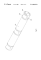
- FIG. 8 is a view of the preferred embodiment of a header syringe.
- FIG. 9 is a view of the preferred embodiment of a syringe plunger
- FIG. 10 is a view of the preferred reactor block latch mechanism, with the reactor block and all but one vessel hidden.
- FIG. 11 is a view of the preferred reactor block latch mechanism.
- FIG. 12 is a detail of the preferred latch drum.
- FIG. 13 illustrates an alternate embodiment of reactor vessel seals utilizing an inert “taper seal sheet” which is flared by pressing onto a conical protrusion in the insulator block.
- FIG. 14 illustrates an alternate embodiment of reactor vessels seals utilizing a composite seal made up of an o-ring fitted onto an inert spool.
- FIG. 15 illustrates an alternate embodiment of individual insulator orifices as seals, which snap into the reactor vessels, and engage the header vessels with a taper fit.
- FIG. 16 shows a detail of the preferred embodiment of an orifice insert used to separate the reactor vessels from the header vessels, which is pressed into a carrier plate.
- FIG. 17 shows a front view of the preferred embodiment of the drive system with the reactor block and the header block.
- FIG. 18 shows a back view of the preferred drive system.
- FIG. 19 shows the preferred embodiment of a mixing system and inert atmosphere enclosure for the continuous feed parallel reactors, in which two reactors and drive systems are mounted to rotary tables.
- FIG. 20 shows the preferred embodiment of a liquid handling robot used to dispense diverse chemicals into the header and reactor vessels.
- FIG. 21 shows the preferred method of filling and assembling the header and reactor vessels.
- FIG. 22 shows an alternate embodiment of the continuous feed parallel reactor in which the reactor vessel volume as well as the header vessel volume is variable.
- FIG. 23 shows an alternate embodiment of the continuous feed parallel reactor in which a third storage tank is added to the system, allowing materials to be removed from the reactor during or after a reaction.
- the present invention provides an apparatus and method for carrying out multiple reactions in parallel. It is especially useful for synthesizing and/or screening combinatorial libraries.
- header barrel is used to describe the container that holds the one or more reactants that are fed into the reactor from the sources in the header.
- barrel is not intended to be limiting and a header barrel can take any convenient form including a vessel, tank, barrel, pipe, vial, syringe or other form of container.
- storage tank is used to describe the container that holds the material that exits the reactor.
- tank is not intended to be limiting and a storage tank can take any convenient form including a vessel, tank, barrel, pipe, vial, syringe or other form of container.
- FIG. 1 shows a constant volume embodiment of a parallel reactor system 10 .
- the system 10 comprises a reactor block 100 and a header block 200 having sandwiched between them a plate 300 that holds the transfer lines 302 allowing for fluid communication between the reactors 102 in the reactor block 100 and the header barrels 202 in the header block 200 .
- the system 10 additionally comprises a plunger plate 400 for pressing on plungers 402 that form the top of the header barrels 202 to feed reactant(s) through the transfer line 302 into the reactor vessels 102 .
- the system additionally comprises a drive system (not shown in FIG. 1) for driving the plungers (i.e., the plunger plate).
- reactants, catalysts, initiators, solvents, scavengers, etc. are loaded into the reactor vessels 102 leaving some headspace.
- Reactant(s) to be added to the reactor vessel 102 during the reaction is loaded into the header barrels 202 at the opposite end from the plungers 402 .
- the vessels 102 are placed in the wells 104 of the reactor block 100 .
- the plate 300 comprising the transfer lines 302 and the seals 320 & 340 is then secured to the header block so that a single transfer line 302 communicates with a single header barrel 202 and so that each header barrel is sealed to the outside except for the transfer line.
- the plate is also secured to the reactor block 100 so that a single transfer line 302 communicates with a single reactor vessel 102 and so that each reactor vessel 102 is sealed to the outside except for the transfer line.
- the reaction may begin when all the components are added, but preferably the reaction beginning is controlled, for example by supplying heat to the reaction vessels via a temperature control system 900 in the reactor block (which is discussed below).
- the drive system forces the plungers down thereby feeding reactant(s) into the reaction vessel from the header barrel. This compresses the contents in the reactor vessels. Sufficient headspace in the reactor vessels allows that gas to compress with the pressure increase in the system is easily withstood by the sealing means.
- the reactions may be mixed by the addition of mixing ball to each reactor vessel and placing the entire system 10 on a rocker platform, which allows the mixing balls to tumble through the contents of the reactor.
- the transfer means for transferring the liquid reactant(s) from the header barrel(s) to the reactor vessels, can be controlled so that a desired rate of reactant feed into the reactor vessels is met.
- the motor is controlled so that the drive system drives the plungers down feeding at a desired volume per unit time.
- the reactants are fed into the reactor so that the time required for substantially complete feeding of the reactant(s) into the reactor from the header is on the time frame of typical industrial processes. This time is in the range of from about 0.5 hours to about 24 hours, preferably in the range of from 1-12 hours.
- the kinetics of the chemistry is used to select the desired feed rate, with fast chemistry allowing for faster feed rates and vice versa.
- the feed time may be in the range of from about 1 minute to about 48 hours.
- FIG. 2 An alternative embodiment is shown in FIG. 2, where the reactor system 10 comprises a reactor block 100 having a plurality of reactor wells 104 .
- a transfer line 302 allows for fluid communication between a pump 20 and each well 104 .
- the pump 20 has a feed line 22 for obtaining reactant from the header barrel 202 .
- the reactor vessels are individually sealable (e.g., with a screw cap or other sealing means) to allow for a constant volume reaction.
- a check valve may be added to avoid back diffusion into the transfer line.
- the method of feeding the reactant(s) into the reactor is a pump. There may be more than one pump, e.g., 2, 3 or more pumps, up to the number of reactors. Suitable pumps include syringe pumps and gear pumps.
- a plate (not shown) can connect the transfer lines 302 to each reactor vessel as well as seal each reactor vessel.
- a plate 300 such as discussed below could be used for this purpose.
- Another alternative is to provide valves in the transfer lines 302 , to prevent reverse flow of reagents from the reactor to the header, or to direct flow from the header barrel in a rapid serial fashion to each of the reactor vessels, using a single flow meter or pump.
- a preferred reactor block 100 is shown in a cutaway view in detail in FIG. 3 .
- the reactor block 100 includes removable vessels 102 for receiving reactants, catalysts, initiators, solvents, etc.
- Wells 104 formed into a reactor block 100 contain the vessels 102 .
- the wells 104 can serve as reactor vessels, in one embodiment, with the wells being disposed in the reactor block.
- removable vessels 102 are used inside the wells because of several advantages. For example, following reaction and preliminary testing (e.g., screening), one can remove a subset of vessels 102 from the reactor block 106 for further in-depth characterization.
- removable vessels 102 one can also select vessels 102 made of material appropriate for a given set of reactants, products, and reaction conditions.
- the removable reactor vessels 104 can be made of any appropriate material that is inert to the reaction being conducted, including plastic, glass, etc.
- the reactor vessels are glass because glass vessels of varying size and shape are commercially available and amenable to various sealing methods.
- the vessels 104 are shown as cylindrical in shape, but any convenient shape can be employed, including square, rectangular, etc.
- each of the removable vessels 102 preferably contacts the bottom of the well 104 .
- the bottom of the well 104 is the top of a spring pre-tensioner 106 that is surrounded by a spring 108 and bolted to the bottom 110 of the reactor block 100 with a nut 112 .
- a detail of this reactor spring 105 assembly is shown in FIG. 4 .
- the spring 108 is preloaded with a desired amount of compression. There are two related functions this assembly performs: (1) allowing for consistent sealing of a plurality of reactor vessels and (2) accounting for variances in the height of the reactor vessels. As shown in FIG. 3, the bottom of the reactor vessels 102 contact the top of the spring pre-tensioners 106 .
- FIG. 5 is a graph showing a preferred method in which a particular spring at a particular preload changes the sealing force very little over a limited deflection, accounting for variations in reactor vessel height, and accounting for differential thermal expansion. Therefore, different spring tensions allow for different pressures.
- the pressure in the reactor vessel can thus be adjusted for a particular reaction.
- the reaction pressure can vary from atmospheric to about 1000 psi. It is possible to have a negative pressure in the system, for example by loading heated starting materials or reactant(s) followed by sealing the system and then cooling or for example by removing contents from the reactor without adding reactants from the header (in the continuous embodiment discussed below).
- the reactor spring assembly 105 allows for a variation in height in the reactor vessels with maintaining the same amount of pressure in each reactor. Because commercially available replacement reactor vessels have some height variation, this system accounts for that variation.
- this preferred embodiment employs a single spring for each well, in other embodiments, a single spring can be used for a plurality of reactor wells and vessels.
- a possible disadvantage is that sealing may not be sufficient; however, the number of wells, the uniformity of the vessels as well as the reaction being studied (e.g., a low-pressure reaction) may allow for a single spring system to sufficiently seal the reactors.
- the reactor block contains any desired number of wells.
- the embodiment shown in FIG. 1 has 96 wells. This embodiment is shown more clearly in FIG. 6, where the top of the reactor block 100 is shown in FIG. 6A having a plurality of wells 104 .
- the bottom of the reactor block 100 is shown in FIG. 6B, showing the reactor bottom 110 having a plurality of holes 114 for receiving the spring pre-tensioners 106 (see FIG. 4 for the detail).
- FIG. 7 Another embodiment is shown in FIG. 7, where three reactor vessels 102 are shown, without the reactor spring system just discussed. In the embodiment in FIG. 7, sealing and variation in reactor vessel height is accounted for by tightening the plate 300 to the reactor block 100 with bolts, clips, claimps or other fastening mechanisms known to those of skill in the art.
- the overall size of the reactor block and the volume of the reactor vessels influence the number of wells. Thus, if a larger volume reaction is desired, typically a fewer number of wells are in the reactor block. Preferably, there are at least 6 wells, more preferably at least 15 wells and even more preferably at least 48 wells. In the most preferred embodiment there are at least 96 wells.
- a 96 well reactor block may correspond to a standard microtiter plate format, namely an 8 by 12 array of wells on 9 mm spacing and is preferred due to its high throughput capacity and standardization of equipment.
- the reactor block also contains a temperature control system as described below.
- FIG. 3 shows a cutaway, detailed view of the bottom portion of the preferred header block.
- the header block 200 includes removable barrels 202 for receiving reactant(s) that are to be fed into the reactor during the reaction.
- header wells 204 formed into a header block 200 contain the barrels 202 .
- the header wells 204 can serve as barrels, removable barrels 202 provide several advantages. For example, they prevent fouling or contamination of the header block, requiring less cleanup following a reaction.
- removable barrels 202 one can also select barrels 202 made of a material appropriate for a given set of reactants and reaction conditions.
- the barrels can be obtained with very high dimensional precision, improving the seal between barrel 202 and plunger 402 . If necessary, the barrels 202 can be discarded after use. This can lower system costs and ensure compatibility with standardized sample preparation and testing equipment by designing the header block 200 to accommodate commercially available vessels/barrels.
- the header block contains the same number of wells as the reactor block, in a matching configuration.
- the barrels 202 can be made of any material that is inert to the reaction, solvents, reactants, etc., including glass, plastic, etc.
- the barrels are made of glass, for the same reasons that the reactor vessels are preferably made of glass.
- the removable barrels 202 are shown in detail in FIG. 8 .
- the barrel 202 may include a collar 206 on the outside of the barrel and near one end of the barrel. This collar keeps the spring compressed, performing the same function as the spring pre-tensioners and nut in the reactor block.
- the end of the barrel opposite the collar is flared to match the diameter of a header spring 210 , shown in FIG. 1 .
- the header spring assembly 208 contains a spring 210 that forces the barrel 202 into the header seal 340 .
- the header barrel is sized to match the diameter of the header spring 210 .
- the header spring is preloaded in compression, similarly to the reactor spring 108 and for the same reasons.
- the preloaded compression force on the spring comes from appropriate sizing of the length of the header barrel and the spring, as well as a header block top plate 212 that compresses the spring to the appropriate preloaded force.
- the header block top plate 212 may fit into a broader section of the top of the header block or may be the top of the header block (not shown).
- the header spring assembly performs: (1) allowing for consistent sealing of a plurality of header barrels and (2) accounting for variances in the height of the header barrels, differential thermal expansion. As shown in FIG. 1, the top of the header barrels 202 contact the bottom of the header spring 210 .
- the bottom of the header barrel 202 contacts a header seal 340 associated with the plate 300 , which is discussed in detail below.
- the header spring 210 provides the force to seal the barrel to the header seal 340 .
- the amount of compression in the spring and the stiffness of the spring determine the amount of force pressing the bottom of the header barrel into the header seal. Therefore, different spring tensions allow for different pressures. The pressure in the header barrel can thus be adjusted for a particular reaction.
- header spring assembly 208 allows for a variation in height in the header barrels with maintaining the same amount of pressure in each barrel. Because commercially available replacement header barrels have some height variation, this system accounts for that variation.
- this preferred embodiment employs a single header spring for each header well, in other embodiments, a single spring can be used for a plurality of header wells and barrels.
- a possible disadvantage is that sealing may not be sufficient; however, the number of wells, the uniformity of the barrels as well as the reaction being studied (e.g., a low-pressure reaction) may allow for a single spring system to sufficiently seal the barrels.
- a plunger 402 runs through the center of the header spring assembly 208 to inject reactant(s) from the header into the reactor.
- the plunger is the transfer method.
- the top of the plunger 402 is attached to a plunger plate 400 , which in turn is associated with the drive system for driving the plungers forward to inject reactant(s) into the reactor from the header.
- a detail of the plunger is shown in FIG. 9 .
- the top of the plunger 404 comprises a head that attaches to the plunger plate. Attachment can be by any method known to those of skill in the art.
- a preferred method of attaching the plunger top 404 to the plunger plate 400 is via a detachable method, such as by screwing the top of the plunger into the plunger plate.
- a detachable attachment is preferred because it allows for plungers to be removed from the plunger plate for replacement or cleaning.
- Another preferred feature of the plunger is a swivel joint 406 between the plunger rod 408 and the plunger top 404 .
- the swivel joint allows for some flexibility in the connection between the plunger and plunger plate while the plunger plate 400 is being pressed by the drive system.
- the plunger can be made of any suitably rigid material, such as metal.
- the bottom portion of the plunger 402 has a plunger tip 410 , shown in FIG. 9 in detail and shown in context in FIG. 1 .
- the plunger tip 410 contacts the reactant(s) and forces them into the reactor from the header as the plunger moves forward.
- the plunger tip is fitted over the end of the plunger rod 408 with sufficient adhesion so that the tip does not come off of the rod when the plunger is moved backward.
- the tip may be made of plastic that is heat shrunk onto the end of the plunger rod or it may seal against O-rings between the rod shaft and the plunger tip, when pressed into barrel 202 .
- the plunger tip 410 contains one large raised portion 411 and one or more small raised portions 412 (shown in FIG. 9) for sealing the contents of the header barrel. As the plunger is moved forward, the raised portions 411 , 412 contact the inside of the header barrel 202 forming a seal. The size and number of raised portions will depend on the pressure in the system, but preferably there are from 2-10 smaller raised portions on the plunger tip.
- the plunger tip 410 is made of a material that is inert to the reaction, solvents, reactants, etc., including plastic, etc. Preferably, the tip is made of plastic, such as PTFE.
- a plate 300 resides between the reactor block 100 and header block 200 .
- the plate 300 is secured to both blocks and includes the transfer lines 302 , the reactor seal 320 and the header seal 340 .
- the plate can also function as either a heat conductor or insulator. As discussed below, heat may play an important roll in the reactions that can be run in this reactor system. In some circumstances, the heat that is applied to the reactors will be conducted to the reactant(s) that reside in the header. In other cases, the heat applied to the reactors is not to be conducted to the header barrels. Thus, the plate can be designed to either conduct heat or not. For most reactions, heat should be applied only to the reactor and not to the reactant(s) waiting in the header barrels for injection into the reactors. Thus typically, the plate will have thermal insulating properties and be made from a material that is a poor conductor of heat, such as stainless steel, ceramic, or plastic.
- the plate 300 is attached to each of the reactor block 100 and header block 200 via a method of attachment that seals each to the plate with sufficient force to withstand the pressure of the reaction occurring in the reaction vessels.
- the method of attachment can be by bolting, clamping, clipping or other removable fasteners.
- the plate 300 is bolted between the reactor block 100 and the header block 200 .
- a preferred method for attaching the plate 300 to the reactor block and header block is via a latch mechanism 600 , shown in FIG. 10 .
- the latch mechanism 600 provides several advantages for combinatorial research.
- the latch mechanism 600 translates a single input motion to two counter-rotating drums 604 , which pull the plate carrying the transfer lines 302 orthogonally onto the reactor vessel 102 and header barrel 202 lips without tilting the vessels or barrels, assuring little or no spillage from the reactor vessels or header barrels, and assuring uniform application of sealing force. Sealing of each reactor vessel and header barrel is simultaneous with the latch mechanism 600 .
- the latch mechanism 600 includes one or more, preferably a plurality of, latch pins 602 that are fixed to the plate 300 .
- the latch pins 602 engage a latch drum 604 , which rotates pulling the latch pins 602 down thereby securing the plate to the reactor block and header block. The plate in most instances is locked to the block.
- the latch mechanism 600 which has been fabricated for sealing an array of vessels supported by the reactor spring assembly 105 in the reactor block with each latch pin 602 having a hemispherical ball-tip 603 on the end of the latch pin 602 .
- the latch drum 604 has a hemispherical socket 605 cut into its perimeter which mates with the ball-tip 603 .
- a relief 607 is provided in the latch drum 604 so that when the drum is in open position, the ball tip 603 can be inserted into the reactor block past the latch drum 604 .
- the latch drum 604 is then rotated to its closed position (approximately one-quarter turn) so that the socket 605 mates with the ball tip 603 and pulling the latch pin 602 down.
- Each end 606 of the latch drum 604 extends outward and beyond the edge of the end row of reactor vessels or header barrels to a latch arm 608 , shown in FIG. 11 .
- the latch drum arm 608 is pivotally attached to an over-center link 610 , which in turn is attached to a latch gear 612 that is rotated by an input shaft 614 and pinion 616 .
- the input shaft is rotated either manually or automatically.
- the pinion 616 engages the first latch gear 612 a , which engages the second latch gear 612 b thereby simultaneously moving the over-center links 610 .
- the over-center links 610 rotate the latch arms 608 , which rotate the latch drums 604 , securing the latch pins 602 and thus securing the plate 300 to the reactor block 100 .
- latch drums 604 there are preferably at least two latch drums 604 in each of the reactor block and header block, on opposite sides of the block.
- the latch gears 612 a , 612 b allow the two symmetrical latch drums 604 to counter-rotate fully sealing both the vessels and barrels.
- the latch mechanism completes a four-bar mechanism with the gears 612 a , 612 b , drum arm 608 , and reactor block.
- This four-bar mechanism is optimized to be quick-acting, with a rapidly increasing mechanical advantage as the mechanism is actuated to a closed position, and a corresponding decrease in drum rotation for input gear rotation.
- this quick-acting movement opens or closes the drums 604 rapidly, slowing down for the final portion of the stroke when the preloaded springs 108 become engaged, best seen in FIG. 10 .
- the over-center link 610 goes over-center by a few degrees. This provides a locked position requiring no input force to hold the mechanism closed.
- the input shaft 614 is simply rotated in the reverse direction past this over-center position, and the springs 108 push the mechanism open.
- latching mechanism 600 is shown for the reactor block, the same mechanism is in the header block 200 for attaching the plate 300 to the header block 200 .
- the latch mechanism 600 operates in the header block in the same fashion as in the reactor block.
- Other embodiments of this latch mechanism could be accomplished via eccentric cams, worm gears or other simple mechanisms.
- the reactor vessels are sealed to the outside except for the transfer line and the header barrels are sealed to the outside also except for the transfer line.
- These are pressure tight seals that withstand pressures up to 1000 psi, depending on the sealing material and method chosen.
- the preferred embodiment of this closed system has three seals, but could have more seals in other embodiments.
- the system in FIG. 2 has four seals, two seals where the feed line joins the barrel 202 to the pump 20 and two seals where the transfer line 302 joins the pump to the wells 104 .
- the three seals are at the plunger tip 410 sealed to the inside of the header barrel 202 , the header barrel 202 lip sealed to the plate 300 and the reactor vessel 102 lip sealed to the plate 300 .
- the first of these seals is discussed above.
- the header seal 340 is the seal between a lip of the header barrel 202 lip and the plate 300 .
- the reactor seal 320 is the seal between a lip of the reactor vessel 102 and the plate 300 .
- the preferred sealing method has a lip of the reactor vessel or header barrel forced into a material that receives the lip. This sealing method has several embodiments.
- FIG. 3 The most preferred sealing method is shown in FIG. 3 .
- the reactor seal 320 there is a gasket 322 that fits over one end of the transfer line 302 , with the gasket 322 fitting snuggly to the outer diameter of the transfer line 302 and extending beyond the diameter of the reactor vessel 102 .
- the gasket 322 is associated with the plate 300 in that the gasket is attached to the plate without allowing substantial leakage between the gasket and the plate. Although some leakage may occur, it is kept to a minimum by tightening the attachment means, which attaches the reactor block 100 to the plate 300 .
- the gasket 322 is preferably a continuous sheet that fits over each transfer line for each reactor vessel 102 in the array of wells and vessels that comprise the reactor block.
- a continuous sheet has the advantage of ensuring that the diameter of the reactor vessels 102 does not extend beyond the edge of the gasket 322 , and can be replaced for all vessels simultaneously.
- the properties of the gasket can be selected to account for different sealing pressures, with the seal withstanding a pressure in the reactor vessel of up to about 1000 psi without leaking.
- the gasket material should be inert to the reaction conditions and chemicals in the reaction.
- the gasket can be made of perfluoroelastomer, such as Kalrez or some other chemically resistent elastomer. Most preferably the gasket is made from PTFE (Teflon) encapsulated silicone rubber.
- header gasket 342 that fits over the other end of the transfer line 302 , with the header gasket 342 fitting snuggly to the outer diameter of the transfer line 302 and extending beyond the diameter of the header barrel 202 .
- the header gasket 342 gives to accept the lip of the barrel 202 while the end of the transfer line 302 extends into the header barrel.
- the header gasket 342 is preferably a continuous sheet that fits over each transfer line for each header barrel 202 in the array of wells and barrels that comprise the header block.
- a continuous sheet has the advantage of ensuring that the diameter of the header barrels 202 do not extend beyond the edge of the header gasket 342 .
- the properties of the gasket can be selected to account for different sealing pressures, with the seal withstanding a pressure in the header barrel of up to about 1000 psi without leaking.
- the gasket material should be inert to the reaction conditions and chemicals in the reaction (e.g., the reactant(s)).
- the gasket can be made of a perfluoroelastomer such as Kalrez or some other chemically resistent elastomer. Most preferably the gasket is made from PTFE (Teflon) encapsulated silicone rubber.
- the reactor seal 320 includes a rubber reactor gasket spring 322 that fits into a channel 304 that is cut into the plate 300 .
- a feature of the channel 304 is a tapered portion 306 for receiving the lip of the reactor vessel 102 .
- a second inert gasket 324 is in between the reactor gasket spring 322 and the reactor vessel 102 to provide additional inert properties with respect to the reaction conditions and chemicals in the reaction being studied.
- this same seal could be used for the header seal.
- the properties of the gasket and second gasket can be selected to account for different sealing pressures, with the seal withstanding a pressure in the reactor of up to about 1000 psi without leaking.
- the gasket material should be inert to the reaction conditions and chemicals in the reaction (e.g., the reactant(s)).
- the gasket can be made of silicone rubber. Most preferably the gasket is made from either Kalrez or some other chemically resistant elastomer.
- the second gasket can be made of PTFE (Teflon).
- FIG. 14 Yet another sealing embodiment is shown in FIG. 14 .
- An o-ring 326 rests inside a spool 328 , which is placed at the end of the reactor vessel 102 .
- the transfer line 302 feeds reactant through the center of the spool.
- the spool 328 rests inside a channel 304 cut into plate 300 that is designed to accommodate the shape of the spool 328 .
- the spool is made of plastic and more preferably PTFE (Teflon).
- the o-ring may be made of a standard material such as silicone rubber. This seal has particularly good thermal insulating properties.
- FIG. 14 also shows a mixing ball 370 in the barrel 202 .
- the reactor seal 320 comprises a channel 304 cut into the plate 300 for receiving the reactor vessel 102 lip.
- the plate 300 is an individual piece for each vessel, and preferably a plastic material so as not to damage the reactor vessels.
- the inner surface of the reactor vessel snaps into the tapered portion 306 of the channel 304 via a raised portion 308 .
- the collar 206 of the header barrel 202 extends over a tapered tip 310 , which fits over the tapered portion 306 of the channel 304 on the header side of the plate 300 .
- This system also snaps the header barrel to the plate to form the seal.
- the wetted portions of this seal embodiment are inert to the reaction conditions and chemicals in the reaction.
- FIG. 15 also shows mixing balls 370 in the reactor vessel 102 and header barrel 202 .
- the transfer lines function to transfer reactant(s) from the header into the reactor. They are preferably inert to the reactants being studied. Also preferably, the transfer lines are sized (either in length or diameter) so that the injection velocity into the reactor from the barrel is higher than the back diffusion velocity from the reactor into the barrel. Preferably, the amount of diffusion of reaction components from the reactor to the header is limited. For example if a sufficiently small diameter is chosen for the transfer line, chemicals that are reacting or are needed in the reaction (such as solvent, scavengers, etc.) will remain in the reactor and not diffuse to the header.
- the transfer lines 302 can be tubing or conduit as shown in FIG. 2 .
- the transfer lines 302 can be channels in plate 300 as shown in FIGS. 13, 14 and 15 .
- the transfer lines 302 are inert inserts that fit into a hole in the plate 300 .
- a detail of the preferred transfer line 302 is shown in FIG. 16, where the transfer line includes a line 312 running the length of the insert that allows the communication of fluids from the header to the reactor.
- a flange 314 At one end of the insert is a flange 314 that holds the insert in place and prevents it from moving. This flange is preferably placed at the reactor side of the plate 300 (as shown in detail in FIG. 3 ).
- the line 312 is shown as larger in diameter at the header side than at the reactor side, which is preferred to limit diffusion of chemicals from the reactor to the header.
- Another feature of the inserts is a channel 316 (also shown in FIG. 16 ), transverse to the axis of the transfer line 312 , in each end of the insert to allow for the flow of reactant in the presence of a mixing ball so that the mixing ball cannot block the line 312 .
- the preferred drive system is shown in FIGS. 17 and 18.
- the reactor block 100 is shown with a plurality of reactor vessels 102 that are sealed to the plate 300 , which in turn is sealed to the reactor block 200 .
- a plurality of plungers 402 is shown extending into the header block 200 from the plunger plate 400 .
- the entire system, from bottom of the reactor block 100 to the top of the plunger plate 400 is associated with the drive system 500 , which functions to force the plunger plate down so that the plungers feed reactant(s) from the header barrels to the reactor vessels.
- the drive system 500 could simply be a weight of sufficient mass that drives the plunger plate down due to gravity. However, such a system could not function in alternative embodiments where the entire system is placed on a rocking plate for mixing.
- the preferred drive system comprises a frame 502 having a center support 504 with a movable carriage 506 extending therefrom at about a right angle at one end and a fixed arm 508 extending therefrom also at about a right angle at the other end.
- the center support 504 is shown as a plate, however, other designs will be evident to those of skill in the art, including a series of two or more rails.
- the carriage 506 freely moves along the length of the center support 504 on one or more rails 510 , which may be fixedly attached to the center support 504 and attached to the carriage via a clamp and bearings (not shown) to allow smooth movement.
- the rails may be attached to the back of the carriage, with the clamp and bearings being fixedly attached to the center support. It is preferable to reduce friction in the movement of the carriage 506 with respect to the center support 504 .
- the method of attachment is not critical to the invention and those of skill in the art may use other reduced friction types of attachments.
- the carriage 506 comprises a flat plate 512 extending approximately perpendicularly from the rails 510 with the bottom of the flat plate 512 contacting the plunger plate 400 .
- the carriage 506 could comprise this plate alone, however for higher pressures in the reaction system (e.g., reactor vessels, header barrels and transfer lines), it is preferred that the carriage be able to withstand high forces and the embodiment shown in FIG. 17 exemplifies such a carriage 506 .
- the carriage 506 in FIG. 17 comprises a flat plate 512 connected at each side to carriage support plates 514 .
- the carriage flat plate 512 and carriage support plates 514 are attached to a carriage back plate 516 , which in turn is connected to the clamp and bearings for movement along the rails 510 .
- This preferred carriage 506 design is capable of driving 96 plungers forward without deformation.
- the carriage design is not critical to the invention and other carriage designs will be apparent to those of skill in the art.
- the back of the preferred drive system 500 is shown in FIG. 18 .
- the back of the carriage 506 extends through the center support 504 and is attached to a lead screw 518 .
- the lead screw 518 is attached by supports 520 to the center support 504 , such that the lead screw 518 may rotate within supports 520 .
- the lead screw 518 is threaded with matching threads on the back of the carriage 506 so that when the lead screw rotates, the carriage 506 moves up and down along the rails 510 .
- a toothed belt 522 joins one end of the lead screw 518 to a gear head 524 .
- the belt 522 need not be toothed, but slippage is preferably avoided with such a belt.
- a motor 526 rotates the gear head 524 .
- the motor 526 may be either AC or DC driven and is preferably a commercially available gear motor, such as Industrial Devices model G23PI-S23-0100 or equivalents.
- Other features of the preferred drive system shown in FIG. 18 include the belt tensioner 532 for maintaining the tension on belt 522 to further avoid slippage.
- a motor amplifier 528 for converting commands to appropriate electrical signals for the motor, such as Applied Motion Products model PD2035 or equivalents.
- This preferred drive system 500 operates by the motor 526 turning gear head 524 and gear 530 , which move the belt 522 and which in turn rotates the lead screw 518 , leading to movement of the carriage.
- This system is preferred because it is strong, compact and can operate either vertically or horizontally or at other angles.
- the drive system with reactor system in place can be placed on a rocking platform or other oscillating mechanism for mixing the reaction and reactant(s) with a mixing ball.
- mixing balls would be ineffective and another mixing method would be employed, such as magnet stir bars.
- reaction products can be influenced by mixing intensity, a uniform mixing rate ensures that any differences in products does not result from mixing variations.
- mixing balls are preferred with this invention. See commonly assigned U.S. patent application Ser. No. 09/177,170 filed Oct. 22, 1998 (having attorney docket number 65304-044), which is herein incorporated by reference, for alternative mixing embodiments that are also useful in this invention.
- the chamber 700 may be evacuated or filled with a suitable gas, such as an inert gas like nitrogen or argon.
- a suitable gas such as an inert gas like nitrogen or argon.
- This chamber is most usefully a glove box (or dry box), such as those sold commercially by Vacuum Atmospheres, Inc.
- the chamber 700 may be used only during the loading of starting materials into the vessels 102 and/or barrels 202 to minimize contamination during sample preparation, for example, to prevent poisoning of oxygen sensitive catalysts.
- FIG. 19 Another feature of FIG. 19 that should be noted is the rotating plate 710 pivotally mounted on a support platform 720 and driven by a motor (not shown).
- a motor not shown
- FIG. 19 shows the rotating plate 710 with the entire reactor system and drive system attached. The rotating plate turns at a predetermined rate to allow the mixing balls in the reactor vessels and/or header barrels to mix the contents thereof.
- the reactants are liquids (but they may be one or more gases).
- an automated liquid handling system may be employed to handle the liquid.
- a robotic liquid handling system 800 is may be used to load vessels and barrels with starting materials.
- the robotic system 800 includes a probe 801 that dispenses measured amounts of liquids into each of the vessels and/or barrels.
- the robotic system 800 manipulates the probe 801 using a 3-axis translation system 802 .
- the probe 801 is connected to one or more sources 803 of liquid reagents through flexible tubing 804 .
- Pumps 805 which are located along the flexible tubing 804 , are used to transfer liquid reagents from the sources 803 to the probe 801 .
- Suitable pumps 805 include peristaltic pumps and syringe pumps.
- a multi-port valve 806 located downstream of the pumps 805 selects which liquid reagent from the sources 803 is sent to the probe 801 for dispensing in the vessels and/or barrels.
- FIG. 20 shows a reactor block 100 in place for loading, but a series of vessels or barrels or a header block could also have been shown.
- the robotic liquid handling system 800 is controlled by a processor 807 .
- the user first supplies the processor 807 with operating parameters using a software interface.
- Typical operating parameters include the coordinates of the vessels and the initial compositions of the reaction mixtures in individual vessels.
- the initial compositions can be specified as lists of liquid reagents from each of the sources 803 , or as incremental additions of various liquid reagents relative to particular vessels.
- the robotic handling system may dispense reactant into the header barrels. See commonly assigned U.S. patent application Ser. No. 09/174,986, filed Oct. 19, 1998 (having attorney docket no.
- the robotic handling system may be used in a methodology shown in FIG. 21 .
- FIG. 21A liquid reactants are added to both the reactor vessel 102 and the header barrel 202 (shown with the plunger tip 410 ).
- FIG. 21B is next where the plate 300 having transfer lines 302 with orifices 312 is attached to the header barrels 202 forming the header seal and the plunger 402 is optionally moved forward to expel gas from the header barrel 202 .
- the header barrels 202 are inverted to connect the plate to the reactor vessels 102 forming the reactor seal.
- the reactant(s) in the header do not spill out because of surface tension given the size of the orifice 312 .
- This reactor system is then put into the drive system and then entire assembly is put onto a rocker platform 30 , shown in FIG. 21D, that rocks back and forth over a pivot point 32 .
- FIG. 22 shows another embodiment of this invention, which will build less pressure due to compression of the headspace during reaction.
- the header barrel 202 is also sealed to the plate 300 .
- the header barrel 202 has a plunger 402 that controls the volume of the header barrel 202 by moving forward and backward as controlled by a drive system 500 .
- the reactor vessel 102 also includes a plunger 402 ′ that controls the volume of the reactor vessel 102 by moving froward and backward as controlled by a reactor drive system 500 ′.
- the reactor drive system 500 ′ is similar to or identical to the header drive system 500 , which has been discussed in detail.
- one end of the plungers 402 , 402 ′ is attached to a plunger plate (not shown) that may be part of or separate from a carriage 506 , 506 ′.
- the carriage 506 , 506 ′ is moved forward and back by a lead screw 518 , 518 ′, which is rotated by a motor 526 , 526 ′.
- the header barrels 202 and reactor vessels 102 are sealed at the plunger 402 , 402 ′ end by contact of the plunger tip 410 , 410 ′ to the inside of the barrel or vessel, respectively.
- the entire system is built on a support 550 , including a support for the plate 300 .
- each plunger runs through a reactor vessel and has a tip 410 ′ that forms a seal with the inside of the reactor vessel, such that when the reactor plunger 410 ′ is moved backward the volume of the reactor vessel is increased. When the reactor plunger is moved forward, the reactor vessel volume is decreased.
- the reactor plungers each have a top attached to another plunger plate that moves the plurality of reactor plungers simultaneously, as described above for the header plungers.
- the liquids and gasses are added to the vessels 102 and barrels 202 along with mixing balls or other mixing parts (discussed above) either manually or in an automated fashion.
- the vessels and barrels are then sealed to the plate 300 and connected to the drive system 500 , 500 ′.
- the entire system may then be placed on rocking plate or a rotating plate (such as shown in FIG. 19) for mixing during reaction.
- the sum of reactor and header volume may be kept constant by moving the reactor plunger 402 ′ backward at the same speed that the header plunger 402 is moved forward.
- this embodiment allows operation at constant available reactor volume by moving only the header plunger 402 , as discussed above.
- FIG. 22 there can be any number of matched vessels and headers such as discussed above for the constant volume embodiment discussed above.
- FIG. 23 shows the embodiment of a continuous reactor system.
- one side of the reactor vessel 102 is connected to the header barrel 202 via a transfer line 302 .
- the reactor vessel 102 is sealed to plate 300 .
- a holding tank 150 also called a storage tank
- second transfer line 152 is connected to other end of the reactor vessel 102 via a second transfer line 152 that is contained in a second plate 154 .
- the various embodiments for the second transfer line and second plate can be any of those discussed above for the plate and transfer line(s).
- the reactor vessel is constant available volume, while both the header barrel 202 and the holding tank 150 are variable volume, with plungers 402 , 402 ′′ driven by independent carriages 506 , 506 ′′.
- the numbered parts are the same as discussed above for similarly numbered parts.
- the contents of the header barrel 202 are pushed into the reactor vessel 102 .
- the holding tank which may be filled, with chemicals that quench the reaction.
- the residence time in the reaction vessel may be varied to suit a particular type of reaction.
- the sum of reactor, holding tank and header volume may be kept constant by moving the holding tank plunger 402 ′′ backward at the same speed that the header barrel plunger 402 is moved forward.
- a plurality of second transfer lines corresponding and sealed to the plurality of reactor vessels is also corresponding and sealed to a plurality of holding tanks.
- a second transfer means is provided associated the plurality of holding tanks and the second transfer means is adapted to remove at least some of the contents of the plurality of reactor vessels through the second transfer lines into the holding tanks.
- the second transfer means may be a pump and the second transfer lines may be tubing.
- the second transfer means comprises a plurality of plungers 402 ′′, with each plunger running through a holding tank and with each of plunger having a tip 410 ′′ that forms a seal with the inside of the holding tank, such that when the plunger is moved backward contents are removed from the reactor vessel through the second transfer line and into the holding tank.
- each plunger has a top that is attached to a second plunger plate, such that all plungers in the plurality move simultaneously when the plunger plate is moved. The second plunger plate is moved by the second drive system 500 ′′.
- the reactor and header blocks may be split up into modules, each containing a certain number of wells and vessels for a given number of reactions.
- the use of modules offers several advantages over a monolithic block. For example, the size of the block can be easily adjusted depending on the number of reactants or the size of the combinatorial library. Also, relatively small modules are easier to handle, transport, and fabricate than a single, large block. A damaged module can be quickly replaced by a spare module, which minimizes repair costs and downtime. Finally, the use of modules improves control over reaction parameters. For instance, the plunger plate of different modules may be driven forward at different rates or the temperature or pressure of each of the vessels can be varied between modules. Multiple header vessels may feed into each reactor vessel, and multiple holding vessels may remove contents from each reactor vessel.
- the wells, reactor vessels, header barrels, storage tanks, etc. of this invention can be arranged and/or operated in a combinatorial fashion, that is, in rapid serial and/or parallel fashion, e.g., in a library or array format.
- each of the plurality of reactor vessels, header barrels, storage tanks, plungers, etc. can be the same or somehow different from the others in the array.
- Such differences can be compositional (such as having a composition that is different), a processing parameter (such as temperature, pressure, atmosphere composition, etc.) or other differences that those of skill in the art will recognize from a review of this specification.
- each member in the array is in a different reactor such that each reaction is isolated from the others.
- the array or library format typically comprises at least 6 different reactions, e.g., 6 different compositions being reacted or 6 different processing conditions (such as temperature or pressure). In other embodiments, there are at least 25 reactions, in still other embodiments, there are at least 48 or 96 or 124 or more different reactions. Because of the manner of forming combinatorial arrays, it may be that each compound, material or composition is not pure. Similarly, reaction conditions, processes, reactants, catalysts or solvents can be varied in a known manner using one or more arrays of the present invention.
- temperature can have a profound effect on structure and properties of reaction products.
- polymer structure and properties molecular weight, particle size, glass transition—can be influenced by reaction temperature.
- temperature control and monitoring of library members is often essential to making meaningful comparisons among members.
- temperature can be used as a screening criteria or can be used to calculate useful process and product variables. For instance, catalysts of exothermic reactions can be ranked based on peak reaction temperature, and temperature measurements can be used to compute rates of reaction and conversion.
- a temperature monitoring and control system which includes temperature sensors that are in thermal contact with individual vessels 102 .
- Suitable temperature sensors include jacketed or non-jacketed thermocouples (TC), resistance thermometric devices (RTD), and thermistors.
- the temperature sensors communicate with a temperature monitor, which converts signals received from the temperature sensors to a standard temperature scale.
- An optional processor receives temperature data from the temperature monitor.
- the processor performs calculations on the data, which may include wall corrections and simple comparisons between different vessels 102 , as well as controlling heaters in closed loop fashion.
- a dedicated temperature controller is provided, which communicates to an external computer. Thus, control functions and calculations may be performed in either place.
- each of the vessels and/or barrels can be maintained at the same temperature or at different temperatures during an experiment.
- the mixtures are then reacted at different temperatures to gauge the influence of temperature on catalyst performance (speed, selectivity).
- phase transitions melting range, glass transition temperature
- each of the vessels 102 of the reactor block 100 shown in FIGS. 1 or 3 are equipped with a heating element (such as cartridge heater) that fits into a channel 120 in the reactor block 100 .
- a heating element such as cartridge heater
- a similar channel 220 is in the header block 200 .
- each vessel has its own heating element between the vessel 102 and the top of the spring pre-tensioners 106 .
- a channel can run through the reactor block and/or header block that carries a heating fluid or cooling fluid, thereby heating or cooling the entire block to a desired temperature.
- a heating fluid or cooling fluid with an individual heater for each vessel and/or barrel provides complete control of temperature. Therefore the temperature of each reaction can range from about ⁇ 100° C. to about 300° C.
- temperature monitors are included to monitor the temperature of each vessel and/or barrel, so that the temperature of the vessels 102 or barrels 202 can be controlled independently.
- Other embodiments include placing the heating element and temperature sensor within the vessel or barrel, which results in more accurate temperature monitoring and control of the contents, and combining the temperature sensor and heating element in a single package.
- An example of a combined temperature sensor and heater is a thermistor, which can be used for both temperature monitoring and control because its resistance depends on temperature.
- Many different temperature monitoring and control embodiments are discussed in copending U.S. patent application Ser. No. 09/177,170, filed on Oct. 22, 1998 (having attorney docket no. 65403-044), which is incorporated herein by reference.
- Mixing variables such as the addition of mixing balls of various size with respect to the size of the reactor vessels and/or header barrels as well as the rate at which a rocker plate is rocked or a rotating plate is rotated or the composition or density of the mixing balls may influence the course of a reaction and therefore affect the properties of the reaction products.
- stirring bars stirring blade torque, rotation rate, and geometry, may affect the reaction, as described in copending U.S. patent application Ser. No. 09/177,170, filed on Oct. 22, 1998 (having attorney docket no. 65403-044), which is incorporated herein by reference.
- polymerization including coordination polymerizations, cationic polymerizations and free radical polymerizations.
- Polymerization is a preferred reaction for study in this mechanism and apparatus because of the variety of methods by which a polymerization reaction can be carried out.
- Semi-continuous and continuous processes also allow for efficient use of industrial reactor capacity, since the final concentration of products can be much higher than the instantaneous concentration of starting materials during the course of the reaction. Also, semi-continuous and continuous processes are readily controlled, because the rate of heat release is limited by the rate of reagent addition to the reactor. Semi-continuous and continuous processes can add the reagents more slowly than the rate of reaction, so that the instantaneous concentration of reagents is low throughout the process, but so that the concentration of product from the reactor is high.
- Reactions that benefit from this mode include cyclization reactions to form medium- and large-sized rings, reactions where one or more of the reagents is prone to unwanted self-reaction or polymerization, and catalytic processes where one or more reagents acts as an inhibitor to the catalyst.
- semi-continuous or continuous processes may allow for the production of more chemically uniform copolymers because the process can occur with a low concentration of monomer.
- Emulsion polymerization processes produce polymer dispersions or colloids, typically of small polymer particles in water stabilized by surfactant. Such colloids are frequently unstable in the presence of organic solvents or molecules, such as monomers. Semi-continuous and continuous process can produce emulsions with the slow addition of monomer, because the monomer concentration is maintained very low during the process. Also, semi-continuous and continuous processes allow unstable, highly reactive reagents, such as thermal initiators, to be metered throughout the course of the process, so that useful concentrations of the reagent is maintained until the reaction is complete.
Abstract
Description
Claims (92)
Priority Applications (8)
| Application Number | Priority Date | Filing Date | Title |
|---|---|---|---|
| US09/205,071 US6485692B1 (en) | 1998-12-04 | 1998-12-04 | Continuous feed parallel reactor |
| CA002351336A CA2351336C (en) | 1998-12-04 | 1999-12-03 | Continuous feed parallel reactor |
| AU20412/00A AU2041200A (en) | 1998-12-04 | 1999-12-03 | Continuous feed parallel reactor |
| EP99964099A EP1144107A2 (en) | 1998-12-04 | 1999-12-03 | Continuous feed parallel reactor |
| JP2000584989A JP3599324B2 (en) | 1998-12-04 | 1999-12-03 | Continuous feed parallel reactor |
| PCT/US1999/028741 WO2000032308A2 (en) | 1998-12-04 | 1999-12-03 | Continuous feed parallel reactor |
| US09/755,388 US6566461B2 (en) | 1998-12-04 | 2001-01-04 | Methods for parallel semi-continuous or continuous reactions |
| US10/315,512 US7115234B2 (en) | 1998-12-04 | 2002-12-09 | Parallel semi-continuous or continuous reactor system |
Applications Claiming Priority (1)
| Application Number | Priority Date | Filing Date | Title |
|---|---|---|---|
| US09/205,071 US6485692B1 (en) | 1998-12-04 | 1998-12-04 | Continuous feed parallel reactor |
Related Child Applications (1)
| Application Number | Title | Priority Date | Filing Date |
|---|---|---|---|
| US09/755,388 Division US6566461B2 (en) | 1998-12-04 | 2001-01-04 | Methods for parallel semi-continuous or continuous reactions |
Publications (1)
| Publication Number | Publication Date |
|---|---|
| US6485692B1 true US6485692B1 (en) | 2002-11-26 |
Family
ID=22760671
Family Applications (3)
| Application Number | Title | Priority Date | Filing Date |
|---|---|---|---|
| US09/205,071 Expired - Fee Related US6485692B1 (en) | 1998-12-04 | 1998-12-04 | Continuous feed parallel reactor |
| US09/755,388 Expired - Fee Related US6566461B2 (en) | 1998-12-04 | 2001-01-04 | Methods for parallel semi-continuous or continuous reactions |
| US10/315,512 Expired - Fee Related US7115234B2 (en) | 1998-12-04 | 2002-12-09 | Parallel semi-continuous or continuous reactor system |
Family Applications After (2)
| Application Number | Title | Priority Date | Filing Date |
|---|---|---|---|
| US09/755,388 Expired - Fee Related US6566461B2 (en) | 1998-12-04 | 2001-01-04 | Methods for parallel semi-continuous or continuous reactions |
| US10/315,512 Expired - Fee Related US7115234B2 (en) | 1998-12-04 | 2002-12-09 | Parallel semi-continuous or continuous reactor system |
Country Status (6)
| Country | Link |
|---|---|
| US (3) | US6485692B1 (en) |
| EP (1) | EP1144107A2 (en) |
| JP (1) | JP3599324B2 (en) |
| AU (1) | AU2041200A (en) |
| CA (1) | CA2351336C (en) |
| WO (1) | WO2000032308A2 (en) |
Cited By (27)
| Publication number | Priority date | Publication date | Assignee | Title |
|---|---|---|---|---|
| US20010051376A1 (en) * | 2000-04-14 | 2001-12-13 | Jonker Robert Jan | Apparatus and method for testing samples of a solid material |
| US20020085446A1 (en) * | 1999-06-25 | 2002-07-04 | Avantium International B.V. | Reactor vessel array |
| US20020090336A1 (en) * | 2001-01-08 | 2002-07-11 | General Electric Company | Device and method for normalizing gas flow through multiple reaction vessels |
| US20020176927A1 (en) * | 2001-03-29 | 2002-11-28 | Kodas Toivo T. | Combinatorial synthesis of material systems |
| US20030040116A1 (en) * | 2000-02-08 | 2003-02-27 | Canos Avelino Corma | Catalytic testing device and method for its use in material testing |
| US20030064504A1 (en) * | 2001-08-13 | 2003-04-03 | Thomas Rothmann | Intermediate guide element |
| WO2003035239A2 (en) * | 2001-10-26 | 2003-05-01 | Sequenom Inc. | Resin dispensing device |
| WO2003064043A1 (en) * | 2002-01-25 | 2003-08-07 | Bristol-Myers Squibb Company | High pressure chemistry reactor |
| US6737026B1 (en) | 1999-03-03 | 2004-05-18 | Symyx Technologies, Inc. | Methods for identifying and optimizing materials in microfluidic systems |
| US20040126283A1 (en) * | 2002-10-10 | 2004-07-01 | Irm, Llc | Capacity altering device, holder, and methods of sample processing |
| US20040167300A1 (en) * | 2003-02-24 | 2004-08-26 | Kommareddi Nagesh S. | Heat exchanger polymerization reactors for manufacturing drag reducing agents |
| US6878553B1 (en) * | 1998-11-12 | 2005-04-12 | The National University Of Singapore | Device and method for concentration of samples by microcrystallization |
| US7018589B1 (en) * | 2000-07-19 | 2006-03-28 | Symyx Technologies, Inc. | High pressure parallel reactor |
| US20060081287A1 (en) * | 2002-10-17 | 2006-04-20 | John Bergman | Method and arrangement in the manufacture of coating |
| US7144554B1 (en) * | 2002-08-02 | 2006-12-05 | Hamilton Company | Ultra low volume probe |
| US7216113B1 (en) * | 2000-03-24 | 2007-05-08 | Symyx Technologies, Inc. | Remote Execution of Materials Library Designs |
| US20070280855A1 (en) * | 2006-06-01 | 2007-12-06 | Disc Dynamics, Inc. | Modular And Reconfigurable Multi-Stage Microreactor Cartridge Apparatus |
| US20080019885A1 (en) * | 2004-04-29 | 2008-01-24 | Anderson Brent J | Multiautoclave with Set of Vessels for Combinatorial Synthesis of Zeolites and Other Materials |
| US20080181829A1 (en) * | 2006-08-23 | 2008-07-31 | Matteo Joseph C | Modular and reconfigurable multi-stage high temperature microreactor cartridge apparatus and system for using same |
| US7435390B2 (en) * | 2001-01-26 | 2008-10-14 | Third Wave Technologies, Inc. | Nucleic acid synthesizers |
| US20080286170A1 (en) * | 2007-05-14 | 2008-11-20 | Symyx Technologies, Inc. | Parallel batch reactor |
| US20080286174A1 (en) * | 2007-05-14 | 2008-11-20 | Symyx Technologies, Inc. | Methods for chemical reactions in a parallel batch reactor |
| US20090035825A1 (en) * | 2007-06-01 | 2009-02-05 | Applera Corporation | Devices, Systems, and Methods for Preparing Emulsions |
| US7797988B2 (en) | 2007-03-23 | 2010-09-21 | Advion Biosystems, Inc. | Liquid chromatography-mass spectrometry |
| US7807109B2 (en) | 2007-05-14 | 2010-10-05 | Freeslate, Inc. | Parallel batch reactor with pressure monitoring |
| US20110160700A1 (en) * | 2008-09-05 | 2011-06-30 | Oncotherapy Science, Inc. | Device and method for automatically preparing emulsion drug |
| US7998418B1 (en) | 2006-06-01 | 2011-08-16 | Nanotek, Llc | Evaporator and concentrator in reactor and loading system |
Families Citing this family (54)
| Publication number | Priority date | Publication date | Assignee | Title |
|---|---|---|---|---|
| US6660228B1 (en) * | 1998-03-02 | 2003-12-09 | Cepheid | Apparatus for performing heat-exchanging, chemical reactions |
| US6890492B1 (en) | 1998-08-13 | 2005-05-10 | Symyx Technologies, Inc. | Parallel reactor with internal sensing and method of using same |
| US6770482B1 (en) * | 1999-07-16 | 2004-08-03 | General Electric | Method and apparatus for rapid screening of multiphase reactions |
| US20040252299A9 (en) * | 2000-01-07 | 2004-12-16 | Lemmo Anthony V. | Apparatus and method for high-throughput preparation and spectroscopic classification and characterization of compositions |
| US20070021929A1 (en) * | 2000-01-07 | 2007-01-25 | Transform Pharmaceuticals, Inc. | Computing methods for control of high-throughput experimental processing, digital analysis, and re-arraying comparative samples in computer-designed arrays |
| US20070020662A1 (en) * | 2000-01-07 | 2007-01-25 | Transform Pharmaceuticals, Inc. | Computerized control of high-throughput experimental processing and digital analysis of comparative samples for a compound of interest |
| IL150524A0 (en) * | 2000-01-07 | 2003-02-12 | Transform Pharmaceuticals Inc | High-throughput formation, identification, and analysis of diverse solid-forms |
| US7108970B2 (en) | 2000-01-07 | 2006-09-19 | Transform Pharmaceuticals, Inc. | Rapid identification of conditions, compounds, or compositions that inhibit, prevent, induce, modify, or reverse transitions of physical state |
| FR2806323B1 (en) * | 2000-03-17 | 2002-10-11 | Centre Nat Rech Scient | MODULE AND APPARATUS FOR SYNTHESIS OF ORGANIC OR OTHER MOLECULES |
| GB0008563D0 (en) * | 2000-04-07 | 2000-05-24 | Cambridge Discovery Chemistry | Investigating different physical and/or chemical forms of materials |
| EP1315562A2 (en) * | 2000-07-24 | 2003-06-04 | Chevron U.S.A. Inc. | Use of combinatorial chemistry to optimize multi-step synthesis |
| WO2002007876A1 (en) * | 2000-07-24 | 2002-01-31 | Chevron U.S.A. Inc. | Methods for optimizing the synthesis of hydrocarbons from synthesis gas |
| US6701774B2 (en) | 2000-08-02 | 2004-03-09 | Symyx Technologies, Inc. | Parallel gas chromatograph with microdetector array |
| GB0019176D0 (en) * | 2000-08-05 | 2000-09-27 | Cambridge Material Science Lim | Monitoring thermal events |
| US7514263B2 (en) | 2001-04-02 | 2009-04-07 | 3M Innovative Properties Company | Continuous process for the production of combinatorial libraries of materials |
| US20060129329A1 (en) * | 2001-04-09 | 2006-06-15 | Kobylecki Ryszard J | Investigating different physical and/or chemical forms of materials |
| US6838052B2 (en) | 2001-06-29 | 2005-01-04 | Symyx Technologies, Inc. | In-situ injection and materials screening device |
| US7048892B2 (en) * | 2002-07-24 | 2006-05-23 | James Shannon | System and apparatus for high-pressure, high throughput chemical synthesis |
| US7632916B2 (en) * | 2002-08-02 | 2009-12-15 | 3M Innovative Properties Company | Process to modify polymeric materials and resulting compositions |
| US20100210027A9 (en) * | 2002-11-04 | 2010-08-19 | Hongming Chen | Method for determining effect of preformulation forms on their dissolution rates |
| US7160513B2 (en) | 2002-12-20 | 2007-01-09 | Symyx Technologies, Inc. | Batch reactor with injection system |
| EP1590089A1 (en) * | 2002-12-30 | 2005-11-02 | Akzo Nobel N.V. | Method of making an array of samples comprising the step of automatically dispensing a high-viscosity liquid |
| US7276351B2 (en) | 2003-09-10 | 2007-10-02 | Seahorse Bioscience | Method and device for measuring multiple physiological properties of cells |
| US7147974B2 (en) * | 2003-10-14 | 2006-12-12 | Micron Technology, Inc. | Methods for converting reticle configurations |
| US8658349B2 (en) | 2006-07-13 | 2014-02-25 | Seahorse Bioscience | Cell analysis apparatus and method |
| CN101001944A (en) * | 2004-04-14 | 2007-07-18 | 催化剂设计有限公司 | Smart combinatorial operando spectroscopy catalytic system |
| SE0401145D0 (en) | 2004-04-30 | 2004-04-30 | Mats Malmqvist | Continuous flow reaction vessel system |
| WO2007022110A2 (en) * | 2005-08-12 | 2007-02-22 | Symyx Technologies, Inc. | Event-based library process design |
| US20070140925A1 (en) * | 2005-11-11 | 2007-06-21 | Phelps David Y | Automated chemical synthesizer and method for synthesis using same |
| EP1951421A2 (en) * | 2005-11-11 | 2008-08-06 | Creosalus, Inc. | Automated chemical synthesizer and method for synthesis using same |
| US20070110637A1 (en) * | 2005-11-11 | 2007-05-17 | Phelps David Y | Automated rotary synthesizer |
| JP4224488B2 (en) * | 2005-11-14 | 2009-02-12 | 株式会社アイディエス | Nozzle device for sample preparation and dispensing |
| US7771580B2 (en) * | 2006-08-30 | 2010-08-10 | Palo Alto Research Center Incorporated | Particle extraction methods and systems for a particle concentrator |
| JP4630264B2 (en) * | 2006-11-27 | 2011-02-09 | 古河電気工業株式会社 | Manufacturing method of micro chemical reaction apparatus |
| JP4532458B2 (en) * | 2006-11-27 | 2010-08-25 | 古河電気工業株式会社 | Micro chemical reactor |
| JP4630263B2 (en) * | 2006-11-27 | 2011-02-09 | 古河電気工業株式会社 | Micro chemical reactor |
| US7960313B2 (en) * | 2007-06-14 | 2011-06-14 | Intermolecular, Inc. | Combinatorial processing including stirring |
| US7785172B2 (en) * | 2007-08-14 | 2010-08-31 | Intermolecular, Inc. | Combinatorial processing including rotation and movement within a region |
| US8560130B2 (en) * | 2007-12-04 | 2013-10-15 | Lester F. Ludwig | Software controlled lab-on-a-chip emulation |
| US9044774B2 (en) * | 2007-12-18 | 2015-06-02 | Intermolecular, Inc. | Vented combinatorial processing cell |
| US8202702B2 (en) | 2008-10-14 | 2012-06-19 | Seahorse Bioscience | Method and device for measuring extracellular acidification and oxygen consumption rate with higher precision |
| US20110300446A1 (en) * | 2010-06-03 | 2011-12-08 | Hon Hai Precision Industry Co., Ltd. | Lithium battery cathode composite material |
| US9522368B2 (en) * | 2010-10-26 | 2016-12-20 | Kettenbach Gmbh & Co. | Double cartridge, mixer therefor and combination of double cartridge and mixer |
| EP2718017B1 (en) * | 2011-06-06 | 2020-08-05 | Corsolutions, LLC | Fluidic interface |
| US10195581B2 (en) | 2012-03-26 | 2019-02-05 | Unchained Labs | Parallel reactor systems and methods for preparing materials |
| US9494577B2 (en) | 2012-11-13 | 2016-11-15 | Seahorse Biosciences | Apparatus and methods for three-dimensional tissue measurements based on controlled media flow |
| WO2014178897A1 (en) * | 2013-04-30 | 2014-11-06 | Freeslate, Inc. | Methods for sampling from non-atmospheric vessels in a parallel reactor system |
| US9803192B2 (en) | 2013-10-04 | 2017-10-31 | Cornell University | Programmable and reconfigurable microcolumn affinity chromatography device, system, and methods of use thereof |
| CN106999926A (en) | 2014-06-02 | 2017-08-01 | 安捷伦科技有限公司 | Single-row microplate system and carrier for analyzing biological specimen |
| US10040048B1 (en) | 2014-09-25 | 2018-08-07 | Synthego Corporation | Automated modular system and method for production of biopolymers |
| WO2020009700A1 (en) * | 2018-07-05 | 2020-01-09 | Synthego Corporation | Automated modular system and method for production of biopolymers |
| CN112955535A (en) * | 2018-08-27 | 2021-06-11 | Nch生命科学有限责任公司 | System and method for metastable state mixing |
| CN113373034B (en) * | 2021-04-25 | 2022-05-10 | 清远市人民医院 | Glioma gene detection kit |
| CN114307929B (en) * | 2022-01-11 | 2024-01-16 | 烟台松川自动化科技有限公司 | Multi-position independent automatic parallel reaction device |
Citations (15)
| Publication number | Priority date | Publication date | Assignee | Title |
|---|---|---|---|---|
| US4099923A (en) | 1977-01-17 | 1978-07-11 | The Standard Oil Company | Automatic catalytic screening unit |
| US4944923A (en) | 1986-06-18 | 1990-07-31 | Wolfgang Schultz | Autoclave for the pressure digestion of sample materials in analytical chemistry |
| WO1996011878A1 (en) | 1994-10-18 | 1996-04-25 | The Regents Of The University Of California | The combinatorial synthesis of novel materials |
| US5603351A (en) | 1995-06-07 | 1997-02-18 | David Sarnoff Research Center, Inc. | Method and system for inhibiting cross-contamination in fluids of combinatorial chemistry device |
| WO1997032208A1 (en) | 1996-02-28 | 1997-09-04 | Technology Licensing Co. L.L.C. | Catalyst testing process and apparatus |
| US5746982A (en) | 1996-02-29 | 1998-05-05 | Advanced Chemtech, Inc. | Apparatus for automated synthesis of chemical compounds |
| WO1998036826A1 (en) | 1997-02-20 | 1998-08-27 | Sinvent As | Multiautoclave for combinatorial synthesis of zeolites and other materials |
| US5837199A (en) | 1994-08-05 | 1998-11-17 | Institut Fur Chemo-Und Biosensorik Munster E.V. | Measurement apparatus for analyzing fluids |
| WO1998057740A1 (en) | 1997-06-16 | 1998-12-23 | Chemspeed Ltd. | Device for tempering gases, liquids and/or solids in a reaction vessel |
| US5866342A (en) * | 1996-09-27 | 1999-02-02 | Glaxo Group Limited | Systems and methods for the synthesis of organic compounds |
| US5888830A (en) * | 1995-09-22 | 1999-03-30 | Berlex Laboratories, Inc. | Apparatus and process for multiple chemical reactions |
| WO1999030817A1 (en) | 1997-12-15 | 1999-06-24 | Kalibrant Limited | Method and apparatus for chemical synthesis |
| EP0963791A2 (en) | 1998-06-10 | 1999-12-15 | Mettler-Toledo GmbH | Modular reaction block assembly with thermoelectric cooling and heating |
| US6045755A (en) * | 1997-03-10 | 2000-04-04 | Trega Biosciences,, Inc. | Apparatus and method for combinatorial chemistry synthesis |
| US6149882A (en) | 1998-06-09 | 2000-11-21 | Symyx Technologies, Inc. | Parallel fixed bed reactor and fluid contacting apparatus |
Family Cites Families (20)
| Publication number | Priority date | Publication date | Assignee | Title |
|---|---|---|---|---|
| US4000976A (en) * | 1972-12-07 | 1977-01-04 | G. D. Searle & Co. | Apparatus and method for preparing, diluting and replicating laboratory samples |
| US4676951A (en) * | 1985-07-01 | 1987-06-30 | American Hospital Supply Corp. | Automatic specimen analyzing system |
| DK492788D0 (en) * | 1988-09-02 | 1988-09-05 | Morten Meldal | Peptide Synthesizer |
| JPH0720546B2 (en) * | 1991-08-26 | 1995-03-08 | 株式会社島津製作所 | Multi-item simultaneous chemical reactor |
| WO1993020130A1 (en) * | 1992-03-30 | 1993-10-14 | Barrskogen, Inc. | Apparatus for processing biopolymer-containing columns |
| FR2714061B1 (en) * | 1993-12-16 | 1996-03-08 | Genset Sa | Process for the preparation of polynucleotides on solid support and apparatus allowing its implementation. |
| US5603651A (en) * | 1995-01-19 | 1997-02-18 | Shure Products Inc. | Bubble-producing skipping toy |
| US6036923A (en) * | 1995-03-07 | 2000-03-14 | Bioseq, Inc | Pressure cycling reactor and methods of controlling reactions using pressure |
| US6416714B1 (en) * | 1995-04-25 | 2002-07-09 | Discovery Partners International, Inc. | Remotely programmable matrices with memories |
| KR19990063660A (en) * | 1995-09-22 | 1999-07-26 | 벌렉스 래보라토리즈, 인크. | Apparatus and Method for Multiple Chemical Reactions |
| AU7395896A (en) | 1995-10-13 | 1997-04-30 | Ontogen Corporation | Reaction block wash station |
| AU2939497A (en) | 1996-05-10 | 1998-01-05 | Alanex Corporation | Simultaneous chemical reaction apparatus |
| US5792431A (en) * | 1996-05-30 | 1998-08-11 | Smithkline Beecham Corporation | Multi-reactor synthesizer and method for combinatorial chemistry |
| US5792430A (en) * | 1996-08-12 | 1998-08-11 | Monsanto Company | Solid phase organic synthesis device with pressure-regulated manifold |
| AU4960397A (en) * | 1996-11-18 | 1998-06-10 | Pharmaceutical Technology Ltd. | Method and apparatus for use in solid-phase physical, chemical, biological and biochemical techniques |
| DE19652327C2 (en) | 1996-12-16 | 2002-04-04 | Europ Lab Molekularbiolog | Method and device for carrying out chemical reaction sequences |
| US6126904A (en) * | 1997-03-07 | 2000-10-03 | Argonaut Technologies, Inc. | Apparatus and methods for the preparation of chemical compounds |
| US6323035B1 (en) * | 1997-09-24 | 2001-11-27 | Glaxo Wellcome, Inc. | Systems and methods for handling and manipulating multi-well plates |
| US6106784A (en) * | 1997-09-26 | 2000-08-22 | Applied Chemical & Engineering Systems, Inc. | Thawing station |
| US6159368A (en) * | 1998-10-29 | 2000-12-12 | The Perkin-Elmer Corporation | Multi-well microfiltration apparatus |
-
1998
- 1998-12-04 US US09/205,071 patent/US6485692B1/en not_active Expired - Fee Related
-
1999
- 1999-12-03 EP EP99964099A patent/EP1144107A2/en not_active Withdrawn
- 1999-12-03 JP JP2000584989A patent/JP3599324B2/en not_active Expired - Fee Related
- 1999-12-03 WO PCT/US1999/028741 patent/WO2000032308A2/en active Application Filing
- 1999-12-03 CA CA002351336A patent/CA2351336C/en not_active Expired - Fee Related
- 1999-12-03 AU AU20412/00A patent/AU2041200A/en not_active Abandoned
-
2001
- 2001-01-04 US US09/755,388 patent/US6566461B2/en not_active Expired - Fee Related
-
2002
- 2002-12-09 US US10/315,512 patent/US7115234B2/en not_active Expired - Fee Related
Patent Citations (15)
| Publication number | Priority date | Publication date | Assignee | Title |
|---|---|---|---|---|
| US4099923A (en) | 1977-01-17 | 1978-07-11 | The Standard Oil Company | Automatic catalytic screening unit |
| US4944923A (en) | 1986-06-18 | 1990-07-31 | Wolfgang Schultz | Autoclave for the pressure digestion of sample materials in analytical chemistry |
| US5837199A (en) | 1994-08-05 | 1998-11-17 | Institut Fur Chemo-Und Biosensorik Munster E.V. | Measurement apparatus for analyzing fluids |
| WO1996011878A1 (en) | 1994-10-18 | 1996-04-25 | The Regents Of The University Of California | The combinatorial synthesis of novel materials |
| US5603351A (en) | 1995-06-07 | 1997-02-18 | David Sarnoff Research Center, Inc. | Method and system for inhibiting cross-contamination in fluids of combinatorial chemistry device |
| US5888830A (en) * | 1995-09-22 | 1999-03-30 | Berlex Laboratories, Inc. | Apparatus and process for multiple chemical reactions |
| WO1997032208A1 (en) | 1996-02-28 | 1997-09-04 | Technology Licensing Co. L.L.C. | Catalyst testing process and apparatus |
| US5746982A (en) | 1996-02-29 | 1998-05-05 | Advanced Chemtech, Inc. | Apparatus for automated synthesis of chemical compounds |
| US5866342A (en) * | 1996-09-27 | 1999-02-02 | Glaxo Group Limited | Systems and methods for the synthesis of organic compounds |
| WO1998036826A1 (en) | 1997-02-20 | 1998-08-27 | Sinvent As | Multiautoclave for combinatorial synthesis of zeolites and other materials |
| US6045755A (en) * | 1997-03-10 | 2000-04-04 | Trega Biosciences,, Inc. | Apparatus and method for combinatorial chemistry synthesis |
| WO1998057740A1 (en) | 1997-06-16 | 1998-12-23 | Chemspeed Ltd. | Device for tempering gases, liquids and/or solids in a reaction vessel |
| WO1999030817A1 (en) | 1997-12-15 | 1999-06-24 | Kalibrant Limited | Method and apparatus for chemical synthesis |
| US6149882A (en) | 1998-06-09 | 2000-11-21 | Symyx Technologies, Inc. | Parallel fixed bed reactor and fluid contacting apparatus |
| EP0963791A2 (en) | 1998-06-10 | 1999-12-15 | Mettler-Toledo GmbH | Modular reaction block assembly with thermoelectric cooling and heating |
Non-Patent Citations (2)
| Title |
|---|
| Kiezel et al., (1968) Chemia Stosowana [Applied Chemistry] XIL JA 107 pp.: 407-415 "Comparatve Semi-Micromethod Of Studying Catalyst Activity" (with translation 7 pgs.). |
| SGE, Inc. "Plunger-in-Needle Array Syringes" Product Data Sheet, 2pages. |
Cited By (55)
| Publication number | Priority date | Publication date | Assignee | Title |
|---|---|---|---|---|
| US6878553B1 (en) * | 1998-11-12 | 2005-04-12 | The National University Of Singapore | Device and method for concentration of samples by microcrystallization |
| US6890493B1 (en) | 1999-03-03 | 2005-05-10 | Symyx Technologies, Inc. | Methods and apparatus for fluid distribution in microfluidic systems |
| US6749814B1 (en) | 1999-03-03 | 2004-06-15 | Symyx Technologies, Inc. | Chemical processing microsystems comprising parallel flow microreactors and methods for using same |
| US20050009175A1 (en) * | 1999-03-03 | 2005-01-13 | Symyx Technologies, Inc. | Chemical processing microsystems comprising high-temperature parallel flow microreactors |
| US6737026B1 (en) | 1999-03-03 | 2004-05-18 | Symyx Technologies, Inc. | Methods for identifying and optimizing materials in microfluidic systems |
| US20020085446A1 (en) * | 1999-06-25 | 2002-07-04 | Avantium International B.V. | Reactor vessel array |
| US20030040116A1 (en) * | 2000-02-08 | 2003-02-27 | Canos Avelino Corma | Catalytic testing device and method for its use in material testing |
| US7419830B2 (en) * | 2000-02-08 | 2008-09-02 | Universidad Politecnia De Valencia | Plural reaction chamber catalytic testing device and method for its use in catalyst testing |
| US7216113B1 (en) * | 2000-03-24 | 2007-05-08 | Symyx Technologies, Inc. | Remote Execution of Materials Library Designs |
| US20010051376A1 (en) * | 2000-04-14 | 2001-12-13 | Jonker Robert Jan | Apparatus and method for testing samples of a solid material |
| US7018589B1 (en) * | 2000-07-19 | 2006-03-28 | Symyx Technologies, Inc. | High pressure parallel reactor |
| US7556966B2 (en) | 2000-07-19 | 2009-07-07 | Symyx Technologies, Inc. | High pressure parallel reactor |
| US20060147354A1 (en) * | 2000-07-19 | 2006-07-06 | Symyx Technologies, Inc. | High pressure parallel reactor |
| US20070154361A1 (en) * | 2000-07-19 | 2007-07-05 | Symyx Technologies, Inc. | High pressure parallel reactor |
| US7754165B2 (en) | 2000-07-19 | 2010-07-13 | Symyx Solutions, Inc. | High pressure parallel reactor |
| US20020090336A1 (en) * | 2001-01-08 | 2002-07-11 | General Electric Company | Device and method for normalizing gas flow through multiple reaction vessels |
| US20090041634A1 (en) * | 2001-01-26 | 2009-02-12 | Third Wave Technologies, Inc. | Nucleic Acid Synthesizers |
| US7435390B2 (en) * | 2001-01-26 | 2008-10-14 | Third Wave Technologies, Inc. | Nucleic acid synthesizers |
| US20020176927A1 (en) * | 2001-03-29 | 2002-11-28 | Kodas Toivo T. | Combinatorial synthesis of material systems |
| US20030064504A1 (en) * | 2001-08-13 | 2003-04-03 | Thomas Rothmann | Intermediate guide element |
| WO2003035239A3 (en) * | 2001-10-26 | 2003-10-16 | Sequenom Inc | Resin dispensing device |
| US20030113233A1 (en) * | 2001-10-26 | 2003-06-19 | Elizabeth Nanthakumar | Resin dispensing device |
| US20030111494A1 (en) * | 2001-10-26 | 2003-06-19 | Sequenom, Inc. | Method and apparatus for high-throughput sample handling process line |
| WO2003035239A2 (en) * | 2001-10-26 | 2003-05-01 | Sequenom Inc. | Resin dispensing device |
| US7159740B2 (en) | 2001-10-26 | 2007-01-09 | Sequenom, Inc. | Method and apparatus for parallel dispensing of defined volumes of solid particles |
| US6783737B2 (en) | 2002-01-25 | 2004-08-31 | Bristol-Myers Squibb Company | High pressure chemistry reactor |
| WO2003064043A1 (en) * | 2002-01-25 | 2003-08-07 | Bristol-Myers Squibb Company | High pressure chemistry reactor |
| US7144554B1 (en) * | 2002-08-02 | 2006-12-05 | Hamilton Company | Ultra low volume probe |
| US20040126283A1 (en) * | 2002-10-10 | 2004-07-01 | Irm, Llc | Capacity altering device, holder, and methods of sample processing |
| US7329393B2 (en) * | 2002-10-10 | 2008-02-12 | Irm Llc | Capacity altering device, holder, and methods of sample processing |
| US20090023572A1 (en) * | 2002-10-10 | 2009-01-22 | Irm Llc | Capacity altering device, holder, and methods of sample processing |
| US20060081287A1 (en) * | 2002-10-17 | 2006-04-20 | John Bergman | Method and arrangement in the manufacture of coating |
| US7575013B2 (en) * | 2002-10-17 | 2009-08-18 | Metso Paper, Inc. | Method and arrangement in the manufacture of coating |
| US20040167300A1 (en) * | 2003-02-24 | 2004-08-26 | Kommareddi Nagesh S. | Heat exchanger polymerization reactors for manufacturing drag reducing agents |
| US6906150B2 (en) * | 2003-02-24 | 2005-06-14 | Baker Hughes Incorporated | Heat exchanger polymerization reactors for manufacturing drag reducing agents |
| US20080020943A1 (en) * | 2004-04-29 | 2008-01-24 | Anderson Brent J | Multiautoclave with Set of Vessels for Combinatorial Synthesis of Zeolites and Other Materials |
| US7341872B1 (en) * | 2004-04-29 | 2008-03-11 | Uop Llc | Multiautoclave with set of vessels for combinatorial synthesis of zeolites and other materials |
| US20080019885A1 (en) * | 2004-04-29 | 2008-01-24 | Anderson Brent J | Multiautoclave with Set of Vessels for Combinatorial Synthesis of Zeolites and Other Materials |
| US20080020944A1 (en) * | 2004-04-29 | 2008-01-24 | Anderson Brent J | Multiautoclave with Set of Vessels for Combinatorial Synthesis of Zeolites and Other Materials |
| US20070280855A1 (en) * | 2006-06-01 | 2007-12-06 | Disc Dynamics, Inc. | Modular And Reconfigurable Multi-Stage Microreactor Cartridge Apparatus |
| US7790124B2 (en) | 2006-06-01 | 2010-09-07 | Nanotek, Llc | Modular and reconfigurable multi-stage microreactor cartridge apparatus |
| US7998418B1 (en) | 2006-06-01 | 2011-08-16 | Nanotek, Llc | Evaporator and concentrator in reactor and loading system |
| US7641860B2 (en) | 2006-06-01 | 2010-01-05 | Nanotek, Llc | Modular and reconfigurable multi-stage microreactor cartridge apparatus |
| US20080181829A1 (en) * | 2006-08-23 | 2008-07-31 | Matteo Joseph C | Modular and reconfigurable multi-stage high temperature microreactor cartridge apparatus and system for using same |
| US7854902B2 (en) | 2006-08-23 | 2010-12-21 | Nanotek, Llc | Modular and reconfigurable multi-stage high temperature microreactor cartridge apparatus and system for using same |
| US7797988B2 (en) | 2007-03-23 | 2010-09-21 | Advion Biosystems, Inc. | Liquid chromatography-mass spectrometry |
| US20080286170A1 (en) * | 2007-05-14 | 2008-11-20 | Symyx Technologies, Inc. | Parallel batch reactor |
| US7655191B2 (en) | 2007-05-14 | 2010-02-02 | Symyx Solutions, Inc. | Methods for chemical reactions in a parallel batch reactor |
| US7807109B2 (en) | 2007-05-14 | 2010-10-05 | Freeslate, Inc. | Parallel batch reactor with pressure monitoring |
| US20080286174A1 (en) * | 2007-05-14 | 2008-11-20 | Symyx Technologies, Inc. | Methods for chemical reactions in a parallel batch reactor |
| US20090035825A1 (en) * | 2007-06-01 | 2009-02-05 | Applera Corporation | Devices, Systems, and Methods for Preparing Emulsions |
| US7883265B2 (en) | 2007-06-01 | 2011-02-08 | Applied Biosystems, Llc | Devices, systems, and methods for preparing emulsions |
| US20110096620A1 (en) * | 2007-06-01 | 2011-04-28 | Applied Biosystems, Llc | Devices, systems, and methods for preparing emulsions |
| US20110160700A1 (en) * | 2008-09-05 | 2011-06-30 | Oncotherapy Science, Inc. | Device and method for automatically preparing emulsion drug |
| US9073021B2 (en) * | 2008-09-05 | 2015-07-07 | Oncotherapy Science, Inc. | Device and method for automatically preparing emulsion drug |
Also Published As
| Publication number | Publication date |
|---|---|
| US20010016631A1 (en) | 2001-08-23 |
| WO2000032308A2 (en) | 2000-06-08 |
| JP2002531238A (en) | 2002-09-24 |
| WO2000032308A3 (en) | 2000-11-23 |
| US7115234B2 (en) | 2006-10-03 |
| JP3599324B2 (en) | 2004-12-08 |
| US20030125484A1 (en) | 2003-07-03 |
| CA2351336A1 (en) | 2000-06-08 |
| EP1144107A2 (en) | 2001-10-17 |
| US6566461B2 (en) | 2003-05-20 |
| CA2351336C (en) | 2005-05-17 |
| AU2041200A (en) | 2000-06-19 |
Similar Documents
| Publication | Publication Date | Title |
|---|---|---|
| US6485692B1 (en) | Continuous feed parallel reactor | |
| US6692708B2 (en) | Parallel reactor for sampling and conducting in situ flow-through reactions and a method of using same | |
| EP1226867B1 (en) | Apparatus and methods for parallel processing of multiple reaction mixtures | |
| US6759014B2 (en) | Apparatus and methods for parallel processing of multiple reaction mixtures | |
| US6893613B2 (en) | Parallel chemistry reactor with interchangeable vessel carrying inserts | |
| US7858049B2 (en) | Apparatus and methods for parallel processing of multiple reaction mixtures | |
| US20050179156A1 (en) | High throughput preparation and analysis of materials | |
| WO2001005497A1 (en) | Method and apparatus for rapid screening of multiphase reactions | |
| US20070077663A1 (en) | Batch reactor with injection system | |
| US7122159B2 (en) | High pressure parallel reactor with individually sealable vessels | |
| US20030003021A1 (en) | Parallel reactor system and method | |
| US20030224532A1 (en) | Apparatus and method for synthesis and transfer of sensitive compounds | |
| CA2538983A1 (en) | Apparatus and methods for parallel processing of multiple reaction mixtures |
Legal Events
| Date | Code | Title | Description |
|---|---|---|---|
| AS | Assignment |
Owner name: SYMYX TECHNOLOGIES, CALIFORNIA Free format text: ASSIGNMENT OF ASSIGNORS INTEREST;ASSIGNORS:FREITAG, J. CHRISTOPHER;HAJDUK, DAMIAN;NIELSEN, RALPH B.;AND OTHERS;REEL/FRAME:009927/0569;SIGNING DATES FROM 19990108 TO 19990114 |
|
| AS | Assignment |
Owner name: SYMYX TECHNOLOGIES, INC., CALIFORNIA Free format text: CHANGE OF NAME IN RECORDED ASSIGNMENTS;ASSIGNOR:SYMYX TECHNOLOGIES;REEL/FRAME:010216/0791 Effective date: 19990217 |
|
| CC | Certificate of correction | ||
| FEPP | Fee payment procedure |
Free format text: PAT HOLDER NO LONGER CLAIMS SMALL ENTITY STATUS, ENTITY STATUS SET TO UNDISCOUNTED (ORIGINAL EVENT CODE: STOL); ENTITY STATUS OF PATENT OWNER: LARGE ENTITY |
|
| REFU | Refund |
Free format text: REFUND - SURCHARGE, PETITION TO ACCEPT PYMT AFTER EXP, UNINTENTIONAL (ORIGINAL EVENT CODE: R2551); ENTITY STATUS OF PATENT OWNER: LARGE ENTITY |
|
| FPAY | Fee payment |
Year of fee payment: 4 |
|
| AS | Assignment |
Owner name: SYMYX SOLUTIONS, INC., CALIFORNIA Free format text: ASSIGNMENT OF ASSIGNORS INTEREST;ASSIGNOR:SYMYX TECHNOLOGIES, INC.;REEL/FRAME:022939/0564 Effective date: 20090701 Owner name: SYMYX SOLUTIONS, INC.,CALIFORNIA Free format text: ASSIGNMENT OF ASSIGNORS INTEREST;ASSIGNOR:SYMYX TECHNOLOGIES, INC.;REEL/FRAME:022939/0564 Effective date: 20090701 |
|
| AS | Assignment |
Owner name: FREESLATE, INC.,CALIFORNIA Free format text: ASSIGNMENT OF ASSIGNORS INTEREST;ASSIGNOR:SYMYX SOLUTIONS, INC.;REEL/FRAME:024057/0911 Effective date: 20100301 Owner name: FREESLATE, INC., CALIFORNIA Free format text: ASSIGNMENT OF ASSIGNORS INTEREST;ASSIGNOR:SYMYX SOLUTIONS, INC.;REEL/FRAME:024057/0911 Effective date: 20100301 |
|
| FPAY | Fee payment |
Year of fee payment: 8 |
|
| REMI | Maintenance fee reminder mailed | ||
| LAPS | Lapse for failure to pay maintenance fees | ||
| STCH | Information on status: patent discontinuation |
Free format text: PATENT EXPIRED DUE TO NONPAYMENT OF MAINTENANCE FEES UNDER 37 CFR 1.362 |
|
| FP | Lapsed due to failure to pay maintenance fee |
Effective date: 20141126 |