US6482220B1 - Method and apparatus for creation of drug delivery and/or stimulation pockets in myocardium - Google Patents
Method and apparatus for creation of drug delivery and/or stimulation pockets in myocardium Download PDFInfo
- Publication number
- US6482220B1 US6482220B1 US09/444,772 US44477299A US6482220B1 US 6482220 B1 US6482220 B1 US 6482220B1 US 44477299 A US44477299 A US 44477299A US 6482220 B1 US6482220 B1 US 6482220B1
- Authority
- US
- United States
- Prior art keywords
- excising
- assembly
- tissue
- hand
- pockets
- Prior art date
- Legal status (The legal status is an assumption and is not a legal conclusion. Google has not performed a legal analysis and makes no representation as to the accuracy of the status listed.)
- Expired - Fee Related
Links
Images


Classifications
-
- A—HUMAN NECESSITIES
- A61—MEDICAL OR VETERINARY SCIENCE; HYGIENE
- A61B—DIAGNOSIS; SURGERY; IDENTIFICATION
- A61B18/00—Surgical instruments, devices or methods for transferring non-mechanical forms of energy to or from the body
- A61B18/04—Surgical instruments, devices or methods for transferring non-mechanical forms of energy to or from the body by heating
- A61B18/08—Surgical instruments, devices or methods for transferring non-mechanical forms of energy to or from the body by heating by means of electrically-heated probes
-
- A—HUMAN NECESSITIES
- A61—MEDICAL OR VETERINARY SCIENCE; HYGIENE
- A61B—DIAGNOSIS; SURGERY; IDENTIFICATION
- A61B17/00—Surgical instruments, devices or methods, e.g. tourniquets
- A61B17/00234—Surgical instruments, devices or methods, e.g. tourniquets for minimally invasive surgery
- A61B2017/00238—Type of minimally invasive operation
- A61B2017/00243—Type of minimally invasive operation cardiac
- A61B2017/00247—Making holes in the wall of the heart, e.g. laser Myocardial revascularization
-
- A—HUMAN NECESSITIES
- A61—MEDICAL OR VETERINARY SCIENCE; HYGIENE
- A61B—DIAGNOSIS; SURGERY; IDENTIFICATION
- A61B17/00—Surgical instruments, devices or methods, e.g. tourniquets
- A61B17/22—Implements for squeezing-off ulcers or the like on the inside of inner organs of the body; Implements for scraping-out cavities of body organs, e.g. bones; Calculus removers; Calculus smashing apparatus; Apparatus for removing obstructions in blood vessels, not otherwise provided for
- A61B2017/22082—Implements for squeezing-off ulcers or the like on the inside of inner organs of the body; Implements for scraping-out cavities of body organs, e.g. bones; Calculus removers; Calculus smashing apparatus; Apparatus for removing obstructions in blood vessels, not otherwise provided for after introduction of a substance
-
- A—HUMAN NECESSITIES
- A61—MEDICAL OR VETERINARY SCIENCE; HYGIENE
- A61B—DIAGNOSIS; SURGERY; IDENTIFICATION
- A61B18/00—Surgical instruments, devices or methods for transferring non-mechanical forms of energy to or from the body
- A61B2018/00315—Surgical instruments, devices or methods for transferring non-mechanical forms of energy to or from the body for treatment of particular body parts
- A61B2018/00345—Vascular system
- A61B2018/00351—Heart
- A61B2018/00392—Transmyocardial revascularisation
Definitions
- This invention relates to the field of microsurgery in creating pocket spaces within muscle tissue, and more particularly to creating intramyocardial pockets for the purposes of drug delivery and/or stimulation of angiogenesis of the myocardium of the heart.
- a current limit of TMR in revascularizing myocardial tissue includes post-operative closure of a significant proportion of the channels.
- attempts have been made by practitioners to maintain the patency of the lumen of the channels through administration of appropriate pharmacologically active compounds. Maintaining a sufficient concentration of such compounds within the channels is very difficult considering the channels are exchanging circulation with the high blood volume interchange of the left ventricle.
- the stimulation of angiogenesis occurs through localized immune mediated response to the tissue trauma resulting in an influx of blood borne growth and healing factors and stimulation of capillary growth surrounding the pockets or channels.
- the oxygenation of myocardial tissue and the functioning capacity of the heart are thereby increased significantly. It is desireable, therefore, to provide an effective concentration of pharmacologically active angiogenic compounds to the myocardium to stimulate angiogenesis on a supplementary or independent basis for the same drug delivery problems as discussed above.
- an advantage of the present invention is to provide an apparatus and method for creating pockets within the myocardium of the heart, for purposes of stimulation and inserting substances in the pockets that concomitantly are effective in stimulating angiogenesis in surrounding myocardial tissue and/or maintaining the patency of any nearby TMR created channels.
- Another advantage of the present invention includes providing a measurement device for setting the distance within the muscle tissue at which the tissue shall be excised.
- the present invention comprises a method and apparatus for creating pockets containing substances with pharmacologically active compounds within muscle tissue.
- muscle tissue where the method and use of the apparatus is very applicable is ischemic myocardial tissue in need of high localized concentrations of angiogenic factors.
- Other examples include tumors and bone.
- the advancement or withdrawal of the excising tool through the myocardium will be measured by a depth guide located on the surface of the excising tool. More particularly, the surgeon may optionally advance the excising tool through the myocardium and endocardium to the point of entry into the ventricle whereupon the surgeon will detect the significant reduction in pressure necessary to advance the tool. At this point, the surgeon may optionally withdraw the excising tool through the myocardium, creating pockets at designated depths along its path. Alternatively, the surgeon may optionally have already created pockets on the advancement of the excising tool through the myocardium, obviating the need to create pockets upon its withdrawal. The pockets are created by the Surgeon's trigger of a release button on the hand-held control device and coordinately also based on the synchronized timing mechanism.
- FIG. 3A is a view of the cross section of the distal end of the combined fiber/insertion cable.
- FIG. 3B is a view of the distal end of the combined optical fiber/insertion cable.
- FIG. 3C is a view of the distal end of the tapered dilator tip including the combined optical fiber/insertion cable.
- FIG. 5 demonstrates the corresponding wave patterns of an EKG and a pressure transducer.
- FIG. 6A is an outside view of the hand-held control device of FIG. 4 showing a locking trap slide in its open position and the combined fiber/insertion cable for inserting into the excising assembly.
- FIGS. 6B-6C demonstrates how the excising assembly of FIG. 2 is inserted into the hand-held control device of FIG. 4 and locked into place.
- FIG. 7 is an outside view of the pump controller and syringe, the source and pumping unit for the substance that is delivered through the excising assembly.
- FIG. 8 demonstrates how the pump controller dispenses the substance for delivery into the combined fiber/insertion cable.
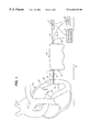
- the excising assembly 17 has a tapered dilator tip 21 optionally having a distal end of an optical fiber means 20 , preferably a bundle of fibers (see FIG. 1 ), which extends through the excising assembly 17 and the hand-held control device 16 .
- the optical fiber means 20 may be of any design and may include single fibers as well as the preferred bundle of fibers.
- the tapered dilator tip 21 optionally has a length of about 1 to 2 mm.
- the excising assembly 17 also has a measurement scale 41 on its surface to indicate its depth of penetration within tissue.
- the activated laser emitting a low-level energy laser beam through the distal end of the optical fiber means 20 provides a low energy ablation of tissue to ease the advancement of the dilator tip and excising assembly to pierce through the epicardium and tunnel through the myocardium.
- the laser is activated by depression of a foot switch which is connected to the power generator responsible for powering the laser source 22 .
- the optical fiber means 20 which, at its distal end, as shown in FIG. 2, has a diameter of around 0.08-0.2 mm.
- the optical fiber means may be either a single fiber or comprised of a plurality (e.g. FIGS. 3A to 3 C) of smaller glass fibers.
- the optical fiber means is optionally surrounded by a suitable plastic material 34 , such as 353 ND Epoxy, which protects the glass fiber and is particularly useful in holding together multiple glass fibers.
- the bundle Near its distal tip, the bundle preferably is surrounded by an annular tantalum marker 36 which serves to retain the bundle closely packed in a proper geometric boundary.
- the layer surrounding the annular tantalum marker 36 and/or the plastic material 34 comprises a substance-filled cylindrical shell insertion means 35 , preferably made of plastic such as polypropylene, having a wall thickness of 0.008 mm and equidistantly surrounding the optical fiber means 20 at a distance suitable to allow for delivery of drugs in the space ( 37 ) between the optical fiber means 20 and the shell 35 .
- the optical fiber means 20 described is for purposes of illustration only and it will be recogized by those skilled in the art that single fibers and other laser delivery systems may be used.
- the optical fiber means 20 and the substance-filled cylindrical shell insertion means 35 as described above run together as the combined optical fiber/insertion cable 45 .
- An optional source of the substance is a syringe 72 located in a pump controller 71 as seen in FIGS. 7 and 8.
- the syringe 72 fits within a syringe hold 70 within the pump controller 71 .
- the plunger 81 of the syringe 72 could optionally have a screw 80 at its distal end which is turned moving the plunger 81 forward into the syringe 72 by a step motor 77 within the pump controller 71 .
- a black box 78 is connected to and powers the step motor 77 to rotate in direction A (as seen in FIG. 8) which causes the screw 80 to move in direction B.
- the substance 85 within the syringe 72 is dispensed into a tubing 82 which ends in a T shaped junction 79 .
- the combined optical fiber/insertion cable 45 runs within the top of the T shaped junction 79 of the tubing 82 .
- the ends of the T shaped junction 79 are sealed around the combined optical fiber/insertion cable 45 by some sealing means, for example, glue at position 86 .
- Inlet ports 84 of the cylindrical shell insertion means 35 of the combined optical fiber/insertion cable 45 allow for the inflow of the substance 85 from the tubing 82 within the T junction 79 .
- the cylindrical shell insertion means 35 is sealed at a point 87 that is proximal to the inlet ports 84 .
- the substance 85 therefore, moves in a distal direction within the cylindrical shell insertion means 35 towards the excising assembly 17 .
- a sleeve 83 covers the T junction 79 to further support the integrity of the connection between the tubing 82 and the cylindrical shell insertion means 35 of the combined optical fiber/insertion cable 45 .
- the pump controller 71 has a drug delivery selection setting 74 on its surface to activate the pumping of the substance 85 .
- the drug delivery selection setting 74 could optionally provide settings for off (1), pump while lasing only (2), pump while punching pockets only (3) and pump while lasing and punching pockets (4).
- a speed setting 73 for the step motor 77 is also located on the surface of the pump controller 71 .
- the speed setting 73 allows for 1) the stepping motors rate to be determined in cases of continuous flow of the substance, for example the step motor 77 turns at x steps per second, and 2) the number of steps to create a certain size drop of the substance 85 , for example, large drops (5-20 steps) and small drops (1-3 steps).
- An incoming electrical wire 75 carries signal input to the black box indicating the timing of the laser and the punch of the excising assembly 17 .
- An outgoing electrical wire 76 connects to a power source for powering the pump controller 71 .
- the excising assembly 17 comprises two semi-dividable shell portions (distal 21 and proximal 48 ) unified by a common central rigid hollow cylinder 46 running the full length of the longitudinal axis of the excising assembly 17 .
- the common central rigid hollow cylinder 46 extends beyond the span of the two shell portions ( 21 and 48 ) and ends proximally with the proximal end of a solenoid connector flange 53 .
- the solenoid connector flange 53 comprises a relatively short cylindrical shell surrounding the common central rigid hollow cylinder 46 at the proximal end of the excising assembly 17 .
- the common central rigid hollow cylinder 46 carries the combined optical fiber/insertion cable 45 within it from the distal through the proximal end of the excising assembly 17 .
- the outer shell unit 49 comprises a rigid hollow cylinder of stainless steel having a diameter range of 0.5 to 2.0 mm having an open distal end with sharp edges and an open proximal end.
- a control device flange 50 comprising a rigid cylindrical shell is attached to the proximal end of the outer shell unit 49 .
- the control device flange 50 connects in a removable manner the excising assembly 17 to the hand-held control device 16 .
- the distal and proximal ends of the control device flange 50 preferably comprise closed surfaces to the point of their attachment with the outer shell unit 49 and the proximal end of the outer shell unit 49 , respectively.
- a cylindrical plunger 51 the inner cylindrical shell unit, has an outer cylindrical surface lying flush against the inner surface of the outer shell unit 49 and an inner cylindrical surface lying flush against the outer surface of the common central rigid hollow cylinder 46 . Each surface of the cylindrical plunger 51 slides easily along the other surface it opposes.
- the distal and proximal ends of the cylindrical plunger 51 comprise closed surfaces.
- the distal end of the cylindrical plunger 51 preferably lies in its relaxed position somewhat proximally to the distal end of the outer shell unit 49 .
- the proximal end of the cylindrical plunger 51 preferably protrudes in its relaxed position beyond the proximal end of the control device flange 50 .
- the cylindrical plunger 51 Near its proximal end, the cylindrical plunger 51 has a slotted groove indentation 52 on its outer cylindrical surface.
- a black box 65 within the hand-held control device 16 preferably is connected to a synchronized timing means for sensing contractions and expansions of the beating heart.
- the synchronized timing means comprises a pressure transducer 63 , for example a thin film piezo electric pressure transducer, which optionally is located on the outer surface of the outer shell unit 49 , and preferably the distal section of the outer shell unit 49 , and electric wiring 64 connected to the pressure transducer distally.
- the electric wiring 64 runs proximally within the common central rigid hollow cylinder 46 into the hand-held control device 16 and to the black box 65 .
- the sychronized timing means may be an EKG with signal input to the black box 65 .
- the open/close action of the punch would occur sometime during systole, and preferably at a threshold of contractile pressure as discussed above.
- the punch button switch 66 must also be enabled from an operator's depression of a push button 42 on the surface of the hand-held control device 16 .
- the powered forward solenoid 62 propels a solenoid/flange connector 67 distally for approximately 1-3 mm within the hand-held control device 16 and then (or optionally with the solenoids reversal) pulls it back proximally in a rapid movement.
- the distal movement of the solenoid/flange connector 67 is optionally synchronized to occur at the point of beginning systole or at a minimum threshold of pressure and the proximal movement at the point of maximum contraction of systole.
- the solenoid/flange connector 67 has a slotted groove on its surface for holding part of the solenoid connector flange 53 of the excising assembly 17 .
- the distal movement of the solenoid/flange connector 67 therefore also distally propels the common central rigid hollow cylinder 46 and its attached dilator tip portion 21 , thereby opening a gap between the two semi-dividable portions ( 21 and 48 ) of the excising assembly 17 the same distance allowing myocardial tissue to enter the gap.
- the dilator tip portion 21 is rapidly pulled back to close upon the reservoir/plunger portion 48 thereby operating the punching mechanism to excise myocardial tissue and trap the tissue within the reservoir means 44 .
- an excised tissue ejection indicator 60 on the hand-held control device 16 has a cross piece 61 that aligns with the inferior aspect of the slotted groove indentation 52 .
- the cross piece 61 thereby showing on the excised tissue selection indicator 60 , the amount of excised tissue trapped within the reservoir means 44 . Removal of the excising assembly 17 from the hand-held control device unit, allows for greater ease in forcing the cylindrical plunger 51 distally through the reservoir means 44 to release the trapped excised tissue.
- a substance is released through the portal of the cylindrical shell insertion means 35 at the distal end of the dilator tip portion 21 of the excising assembly 17 on a continuous-flow and/or bolus flow basis where the bolus of more preferably a pharmacologically active substance, for example VEGF, is released into the newly created pocket.
- a drug-filled pocket is thereby produced.
- the surgeon first passes the excising assembly 17 through the epicardium 12 , myocardium 13 and endocardium 15 to enter the ventricle 14 whereupon the reduction in resistance met with further advancement of the excising assembly indicates to the surgeon the depth of the endocardium and the thickness of the heart wall relative to the measurement scale 41 on the surface of the excising assembly 17 .
- the surgeon may alternatively withdraw the excising assembly 17 through the passage created firing the punch button 42 at designated distances within the wall of the myocardium 13 as measured on the measurement scale 41 during the withdrawal. The surgeon thereby creates drug filled pockets at designated depths within the myocardium.
- the surgeon Upon full retraction of the excising assembly 17 from the ventricle wall, the surgeon will continue with subsequent entries into the myocardium until the punch (the two semi-dividable portions of the excising assembly 17 ) dulls or the excised tissue ejection indicator 60 indicate the reservoir means 44 is full. At that point a change of excising assembly 17 for cleanout or sharpness will be done.
- FIGS. 6A through 6C demonstrate how the excising assembly 16 is connected in a removable manner to the hand-held control device ( 16 ).
- the combined optical/insertion cable 45 is threaded from the hand-held control device ( 16 ) into the proximal end of the common central rigid hollow cylinder 46 of the excising assembly 17 .
- the electrical wire 64 for the pressure transducer 63 runs along the outer surface of the outer shell unit 49 to connect to 360 degree contact strips on the surface of the control device flange 50 , which upon contact with the housing in the hand-held control device 16 , conducts signals to the black box 65 within the hand-held control device.
Abstract
Description
Claims (19)
Priority Applications (1)
| Application Number | Priority Date | Filing Date | Title |
|---|---|---|---|
| US09/444,772 US6482220B1 (en) | 1996-12-26 | 1999-11-22 | Method and apparatus for creation of drug delivery and/or stimulation pockets in myocardium |
Applications Claiming Priority (2)
| Application Number | Priority Date | Filing Date | Title |
|---|---|---|---|
| US08/773,778 US6067988A (en) | 1996-12-26 | 1996-12-26 | Method for creation of drug delivery and/or stimulation pockets in myocardium |
| US09/444,772 US6482220B1 (en) | 1996-12-26 | 1999-11-22 | Method and apparatus for creation of drug delivery and/or stimulation pockets in myocardium |
Related Parent Applications (1)
| Application Number | Title | Priority Date | Filing Date |
|---|---|---|---|
| US08/773,778 Division US6067988A (en) | 1996-12-26 | 1996-12-26 | Method for creation of drug delivery and/or stimulation pockets in myocardium |
Publications (1)
| Publication Number | Publication Date |
|---|---|
| US6482220B1 true US6482220B1 (en) | 2002-11-19 |
Family
ID=25099284
Family Applications (2)
| Application Number | Title | Priority Date | Filing Date |
|---|---|---|---|
| US08/773,778 Expired - Lifetime US6067988A (en) | 1996-12-26 | 1996-12-26 | Method for creation of drug delivery and/or stimulation pockets in myocardium |
| US09/444,772 Expired - Fee Related US6482220B1 (en) | 1996-12-26 | 1999-11-22 | Method and apparatus for creation of drug delivery and/or stimulation pockets in myocardium |
Family Applications Before (1)
| Application Number | Title | Priority Date | Filing Date |
|---|---|---|---|
| US08/773,778 Expired - Lifetime US6067988A (en) | 1996-12-26 | 1996-12-26 | Method for creation of drug delivery and/or stimulation pockets in myocardium |
Country Status (1)
| Country | Link |
|---|---|
| US (2) | US6067988A (en) |
Cited By (32)
| Publication number | Priority date | Publication date | Assignee | Title |
|---|---|---|---|---|
| US20030137008A1 (en) * | 2000-03-28 | 2003-07-24 | Hidetoshi Nozaki | Solid state imaging device having a photodiode and a MOSFET and method of manufacturing the same |
| US20040133969A1 (en) * | 2003-01-10 | 2004-07-15 | Tyler Pipe Company, A Division Of Ransom Industries, Lp | Closet carrier system and method of assembly |
| US20080058850A1 (en) * | 2005-02-14 | 2008-03-06 | Ernest Feiler | Method and apparatus for providing immediate supplemental blood flow to an organ |
| US20100004669A1 (en) * | 2007-12-03 | 2010-01-07 | Smith Kevin W | Cordless Hand-Held Ultrasonic Cautery Cutting Device and Method |
| US7704222B2 (en) | 1998-09-10 | 2010-04-27 | Jenavalve Technology, Inc. | Methods and conduits for flowing blood from a heart chamber to a blood vessel |
| US8061014B2 (en) | 2007-12-03 | 2011-11-22 | Covidien Ag | Method of assembling a cordless hand-held ultrasonic cautery cutting device |
| US8372099B2 (en) | 2007-12-03 | 2013-02-12 | Covidien Ag | Cordless hand-held ultrasonic cautery cutting device |
| US8487199B2 (en) | 2008-11-06 | 2013-07-16 | Covidien Ag | Method of switching a surgical device |
| US8663262B2 (en) | 2007-12-03 | 2014-03-04 | Covidien Ag | Battery assembly for battery-powered surgical instruments |
| US9017355B2 (en) | 2007-12-03 | 2015-04-28 | Covidien Ag | Battery-powered hand-held ultrasonic surgical cautery cutting device |
| US9107690B2 (en) | 2007-12-03 | 2015-08-18 | Covidien Ag | Battery-powered hand-held ultrasonic surgical cautery cutting device |
| US9314261B2 (en) | 2007-12-03 | 2016-04-19 | Covidien Ag | Battery-powered hand-held ultrasonic surgical cautery cutting device |
| US10368898B2 (en) | 2016-05-05 | 2019-08-06 | Covidien Lp | Ultrasonic surgical instrument |
| US10571435B2 (en) | 2017-06-08 | 2020-02-25 | Covidien Lp | Systems and methods for digital control of ultrasonic devices |
| US10582944B2 (en) | 2018-02-23 | 2020-03-10 | Covidien Lp | Ultrasonic surgical instrument with torque assist feature |
| US10993805B2 (en) | 2008-02-26 | 2021-05-04 | Jenavalve Technology, Inc. | Stent for the positioning and anchoring of a valvular prosthesis in an implantation site in the heart of a patient |
| US11065138B2 (en) | 2016-05-13 | 2021-07-20 | Jenavalve Technology, Inc. | Heart valve prosthesis delivery system and method for delivery of heart valve prosthesis with introducer sheath and loading system |
| US11185405B2 (en) | 2013-08-30 | 2021-11-30 | Jenavalve Technology, Inc. | Radially collapsible frame for a prosthetic valve and method for manufacturing such a frame |
| US11197754B2 (en) | 2017-01-27 | 2021-12-14 | Jenavalve Technology, Inc. | Heart valve mimicry |
| US11229449B2 (en) | 2018-02-05 | 2022-01-25 | Covidien Lp | Ultrasonic horn, ultrasonic transducer assembly, and ultrasonic surgical instrument including the same |
| US11246621B2 (en) | 2018-01-29 | 2022-02-15 | Covidien Lp | Ultrasonic transducers and ultrasonic surgical instruments including the same |
| US11246617B2 (en) | 2018-01-29 | 2022-02-15 | Covidien Lp | Compact ultrasonic transducer and ultrasonic surgical instrument including the same |
| US11259832B2 (en) | 2018-01-29 | 2022-03-01 | Covidien Lp | Ultrasonic horn for an ultrasonic surgical instrument, ultrasonic surgical instrument including the same, and method of manufacturing an ultrasonic horn |
| US11337800B2 (en) | 2015-05-01 | 2022-05-24 | Jenavalve Technology, Inc. | Device and method with reduced pacemaker rate in heart valve replacement |
| US11357624B2 (en) | 2007-04-13 | 2022-06-14 | Jenavalve Technology, Inc. | Medical device for treating a heart valve insufficiency |
| US11478268B2 (en) | 2019-08-16 | 2022-10-25 | Covidien Lp | Jaw members for surgical instruments and surgical instruments incorporating the same |
| US11517431B2 (en) | 2005-01-20 | 2022-12-06 | Jenavalve Technology, Inc. | Catheter system for implantation of prosthetic heart valves |
| US11564794B2 (en) | 2008-02-26 | 2023-01-31 | Jenavalve Technology, Inc. | Stent for the positioning and anchoring of a valvular prosthesis in an implantation site in the heart of a patient |
| US11589981B2 (en) | 2010-05-25 | 2023-02-28 | Jenavalve Technology, Inc. | Prosthetic heart valve and transcatheter delivered endoprosthesis comprising a prosthetic heart valve and a stent |
| US11617599B2 (en) | 2020-10-15 | 2023-04-04 | Covidien Lp | Ultrasonic surgical instrument |
| US11666357B2 (en) | 2019-09-16 | 2023-06-06 | Covidien Lp | Enclosure for electronics of a surgical instrument |
| US11717312B2 (en) | 2021-10-01 | 2023-08-08 | Covidien Lp | Surgical system including blade visualization markings |
Families Citing this family (19)
| Publication number | Priority date | Publication date | Assignee | Title |
|---|---|---|---|---|
| US5755682A (en) | 1996-08-13 | 1998-05-26 | Heartstent Corporation | Method and apparatus for performing coronary artery bypass surgery |
| US6086582A (en) * | 1997-03-13 | 2000-07-11 | Altman; Peter A. | Cardiac drug delivery system |
| US6406488B1 (en) * | 1998-08-27 | 2002-06-18 | Heartstent Corporation | Healing transmyocardial implant |
| US6641610B2 (en) * | 1998-09-10 | 2003-11-04 | Percardia, Inc. | Valve designs for left ventricular conduits |
| US6290728B1 (en) | 1998-09-10 | 2001-09-18 | Percardia, Inc. | Designs for left ventricular conduit |
| US6409697B2 (en) | 1999-05-04 | 2002-06-25 | Heartstent Corporation | Transmyocardial implant with forward flow bias |
| US6638237B1 (en) | 1999-08-04 | 2003-10-28 | Percardia, Inc. | Left ventricular conduits and methods for delivery |
| US6253768B1 (en) | 1999-08-04 | 2001-07-03 | Percardia, Inc. | Vascular graft bypass |
| US6605053B1 (en) | 1999-09-10 | 2003-08-12 | Percardia, Inc. | Conduit designs and related methods for optimal flow control |
| US20020032478A1 (en) * | 2000-08-07 | 2002-03-14 | Percardia, Inc. | Myocardial stents and related methods of providing direct blood flow from a heart chamber to a coronary vessel |
| US6976990B2 (en) | 2001-01-25 | 2005-12-20 | Percardia, Inc. | Intravascular ventriculocoronary bypass via a septal passageway |
| US7776025B2 (en) * | 2001-10-29 | 2010-08-17 | Edwards Lifesciences Corporation | Method for providing medicament to tissue |
| US6949118B2 (en) * | 2002-01-16 | 2005-09-27 | Percardia, Inc. | Encased implant and methods |
| US7008397B2 (en) | 2002-02-13 | 2006-03-07 | Percardia, Inc. | Cardiac implant and methods |
| US7326219B2 (en) * | 2002-09-09 | 2008-02-05 | Wilk Patent Development | Device for placing transmyocardial implant |
| US20040147868A1 (en) * | 2003-01-27 | 2004-07-29 | Earl Bardsley | Myocardial implant with collar |
| JP4903689B2 (en) * | 2004-04-08 | 2012-03-28 | サンガモ バイオサイエンシズ インコーポレイテッド | Methods and compositions for treating neuropathy and neurodegenerative symptoms |
| CA2561565C (en) * | 2004-04-08 | 2013-11-26 | Sangamo Biosciences, Inc. | Methods for repression of phospholamban gene and modulating cardiac contractility |
| US7787950B1 (en) * | 2006-11-03 | 2010-08-31 | Pacesetter, Inc. | Techniques for delivery of stem cell and related therapies to treat cardiac conditions |
Citations (10)
| Publication number | Priority date | Publication date | Assignee | Title |
|---|---|---|---|---|
| US5125926A (en) * | 1990-09-24 | 1992-06-30 | Laser Engineering, Inc. | Heart-synchronized pulsed laser system |
| US5133360A (en) * | 1991-03-07 | 1992-07-28 | Spears Colin P | Spears retriever |
| EP0515867A2 (en) | 1991-05-01 | 1992-12-02 | The Trustees Of Columbia University In The City Of New York | Myocardial revascularization through the endocardial surface using a laser |
| US5498238A (en) | 1990-06-15 | 1996-03-12 | Cortrak Medical, Inc. | Simultaneous angioplasty and phoretic drug delivery |
| WO1996035469A1 (en) | 1995-05-10 | 1996-11-14 | Cardiogenesis Corporation | System for treating or diagnosing heart tissue |
| WO1997047253A1 (en) | 1996-06-14 | 1997-12-18 | Kriton Medical, Inc. | Methods and devices for reducing angina, enhancing myocardial perfusion and increasing cardiac function |
| WO1998005307A1 (en) | 1996-08-08 | 1998-02-12 | Localmed, Inc. | Transmural drug delivery method and apparatus |
| US5840059A (en) * | 1995-06-07 | 1998-11-24 | Cardiogenesis Corporation | Therapeutic and diagnostic agent delivery |
| US5840075A (en) * | 1996-08-23 | 1998-11-24 | Eclipse Surgical Technologies, Inc. | Dual laser device for transmyocardial revascularization procedures |
| US5925012A (en) * | 1996-12-27 | 1999-07-20 | Eclipse Surgical Technologies, Inc. | Laser assisted drug delivery |
Family Cites Families (1)
| Publication number | Priority date | Publication date | Assignee | Title |
|---|---|---|---|---|
| US4846171A (en) * | 1986-10-06 | 1989-07-11 | Gv Medical, Inc. | Laser catheter adjustable control apparatus |
-
1996
- 1996-12-26 US US08/773,778 patent/US6067988A/en not_active Expired - Lifetime
-
1999
- 1999-11-22 US US09/444,772 patent/US6482220B1/en not_active Expired - Fee Related
Patent Citations (10)
| Publication number | Priority date | Publication date | Assignee | Title |
|---|---|---|---|---|
| US5498238A (en) | 1990-06-15 | 1996-03-12 | Cortrak Medical, Inc. | Simultaneous angioplasty and phoretic drug delivery |
| US5125926A (en) * | 1990-09-24 | 1992-06-30 | Laser Engineering, Inc. | Heart-synchronized pulsed laser system |
| US5133360A (en) * | 1991-03-07 | 1992-07-28 | Spears Colin P | Spears retriever |
| EP0515867A2 (en) | 1991-05-01 | 1992-12-02 | The Trustees Of Columbia University In The City Of New York | Myocardial revascularization through the endocardial surface using a laser |
| WO1996035469A1 (en) | 1995-05-10 | 1996-11-14 | Cardiogenesis Corporation | System for treating or diagnosing heart tissue |
| US5840059A (en) * | 1995-06-07 | 1998-11-24 | Cardiogenesis Corporation | Therapeutic and diagnostic agent delivery |
| WO1997047253A1 (en) | 1996-06-14 | 1997-12-18 | Kriton Medical, Inc. | Methods and devices for reducing angina, enhancing myocardial perfusion and increasing cardiac function |
| WO1998005307A1 (en) | 1996-08-08 | 1998-02-12 | Localmed, Inc. | Transmural drug delivery method and apparatus |
| US5840075A (en) * | 1996-08-23 | 1998-11-24 | Eclipse Surgical Technologies, Inc. | Dual laser device for transmyocardial revascularization procedures |
| US5925012A (en) * | 1996-12-27 | 1999-07-20 | Eclipse Surgical Technologies, Inc. | Laser assisted drug delivery |
Cited By (68)
| Publication number | Priority date | Publication date | Assignee | Title |
|---|---|---|---|---|
| US7704222B2 (en) | 1998-09-10 | 2010-04-27 | Jenavalve Technology, Inc. | Methods and conduits for flowing blood from a heart chamber to a blood vessel |
| US7736327B2 (en) | 1998-09-10 | 2010-06-15 | Jenavalve Technology, Inc. | Methods and conduits for flowing blood from a heart chamber to a blood vessel |
| US8216174B2 (en) | 1998-09-10 | 2012-07-10 | Jenavalve Technology, Inc. | Methods and conduits for flowing blood from a heart chamber to a blood vessel |
| US8597226B2 (en) | 1998-09-10 | 2013-12-03 | Jenavalve Technology, Inc. | Methods and conduits for flowing blood from a heart chamber to a blood vessel |
| US20030137008A1 (en) * | 2000-03-28 | 2003-07-24 | Hidetoshi Nozaki | Solid state imaging device having a photodiode and a MOSFET and method of manufacturing the same |
| US20040133969A1 (en) * | 2003-01-10 | 2004-07-15 | Tyler Pipe Company, A Division Of Ransom Industries, Lp | Closet carrier system and method of assembly |
| US11517431B2 (en) | 2005-01-20 | 2022-12-06 | Jenavalve Technology, Inc. | Catheter system for implantation of prosthetic heart valves |
| US20080058850A1 (en) * | 2005-02-14 | 2008-03-06 | Ernest Feiler | Method and apparatus for providing immediate supplemental blood flow to an organ |
| US8088109B2 (en) * | 2005-02-14 | 2012-01-03 | Surgical Pioneering, LLC | Method and apparatus for providing immediate supplemental blood flow to an organ |
| US11357624B2 (en) | 2007-04-13 | 2022-06-14 | Jenavalve Technology, Inc. | Medical device for treating a heart valve insufficiency |
| US9017355B2 (en) | 2007-12-03 | 2015-04-28 | Covidien Ag | Battery-powered hand-held ultrasonic surgical cautery cutting device |
| US9861382B2 (en) | 2007-12-03 | 2018-01-09 | Covidien Ag | Cordless hand-held ultrasonic cautery cutting device |
| US8333778B2 (en) | 2007-12-03 | 2012-12-18 | Covidien Ag | Cordless hand-held ultrasonic cautery cutting device |
| US8333779B2 (en) | 2007-12-03 | 2012-12-18 | Covidien Ag | Method of maintaining constant movement of a cutting blade of an ultrasonic waveguide |
| US8372099B2 (en) | 2007-12-03 | 2013-02-12 | Covidien Ag | Cordless hand-held ultrasonic cautery cutting device |
| US8372101B2 (en) | 2007-12-03 | 2013-02-12 | Covidien Ag | Cordless hand-held ultrasonic cautery cutting device |
| US8377085B2 (en) | 2007-12-03 | 2013-02-19 | Covidien Ag | Cordless hand-held ultrasonic cautery cutting device |
| US8403950B2 (en) | 2007-12-03 | 2013-03-26 | Covidien Ag | Cordless hand-held ultrasonic cautery cutting device |
| US8403948B2 (en) | 2007-12-03 | 2013-03-26 | Covidien Ag | Cordless hand-held ultrasonic cautery cutting device |
| US8403949B2 (en) * | 2007-12-03 | 2013-03-26 | Covidien Ag | Cordless hand-held ultrasonic cautery cutting device |
| US8419757B2 (en) | 2007-12-03 | 2013-04-16 | Covidien Ag | Cordless hand-held ultrasonic cautery cutting device |
| US8418349B2 (en) | 2007-12-03 | 2013-04-16 | Covidien Ag | Method of assembling a cordless hand-held ultrasonic cautery cutting device |
| US8419758B2 (en) | 2007-12-03 | 2013-04-16 | Covidien Ag | Cordless hand-held ultrasonic cautery cutting device |
| US8425545B2 (en) | 2007-12-03 | 2013-04-23 | Covidien Ag | Cordless hand-held ultrasonic cautery cutting device and method |
| US8435257B2 (en) | 2007-12-03 | 2013-05-07 | Covidien Ag | Cordless hand-held ultrasonic cautery cutting device and method |
| US8439939B2 (en) | 2007-12-03 | 2013-05-14 | Covidien Ag | Method of powering a surgical instrument |
| US8444662B2 (en) | 2007-12-03 | 2013-05-21 | Covidien Lp | Cordless hand-held ultrasonic cautery cutting device |
| US20100004669A1 (en) * | 2007-12-03 | 2010-01-07 | Smith Kevin W | Cordless Hand-Held Ultrasonic Cautery Cutting Device and Method |
| US11478820B2 (en) | 2007-12-03 | 2022-10-25 | Covidien Ag | Battery-powered hand-held ultrasonic surgical cautery cutting device |
| US8061014B2 (en) | 2007-12-03 | 2011-11-22 | Covidien Ag | Method of assembling a cordless hand-held ultrasonic cautery cutting device |
| US8663262B2 (en) | 2007-12-03 | 2014-03-04 | Covidien Ag | Battery assembly for battery-powered surgical instruments |
| US10799913B2 (en) | 2007-12-03 | 2020-10-13 | Covidien Lp | Battery-powered hand-held ultrasonic surgical cautery cutting device |
| US10456158B2 (en) | 2007-12-03 | 2019-10-29 | Covidien Ag | Cordless hand-held ultrasonic surgical device |
| US8992555B2 (en) | 2007-12-03 | 2015-03-31 | Covidien Ag | Method of assembling a cordless hand-held ultrasonic cautery cutting device |
| US8197502B2 (en) | 2007-12-03 | 2012-06-12 | Covidien Ag | Method of maintaining constant movement of a cutting blade on an ultrasonic waveguide |
| US9084625B2 (en) | 2007-12-03 | 2015-07-21 | Covidien Ag | Battery assembly for battery-powered surgical instruments |
| US9107690B2 (en) | 2007-12-03 | 2015-08-18 | Covidien Ag | Battery-powered hand-held ultrasonic surgical cautery cutting device |
| US9314261B2 (en) | 2007-12-03 | 2016-04-19 | Covidien Ag | Battery-powered hand-held ultrasonic surgical cautery cutting device |
| US9782180B2 (en) | 2007-12-03 | 2017-10-10 | Covidien Ag | Method of maintaining constant movement of a cutting blade of an ultrasonic waveguide |
| US8236020B2 (en) | 2007-12-03 | 2012-08-07 | Covidien Ag | Cordless hand-held ultrasonic cautery cutting device |
| US9872696B2 (en) | 2007-12-03 | 2018-01-23 | Covidien Ag | Battery-powered hand-held ultrasonic surgical cautery cutting device |
| US10426508B2 (en) | 2007-12-03 | 2019-10-01 | Covidien Ag | Cordless hand-held ultrasonic cautery device |
| US11564794B2 (en) | 2008-02-26 | 2023-01-31 | Jenavalve Technology, Inc. | Stent for the positioning and anchoring of a valvular prosthesis in an implantation site in the heart of a patient |
| US11154398B2 (en) | 2008-02-26 | 2021-10-26 | JenaValve Technology. Inc. | Stent for the positioning and anchoring of a valvular prosthesis in an implantation site in the heart of a patient |
| US10993805B2 (en) | 2008-02-26 | 2021-05-04 | Jenavalve Technology, Inc. | Stent for the positioning and anchoring of a valvular prosthesis in an implantation site in the heart of a patient |
| US8487199B2 (en) | 2008-11-06 | 2013-07-16 | Covidien Ag | Method of switching a surgical device |
| US8502091B2 (en) | 2008-11-06 | 2013-08-06 | Covidien Ag | Two-Stage Switch for Surgical Device |
| US8742269B2 (en) | 2008-11-06 | 2014-06-03 | Covidien Ag | Two-stage switch for surgical device |
| US8497436B2 (en) | 2008-11-06 | 2013-07-30 | Covidien Ag | Two-stage switch for surgical device |
| US8497437B2 (en) | 2008-11-06 | 2013-07-30 | Covidien Ag | Method of switching a surgical device |
| US11589981B2 (en) | 2010-05-25 | 2023-02-28 | Jenavalve Technology, Inc. | Prosthetic heart valve and transcatheter delivered endoprosthesis comprising a prosthetic heart valve and a stent |
| US11185405B2 (en) | 2013-08-30 | 2021-11-30 | Jenavalve Technology, Inc. | Radially collapsible frame for a prosthetic valve and method for manufacturing such a frame |
| US11337800B2 (en) | 2015-05-01 | 2022-05-24 | Jenavalve Technology, Inc. | Device and method with reduced pacemaker rate in heart valve replacement |
| US10368898B2 (en) | 2016-05-05 | 2019-08-06 | Covidien Lp | Ultrasonic surgical instrument |
| US11266432B2 (en) | 2016-05-05 | 2022-03-08 | Covidien Lp | Ultrasonic surgical instrument |
| US11065138B2 (en) | 2016-05-13 | 2021-07-20 | Jenavalve Technology, Inc. | Heart valve prosthesis delivery system and method for delivery of heart valve prosthesis with introducer sheath and loading system |
| US11197754B2 (en) | 2017-01-27 | 2021-12-14 | Jenavalve Technology, Inc. | Heart valve mimicry |
| US10571435B2 (en) | 2017-06-08 | 2020-02-25 | Covidien Lp | Systems and methods for digital control of ultrasonic devices |
| US11259832B2 (en) | 2018-01-29 | 2022-03-01 | Covidien Lp | Ultrasonic horn for an ultrasonic surgical instrument, ultrasonic surgical instrument including the same, and method of manufacturing an ultrasonic horn |
| US11246617B2 (en) | 2018-01-29 | 2022-02-15 | Covidien Lp | Compact ultrasonic transducer and ultrasonic surgical instrument including the same |
| US11246621B2 (en) | 2018-01-29 | 2022-02-15 | Covidien Lp | Ultrasonic transducers and ultrasonic surgical instruments including the same |
| US11229449B2 (en) | 2018-02-05 | 2022-01-25 | Covidien Lp | Ultrasonic horn, ultrasonic transducer assembly, and ultrasonic surgical instrument including the same |
| US11304721B2 (en) | 2018-02-23 | 2022-04-19 | Covidien Lp | Ultrasonic surgical instrument with torque assist feature |
| US10582944B2 (en) | 2018-02-23 | 2020-03-10 | Covidien Lp | Ultrasonic surgical instrument with torque assist feature |
| US11478268B2 (en) | 2019-08-16 | 2022-10-25 | Covidien Lp | Jaw members for surgical instruments and surgical instruments incorporating the same |
| US11666357B2 (en) | 2019-09-16 | 2023-06-06 | Covidien Lp | Enclosure for electronics of a surgical instrument |
| US11617599B2 (en) | 2020-10-15 | 2023-04-04 | Covidien Lp | Ultrasonic surgical instrument |
| US11717312B2 (en) | 2021-10-01 | 2023-08-08 | Covidien Lp | Surgical system including blade visualization markings |
Also Published As
| Publication number | Publication date |
|---|---|
| US6067988A (en) | 2000-05-30 |
Similar Documents
| Publication | Publication Date | Title |
|---|---|---|
| US6482220B1 (en) | Method and apparatus for creation of drug delivery and/or stimulation pockets in myocardium | |
| US6231568B1 (en) | Channel-forming laser energy device | |
| US6120520A (en) | Apparatus and methods for stimulating revascularization and/or tissue growth | |
| AU730720B2 (en) | Transvascular TMR device and method | |
| EP0792624B1 (en) | Surgical apparatus for transmyocardial revascularization | |
| US5703985A (en) | Optical fiber device and method for laser surgery procedures | |
| US5380316A (en) | Method for intra-operative myocardial device revascularization | |
| EP0801928B1 (en) | Laser device with piercing tip for transmyocardial revascularization procedures | |
| US5782823A (en) | Laser device for transmyocardial revascularization procedures including means for enabling a formation of a pilot hole in the epicardium | |
| US5389096A (en) | System and method for percutaneous myocardial revascularization | |
| EP0934728A2 (en) | Selective treatment of endocardial/myocardial boundary | |
| US6011889A (en) | Piercing point optical fiber device for laser surgery procedures | |
| EP0973455A1 (en) | Radio frequency transmyocardial revascularization corer | |
| WO1999017671A1 (en) | Transmyocardial revascularization using radiofrequency energy | |
| CA2304188A1 (en) | Devices and methods for performing transmyocardial revascularization | |
| US6283955B1 (en) | Laser ablation device | |
| AU8506398A (en) | Apparatus and method for transmyocardial revascularization by laser ablation | |
| AU5194701A (en) | Transvascular TMR device and method | |
| AU9409698A (en) | Selective treatment of endocardial/myocardial boundary |
Legal Events
| Date | Code | Title | Description |
|---|---|---|---|
| FPAY | Fee payment |
Year of fee payment: 4 |
|
| FPAY | Fee payment |
Year of fee payment: 8 |
|
| AS | Assignment |
Owner name: GENERAL ELECTRIC CAPITAL CORPORATION, AS AGENT, MA Free format text: SECURITY AGREEMENT;ASSIGNOR:CARDIOGENESIS CORPORATION;REEL/FRAME:026540/0064 Effective date: 20110630 |
|
| REMI | Maintenance fee reminder mailed | ||
| LAPS | Lapse for failure to pay maintenance fees | ||
| STCH | Information on status: patent discontinuation |
Free format text: PATENT EXPIRED DUE TO NONPAYMENT OF MAINTENANCE FEES UNDER 37 CFR 1.362 |
|
| FP | Expired due to failure to pay maintenance fee |
Effective date: 20141119 |
|
| AS | Assignment |
Owner name: HEALTHCARE FINANCIAL SOLUTIONS, LLC, AS SUCCESSOR AGENT, MARYLAND Free format text: ASSIGNMENT OF INTELLECTUAL PROPERTY SECURITY AGREEMENT;ASSIGNOR:GENERAL ELECTRIC CAPITAL CORPORATION, AS RETIRING AGENT;REEL/FRAME:037146/0466 Effective date: 20151118 Owner name: HEALTHCARE FINANCIAL SOLUTIONS, LLC, AS SUCCESSOR Free format text: ASSIGNMENT OF INTELLECTUAL PROPERTY SECURITY AGREEMENT;ASSIGNOR:GENERAL ELECTRIC CAPITAL CORPORATION, AS RETIRING AGENT;REEL/FRAME:037146/0466 Effective date: 20151118 |
|
| AS | Assignment |
Owner name: ON-X LIFE TECHNOLOGIES, INC. (F/K/A MCRI, INC.), GEORGIA Free format text: RELEASE OF SECURITY INTEREST IN PATENTS;ASSIGNOR:HEALTHCARE FINANCIAL SOLUTIONS, LLC, AS ADMINISTRATIVE AGENT;REEL/FRAME:044621/0240 Effective date: 20171201 Owner name: CARDIOGENESIS CORPORATION (N/K/A CRYOLIFE, INC.), GEORGIA Free format text: RELEASE OF SECURITY INTEREST IN PATENTS;ASSIGNOR:HEALTHCARE FINANCIAL SOLUTIONS, LLC, AS ADMINISTRATIVE AGENT;REEL/FRAME:044621/0240 Effective date: 20171201 Owner name: CARDIOGENESIS CORPORATION (N/K/A CRYOLIFE, INC.), Free format text: RELEASE OF SECURITY INTEREST IN PATENTS;ASSIGNOR:HEALTHCARE FINANCIAL SOLUTIONS, LLC, AS ADMINISTRATIVE AGENT;REEL/FRAME:044621/0240 Effective date: 20171201 Owner name: ON-X LIFE TECHNOLOGIES, INC. (F/K/A MCRI, INC.), G Free format text: RELEASE OF SECURITY INTEREST IN PATENTS;ASSIGNOR:HEALTHCARE FINANCIAL SOLUTIONS, LLC, AS ADMINISTRATIVE AGENT;REEL/FRAME:044621/0240 Effective date: 20171201 Owner name: VALVE SPECIAL PURPOSE CO., LLC, GEORGIA Free format text: RELEASE OF SECURITY INTEREST IN PATENTS;ASSIGNOR:HEALTHCARE FINANCIAL SOLUTIONS, LLC, AS ADMINISTRATIVE AGENT;REEL/FRAME:044621/0240 Effective date: 20171201 Owner name: HEMOSPHERE, INC., GEORGIA Free format text: RELEASE OF SECURITY INTEREST IN PATENTS;ASSIGNOR:HEALTHCARE FINANCIAL SOLUTIONS, LLC, AS ADMINISTRATIVE AGENT;REEL/FRAME:044621/0240 Effective date: 20171201 Owner name: CRYOLIFE, INC., GEORGIA Free format text: RELEASE OF SECURITY INTEREST IN PATENTS;ASSIGNOR:HEALTHCARE FINANCIAL SOLUTIONS, LLC, AS ADMINISTRATIVE AGENT;REEL/FRAME:044621/0240 Effective date: 20171201 Owner name: CRYOLIFE ACQUISITION CORPORATION, GEORGIA Free format text: RELEASE OF SECURITY INTEREST IN PATENTS;ASSIGNOR:HEALTHCARE FINANCIAL SOLUTIONS, LLC, AS ADMINISTRATIVE AGENT;REEL/FRAME:044621/0240 Effective date: 20171201 |