US6481997B1 - Multi-part candle wick die plates - Google Patents

Multi-part candle wick die plates Download PDF

Info

Publication number
US6481997B1
US6481997B1 US09/584,043 US58404300A US6481997B1 US 6481997 B1 US6481997 B1 US 6481997B1 US 58404300 A US58404300 A US 58404300A US 6481997 B1 US6481997 B1 US 6481997B1
Authority
US
United States
Prior art keywords
die
candle wick
lower member
wick
die plate
Prior art date
Legal status (The legal status is an assumption and is not a legal conclusion. Google has not performed a legal analysis and makes no representation as to the accuracy of the status listed.)
Expired - Fee Related
Application number
US09/584,043
Inventor
Bruce M. Campbell
Hershell P. Sablowski
Current Assignee (The listed assignees may be inaccurate. Google has not performed a legal analysis and makes no representation or warranty as to the accuracy of the list.)
Edwin B Stimpson Co Inc
Original Assignee
Edwin B Stimpson Co Inc
Priority date (The priority date is an assumption and is not a legal conclusion. Google has not performed a legal analysis and makes no representation as to the accuracy of the date listed.)
Filing date
Publication date
Application filed by Edwin B Stimpson Co Inc filed Critical Edwin B Stimpson Co Inc
Priority to US09/584,043 priority Critical patent/US6481997B1/en
Assigned to WICKS UNLIMITED, INC. reassignment WICKS UNLIMITED, INC. ASSIGNMENT OF ASSIGNORS INTEREST (SEE DOCUMENT FOR DETAILS). Assignors: CAMPBELL, BRUCE M., SABLOWSKI, HERSHELL P.
Assigned to EDWIN B. STIMPSON COMPANY, INC. reassignment EDWIN B. STIMPSON COMPANY, INC. ASSIGNMENT OF ASSIGNORS INTEREST (SEE DOCUMENT FOR DETAILS). Assignors: WICKS UNLIMITED, INC.
Application granted granted Critical
Publication of US6481997B1 publication Critical patent/US6481997B1/en
Anticipated expiration legal-status Critical
Expired - Fee Related legal-status Critical Current

Links

Images

Classifications

    • CCHEMISTRY; METALLURGY
    • C11ANIMAL OR VEGETABLE OILS, FATS, FATTY SUBSTANCES OR WAXES; FATTY ACIDS THEREFROM; DETERGENTS; CANDLES
    • C11CFATTY ACIDS FROM FATS, OILS OR WAXES; CANDLES; FATS, OILS OR FATTY ACIDS BY CHEMICAL MODIFICATION OF FATS, OILS, OR FATTY ACIDS OBTAINED THEREFROM
    • C11C5/00Candles
    • C11C5/006Candles wicks, related accessories
    • BPERFORMING OPERATIONS; TRANSPORTING
    • B29WORKING OF PLASTICS; WORKING OF SUBSTANCES IN A PLASTIC STATE IN GENERAL
    • B29CSHAPING OR JOINING OF PLASTICS; SHAPING OF MATERIAL IN A PLASTIC STATE, NOT OTHERWISE PROVIDED FOR; AFTER-TREATMENT OF THE SHAPED PRODUCTS, e.g. REPAIRING
    • B29C43/00Compression moulding, i.e. applying external pressure to flow the moulding material; Apparatus therefor
    • B29C43/003Compression moulding, i.e. applying external pressure to flow the moulding material; Apparatus therefor characterised by the choice of material
    • BPERFORMING OPERATIONS; TRANSPORTING
    • B29WORKING OF PLASTICS; WORKING OF SUBSTANCES IN A PLASTIC STATE IN GENERAL
    • B29KINDEXING SCHEME ASSOCIATED WITH SUBCLASSES B29B, B29C OR B29D, RELATING TO MOULDING MATERIALS OR TO MATERIALS FOR MOULDS, REINFORCEMENTS, FILLERS OR PREFORMED PARTS, e.g. INSERTS
    • B29K2091/00Use of waxes as moulding material
    • YGENERAL TAGGING OF NEW TECHNOLOGICAL DEVELOPMENTS; GENERAL TAGGING OF CROSS-SECTIONAL TECHNOLOGIES SPANNING OVER SEVERAL SECTIONS OF THE IPC; TECHNICAL SUBJECTS COVERED BY FORMER USPC CROSS-REFERENCE ART COLLECTIONS [XRACs] AND DIGESTS
    • Y10TECHNICAL SUBJECTS COVERED BY FORMER USPC
    • Y10STECHNICAL SUBJECTS COVERED BY FORMER USPC CROSS-REFERENCE ART COLLECTIONS [XRACs] AND DIGESTS
    • Y10S425/00Plastic article or earthenware shaping or treating: apparatus
    • Y10S425/803Candle or crayon

Definitions

  • the invention relates to the manufacture of candles. More particularly, the invention relates to the manufacturing of a wax impregnated candle wick. Most particularly, the invention relates to dies used in the manufacture of a wax impregnated candle wick.
  • FIGS. 1 and 2 illustrate a state of the art die 10 for trimming wax impregnated candle wicks.
  • the die is an aluminum plate approximately 0.5 inches by approximately 18.0 inches by approximately 5.0 inches.
  • the plate has left and right notches 12 , 14 and mounting holes 16 , 18 between which there are located a plurality of tapered die holes 20 a - 20 i , typically of different sizes.
  • the state of the art die has several disadvantages. Most notably, it is difficult to thread the wick through the holes in the die. This is particularly so when the wick is impregnated with hot molten wax.
  • the die plate according to the invention includes an aluminum subframe with a split stainless steel die station.
  • the die station has a lower member and a plurality of removable upper members.
  • the die holes are aligned with their diameters collinear with the division between the upper members and the lower member.
  • each upper member is associated with a single die hole, half of which is defined by the upper member and the other half of which is defined by the lower member.
  • Each upper member is preferably provided with an insulated handle and the lower member is preferably provided with a plurality of clamps for clamping the upper members in position.
  • the upper and lower members are preferably provided with mating pins and holes for rapid alignment.
  • the die plate according to the invention is easily threaded by unclamping an upper member from the lower member, removing it, laying wick material in the lower half of the die hole defined by the lower member, and then replacing the upper member.
  • the stainless steel material used for the die plate is highly wear resistant and the wicks produced with it have a consistent diameter.
  • the split die plates of the invention provide other unexpected advantages. For example, if a wick string breaks upstream from the die, it can be repaired with a knot and the upper member of the die can be lifted momentarily to allow the knot to pass.
  • FIG. 1 is a side elevational view of a prior art wick die plate
  • FIG. 2 is a section taken along line 2 — 2 in FIG. 1;
  • FIG. 3 is a broken, partially transparent view of a split die plate according tot he invention.
  • FIG. 4 is a broken perspective view of a die plate according to the invention.
  • FIG. 5 is a side elevational view orthogonal to FIG. 3 .
  • a die plate 100 includes an aluminum subframe 102 with a split stainless steel die station 104 .
  • the die station 104 has a lower member 106 and a plurality of removable upper members 108 a - 108 p .
  • the die holes 110 a - 110 p are aligned with their diameters collinear with the parting line between the upper members 108 a - 108 p and the lower member 106 .
  • each upper member 108 a - 108 p is associated with a single die hole 110 a - 110 p , half of which is defined by the upper member and the other half of which is defined by the lower member.
  • Each upper member is preferably provided with an insulated handle 112 a - 112 p and the lower member is preferably provided with a plurality of clamps, e.g. 114 a seen in FIGS. 4 and 5, for clamping the upper members in position.
  • the clamps are each provided with an insulated release handle 116 a.
  • the upper and lower members are preferably provided with mating pins and holes for rapid alignment.
  • the lower member 106 has a pair of upstanding pins, 118 a , 118 a ′ through 118 p , 118 p ′, for each upper member.
  • Each upper member has a corresponding pair of holes 120 a , 120 a ′ through 120 p , 120 p′.
  • the die plate 100 according to the invention is easily threaded by unclamping an upper member 108 from the lower member 106 , removing the upper member, laying wick material in the lower half of the die hole defined by the lower member (see e.g. 110 C in FIG. 4 ), and then replacing the upper member 108 .
  • the stainless steel material used for the die plate 106 , 108 is highly wear resistant and the wicks produced with it have a consistent diameter.
  • the split die plates of the invention provide other unexpected advantages. For example, if a wick string breaks upstream from the die, it can be repaired with a knot and the upper member of the die can be lifted momentarily to allow the knot to pass.

Landscapes

  • Chemical & Material Sciences (AREA)
  • General Chemical & Material Sciences (AREA)
  • Life Sciences & Earth Sciences (AREA)
  • Engineering & Computer Science (AREA)
  • Chemical Kinetics & Catalysis (AREA)
  • Oil, Petroleum & Natural Gas (AREA)
  • Wood Science & Technology (AREA)
  • Organic Chemistry (AREA)
  • Fats And Perfumes (AREA)

Abstract

A candle wick die plate includes an aluminum subframe with a split stainless steel die station. The die station has a lower member and a plurality of removable upper members. The die holes are aligned with their diameters collinear with the division between the upper members and the lower member. According to the presently preferred embodiment, each upper member is associated with a single die hole, half of which is defined by the upper member and the other half of which is defined by the lower member. Each upper member is preferably provided with an insulated handle and the lower member is preferably provided with a plurality of clamps for clamping the upper members in position. The upper and lower members are preferably provided with mating pins and holes for rapid alignment.

Description

This application is related to co-pending applications Ser. No. 09/584,041, entitled “Method and Apparatus for Impregnating a Candle Wick with Candle Wax”, Ser. No. 09/584,042 entitled Self-Centering Crimping Tool for Securing an Eyelet to a Candle Wick”, and Ser. No. 09/584,044 now U.S. Pat. No. 6,341,409 entitled “Clip disk Assembly for Carrying Candle Wick Eyelets”, all filed simultaneously herewith, the complete disclosures of which are hereby incorporated by reference herein.
BACKGROUND OF THE INVENTION
1. Field of the Invention
The invention relates to the manufacture of candles. More particularly, the invention relates to the manufacturing of a wax impregnated candle wick. Most particularly, the invention relates to dies used in the manufacture of a wax impregnated candle wick.
2. State of the Art
It is well known in the art of candle making to pass a wick material through a bath of molten candle wax to impregnate the wick with wax. In the mass production of candles, a continuous string of wick material (cotton, paper, or other material) is fed through a series of operations including bathing the wick in molten wax. The state of the art apparatus for bathing the wick material is usually a single idler pulley or grooved stud located below the surface of the molten wax bath. The wick material is guided by pulleys or grooved studs to the bath whereupon it is fed through the bath by travelling under the single idler pulley or grooved stud which is located beneath the surface of the molten wax. Upon exiting the bath, the wax impregnated wick is passed through one or more dies whereby excess wax is trimmed and the final diameter of the wick is determined
Prior art FIGS. 1 and 2 illustrate a state of the art die 10 for trimming wax impregnated candle wicks. The die is an aluminum plate approximately 0.5 inches by approximately 18.0 inches by approximately 5.0 inches. The plate has left and right notches 12, 14 and mounting holes 16, 18 between which there are located a plurality of tapered die holes 20 a-20 i, typically of different sizes. The state of the art die has several disadvantages. Most notably, it is difficult to thread the wick through the holes in the die. This is particularly so when the wick is impregnated with hot molten wax. During wick production, it is not uncommon for the continuous wick string to break whereafter, the die must be rethreaded, a time consuming and dangerous operation as the die is heated to keep the wax soft as the wick passes through it. In addition, the aluminum die plates need frequent replacement in order to maintain consistency in wick diameter. The aluminum is soft enough to wear over time, enlarging the holes so that the wicks manufactured with the die have too large diameters. Wicks with too large diameters will bind or jam the wick making machine or will not fit through the eyelets designed to hold them.
SUMMARY OF THE INVENTION
It is therefore an object of the invention to provide an improved candle wick die plate.
It is also an object of the invention to provide an improved candle wick die plate which avoids the disadvantages of the prior art.
It is another object of the invention to provide an improved candle wick die plate which is easy to thread.
It is still another object of the invention to provide an improved candle wick die plate which can be threaded without exposing the worker's hands to the hot die surface.
It is yet another object of the invention to provide an improved candle wick die plate which is easy to thread when a wick string breaks during production.
It is still another object of the invention to provide an improved candle wick die plate which is suitable for an assembly line manufacturing process.
In accord with these objects which will be discussed in detail below, the die plate according to the invention includes an aluminum subframe with a split stainless steel die station. The die station has a lower member and a plurality of removable upper members. The die holes are aligned with their diameters collinear with the division between the upper members and the lower member. According to the presently preferred embodiment, each upper member is associated with a single die hole, half of which is defined by the upper member and the other half of which is defined by the lower member. Each upper member is preferably provided with an insulated handle and the lower member is preferably provided with a plurality of clamps for clamping the upper members in position. The upper and lower members are preferably provided with mating pins and holes for rapid alignment. The die plate according to the invention is easily threaded by unclamping an upper member from the lower member, removing it, laying wick material in the lower half of the die hole defined by the lower member, and then replacing the upper member. The stainless steel material used for the die plate is highly wear resistant and the wicks produced with it have a consistent diameter. In addition to saving considerable time during normal threading operations, the split die plates of the invention provide other unexpected advantages. For example, if a wick string breaks upstream from the die, it can be repaired with a knot and the upper member of the die can be lifted momentarily to allow the knot to pass.
Additional objects and advantages of the invention will become apparent to those skilled in the art upon reference to the detailed description taken in conjunction with the provided figures.
BRIEF DESCRIPTION OF THE DRAWINGS
FIG. 1 is a side elevational view of a prior art wick die plate;
FIG. 2 is a section taken along line 22 in FIG. 1;
FIG. 3 is a broken, partially transparent view of a split die plate according tot he invention;
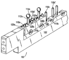
FIG. 4 is a broken perspective view of a die plate according to the invention; and
FIG. 5 is a side elevational view orthogonal to FIG. 3.
DETAILED DESCRIPTION OF THE PREFERRED EMBODIMENTS
Referring now to FIGS. 3 through 5, a die plate 100 according to the invention includes an aluminum subframe 102 with a split stainless steel die station 104. The die station 104 has a lower member 106 and a plurality of removable upper members 108 a-108 p. The die holes 110 a-110 p are aligned with their diameters collinear with the parting line between the upper members 108 a-108 p and the lower member 106. According to the presently preferred embodiment, each upper member 108 a-108 p is associated with a single die hole 110 a-110 p, half of which is defined by the upper member and the other half of which is defined by the lower member. Each upper member is preferably provided with an insulated handle 112 a-112 p and the lower member is preferably provided with a plurality of clamps, e.g. 114 a seen in FIGS. 4 and 5, for clamping the upper members in position. The clamps are each provided with an insulated release handle 116 a.
The upper and lower members are preferably provided with mating pins and holes for rapid alignment. As illustrated, the lower member 106 has a pair of upstanding pins, 118 a, 118 a′ through 118 p, 118 p′, for each upper member. Each upper member has a corresponding pair of holes 120 a, 120 a′ through 120 p, 120 p′.
The die plate 100 according to the invention is easily threaded by unclamping an upper member 108 from the lower member 106, removing the upper member, laying wick material in the lower half of the die hole defined by the lower member (see e.g. 110C in FIG. 4), and then replacing the upper member 108. The stainless steel material used for the die plate 106, 108 is highly wear resistant and the wicks produced with it have a consistent diameter. In addition to saving considerable time during normal threading operations, the split die plates of the invention provide other unexpected advantages. For example, if a wick string breaks upstream from the die, it can be repaired with a knot and the upper member of the die can be lifted momentarily to allow the knot to pass.
There has been described and illustrated herein a multi-part candle wick die plate. While particular embodiments of the invention have been described, it is not intended that the invention be limited thereto, as it is intended that the invention be as broad in scope as the art will allow and that the specification be read likewise. It will therefore be appreciated by those skilled in the art that yet other modifications could be made to the provided invention without deviating from its spirit and scope as so claimed.

Claims (7)

What is claimed is:
1. A candle wick die plate, comprising:
a) lower member defining a plurality of lower approximately 180° of die holes;
b) a plurality of upper members each defining an upper approximately 180° of a die hole; and
c) means for releasably attaching said upper members to said lower member whereby when attached, said upper and lower members define a plurality of complete die holes.
2. A candle wick die plate according to claim 1, further comprising:
d) a plurality of handles, each coupled to a respective upper member.
3. A candle wick die plate according to claim 1, wherein:
said complete die holes are tapered.
4. A candle wick die plate according to claim 1, wherein:
said upper members and said lower member are stainless steel.
5. A candle wick die plate according to claim 4, further comprising:
d) an aluminum subframe supporting said lower member.
6. A candle wick die plate according to claim 1, wherein:
said means for releasably attaching includes a plurality of releasable clamps.
7. A candle wick die plate according to claim 1, wherein:
one of each said upper member and said lower member has a pair of mating pins, and
the other of each said upper member and said lower member defines a pair of mating holes for receiving said pins.
US09/584,043 2000-05-30 2000-05-30 Multi-part candle wick die plates Expired - Fee Related US6481997B1 (en)

Priority Applications (1)

Application Number Priority Date Filing Date Title
US09/584,043 US6481997B1 (en) 2000-05-30 2000-05-30 Multi-part candle wick die plates

Applications Claiming Priority (1)

Application Number Priority Date Filing Date Title
US09/584,043 US6481997B1 (en) 2000-05-30 2000-05-30 Multi-part candle wick die plates

Publications (1)

Publication Number Publication Date
US6481997B1 true US6481997B1 (en) 2002-11-19

Family

ID=24335679

Family Applications (1)

Application Number Title Priority Date Filing Date
US09/584,043 Expired - Fee Related US6481997B1 (en) 2000-05-30 2000-05-30 Multi-part candle wick die plates

Country Status (1)

Country Link
US (1) US6481997B1 (en)

Citations (13)

* Cited by examiner, † Cited by third party
Publication number Priority date Publication date Assignee Title
US280566A (en) * 1883-07-03 Candle-mold
US305787A (en) * 1884-09-30 brelivet
US488752A (en) * 1892-12-27 Confectioner s tool
US873073A (en) * 1907-05-02 1907-12-10 Conrad Nordfors Machine for molding candles.
US1168433A (en) * 1915-09-13 1916-01-18 Emil Seiter Candle-mold.
US1630922A (en) * 1922-02-06 1927-05-31 Boston Insulated Wire & Cable Apparatus for the manufacture of electric wires
US1899907A (en) * 1930-11-22 1933-02-28 Acushnet Process Company Apparatus for balanced molding of rubber articles
US2468539A (en) * 1947-02-20 1949-04-26 Carl R Berger Candle molding apparatus
US3568246A (en) * 1968-08-05 1971-03-09 Mandrel Industries Apparatus for molding improved bulkheads for seismic streamers and the like
US3907245A (en) * 1972-08-29 1975-09-23 Fibre Glass Evercoat Co Plastic, two piece candle mold with integral fastening means
US4188009A (en) * 1978-05-15 1980-02-12 Gillespie Albert C Apparatus for molding crayons and the like
US4537570A (en) * 1981-03-12 1985-08-27 Pemco-Kalamazoo, Inc. Lifting apparatus for an injection mold
US5795596A (en) * 1996-02-07 1998-08-18 Acushnet Company Compression mold with rubber shims

Patent Citations (13)

* Cited by examiner, † Cited by third party
Publication number Priority date Publication date Assignee Title
US280566A (en) * 1883-07-03 Candle-mold
US305787A (en) * 1884-09-30 brelivet
US488752A (en) * 1892-12-27 Confectioner s tool
US873073A (en) * 1907-05-02 1907-12-10 Conrad Nordfors Machine for molding candles.
US1168433A (en) * 1915-09-13 1916-01-18 Emil Seiter Candle-mold.
US1630922A (en) * 1922-02-06 1927-05-31 Boston Insulated Wire & Cable Apparatus for the manufacture of electric wires
US1899907A (en) * 1930-11-22 1933-02-28 Acushnet Process Company Apparatus for balanced molding of rubber articles
US2468539A (en) * 1947-02-20 1949-04-26 Carl R Berger Candle molding apparatus
US3568246A (en) * 1968-08-05 1971-03-09 Mandrel Industries Apparatus for molding improved bulkheads for seismic streamers and the like
US3907245A (en) * 1972-08-29 1975-09-23 Fibre Glass Evercoat Co Plastic, two piece candle mold with integral fastening means
US4188009A (en) * 1978-05-15 1980-02-12 Gillespie Albert C Apparatus for molding crayons and the like
US4537570A (en) * 1981-03-12 1985-08-27 Pemco-Kalamazoo, Inc. Lifting apparatus for an injection mold
US5795596A (en) * 1996-02-07 1998-08-18 Acushnet Company Compression mold with rubber shims

Similar Documents

Publication Publication Date Title
KR101975202B1 (en) apparatus for manufacturing split stopper for steel rod coupler
US6481997B1 (en) Multi-part candle wick die plates
EP0144280A2 (en) Tube flaring tool die assembly
US2326305A (en) Practice drum
KR101847146B1 (en) accessory ring manufacturing apparatus and the method of manufacturing accessory ring
ATE424471T1 (en) METHOD AND DEVICE FOR GUIDING AND TANGLING A MULTIFILE THREAD
JPS63268510A (en) Double row wire drawing machine
CN112677096A (en) Pin pulling device suitable for interference fit locating pin
CN207502783U (en) A kind of optical cable helps stripping device
JP2518794Y2 (en) Base for split type coating device
JPH0240720B2 (en)
US2482841A (en) Method of making stretching machine jaws
ATE226489T1 (en) DEVICE FOR CLEANING WIRE FOR PRODUCING DRAWED METAL WIRES
DE69009310T2 (en) Clamping device for the production of nails.
JPH08231999A (en) Production of decorative leather and decorative leather
DE60209975T2 (en) Clamping device for removing bearing rings
US1840486A (en) Cloth clamp
CN107138652A (en) Metal wire unwrapping wire shearing device
JP3639926B2 (en) Wire rod end forming device
US1634752A (en) Combination die for use in perforating machines
CN103203610A (en) Automatic assembly machine for suture line
KR940002200Y1 (en) Device for making umbrella stick
DE332739C (en) Sewing machine
DE69828790D1 (en) Apparatus and method for making bicomponent filaments using flexible tubing
US867262A (en) Tapping-die.

Legal Events

Date Code Title Description
AS Assignment

Owner name: WICKS UNLIMITED, INC., NEW YORK

Free format text: ASSIGNMENT OF ASSIGNORS INTEREST;ASSIGNORS:CAMPBELL, BRUCE M.;SABLOWSKI, HERSHELL P.;REEL/FRAME:010833/0019

Effective date: 20000526

AS Assignment

Owner name: EDWIN B. STIMPSON COMPANY, INC., NEW YORK

Free format text: ASSIGNMENT OF ASSIGNORS INTEREST;ASSIGNOR:WICKS UNLIMITED, INC.;REEL/FRAME:012735/0882

Effective date: 20020222

REMI Maintenance fee reminder mailed
LAPS Lapse for failure to pay maintenance fees
STCH Information on status: patent discontinuation

Free format text: PATENT EXPIRED DUE TO NONPAYMENT OF MAINTENANCE FEES UNDER 37 CFR 1.362

FP Expired due to failure to pay maintenance fee

Effective date: 20061119