US6480143B1 - Electronic identification system - Google Patents
Electronic identification system Download PDFInfo
- Publication number
- US6480143B1 US6480143B1 US09/435,467 US43546799A US6480143B1 US 6480143 B1 US6480143 B1 US 6480143B1 US 43546799 A US43546799 A US 43546799A US 6480143 B1 US6480143 B1 US 6480143B1
- Authority
- US
- United States
- Prior art keywords
- transponder
- signal
- signature
- transponders
- interrogator
- Prior art date
- Legal status (The legal status is an assumption and is not a legal conclusion. Google has not performed a legal analysis and makes no representation as to the accuracy of the status listed.)
- Expired - Lifetime
Links
Images


Classifications
-
- G—PHYSICS
- G06—COMPUTING; CALCULATING OR COUNTING
- G06K—GRAPHICAL DATA READING; PRESENTATION OF DATA; RECORD CARRIERS; HANDLING RECORD CARRIERS
- G06K7/00—Methods or arrangements for sensing record carriers, e.g. for reading patterns
- G06K7/10—Methods or arrangements for sensing record carriers, e.g. for reading patterns by electromagnetic radiation, e.g. optical sensing; by corpuscular radiation
- G06K7/10009—Methods or arrangements for sensing record carriers, e.g. for reading patterns by electromagnetic radiation, e.g. optical sensing; by corpuscular radiation sensing by radiation using wavelengths larger than 0.1 mm, e.g. radio-waves or microwaves
- G06K7/10019—Methods or arrangements for sensing record carriers, e.g. for reading patterns by electromagnetic radiation, e.g. optical sensing; by corpuscular radiation sensing by radiation using wavelengths larger than 0.1 mm, e.g. radio-waves or microwaves resolving collision on the communication channels between simultaneously or concurrently interrogated record carriers.
- G06K7/10029—Methods or arrangements for sensing record carriers, e.g. for reading patterns by electromagnetic radiation, e.g. optical sensing; by corpuscular radiation sensing by radiation using wavelengths larger than 0.1 mm, e.g. radio-waves or microwaves resolving collision on the communication channels between simultaneously or concurrently interrogated record carriers. the collision being resolved in the time domain, e.g. using binary tree search or RFID responses allocated to a random time slot
- G06K7/10059—Methods or arrangements for sensing record carriers, e.g. for reading patterns by electromagnetic radiation, e.g. optical sensing; by corpuscular radiation sensing by radiation using wavelengths larger than 0.1 mm, e.g. radio-waves or microwaves resolving collision on the communication channels between simultaneously or concurrently interrogated record carriers. the collision being resolved in the time domain, e.g. using binary tree search or RFID responses allocated to a random time slot transponder driven
-
- G—PHYSICS
- G06—COMPUTING; CALCULATING OR COUNTING
- G06K—GRAPHICAL DATA READING; PRESENTATION OF DATA; RECORD CARRIERS; HANDLING RECORD CARRIERS
- G06K7/00—Methods or arrangements for sensing record carriers, e.g. for reading patterns
- G06K7/0008—General problems related to the reading of electronic memory record carriers, independent of its reading method, e.g. power transfer
Definitions
- This invention relates to electronic identification systems and more particularly to such a system comprising an interrogator and a plurality of transponders.
- the interrogator comprises a transmitter for transmitting an interrogation signal to a plurality of transponders and a receiver for receiving intermittently repeated discrete response signals from the transponders.
- a microprocessor in. the interrogator reads and identifies a particular transponder from characteristic data in a data stream in the response signal received from that transponder. In a time window immediately after transmission of the response signal, the transponder awaits an acknowledgement from the interrogator indicative of the fact that the transponder has been read by the interrogator.
- the acknowledgement is non-discriminative or non-specific and is provided by the interrogator by a brief interruption of the energizing signal, If the interruption is detected by a transponder during the aforementioned time window associated with that transponder, that transponder accepts that it has been read and it then changes to a sleep mode wherein it does not reply to the interrogator, to enable the interrogator to read other transponders not yet read.
- the probability of collisions in response signals from the plurality of transponders is reduced by utilizing for each transponder a respective randomly generated hold off time after energization by the interrogator has commenced and before the first response signal is transmitted by the transponder; and by causing the response signal to be repeated after randomly generated time periods.
- an electronic identification system comprising an interrogator and a plurality of transponders
- the interrogator comprising:
- transmitter means for transmitting an interrogation signal to the transponders
- each transponder comprising:
- signature generating means for generating a unique signature
- transmitter means for intermittently transmitting in response to the interrogation signal a response signal sing the signature
- the interrogator further comprising acknowledgement signal generating means for generating upon reception of a response signal from one of the transponders, an acknowledgement signal comprising the unique signature of the transponder to be transmitted by transmitter means of the interrogator, thereby to acknowledge reception of the response signal to said one transponder.
- the transmitter means of the transponder may comprise modulator means for backscatter modulating the interrogation signal with the response signal.
- the transmitter means may include a local carrier generator for generating and transmitting the response signal.
- each transponder may comprise time window generating means to generate a time window immediately after transmission of each of the intermittent response signals; and a controller for causing the transponder to change from a normal operational mode to another mode, if an acknowledgement signal comprising the respective signature is received during said time window.
- the signature generating means may comprise a random number generator and the signature may be in the form of a randomly generated number.
- the generator may be adapted to generate a new signature each time the interrogation signal is received again, after it has been interrupted.
- the random number generator may also be operative to determine a random delay or hold off period after first reception of the interrogation signal and before a first of said intermittent response signals is transmitted.
- the random number generator may also be operative to determine random repetition periods for the intermittent response signals.
- the random number generator may also be operative to generate a divisor for a programmable clock frequency divider of the transponder, from time to time to yield a randomly selected clock frequency for the controller of the transponder.
- the aforementioned acknowledgement signal may also include a command to cause the transponder to switch from the normal operational modes to a selected one of a plurality of other modes.
- an interrogator for use with an electronic identification system also comprising a plurality of transponders; the interrogator comprising:
- transmitter means for transmitting an interrogation signal to the plurality of transponders
- receiver means for receiving response signals originating from the plurality of transponders; each response signal comprising a signature characteristic of a respective transponder from which it originates;
- a controller for processing at least one of the response signals received and for causing an acknowledgement signal comprising the signature to be transmitted.
- transponder comprising:
- receiver means for receiving an interrogation signal
- signature generating means for generating a signature characteristic of the transponder
- transmitter means for transmitting in response to the interrogation signal a response signal comprising the signature characteristic of the transponder
- a controller adapted to cause the transponder to switch from one mode of operation to another, if an acknowledgement signal comprising the signature is received.
- the signature generating means may comprise a random number generator and the signature may thus be in the form of a number.
- the transponder may also comprise time window generating means to generate a time window immediately after transmission of the response signal within which time window the acknowledgement signal is expected.
- the number generator may be operative to determine a delay or hold off period after first reception of the interrogation signal and before the response signal is transmitted.
- the random number generator may be operative to determine random repetition periods for the response signal.
- the random number generator may be operative to generate a divisor for a programmable clock frequency divider of the transponder, from time to time to yield a randomly selected clock frequency for the controller of the transponder.
- transponders causing the transponders to receive the interrogation signal and each intermittently to respond with a response signal comprising a signature characteristic of the transponder;
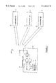
- FIG. 1 is a functional block diagram of an electronic identification system according to the invention comprising an interrogator and a plurality of transponders;
- FIG. 2 is a more detailed block diagram of one of the transponders forming part of the system.
- FIG. 3 is a diagrammatic representation against time of responses from transponders to an interrogation signal and acknowledgement thereof by the interrogator.
- FIG. 1 there is shown an electronic identification system 100 copy an interrogator 10 and a plurality of transponders, transponder # 1 , transponder # 2 and transponder # 3 designated 12 , 14 and 16 respectively which are mounted on or associated with articles (not shown) to be identified or counted.
- the interrogator 10 comprises a transmitter for transmitting an interrogation or energizing signal to the transponders and a receiver 13 for receiving response signals from the transponders.
- a duplex arrangement 15 connects either the transmitter 11 or receiver 13 to antenna 17 .
- the interrogator further comprises a controller 19 and an acknowledgement signal generator 21 , the function of which will be described hereinafter.
- Each transponder 14 , 16 and 18 are similar in configuration and therefore only transponder 14 will be described in more detail hereinafter, with reference to FIG. 2 .
- Each transponder includes a receiver 23 including virtual battery 25 , detector 27 and demodulator 29 .
- the virtual battery captures and stores energy from the energizing signal, to power other circuitry of the transponder.
- other receivers such as super-regenerative, superheterodyne and homodyne receivers may be utilized.
- the aforementioned other circuitry includes a controller 31 including a time window generator 33 which will be referred to hereinafter and a random number generator 35 which will also be referred to hereinafter.
- the random number generator 35 forms part of, or serves or functions as a signature generator 37 for generating a unique signature for the transponder, a repeat period generator 39 for generating a random repeat period (RP) between subsequent repetitions of response signals, a hold-off time-generator 41 for generating a random hold-off time after first reception of the interrogation signal and first transmission of the response signal and a divisor generator 43 for intermittently generating a random divisor for a divider 45 of a clock frequency (f c ) generator 47 forming part of the transponder.
- RP random repeat period
- the transponder further includes a response signal generator 49 for generating a response signal to the interrogation signal and a memory arrangement 53 for storing data.
- the response signal generator forms part of a transmitter 51 for backscatter modulating the interrogation signal via modulator 25 , to transmit the response signals to the interrogator.
- the transponder may comprise a local carrier generator (not shown) for generating and transmitting the response signal.
- the energizing signal is shown at A in FIG. 2 and consequent responses from transponders # 1 to # 3 , are shown at B to D respectively.
- each transponder reflects back to the interrogator intermittent signals 18 comprising some of the energy in the energizing signal by what is known as backscatter modulation and which energy is modulated with data shown in more detail in FIG. 3 .
- the balance of the energy is utilized by virtual battery 25 to power the transponder circuitry, to enable it to perform its functions as herein described.
- the response from each transponder comprises intermittently repeated response signals 18 , each signal comprising start bits 20 , synchronization bits 22 , data bits 24 , a signature or ID code 26 , a CRC error correction code 28 and stop bits 30 .
- the repetition period RP 2 or RP 3 of the signals 18 in the response of each transponder is randomly generated by Motor 39 and is not constant for a transponder.
- each transponder has a respective randomly generated hold-off time (HOLD-OFF 1 to HOLD-OFF 3 ) generated by generator 41 after energization commenced at 32 and before the transponder commences with the response.
- each response signal 18 there is a time window 34 generated by generator 33 during which the respective transponder awaits and is responsive to an acknowledgement signal from the interrogator modulated on the energizing signal in A, that the response signal has been received and read by the interrogator. If the acknowledgement signal is received by the transponder within the time window 34 (see TW 1 in B for transponder # 1 ), the transponder is switched to a mode wherein it does not further respond to the interrogation signal.
- the transponder after the aforementioned randomly generated periods RP 2 in the case of transponder # 2 and RP 3 in the case of transponder # 3 , repeats the response signal as shown at 18 . 1 in C and D, until it is received as hereinbefore described.
- each transponder upon reception of the energization signal, each transponder, after its hold-off time, transmits the response signal 18 .
- the interrogator 10 locks onto the strongest signal received from the plurality of transponders and utilizes the synchronisation bits 22 , to sychronize a dock (not shown) of the interrogator with the clock 47 of the relevant transponder.
- the data 24 is received and stored.
- the interrogator also receives the signature or ID code 26 associated with that transponder.
- the interrogator broadcasts the acknowledgement signal generated by acknowledgement signal generator 21 by modulating the energizing signal A with the ID code 26 just received as shown at 36 in A.
- the transponder associated with that ID code then receives and interprets the acknowledgement and accepts that it has been read by the interrogator and it then switches to a mode wherein it no longer responds to the interrogation signal as shown at B. Since each transponder has a unique ID code, only the transponder actually read will be switched off.
- respective hold-off times (HOLD-OFF 1 to HOLD-OFF 3 ) for transponders # 1 to # 3 are randomly generated by respective random number generators 35 , 44 forming part of each transponder.
- the random number generator 35 , 39 also determines the signal repetition period for each transponder, so that the signal reception period for a particular transponder (RP 2 in the case of transponder # 2 and RP 3 in the case of transponder # 3 ) is not constant, but varies randomly.
- the random number generator 35 , 37 also generates the signature or ID coded 26 for the transponder. The signature remains constant while the transponder remains energized but upon re-energization after an interruption in the energization, the generator generates another random signature.
- the clock speeds of respective transponders may be varied by varying a divisor for a divider 45 in a respective programmable signal generator forming part of the respective transponders.
- the divisor may also be determined by the aforementioned respective random number generator 35 , 43 .
- the interrogator may also transmit a command or signal to cause the transponder just read, to change from its normal operational mode to a selected one of a plurality of other modes, such as a sleep mode for a predetermined short period of time; a sleep mode for a longer period of time; and a mode wherein it no longer responds to the energizing signal, but is able to be switched to the normal operational mode again at any time.
- a command or signal to cause the transponder just read, to change from its normal operational mode to a selected one of a plurality of other modes, such as a sleep mode for a predetermined short period of time; a sleep mode for a longer period of time; and a mode wherein it no longer responds to the energizing signal, but is able to be switched to the normal operational mode again at any time.
Abstract
Description
Claims (17)
Applications Claiming Priority (2)
| Application Number | Priority Date | Filing Date | Title |
|---|---|---|---|
| ZA98/10199 | 1998-11-09 | ||
| ZA9810199 | 1998-11-09 |
Publications (1)
| Publication Number | Publication Date |
|---|---|
| US6480143B1 true US6480143B1 (en) | 2002-11-12 |
Family
ID=25587384
Family Applications (1)
| Application Number | Title | Priority Date | Filing Date |
|---|---|---|---|
| US09/435,467 Expired - Lifetime US6480143B1 (en) | 1998-11-09 | 1999-11-08 | Electronic identification system |
Country Status (8)
| Country | Link |
|---|---|
| US (1) | US6480143B1 (en) |
| EP (1) | EP1001366B1 (en) |
| JP (2) | JP2000230978A (en) |
| CN (1) | CN1255689A (en) |
| AT (1) | ATE289102T1 (en) |
| DE (1) | DE69923645T2 (en) |
| ES (1) | ES2237892T3 (en) |
| ZA (1) | ZA997009B (en) |
Cited By (27)
| Publication number | Priority date | Publication date | Assignee | Title |
|---|---|---|---|---|
| US20030122654A1 (en) * | 2000-05-25 | 2003-07-03 | Tagsys S.A. | Process for detecting simultaneous transmissions from electronic tags |
| US20040085191A1 (en) * | 2000-01-06 | 2004-05-06 | Horwitz Clifford A. | System for multi-standard RFID tags |
| US6745008B1 (en) * | 2000-06-06 | 2004-06-01 | Battelle Memorial Institute K1-53 | Multi-frequency communication system and method |
| US20050169219A1 (en) * | 2004-01-30 | 2005-08-04 | Mark Serpa | Method and system for peer-to-peer wireless communication over unlicensed communication spectrum |
| US6952157B1 (en) * | 2001-05-31 | 2005-10-04 | Alien Technology Corporation | System and method for concurrently addressing multiple radio frequency identification tags from a single reader |
| US20060087406A1 (en) * | 2004-10-26 | 2006-04-27 | Willins Bruce A | System and method for identifying an RFID reader |
| US20070279194A1 (en) * | 2001-10-09 | 2007-12-06 | Curt Carrender | Methods and apparatus for anti-collision for radio frequency communication |
| EP1889089A1 (en) * | 2005-06-03 | 2008-02-20 | Tagent Corporation | Production of radio frequency id tags |
| US20080088414A1 (en) * | 2004-07-29 | 2008-04-17 | Hiroyoshi Suga | Radio-Tag Reading System, Radio-Tag Reader, And Radio Tag |
| US20080204198A1 (en) * | 2007-02-22 | 2008-08-28 | Baohua Qi | RFID sensor array and sensor group based on pulse-processing |
| US20090115582A1 (en) * | 2006-03-23 | 2009-05-07 | Kt Corporation | Apparatus for recognizing radio frequency identification (rfid) and method thereof, and data processing method of rfid |
| US20090124303A1 (en) * | 2000-12-22 | 2009-05-14 | Terahop Networks, Inc. | WIRELESS READER TAGS (WRTs) WITH SENSOR COMPONENTS IN ASSET MONITORING AND TRACKING SYSTEMS |
| US7562083B2 (en) | 2003-11-07 | 2009-07-14 | Alien Technology Corporation | RFID Huffman encoded commands |
| US20100039236A1 (en) * | 2008-08-14 | 2010-02-18 | Greenlee Kenneth L | Time-based operational window for rfid tags |
| US20100328043A1 (en) * | 2008-02-29 | 2010-12-30 | Nokia Corporation | Interrogation of rfid communication units |
| US8072314B1 (en) * | 2004-01-20 | 2011-12-06 | Mistal Software Limited Liability Company | Secondary card reader |
| US8078103B2 (en) | 2005-10-31 | 2011-12-13 | Zih Corp. | Multi-element RFID coupler |
| US8102244B2 (en) | 2003-08-09 | 2012-01-24 | Alien Technology Corporation | Methods and apparatuses to identify devices |
| US8258956B1 (en) | 2004-01-20 | 2012-09-04 | Mistal Software Limited Liability Company | RFID tag filtering and monitoring |
| US8284034B2 (en) | 2001-05-31 | 2012-10-09 | Alien Technology Corporation | Methods and apparatuses to identify devices |
| US20140015647A1 (en) * | 2007-05-15 | 2014-01-16 | John Domokos | Rfid reader |
| US8800871B2 (en) | 2012-03-30 | 2014-08-12 | Microelectronics Technology, Inc. | RFID reader/writer and assembly thereof |
| US20140266629A1 (en) * | 2013-03-14 | 2014-09-18 | Tyco Fire & Security Gmbh | Methods, systems and devices for electronic article surveillance deactivation having randomized transmission rates |
| US20170201005A1 (en) * | 2015-12-17 | 2017-07-13 | Humatics Corporation | Chip-scale radio-frequency localization devices and associated systems and methods |
| US10422870B2 (en) | 2015-06-15 | 2019-09-24 | Humatics Corporation | High precision time of flight measurement system for industrial automation |
| US10509928B2 (en) | 2016-01-29 | 2019-12-17 | Fujifilm Corporation | Information collection system |
| US10591592B2 (en) | 2015-06-15 | 2020-03-17 | Humatics Corporation | High-precision time of flight measurement systems |
Families Citing this family (10)
| Publication number | Priority date | Publication date | Assignee | Title |
|---|---|---|---|---|
| US7011250B2 (en) | 2001-12-20 | 2006-03-14 | Matsushita Electric Industrial Co., Ltd. | IC card reader/writer, identification method and program |
| JP4023308B2 (en) | 2002-12-17 | 2007-12-19 | ソニー株式会社 | Communication apparatus and communication method |
| JP2004215225A (en) | 2002-12-17 | 2004-07-29 | Sony Corp | Communication system, communication method, and data processing device |
| JP4039398B2 (en) * | 2004-06-25 | 2008-01-30 | ソニー株式会社 | Wireless communication system, cradle device, and portable device |
| US20080258864A1 (en) * | 2004-10-28 | 2008-10-23 | Mitsubishi Electeic Corporation | Communication Apparatus and Communication Method |
| JP5729339B2 (en) * | 2012-03-26 | 2015-06-03 | 株式会社デンソーウェーブ | Information media |
| EP2931822B1 (en) | 2012-12-14 | 2021-06-23 | Blue Cube IP LLC | High solids epoxy coatings |
| US9323964B2 (en) | 2013-08-20 | 2016-04-26 | Cubic Corporation | Card detection and selection |
| CN110312094B (en) * | 2019-05-24 | 2021-10-15 | 深圳市朗强科技有限公司 | Signal receiving apparatus, signal output control system, and signal output control method |
| CN112468180A (en) * | 2020-11-12 | 2021-03-09 | 四川九洲空管科技有限责任公司 | Anti-interference response method applied to friend or foe identification system |
Citations (12)
| Publication number | Priority date | Publication date | Assignee | Title |
|---|---|---|---|---|
| US4691202A (en) | 1984-04-03 | 1987-09-01 | Denne Phillip R M | Identification systems |
| EP0467036A2 (en) | 1990-06-15 | 1992-01-22 | Savi Technology, Inc. | Method and apparatus for radio identification and tracking |
| US5189246A (en) | 1989-09-28 | 1993-02-23 | Csir | Timing apparatus |
| US5353009A (en) | 1991-01-04 | 1994-10-04 | Csir | Communication system |
| US5450087A (en) * | 1994-04-06 | 1995-09-12 | Texas Instruments Incorporated | Transponder maintenance mode method |
| EP0694860A2 (en) | 1994-07-27 | 1996-01-31 | Texas Instruments Deutschland Gmbh | Apparatus and method for identifying multiple transponders |
| US5519381A (en) | 1992-11-18 | 1996-05-21 | British Technology Group Limited | Detection of multiple articles |
| US5530702A (en) * | 1994-05-31 | 1996-06-25 | Ludwig Kipp | System for storage and communication of information |
| US5537105A (en) | 1991-01-04 | 1996-07-16 | British Technology Group Limited | Electronic identification system |
| US5557280A (en) | 1992-08-26 | 1996-09-17 | British Technology Group Limited | Synchronized electronic identification system |
| US5566441A (en) | 1993-03-11 | 1996-10-22 | British Technology Group Limited | Attaching an electronic circuit to a substrate |
| US6154136A (en) | 1998-02-26 | 2000-11-28 | Van Eeden; Hendrik Lodewyk | Free running RF identification system with increasing average inter transmission intervals |
Family Cites Families (6)
| Publication number | Priority date | Publication date | Assignee | Title |
|---|---|---|---|---|
| JPH05273338A (en) * | 1992-03-27 | 1993-10-22 | Sharp Corp | Traveling object identifying device |
| JP3051861B2 (en) * | 1992-12-28 | 2000-06-12 | 株式会社豊田中央研究所 | Mobile object identification device |
| JPH08136648A (en) * | 1994-11-07 | 1996-05-31 | Fuji Electric Co Ltd | Traveling object identifying system |
| US5510795A (en) * | 1994-11-10 | 1996-04-23 | Amtech Corporation | Single antenna location and direction finding system |
| JPH09251076A (en) * | 1996-03-15 | 1997-09-22 | Oki Electric Ind Co Ltd | Code generator for transponder |
| JPH10268044A (en) * | 1997-03-21 | 1998-10-09 | Toshiba Corp | Information identification system, controller and responder therefor |
-
1999
- 1999-11-08 US US09/435,467 patent/US6480143B1/en not_active Expired - Lifetime
- 1999-11-09 EP EP99308924A patent/EP1001366B1/en not_active Expired - Lifetime
- 1999-11-09 DE DE69923645T patent/DE69923645T2/en not_active Expired - Lifetime
- 1999-11-09 CN CN99122449A patent/CN1255689A/en active Pending
- 1999-11-09 AT AT99308924T patent/ATE289102T1/en active
- 1999-11-09 JP JP11318426A patent/JP2000230978A/en active Pending
- 1999-11-09 ZA ZA9907009A patent/ZA997009B/en unknown
- 1999-11-09 ES ES99308924T patent/ES2237892T3/en not_active Expired - Lifetime
-
2010
- 2010-05-12 JP JP2010110183A patent/JP5592157B2/en not_active Expired - Lifetime
Patent Citations (17)
| Publication number | Priority date | Publication date | Assignee | Title |
|---|---|---|---|---|
| US4691202A (en) | 1984-04-03 | 1987-09-01 | Denne Phillip R M | Identification systems |
| US5189246A (en) | 1989-09-28 | 1993-02-23 | Csir | Timing apparatus |
| US5282421A (en) | 1989-09-28 | 1994-02-01 | Csir | Timing apparatus |
| US5406890A (en) | 1989-09-28 | 1995-04-18 | Csir | Timing apparatus |
| EP0467036A2 (en) | 1990-06-15 | 1992-01-22 | Savi Technology, Inc. | Method and apparatus for radio identification and tracking |
| US5537105A (en) | 1991-01-04 | 1996-07-16 | British Technology Group Limited | Electronic identification system |
| US5353009A (en) | 1991-01-04 | 1994-10-04 | Csir | Communication system |
| US5699066A (en) | 1992-08-26 | 1997-12-16 | British Technology Group Limited | Synchronized electronic identification system |
| US5557280A (en) | 1992-08-26 | 1996-09-17 | British Technology Group Limited | Synchronized electronic identification system |
| US5519381A (en) | 1992-11-18 | 1996-05-21 | British Technology Group Limited | Detection of multiple articles |
| US5726630A (en) | 1992-11-18 | 1998-03-10 | British Technology Group Limited | Detection of multiple articles |
| US5566441A (en) | 1993-03-11 | 1996-10-22 | British Technology Group Limited | Attaching an electronic circuit to a substrate |
| US5686920A (en) * | 1994-04-06 | 1997-11-11 | Texas Instruments Incorporated | Transponder maintenance mode method |
| US5450087A (en) * | 1994-04-06 | 1995-09-12 | Texas Instruments Incorporated | Transponder maintenance mode method |
| US5530702A (en) * | 1994-05-31 | 1996-06-25 | Ludwig Kipp | System for storage and communication of information |
| EP0694860A2 (en) | 1994-07-27 | 1996-01-31 | Texas Instruments Deutschland Gmbh | Apparatus and method for identifying multiple transponders |
| US6154136A (en) | 1998-02-26 | 2000-11-28 | Van Eeden; Hendrik Lodewyk | Free running RF identification system with increasing average inter transmission intervals |
Cited By (68)
| Publication number | Priority date | Publication date | Assignee | Title |
|---|---|---|---|---|
| US7116212B2 (en) * | 2000-01-06 | 2006-10-03 | Sirit Technologies Inc. | System for multi-standard RFID tags |
| US20040085191A1 (en) * | 2000-01-06 | 2004-05-06 | Horwitz Clifford A. | System for multi-standard RFID tags |
| US20050083180A1 (en) * | 2000-01-06 | 2005-04-21 | Horwitz Clifford A. | System for multi-standard RFID tags |
| US7196613B2 (en) | 2000-01-06 | 2007-03-27 | Sirit Technologies Inc. | System for multi-standard RFID tags |
| US20030122654A1 (en) * | 2000-05-25 | 2003-07-03 | Tagsys S.A. | Process for detecting simultaneous transmissions from electronic tags |
| US6745008B1 (en) * | 2000-06-06 | 2004-06-01 | Battelle Memorial Institute K1-53 | Multi-frequency communication system and method |
| US8326226B2 (en) | 2000-12-22 | 2012-12-04 | Google Inc. | Wake-up in class-based networking |
| US8315563B2 (en) | 2000-12-22 | 2012-11-20 | Google Inc. | Wireless reader tags (WRTs) with sensor components in asset monitoring and tracking systems |
| US8301082B2 (en) | 2000-12-22 | 2012-10-30 | Google Inc. | LPRF device wake up using wireless tag |
| US20090161589A1 (en) * | 2000-12-22 | 2009-06-25 | Terahop Networks, Inc. | Wake-up in class-based networking |
| US8204439B2 (en) | 2000-12-22 | 2012-06-19 | Google Inc. | Wireless reader tags (WRTs) with sensor components in asset monitoring and tracking systems |
| US20110047015A1 (en) * | 2000-12-22 | 2011-02-24 | Twitchell Jr Robert W | Network formation in asset-tracking system based on asset class |
| US20100260087A1 (en) * | 2000-12-22 | 2010-10-14 | Twitchell Jr Robert W | Lprf device wake up using wireless tag |
| US20100130267A1 (en) * | 2000-12-22 | 2010-05-27 | Terahop Networks, Inc. | Lprf device wake up using wireless tag |
| US20090124303A1 (en) * | 2000-12-22 | 2009-05-14 | Terahop Networks, Inc. | WIRELESS READER TAGS (WRTs) WITH SENSOR COMPONENTS IN ASSET MONITORING AND TRACKING SYSTEMS |
| US20090124304A1 (en) * | 2000-12-22 | 2009-05-14 | Terahop Networks, Inc. | WIRELESS READER TAGS (WRTs) WITH SENSOR COMPONENTS IN ASSET MONITORING AND TRACKING SYSTEMS |
| US6952157B1 (en) * | 2001-05-31 | 2005-10-04 | Alien Technology Corporation | System and method for concurrently addressing multiple radio frequency identification tags from a single reader |
| US8284034B2 (en) | 2001-05-31 | 2012-10-09 | Alien Technology Corporation | Methods and apparatuses to identify devices |
| US8279047B2 (en) | 2001-10-09 | 2012-10-02 | Alien Technology Corporation | Methods and apparatus for anti-collision for radio frequency communication |
| US20070279194A1 (en) * | 2001-10-09 | 2007-12-06 | Curt Carrender | Methods and apparatus for anti-collision for radio frequency communication |
| US8742899B2 (en) | 2003-08-09 | 2014-06-03 | Alien Technology Corporation | Methods and apparatuses to identify devices |
| US8102244B2 (en) | 2003-08-09 | 2012-01-24 | Alien Technology Corporation | Methods and apparatuses to identify devices |
| US7716208B2 (en) | 2003-11-07 | 2010-05-11 | Alien Technology Corporation | RFID handshaking |
| US8768952B2 (en) | 2003-11-07 | 2014-07-01 | Alien Technology Corporation | Methods and apparatuses to identify devices |
| US7562083B2 (en) | 2003-11-07 | 2009-07-14 | Alien Technology Corporation | RFID Huffman encoded commands |
| US9483671B2 (en) | 2003-11-07 | 2016-11-01 | Ruizhang Technology Limited Company | Methods and apparatuses to identify devices |
| US7716160B2 (en) | 2003-11-07 | 2010-05-11 | Alien Technology Corporation | Methods and apparatuses to identify devices |
| US8072314B1 (en) * | 2004-01-20 | 2011-12-06 | Mistal Software Limited Liability Company | Secondary card reader |
| US8258956B1 (en) | 2004-01-20 | 2012-09-04 | Mistal Software Limited Liability Company | RFID tag filtering and monitoring |
| US7342895B2 (en) | 2004-01-30 | 2008-03-11 | Mark Serpa | Method and system for peer-to-peer wireless communication over unlicensed communication spectrum |
| US20050169219A1 (en) * | 2004-01-30 | 2005-08-04 | Mark Serpa | Method and system for peer-to-peer wireless communication over unlicensed communication spectrum |
| US7889058B2 (en) * | 2004-07-29 | 2011-02-15 | Mitsubishi Electric Corporation | Radio-tag reading system, radio-tag reader, and radio tag |
| US20080088414A1 (en) * | 2004-07-29 | 2008-04-17 | Hiroyoshi Suga | Radio-Tag Reading System, Radio-Tag Reader, And Radio Tag |
| US20060087406A1 (en) * | 2004-10-26 | 2006-04-27 | Willins Bruce A | System and method for identifying an RFID reader |
| EP1889089A4 (en) * | 2005-06-03 | 2009-01-07 | Tagent Corp | Production of radio frequency id tags |
| EP1889089A1 (en) * | 2005-06-03 | 2008-02-20 | Tagent Corporation | Production of radio frequency id tags |
| US8306474B2 (en) | 2005-10-31 | 2012-11-06 | Zih Corp. | Multi-element RFID coupler |
| US9391675B2 (en) | 2005-10-31 | 2016-07-12 | Zih Corp. | Multi-element RFID coupler |
| US8078103B2 (en) | 2005-10-31 | 2011-12-13 | Zih Corp. | Multi-element RFID coupler |
| US20090115582A1 (en) * | 2006-03-23 | 2009-05-07 | Kt Corporation | Apparatus for recognizing radio frequency identification (rfid) and method thereof, and data processing method of rfid |
| US8395481B2 (en) | 2006-03-23 | 2013-03-12 | Kt Corporation | Apparatus for recognizing radio frequency identification (RFID) and method thereof, and data processing method of RFID |
| US8026795B2 (en) * | 2007-02-22 | 2011-09-27 | Baohua Qi | RFID sensor array and sensor group based on pulse-processing |
| US20080204198A1 (en) * | 2007-02-22 | 2008-08-28 | Baohua Qi | RFID sensor array and sensor group based on pulse-processing |
| US20140015647A1 (en) * | 2007-05-15 | 2014-01-16 | John Domokos | Rfid reader |
| US9141836B2 (en) * | 2007-05-15 | 2015-09-22 | Siemens Aktiengesellschaft | RFID reader |
| US8674808B2 (en) * | 2008-02-29 | 2014-03-18 | Nokia Corporation | Interrogation of RFID communication units |
| US20100328043A1 (en) * | 2008-02-29 | 2010-12-30 | Nokia Corporation | Interrogation of rfid communication units |
| US20100039236A1 (en) * | 2008-08-14 | 2010-02-18 | Greenlee Kenneth L | Time-based operational window for rfid tags |
| US8800871B2 (en) | 2012-03-30 | 2014-08-12 | Microelectronics Technology, Inc. | RFID reader/writer and assembly thereof |
| US20140266629A1 (en) * | 2013-03-14 | 2014-09-18 | Tyco Fire & Security Gmbh | Methods, systems and devices for electronic article surveillance deactivation having randomized transmission rates |
| US9824245B2 (en) * | 2013-03-14 | 2017-11-21 | Tyco Fire & Security Gmbh | Methods, systems and devices for electronic article surveillance deactivation having randomized transmission rates |
| US11237263B2 (en) | 2015-06-15 | 2022-02-01 | Humatics Corporation | High-precision time of flight measurement systems |
| US10422870B2 (en) | 2015-06-15 | 2019-09-24 | Humatics Corporation | High precision time of flight measurement system for industrial automation |
| US10591592B2 (en) | 2015-06-15 | 2020-03-17 | Humatics Corporation | High-precision time of flight measurement systems |
| US10992024B2 (en) | 2015-12-17 | 2021-04-27 | Humatics Corporation | Radio-frequency localization techniques and associated systems, devices, and methods |
| US10665923B2 (en) | 2015-12-17 | 2020-05-26 | Humatics Corporation | Chip-scale radio-frequency localization devices and associated systems and methods |
| US10205218B2 (en) | 2015-12-17 | 2019-02-12 | Humatics Corporation | Radio-frequency localization techniques and associated systems, devices, and methods |
| US10073162B2 (en) | 2015-12-17 | 2018-09-11 | Humatics Corporation | Radio-frequency localization techniques and associated systems, devices, and methods |
| US10505256B2 (en) | 2015-12-17 | 2019-12-10 | Humatics Corporation | Radio-frequency localization techniques and associated systems, devices, and methods |
| US11688929B2 (en) | 2015-12-17 | 2023-06-27 | Humatics Corporation | Radio-frequency localization techniques and associated systems, devices, and methods |
| US10074889B2 (en) * | 2015-12-17 | 2018-09-11 | Humatics Corporation | Chip-scale radio-frequency localization devices and associated systems and methods |
| US10094909B2 (en) | 2015-12-17 | 2018-10-09 | Humantics Corporation | Radio-frequency localization techniques and associated systems, devices, and methods |
| US20170201005A1 (en) * | 2015-12-17 | 2017-07-13 | Humatics Corporation | Chip-scale radio-frequency localization devices and associated systems and methods |
| US11050134B2 (en) | 2015-12-17 | 2021-06-29 | Humatics Corporation | Radio-frequency localization techniques and associated systems, devices, and methods |
| US11050133B2 (en) | 2015-12-17 | 2021-06-29 | Humatics Corporation | Polarization techniques for suppression of harmonic coupling and associated systems, devices, and methods |
| US11177554B2 (en) | 2015-12-17 | 2021-11-16 | Humatics Corporation | Chip-scale radio-frequency localization devices and associated systems and methods |
| US9915725B1 (en) | 2015-12-17 | 2018-03-13 | Humatics Corporation | Radio-frequency localization techniques and associated systems, devices, and methods |
| US10509928B2 (en) | 2016-01-29 | 2019-12-17 | Fujifilm Corporation | Information collection system |
Also Published As
| Publication number | Publication date |
|---|---|
| DE69923645T2 (en) | 2006-03-23 |
| JP2000230978A (en) | 2000-08-22 |
| DE69923645D1 (en) | 2005-03-17 |
| ZA997009B (en) | 2000-05-02 |
| CN1255689A (en) | 2000-06-07 |
| ES2237892T3 (en) | 2005-08-01 |
| JP5592157B2 (en) | 2014-09-17 |
| EP1001366A2 (en) | 2000-05-17 |
| JP2010226745A (en) | 2010-10-07 |
| EP1001366A3 (en) | 2001-11-28 |
| ATE289102T1 (en) | 2005-02-15 |
| EP1001366B1 (en) | 2005-02-09 |
Similar Documents
| Publication | Publication Date | Title |
|---|---|---|
| US6480143B1 (en) | Electronic identification system | |
| EP1017005B1 (en) | A system and method for communicating with multiple transponders | |
| US6784787B1 (en) | Identification system | |
| US6456191B1 (en) | Tag system with anti-collision features | |
| AU745638B2 (en) | Enhanced identification system | |
| US7009495B2 (en) | System and method to identify multiple RFID tags | |
| US5150114A (en) | Polling-type information transmission system | |
| US20020175806A1 (en) | Electronic tag binary selection method | |
| US7498924B2 (en) | Anticollision method that marks the time slots | |
| US7286041B2 (en) | Maintenance of an anticollision channel in an electronic identification system | |
| WO1997017667A9 (en) | Enhanced detection of multiple data transmissions | |
| EP0859989A1 (en) | Enhanced detection of multiple data transmissions | |
| US6150934A (en) | Electronic communication system between a base station and transponders | |
| JPH08167090A (en) | Mobile body discriminating method | |
| CA2266337C (en) | Tag system with anti-collision features | |
| JP3191673B2 (en) | Communication system and transponder for non-contact data reader | |
| JPH0869583A (en) | Moving body discriminating method | |
| JP2938669B2 (en) | Data carrier system | |
| JP3370825B2 (en) | Non-contact transponder recognition method and device | |
| JPH08181633A (en) | Information collection system | |
| WO1999003061A1 (en) | Transmitter, system for remotely recognizing electrically encoded articles, and method therefor | |
| WO2003085843A2 (en) | Transponder-based communication systems |
Legal Events
| Date | Code | Title | Description |
|---|---|---|---|
| AS | Assignment |
Owner name: SUPERSENSOR (PROPRIETARY) LIMITED, SOUTH AFRICA Free format text: ASSIGNMENT OF ASSIGNORS INTEREST;ASSIGNORS:KRUGER, JOHAN DAWID;TURNER, CHRISTOPHER GORDON GERVASE;REEL/FRAME:010543/0579 Effective date: 19991206 |
|
| STCF | Information on status: patent grant |
Free format text: PATENTED CASE |
|
| FEPP | Fee payment procedure |
Free format text: PAT HOLDER NO LONGER CLAIMS SMALL ENTITY STATUS, ENTITY STATUS SET TO UNDISCOUNTED (ORIGINAL EVENT CODE: STOL); ENTITY STATUS OF PATENT OWNER: LARGE ENTITY |
|
| REFU | Refund |
Free format text: REFUND - SURCHARGE, PETITION TO ACCEPT PYMT AFTER EXP, UNINTENTIONAL (ORIGINAL EVENT CODE: R2551); ENTITY STATUS OF PATENT OWNER: LARGE ENTITY |
|
| FPAY | Fee payment |
Year of fee payment: 4 |
|
| SULP | Surcharge for late payment | ||
| AS | Assignment |
Owner name: BTG INTERNATIONAL LIMITED, ENGLAND Free format text: CONFIRMATION OF ASSIGNMENT;ASSIGNOR:SUPERSENSOR (PROPRIETARY) LIMITED;REEL/FRAME:018433/0554 Effective date: 20060807 |
|
| AS | Assignment |
Owner name: ZIH CORP., BERMUDA Free format text: ASSIGNMENT OF ASSIGNORS INTEREST;ASSIGNOR:BTG INTERNATIONAL LIMITED;REEL/FRAME:018463/0029 Effective date: 20060920 |
|
| FEPP | Fee payment procedure |
Free format text: PAYER NUMBER DE-ASSIGNED (ORIGINAL EVENT CODE: RMPN); ENTITY STATUS OF PATENT OWNER: LARGE ENTITY Free format text: PAYOR NUMBER ASSIGNED (ORIGINAL EVENT CODE: ASPN); ENTITY STATUS OF PATENT OWNER: LARGE ENTITY |
|
| FPAY | Fee payment |
Year of fee payment: 8 |
|
| FPAY | Fee payment |
Year of fee payment: 12 |
|
| AS | Assignment |
Owner name: MORGAN STANLEY SENIOR FUNDING, INC. AS THE COLLATERAL AGENT, MARYLAND Free format text: SECURITY AGREEMENT;ASSIGNORS:ZIH CORP.;LASER BAND, LLC;ZEBRA ENTERPRISE SOLUTIONS CORP.;AND OTHERS;REEL/FRAME:034114/0270 Effective date: 20141027 Owner name: MORGAN STANLEY SENIOR FUNDING, INC. AS THE COLLATE Free format text: SECURITY AGREEMENT;ASSIGNORS:ZIH CORP.;LASER BAND, LLC;ZEBRA ENTERPRISE SOLUTIONS CORP.;AND OTHERS;REEL/FRAME:034114/0270 Effective date: 20141027 |
|
| AS | Assignment |
Owner name: JPMORGAN CHASE BANK, N.A., AS THE SUCCESSOR AGENT, NEW YORK Free format text: PATENT SECURITY INTEREST ASSIGNMENT AGREEMENT;ASSIGNOR:MORGAN STANLEY SENIOR FUNDING, INC., AS THE EXISTING AGENT;REEL/FRAME:044791/0842 Effective date: 20170907 Owner name: JPMORGAN CHASE BANK, N.A., AS THE SUCCESSOR AGENT, Free format text: PATENT SECURITY INTEREST ASSIGNMENT AGREEMENT;ASSIGNOR:MORGAN STANLEY SENIOR FUNDING, INC., AS THE EXISTING AGENT;REEL/FRAME:044791/0842 Effective date: 20170907 |
|
| AS | Assignment |
Owner name: ZEBRA TECHNOLOGIES CORPORATION, ILLINOIS Free format text: MERGER;ASSIGNOR:ZIH CORP.;REEL/FRAME:048884/0618 Effective date: 20181220 |
|
| AS | Assignment |
Owner name: JPMORGAN CHASE BANK, N.A., AS COLLATERAL AGENT, NE Free format text: NOTICE OF TRANSFER OF SECURITY INTEREST IN PATENTS;ASSIGNOR:ZEBRA TECHNOLOGIES CORPORATION;REEL/FRAME:049675/0049 Effective date: 20190701 Owner name: JPMORGAN CHASE BANK, N.A., AS COLLATERAL AGENT, NEW YORK Free format text: NOTICE OF TRANSFER OF SECURITY INTEREST IN PATENTS;ASSIGNOR:ZEBRA TECHNOLOGIES CORPORATION;REEL/FRAME:049675/0049 Effective date: 20190701 |