US6464663B1 - Applicator for applying a single—or multicomponent fluid and method for spraying such a fluid - Google Patents
Applicator for applying a single—or multicomponent fluid and method for spraying such a fluid Download PDFInfo
- Publication number
- US6464663B1 US6464663B1 US09/380,844 US38084499A US6464663B1 US 6464663 B1 US6464663 B1 US 6464663B1 US 38084499 A US38084499 A US 38084499A US 6464663 B1 US6464663 B1 US 6464663B1
- Authority
- US
- United States
- Prior art keywords
- spring
- applicator
- gas
- housing
- valve
- Prior art date
- Legal status (The legal status is an assumption and is not a legal conclusion. Google has not performed a legal analysis and makes no representation as to the accuracy of the status listed.)
- Expired - Lifetime
Links
Images


Classifications
-
- B—PERFORMING OPERATIONS; TRANSPORTING
- B05—SPRAYING OR ATOMISING IN GENERAL; APPLYING FLUENT MATERIALS TO SURFACES, IN GENERAL
- B05C—APPARATUS FOR APPLYING FLUENT MATERIALS TO SURFACES, IN GENERAL
- B05C17/00—Hand tools or apparatus using hand held tools, for applying liquids or other fluent materials to, for spreading applied liquids or other fluent materials on, or for partially removing applied liquids or other fluent materials from, surfaces
- B05C17/005—Hand tools or apparatus using hand held tools, for applying liquids or other fluent materials to, for spreading applied liquids or other fluent materials on, or for partially removing applied liquids or other fluent materials from, surfaces for discharging material from a reservoir or container located in or on the hand tool through an outlet orifice by pressure without using surface contacting members like pads or brushes
- B05C17/01—Hand tools or apparatus using hand held tools, for applying liquids or other fluent materials to, for spreading applied liquids or other fluent materials on, or for partially removing applied liquids or other fluent materials from, surfaces for discharging material from a reservoir or container located in or on the hand tool through an outlet orifice by pressure without using surface contacting members like pads or brushes with manually mechanically or electrically actuated piston or the like
- B05C17/0116—Hand tools or apparatus using hand held tools, for applying liquids or other fluent materials to, for spreading applied liquids or other fluent materials on, or for partially removing applied liquids or other fluent materials from, surfaces for discharging material from a reservoir or container located in or on the hand tool through an outlet orifice by pressure without using surface contacting members like pads or brushes with manually mechanically or electrically actuated piston or the like characterised by the piston driving means
- B05C17/0133—Nut and bolt advancing mechanism, e.g. threaded piston rods
-
- A—HUMAN NECESSITIES
- A61—MEDICAL OR VETERINARY SCIENCE; HYGIENE
- A61B—DIAGNOSIS; SURGERY; IDENTIFICATION
- A61B17/00—Surgical instruments, devices or methods, e.g. tourniquets
- A61B17/00491—Surgical glue applicators
-
- A—HUMAN NECESSITIES
- A61—MEDICAL OR VETERINARY SCIENCE; HYGIENE
- A61M—DEVICES FOR INTRODUCING MEDIA INTO, OR ONTO, THE BODY; DEVICES FOR TRANSDUCING BODY MEDIA OR FOR TAKING MEDIA FROM THE BODY; DEVICES FOR PRODUCING OR ENDING SLEEP OR STUPOR
- A61M5/00—Devices for bringing media into the body in a subcutaneous, intra-vascular or intramuscular way; Accessories therefor, e.g. filling or cleaning devices, arm-rests
- A61M5/178—Syringes
- A61M5/31—Details
- A61M5/315—Pistons; Piston-rods; Guiding, blocking or restricting the movement of the rod or piston; Appliances on the rod for facilitating dosing ; Dosing mechanisms
- A61M5/31565—Administration mechanisms, i.e. constructional features, modes of administering a dose
- A61M5/31576—Constructional features or modes of drive mechanisms for piston rods
- A61M5/31578—Constructional features or modes of drive mechanisms for piston rods based on axial translation, i.e. components directly operatively associated and axially moved with plunger rod
- A61M5/31581—Constructional features or modes of drive mechanisms for piston rods based on axial translation, i.e. components directly operatively associated and axially moved with plunger rod performed by rotationally moving or pivoting actuator operated by user, e.g. an injection lever or handle
-
- B—PERFORMING OPERATIONS; TRANSPORTING
- B05—SPRAYING OR ATOMISING IN GENERAL; APPLYING FLUENT MATERIALS TO SURFACES, IN GENERAL
- B05B—SPRAYING APPARATUS; ATOMISING APPARATUS; NOZZLES
- B05B11/00—Single-unit hand-held apparatus in which flow of contents is produced by the muscular force of the operator at the moment of use
- B05B11/01—Single-unit hand-held apparatus in which flow of contents is produced by the muscular force of the operator at the moment of use characterised by the means producing the flow
- B05B11/02—Membranes or pistons acting on the contents inside the container, e.g. follower pistons
-
- B—PERFORMING OPERATIONS; TRANSPORTING
- B05—SPRAYING OR ATOMISING IN GENERAL; APPLYING FLUENT MATERIALS TO SURFACES, IN GENERAL
- B05B—SPRAYING APPARATUS; ATOMISING APPARATUS; NOZZLES
- B05B7/00—Spraying apparatus for discharge of liquids or other fluent materials from two or more sources, e.g. of liquid and air, of powder and gas
- B05B7/24—Spraying apparatus for discharge of liquids or other fluent materials from two or more sources, e.g. of liquid and air, of powder and gas with means, e.g. a container, for supplying liquid or other fluent material to a discharge device
- B05B7/2402—Apparatus to be carried on or by a person, e.g. by hand; Apparatus comprising containers fixed to the discharge device
- B05B7/2467—Apparatus to be carried on or by a person, e.g. by hand; Apparatus comprising containers fixed to the discharge device a liquid being fed by a pressure generated in the container, which is not produced by a carrying fluid
-
- B—PERFORMING OPERATIONS; TRANSPORTING
- B05—SPRAYING OR ATOMISING IN GENERAL; APPLYING FLUENT MATERIALS TO SURFACES, IN GENERAL
- B05C—APPARATUS FOR APPLYING FLUENT MATERIALS TO SURFACES, IN GENERAL
- B05C17/00—Hand tools or apparatus using hand held tools, for applying liquids or other fluent materials to, for spreading applied liquids or other fluent materials on, or for partially removing applied liquids or other fluent materials from, surfaces
- B05C17/005—Hand tools or apparatus using hand held tools, for applying liquids or other fluent materials to, for spreading applied liquids or other fluent materials on, or for partially removing applied liquids or other fluent materials from, surfaces for discharging material from a reservoir or container located in or on the hand tool through an outlet orifice by pressure without using surface contacting members like pads or brushes
- B05C17/00553—Hand tools or apparatus using hand held tools, for applying liquids or other fluent materials to, for spreading applied liquids or other fluent materials on, or for partially removing applied liquids or other fluent materials from, surfaces for discharging material from a reservoir or container located in or on the hand tool through an outlet orifice by pressure without using surface contacting members like pads or brushes with means allowing the stock of material to consist of at least two different components
-
- B—PERFORMING OPERATIONS; TRANSPORTING
- B05—SPRAYING OR ATOMISING IN GENERAL; APPLYING FLUENT MATERIALS TO SURFACES, IN GENERAL
- B05C—APPARATUS FOR APPLYING FLUENT MATERIALS TO SURFACES, IN GENERAL
- B05C17/00—Hand tools or apparatus using hand held tools, for applying liquids or other fluent materials to, for spreading applied liquids or other fluent materials on, or for partially removing applied liquids or other fluent materials from, surfaces
- B05C17/005—Hand tools or apparatus using hand held tools, for applying liquids or other fluent materials to, for spreading applied liquids or other fluent materials on, or for partially removing applied liquids or other fluent materials from, surfaces for discharging material from a reservoir or container located in or on the hand tool through an outlet orifice by pressure without using surface contacting members like pads or brushes
- B05C17/01—Hand tools or apparatus using hand held tools, for applying liquids or other fluent materials to, for spreading applied liquids or other fluent materials on, or for partially removing applied liquids or other fluent materials from, surfaces for discharging material from a reservoir or container located in or on the hand tool through an outlet orifice by pressure without using surface contacting members like pads or brushes with manually mechanically or electrically actuated piston or the like
- B05C17/0116—Hand tools or apparatus using hand held tools, for applying liquids or other fluent materials to, for spreading applied liquids or other fluent materials on, or for partially removing applied liquids or other fluent materials from, surfaces for discharging material from a reservoir or container located in or on the hand tool through an outlet orifice by pressure without using surface contacting members like pads or brushes with manually mechanically or electrically actuated piston or the like characterised by the piston driving means
- B05C17/012—Stepwise advancing mechanism, e.g. pawl and ratchets
- B05C17/0123—Lever actuated
- B05C17/013—Lever actuated comprising a freely rotating element, e.g. a roller, between the lever and a piston rod driving means, e.g. a pawl
-
- A—HUMAN NECESSITIES
- A61—MEDICAL OR VETERINARY SCIENCE; HYGIENE
- A61M—DEVICES FOR INTRODUCING MEDIA INTO, OR ONTO, THE BODY; DEVICES FOR TRANSDUCING BODY MEDIA OR FOR TAKING MEDIA FROM THE BODY; DEVICES FOR PRODUCING OR ENDING SLEEP OR STUPOR
- A61M5/00—Devices for bringing media into the body in a subcutaneous, intra-vascular or intramuscular way; Accessories therefor, e.g. filling or cleaning devices, arm-rests
- A61M5/178—Syringes
- A61M5/31—Details
- A61M5/315—Pistons; Piston-rods; Guiding, blocking or restricting the movement of the rod or piston; Appliances on the rod for facilitating dosing ; Dosing mechanisms
- A61M5/31511—Piston or piston-rod constructions, e.g. connection of piston with piston-rod
- A61M2005/3152—Piston or piston-rod constructions, e.g. connection of piston with piston-rod including gearings to multiply or attenuate the piston displacing force
-
- A—HUMAN NECESSITIES
- A61—MEDICAL OR VETERINARY SCIENCE; HYGIENE
- A61M—DEVICES FOR INTRODUCING MEDIA INTO, OR ONTO, THE BODY; DEVICES FOR TRANSDUCING BODY MEDIA OR FOR TAKING MEDIA FROM THE BODY; DEVICES FOR PRODUCING OR ENDING SLEEP OR STUPOR
- A61M39/00—Tubes, tube connectors, tube couplings, valves, access sites or the like, specially adapted for medical use
- A61M39/22—Valves or arrangement of valves
- A61M39/223—Multiway valves
- A61M2039/224—Multiway valves of the slide-valve type
-
- A—HUMAN NECESSITIES
- A61—MEDICAL OR VETERINARY SCIENCE; HYGIENE
- A61M—DEVICES FOR INTRODUCING MEDIA INTO, OR ONTO, THE BODY; DEVICES FOR TRANSDUCING BODY MEDIA OR FOR TAKING MEDIA FROM THE BODY; DEVICES FOR PRODUCING OR ENDING SLEEP OR STUPOR
- A61M39/00—Tubes, tube connectors, tube couplings, valves, access sites or the like, specially adapted for medical use
- A61M39/22—Valves or arrangement of valves
- A61M2039/226—Spindles or actuating means
-
- A—HUMAN NECESSITIES
- A61—MEDICAL OR VETERINARY SCIENCE; HYGIENE
- A61M—DEVICES FOR INTRODUCING MEDIA INTO, OR ONTO, THE BODY; DEVICES FOR TRANSDUCING BODY MEDIA OR FOR TAKING MEDIA FROM THE BODY; DEVICES FOR PRODUCING OR ENDING SLEEP OR STUPOR
- A61M5/00—Devices for bringing media into the body in a subcutaneous, intra-vascular or intramuscular way; Accessories therefor, e.g. filling or cleaning devices, arm-rests
- A61M5/178—Syringes
- A61M5/31—Details
- A61M5/315—Pistons; Piston-rods; Guiding, blocking or restricting the movement of the rod or piston; Appliances on the rod for facilitating dosing ; Dosing mechanisms
- A61M5/31565—Administration mechanisms, i.e. constructional features, modes of administering a dose
- A61M5/31566—Means improving security or handling thereof
- A61M5/31573—Accuracy improving means
- A61M5/31575—Accuracy improving means using scaling up or down transmissions, e.g. gearbox
Definitions
- the invention relates to an applicator for the application of a single- or multicomponent fluid, particularly of a (single- or multicomponent) tissue glue, and a method for the application of such a fluid by spraying.
- tissue glues for the most various purposes.
- these tissue adhesives are multicomponent tissue adhesives and normally two-component tissue adhesives which are applied by use of special applicators.
- a (medical) gas e.g. O 2
- O 2 a gas that is ejected for atomizing the discharge tissue glued so that the latter can be applied by spraying.
- tissue glue The production costs for tissue glue are not negligible, making it desirable to perform a dosed application of the tissue glue by use of an applicator.
- the quantity of tissue glue ejected per actuation of the applicator should be the same each time.
- an applicator comprising
- At least one supply container for said fluid adapted to be mounted to said housing, said supply container comprising a discharge opening and having arranged therein a piston for sliding displacement in the direction of said discharge opening,
- an energy storage means comprising a hand-operated tensioning lever, pivotally arranged on said housing, which, when moved from a rest position into a pulling position, causes movement of a spring tensioning element by which a spring for storage of mechanical energy, having one end fixed on said housing, can be transferred from a rest position into a tensioned position, and
- a moving means for said piston of said supply container said moving means being coupled to said energy storage means and comprising a drive element coupled to the other end of said spring, said drive element being adapted to be driven, by the stored mechanical energy of said spring during the transfer from the tensioned position into the rest position of said spring, in increments so as to move a press-on element acting on said piston for displacing it in the direction of said discharge opening of said supply container.
- the applicator according to the invention is provided with an energy storage means which is suited for storing mechanical energy which will then be used for dispensing a predetermined quantity of fluid.
- the energy storage means comprises a spring as a mechanical store, which spring can take a rest position and a tensioned position.
- a tensioning lever pivotally supported particularly on a handle member of the housing of the applicator, the spring can be transferred from its rest position to its tensioned position.
- the manually initiated movement of the tensioning lever from the rest position into a pulling position is translated into a movement for transferring the spring from its rest position to its tensioned position.
- a spring tensioning element is arranged between the tensioning lever and the spring for transferring the spring into the tensioned position upon actuation of the tensioning lever.
- the energy storage means has a moving means coupled thereto which comprises a movable press-on element acting on a piston of the storage container accommodating the fluid, for thus slidingly displacing the piston in the direction of the discharge opening of the storage container.
- a moving means coupled thereto which comprises a movable press-on element acting on a piston of the storage container accommodating the fluid, for thus slidingly displacing the piston in the direction of the discharge opening of the storage container.
- the press-on element is moved in increments in the moving direction, while the energy storage means transmitting its stored energy to the drive element each time when the spring moves back from its tensioned position to its rest position.
- the invention provides a simple, mechanically operating mechanism allowing the discharge of fluids in doses and at an exact dosage by use of an applicator.
- an applicator operates in a purely mechanical manner, while the energy respectively required for the discharge of fluid is supplied by a spring which is tensioned by hand.
- the moving means comprises a spindle, secured against axial displacement and supported for rotation on the housing, with the spindle comprising an outer thread in threaded engagement with the inner thread of a through-hole of the press-on element.
- the pivoting movement of the tensioning lever is translated into a rotational movement of the spring tensioning element which for this purpose is supported on the housing for rotation about a rotational axis.
- the spring having one end attached to the housing, has its other end eccentrically coupled to the spring tensioning element.
- the spring tensioning element In the rest position of the spring, the spring tensioning element is in a stable position which hereunder will be referred to as the first dead-center position.
- the spring tensioning element mechanically coupled to the tensioning lever is rotated by slightly more than 180° so that the spring tensioning element is moved slightly beyond its metastabile position displaced by 180° relative to the first dead-center position (hereunder referred to as the second dead-center position).
- Both dead-center positions are defined in that the coupling point between the spring and the spring tensioning element are located on a common line extending in the direction of the length of the spring where also the point of the attachment of the spring on the housing is located.
- the mechanical coupling of the tensioning lever to the spring tensioning element is provided with a freewheeling function so that the tensioning lever can remain pressed when the spring tensioning element is automatically moved due to the spring force.
- a freewheeling function is suitably realized by a toothing on the spring element which extends slightly beyond 180°. This toothing meshes with a toothing of the tensioning lever or with a toothed bar moved by the lever along a linear path, with the tooth on both sides being in mutual engagement for the period of the rotational movement induced by the actuation of the tensioning lever, and then being disengaged.
- the drive element and the spring tensioning element can be arranged as one element which fulfills both the function of the spring tensioning and the function of driving the press-on element.
- the spring tensioning element and drive element is provided with a first toothing for meshing with a toothing of the spring tensioning lever, and with a second toothing provided to engage the toothing of an end-side pinion arranged on the spindle. While the first toothing of the spring tensioning/drive element cooperates with the spring tensioning element when the latter is manually moved from its rest position into the pulling position, the second toothing meshes with the end-side pinion of the spindle within the second half of the rotation of the spring tensioning/drive element. The positioning of this toothing and the number of teeth thereof determine the extent of the rotational movement by which the spindle moves per relaxation of the spring. Also this provides for a setting of the fluid quantity discharged per actuation of the tensioning lever which is obtained through the design.
- both of them are suitably arranged on a common rotational axis so that the rotation of the spring tensioning element is translated into a rotation of the drive element which in turn is used for the advance movement of the press-on element.
- a (medical) gas streams out of a gas discharge opening arranged in the immediate vicinity of the fluid discharge opening of the applicator so that the issued gas will atomize the fluid.
- a gas discharge period during which the gas issues from the gas discharge opening begins prior to the fluid discharge period.
- the gas discharge is already underway when the fluid is discharged from the fluid discharge opening. In this manner, a formation of drops at the beginning of the fluid discharge is prevented.
- gas should also be discharged from the gas discharge opening for a period, although a short one, after termination of the discharge of fluid from the gas discharge opening so that fluid drop possibly still attached to the fluid discharge opening can be deposited in sprayed form.
- the above described timing of gas discharge and fluid discharge in an applicator represents an independent thought which can be put to practice also in applicators of a configuration different from the one described above.
- this inventive thought is independently placed under protection irrespective of the applicator disclosed within the frame of the invention.
- the applicator is preferably provided with a gas discharge means for the controlled discharging of gas within a gas discharge period correlating with the spring-driven step-wise movement of the drive element or the actuating of the tensioning lever.
- the gas discharge period begins earlier than the fluid discharge period during which the press-on element acting on the piston is moved. Further, it is suitable if the gas discharge period ends later than the fluid discharge period.
- the gas discharge means can be controlled by a control element which can be moved along in increments together with the drive element.
- the gas discharge means is controlled by the movement of the spring tensioning element and the drive element, respectively, notably indirectly through the control element.
- the gas discharge means suitably is a valve arranged in a gas conduit and biased into its closing position.
- the valve is provided with an actuating element which is acted on by the control element for moving the valve from its closed position to its opened position. Once the control element does not act anymore on the actuating element, the valve will automatically assume its closed position.
- the gas conduit having the valve arranged therein is arranged to connect a gas source for pressurized gas to a gas discharge opening.
- a gas source for pressurized gas to a gas discharge opening.
- the gas supply system of the inventive applicator comprising the gas discharge means and the gas conduit, is provided with a time-delayed switch-off characteristic, i.e. from the moment that the control element does not act anymore on the actuating element of the valve, gas will nonetheless by discharged from the gas discharge opening for a certain time.
- a time-delayed switch-off characteristic i.e. from the moment that the control element does not act anymore on the actuating element of the valve, gas will nonetheless by discharged from the gas discharge opening for a certain time.
- the gas conduit between the valve and the gas discharge opening is provided with a gas storage chamber for the storage of gas. With each opening of the valve, the storage chamber is first filled with gas before gas will be discharged.
- a second alternative for terminating the gas discharge with a time delay resides in that the valve is moved in a time-delayed manner controlled by the pressure of the gas into its closed position when the control element does not act anymore on the actuating element of the valve.
- the coupling of the control element and the actuating element can then be realized in a simple constructional manner by providing the control element as a cam to be driven by rotation and acting on the actuating element which is realized as a plunger, to thus move the plunger along a linear path against the bias of the valve.
- the cam is suitably rotated by the spring tensioning element and respectively the drive element of the moving means of the applicator.
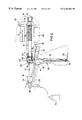
- FIG. 1 is a lateral view of the applicator according to a first embodiment of the invention with the housing shown in vertical section,
- FIG. 2 is a horizontal sectional view of the applicator along the plane II—II in FIG. 1,
- FIG. 3 is a horizontal sectional view of the interior of the applicator along the plane III—III in FIG. 1,
- FIG. 4 is a partial view of the mechanics of the applicator along the plane IV—IV in FIG. 3,
- FIGS. 5 to 7 illustrate several intermediate positions of the individual elements of the mechanics of the applicator, each time seen corresponding to FIG. 4,
- FIG. 8 is a lateral view of an applicator according to a second embodiment of the invention, with the housing shown in vertical section, comprising a valve to be switched into its closed position at a time delay, and
- FIGS. 9 to 12 are sectional views of the valve of the applicator according to FIG. 8 in the closed and opened positions and an intermediate position from which the valve is switched into the closed position at a time delay.
- FIG. 1 is a lateral view of an applicator 10 for discharge of the two-component tissue glue in sprayed form.
- Applicator 10 comprises a housing 12 with a handle 14 .
- the housing accommodates two supply containers in the form of two cylindrical syringe bodies 16 connected to each other through a clamping connection element 18 and held on connection element 18 .
- Each syringe body comprises a piston 20 provided with a stopper 22 and a piston rod 24 extending therefrom.
- the stoppers 22 closely abut the inner wall of the supply containers 16 and are arranged for sliding displacement within the supply containers 16 .
- the supply containers 16 Opposite the piston rods 24 , the supply containers 16 have their front ends provided with respective discharge connecting pieces 28 .
- connection head member 30 Mounted on each of the two discharge connecting pieces 28 is a connection head member 30 having to receiving openings 32 for the discharge connecting pieces 28 .
- the connection head member 30 has a multi-lumen catheter 34 arranged thereon, guided out of housing 12 of applicator 10 via an opening 35 .
- the latter has two mutually separated channels 36 extending therethrough which enter into two lumina of multi-lumen catheter 34 which terminate in discharge openings 34 a , 34 b on the free end of catheter 34 (FIG. 2 ).
- a gas-conducting hose 38 enters into the connection head member 30 .
- a gas-conducting channel 40 extends through the connection head from the entering site of hose 38 to catheter 34 and is flush with a further lumen of catheter 34 which ends in a gas discharge opening 34 c of catheter 34 .
- tissue glue For discharge of tissue glue from applicator 10 , a pressure is exerted against the two pistons in a manner still to be described so that the tissue glue components contained in the syringe bodies 16 are discharged from the discharge openings 34 a , 34 b via connection head member 30 and multi-lumen catheter 34 .
- a medical gas O 2
- gas discharge opening 34 c for thus atomizing and mixing the tissue glue components so that the tissue glue can be sprayed in mixed form.
- applicator 10 comprises a hand-actuated, purely mechanically operating mechanism by which the pistons 20 can be moved in increments in the direction of the syringe bodies 16 .
- This mechanism comprises a mechanical energy storage means 42 and a moving means 44 for step-wise advancement of the pistons 20 .
- Energy storage means 42 comprises a helical tensioning spring 46 having one end 48 attached to a pin 50 arranged within the handle 14 of housing 12 .
- the other end 52 of spring 46 is connected to a connecting arm 53 which is eccentrically supported on a disk-shaped spring tensioning element 54 arranged on an axis 56 supported for rotation on housing 12 .
- Rotatably supported on pin 50 is one end of a substantially U-shaped tensioning lever 58 .
- lever 58 By means of a leg spring 59 extending around pin 50 and supported both on lever 58 and on handle 14 , lever 58 is biased into the starting or rest position shown in FIG. 1 .
- Tensioning lever 58 partially projects from an opening 60 of housing 12 out of handle 14 .
- the angle leg 62 of tensioning lever 58 facing away from pin 50 is provided with a toothing 64 arranged on a slightly curved line with the pin 50 as a center. This toothing 64 meshes with a pinion 67 which together with the spring tensioning element 54 is arranged for rotation on axis 56 .
- Pinion 66 comprises a toothing 68 extending over slightly more than 180° along the circumference of pinion 60 . On the remaining part of the circumference, pinion 66 does not comprise any toothing or teeth.
- Pinion 66 is provided with a further toothing 70 which likewise does not extend fully along the whole circumference of pinion 66 bit instead comprises just a few teeth.
- This toothing 70 meshes with a conical gear 72 attached to one end of spindle 74 .
- Spindle 74 while secured against axial displacement, is supported for rotation in housing 12 as illustrated at 76 .
- Spindle 74 further comprises an outer thread 78 and in this region extends through a through-hole 82 having an inner thread 80 and being arranged in a press-on element 84 which is guided on guide projections 86 of housing 12 and which, upon rotation of the spindle 74 , is moved along a linear path along the guide projections 86 .
- the press-on element 84 abuts a connection element 88 connecting the ends of the piston rods 24 , and via this connection element 88 , acts on the two pistons 20 when the spindle 74 is driven by pinion 66 .
- the axis 56 is provided with a cam 90 (see the representation of the cam 90 in FIGS. 1 and 4) acting on the plunger 92 to advance it linearly and transverse to the extension of the axis 56 .
- the plunger 92 is the actuating member of a valve 94 controlling the gas supply for the discharge of a medicinal gas and being arranged in the gas conduit 38 .
- the gas conduit 38 extends from the outlet 96 of the valve 94 to the connector head 30 .
- the inlet 98 of the valve 94 has a gas conduit 100 connected thereto which is connected to a (external) gas supply indicated at 102 .
- the valve is self-closing, i.e. it is biased towards its closed position.
- a gas reservoir 104 is provided which will be described in more detail below in connection with the description of the functions of the applicator 10 .
- FIGS. 1 and 4 are partial side elevational views of the applicator 10 in the rest position prior to the manual operation of the tensioning lever 58 .
- the spring tensioning element 54 In this rest position, the spring tensioning element 54 is in its lower dead center position in which the coupling point between the spring-loaded connecting arm 53 and the spring tensioning element 54 is on the side of the spring tensioning element 54 that, with regard to its center, faces the pin 50 .
- the tensioning lever 58 By operating the tensioning lever 58 , i.e. by moving the tensioning lever 58 into the handle member 14 , the toothing 64 rotates the pinion 66 and, thereby, the spring tensioning element 54 coupled therewith.
- This rotation of the spring tensioning element 54 caused by the tensioning lever 58 extends over slightly more than 180° (starting from the rotational position of the spring tensioning element 54 illustrated in FIG. 4) so that the coupling point between the spring-loaded connecting arm 53 and the spring tensioning element 54 has passed slightly beyond its upper dead center position.
- the spring 46 Upon reaching the upper dead center position (indicated at 106 bin FIG. 5 ), the spring 46 has the maximum tension and, thus, its maximum stored energy.
- the toothing of the tensioning lever 58 is disengaged from the toothing 68 of the pinion 66 . Due to the spring 46 contracting, the pinion 66 may move freely until the tensioning element 54 again takes its lower dead center position illustrated in FIG. 4 .
- the press-on element 84 is advanced linearly by a certain amount towards the syringe body 16 . This, in turn, causes an amount of two-component tissue glue to be discharged that is defined by the amount of movement of the press-on element 84 and the sectional areas of the syringe bodies 16 .
- the rotation of the pinion 66 also actuates the valve 94 .
- This is effected by the cam 90 arranged on the rotational axis 56 together with the pinion 66 and operating the plunger 92 .
- pressurized gas flows into the gas conduit 38 and first fills the storage chamber 104 . That means that the discharge of the gas from the catheter 34 is delayed in a manner.
- the relative rotational position of the cam 90 with respect to the pinion 66 is selected such that the valve 94 opens just in time before the filing of the storage chamber 104 is completed and gas flows from the catheter 34 before the spindle 74 is turned and the press-on element 84 is advanced linearly.
- FIGS. 8 to 12 a variation of the applicator 10 ′ will be described below.
- the parts of the applicator 10 of FIGS. 1 to 7 correspond to those of the applicator 10 ′, they have been given the same reference numerals in FIG. 8 .
- the two applicator embodiments 10 , 10 ′ differ in that the applicator 10 ′ comprises a valve 94 ′ which, for structure-related reasons, moves from its open position into its closed position with a delay in time.
- the valve 94 ′ comprises a valve housing 108 in which a piston 112 , biased towards its closed position by a pull-back spring 110 , may be advanced and is guided so as to seal against the valve housing 108 .
- the plunger 92 acts on the piston 112 projecting from valve housing 108 .
- the valve housing 108 is provided with the inlet and outlet openings 96 , 98 that are blocked, respectively, by the piston 112 in the closed position illustrated in FIGS. 9 and 12 and between which a gas connection is formed in the open position (FIGS.
- the piston 112 has diametrically opposite edge recesses 114 , 116 , the edge recess 114 facing the outlet opening 98 arranged opposite the inlet opening 96 . Both edge recesses 114 , 116 are connected through a transverse bore 118 in the piston 112 .
- the piston 112 shuts off the outlet opening 98 of the valve housing 108 by positioning the edge recess 116 outside the outlet opening 98 .
- the edge recesses 114 , 116 will coincide with their respective associated inlet and outlet openings 96 , 98 so that a gas flow communication is established via the transverse bore 118 .
- a connection is established between the inlet opening 96 and a gas storage chamber 120 formed in that portion of the valve housing 108 where the enlarged end of the piston 112 abutting the pull-back spring 110 is located.
- this gas storage chamber 120 passes into that portion of the valve housing 108 , in which the portion of the piston 112 having the edge recesses 114 , 116 is located and in which the inlet and outlet openings 96 , 98 are formed.
- the gas storage chamber 120 is connected with the environment of the valve 94 through a bore 124 in the valve housing 108 acting as a throttle.
- the gas storage chamber 120 In the open position, the gas storage chamber 120 is filled with a part of the gas flowing into the valve housing 108 and being discharged via the outlet opening 98 .
- the leak caused by the bore 124 is negligible.
- the piston 112 shuts the gas storage chamber 120 off against the inlet and outlet openings 96 , 98 by means of a seal ring 126 (see FIG. 11 ).
- the gas from the gas storage chamber 120 can only escape through the (throttle) bore 124 , causing a delay in the movement of the piston 112 to its closed position (FIG. 12 ).
- the inlet and outlet openings 96 , 98 are interconnected through the transverse bore 118 so that gas keeps flowing through the valve 94 ′.
- FIGS. 9 to 12 provides a valve with a delayed switching-off, wherein the delay in time is exclusively caused by the gas flow to be switched on and off by the valve. Therefore, no additional control lines or control media are required.
Abstract
Description
Claims (18)
Applications Claiming Priority (3)
| Application Number | Priority Date | Filing Date | Title |
|---|---|---|---|
| DE19709896 | 1997-03-11 | ||
| DE19709896A DE19709896C1 (en) | 1997-03-11 | 1997-03-11 | Applicator for applying a single or multi-component fluid and method for spraying such a fluid |
| PCT/EP1998/001381 WO1998040167A1 (en) | 1997-03-11 | 1998-03-10 | Applicator for applying a single- or multicomponent fluid and method for spraying such a fluid |
Publications (1)
| Publication Number | Publication Date |
|---|---|
| US6464663B1 true US6464663B1 (en) | 2002-10-15 |
Family
ID=7822913
Family Applications (1)
| Application Number | Title | Priority Date | Filing Date |
|---|---|---|---|
| US09/380,844 Expired - Lifetime US6464663B1 (en) | 1997-03-11 | 1998-03-10 | Applicator for applying a single—or multicomponent fluid and method for spraying such a fluid |
Country Status (7)
| Country | Link |
|---|---|
| US (1) | US6464663B1 (en) |
| EP (1) | EP0966330A1 (en) |
| JP (1) | JP2001515401A (en) |
| AU (1) | AU7427198A (en) |
| BR (1) | BR9808323A (en) |
| DE (1) | DE19709896C1 (en) |
| WO (1) | WO1998040167A1 (en) |
Cited By (45)
| Publication number | Priority date | Publication date | Assignee | Title |
|---|---|---|---|---|
| US20020118395A1 (en) * | 2001-02-28 | 2002-08-29 | Brother Kogyo Kabushiki Kaishi | Gear changing device and communication apparatus including the same |
| US20020165483A1 (en) * | 2000-11-10 | 2002-11-07 | Curtis Miller | Gas assisted spray applicator |
| WO2005102538A1 (en) * | 2004-04-22 | 2005-11-03 | Robert Bosch Gmbh | Device for spraying spray fluids |
| WO2006020756A2 (en) * | 2004-08-10 | 2006-02-23 | Allergan, Inc. | Step by step botox injector |
| US20060191962A1 (en) * | 2005-01-12 | 2006-08-31 | Heinz Redl | Hand triggered tissue sealant spray apparatus and system |
| US20070267438A1 (en) * | 2006-05-19 | 2007-11-22 | Horizon Group - Usa, Inc. | Glitter glue tube dispensing apparatus |
| US7441973B2 (en) | 2006-10-20 | 2008-10-28 | Ethicon Endo-Surgery, Inc. | Adhesive applicator |
| US20080272209A1 (en) * | 2007-02-09 | 2008-11-06 | Terumo Kabushiki Kaisha | Sprayer |
| EP1994955A1 (en) * | 2006-03-13 | 2008-11-26 | Terumo Kabushiki Kaisha | Applicator |
| US20080294099A1 (en) * | 2007-05-23 | 2008-11-27 | Terumo Kabushiki Kaisha | Sprayer |
| US20090076458A1 (en) * | 2004-10-21 | 2009-03-19 | Novo Nordisk A/S | Injection Device with Means for Signalling the Time Since the Last Injection |
| US20090124986A1 (en) * | 2007-11-08 | 2009-05-14 | Terumo Kabushiki Kaisha | Sprayer |
| US20090234326A1 (en) * | 2008-03-12 | 2009-09-17 | Terumo Kabushiki Kaisha | Sprayer |
| US7658305B2 (en) | 2006-10-25 | 2010-02-09 | Ethicon Endo-Surgery, Inc. | Adhesive applier with articulating tip |
| US20100072303A1 (en) * | 2008-09-25 | 2010-03-25 | Terumo Kabushiki Kaisha | Sprayer |
| US7749235B2 (en) | 2006-10-20 | 2010-07-06 | Ethicon Endo-Surgery, Inc. | Stomach invagination method and apparatus |
| US20100217231A1 (en) * | 2009-02-20 | 2010-08-26 | Erez Ilan | Device for administering an at least two-component substance |
| US7833216B2 (en) | 2006-11-08 | 2010-11-16 | Ethicon Endo-Surgery, Inc. | Fluid plunger adhesive dispenser |
| US7892250B2 (en) | 2006-11-01 | 2011-02-22 | Ethicon Endo-Surgery, Inc. | Use of biosurgical adhesive on inflatable device for gastric restriction |
| US7914511B2 (en) | 2006-10-18 | 2011-03-29 | Ethicon Endo-Surgery, Inc. | Use of biosurgical adhesive as bulking agent |
| US20110208125A1 (en) * | 2008-08-29 | 2011-08-25 | Novo Nordisk A/S | Medical injection device with time delay indicator |
| WO2011119811A1 (en) * | 2010-03-24 | 2011-09-29 | Nordson Corporation | Gas-assited fluid dispensing device |
| US20110245866A1 (en) * | 2010-04-05 | 2011-10-06 | Neomend, Inc. | Method and apparatus for wound sealant application |
| WO2012012169A1 (en) * | 2010-06-30 | 2012-01-26 | Actamax Surgical Materials, Llc | Self-contained hand-held yoke-connected device for dispensing a two-part adhesive aerosol |
| WO2012023135A1 (en) | 2010-08-19 | 2012-02-23 | Omrix Biopharmaceuticals Ltd. | Device, system and method for dispensing a fixed dose of fluid |
| US8147511B2 (en) | 2003-05-16 | 2012-04-03 | Boston Scientific Scimed, Inc. | Fluid delivery system and related methods of use |
| US20120248152A1 (en) * | 2009-12-09 | 2012-10-04 | Primequal Sa | Ejection device for ejecting small doses |
| US20130264398A1 (en) * | 2012-03-07 | 2013-10-10 | Finishing Brands Holdings Inc | Cordless spray device |
| US8603138B2 (en) | 2006-10-04 | 2013-12-10 | Ethicon Endo-Surgery, Inc. | Use of an adhesive to treat intraluminal bleeding |
| US8608642B2 (en) | 2010-02-25 | 2013-12-17 | Ethicon Endo-Surgery, Inc. | Methods and devices for treating morbid obesity using hydrogel |
| US20140148791A1 (en) * | 2010-04-05 | 2014-05-29 | Neomend, Inc. | Systems, devices, methods for delivering hydrogel compositions with self-purging to prevent clogging |
| US8876844B2 (en) | 2006-11-01 | 2014-11-04 | Ethicon Endo-Surgery, Inc. | Anastomosis reinforcement using biosurgical adhesive and device |
| US20150119814A1 (en) * | 2012-05-25 | 2015-04-30 | Aptar France Sas | Autoinjector comprising a time delay device having a planetary gear set for delaying the retraction of the needle |
| ES2527327R1 (en) * | 2013-07-17 | 2015-05-26 | Aesculap Ag | SPRAY APPLICATOR FOR AN EXPENDING DEVICE FOR SPRAYING A FLUID WITH VARIOUS COMPONENTS AND EXPENDING DEVICE THAT INCLUDES SUCH APPLICATOR |
| US20150148782A1 (en) * | 2013-11-22 | 2015-05-28 | Stemnion, Inc. | Interproximal Drug Delivery Device |
| CN104968442A (en) * | 2012-12-03 | 2015-10-07 | 苏舍米克斯帕克有限公司 | Discharging device |
| US20160030027A1 (en) * | 2010-03-23 | 2016-02-04 | Hyperbranch Medical Technology, Inc. | Disposable syringe applicators for multi-component formulations, and methods of use thereof |
| WO2016188427A1 (en) * | 2015-05-25 | 2016-12-01 | 美敦力公司 | Fluid infusion apparatus comprising mechanical actuating apparatus and manufacturing method for the fluid infusion apparatus |
| US20170070165A1 (en) * | 2011-06-14 | 2017-03-09 | Nemoto Kyorindo Co., Ltd. | Injector and control method for an ultrasonic motor |
| US10751124B2 (en) | 2017-01-05 | 2020-08-25 | Contraline, Inc. | Methods for implanting and reversing stimuli-responsive implants |
| US20210077799A1 (en) * | 2018-04-16 | 2021-03-18 | Renovacare Sciences Corp. | Spray deposition system and its use for treating a living being |
| US20210113301A1 (en) * | 2018-05-04 | 2021-04-22 | 3M Innovative Properties Company | A Dispensing Gun For Dispensing A Dental Material |
| US11253391B2 (en) | 2018-11-13 | 2022-02-22 | Contraline, Inc. | Systems and methods for delivering biomaterials |
| WO2023045592A1 (en) * | 2021-09-27 | 2023-03-30 | 时新(上海)产品设计有限公司 | Micro-dose output structure, micro-dose secretion pump and insulin pump |
| US11904068B2 (en) | 2015-11-12 | 2024-02-20 | University Of Virginia Patent Foundation | Occlusive implant compositions |
Families Citing this family (11)
| Publication number | Priority date | Publication date | Assignee | Title |
|---|---|---|---|---|
| US6783514B2 (en) | 1997-01-31 | 2004-08-31 | United States Surgical Corporation | Fibrin sealant applicator |
| DE19910972C1 (en) * | 1999-03-09 | 2000-10-26 | Omrix Biopharm Sa | Device for applying a flowable medium, in particular a tissue adhesive |
| ES2328087T3 (en) | 2001-02-27 | 2009-11-06 | Tyco Healthcare Group Lp | EXTERNAL MIXING ASSEMBLY. |
| GB0107608D0 (en) | 2001-03-27 | 2001-05-16 | Dca Design Int Ltd | Improvements in and relating to an injection device |
| US6863660B2 (en) | 2002-03-27 | 2005-03-08 | Hapio Biotech, Inc. | Fibrin applicator pistol |
| DE10229731A1 (en) * | 2002-07-02 | 2004-01-15 | Hilti Ag | Squeezing device with dosing device |
| US7217254B2 (en) * | 2002-09-20 | 2007-05-15 | Genzyme Corporation | Multi-pressure biocompatible agent delivery device and method |
| DE10343575B4 (en) * | 2003-09-18 | 2006-06-29 | Hilti Ag | Pressing device with dosing device |
| US7959612B2 (en) * | 2008-04-21 | 2011-06-14 | Medtronic Vascular, Inc. | Dual syringe injector system |
| US8197122B2 (en) * | 2008-04-24 | 2012-06-12 | Tyco Healthcare Group Lp | Dynamic mixing applicator |
| US20140276567A1 (en) * | 2013-03-15 | 2014-09-18 | John Goodman | Device and System for Dispensing a Biological Sealant |
Citations (8)
| Publication number | Priority date | Publication date | Assignee | Title |
|---|---|---|---|---|
| US3782380A (en) | 1973-01-04 | 1974-01-01 | Gaast H V D | Medicament injecting device |
| US4264305A (en) | 1977-03-10 | 1981-04-28 | Rasmussen Jack D | Instrument and method for making dental impressions |
| US4631055A (en) * | 1984-03-29 | 1986-12-23 | Immuno Aktiengesellschaft Fur Chemisch-Medizinische Produkte | Apparatus for applying a tissue adhesive |
| EP0548509A1 (en) | 1991-11-16 | 1993-06-30 | DEUTSCHE TECALEMIT GmbH | Pneumatic gun for applying a pasty material |
| US5263614A (en) | 1992-05-14 | 1993-11-23 | Jacobsen Kenneth H | Material dispensing tool for tubular cartridges |
| US5612050A (en) * | 1993-03-23 | 1997-03-18 | Focal, Inc. | Apparatus and method for local application of polymeric material to tissue |
| US5810885A (en) * | 1994-12-28 | 1998-09-22 | Omrix Biopharm Sa | Device for applying one or several fluids |
| US6234994B1 (en) * | 1996-09-10 | 2001-05-22 | Omrix Biopharmaceuticals Sa | Multicomponent tissue adhesive application device and holder for such device |
Family Cites Families (1)
| Publication number | Priority date | Publication date | Assignee | Title |
|---|---|---|---|---|
| WO1995031138A1 (en) * | 1994-05-12 | 1995-11-23 | Omrix Biopharmaceuticals S.A. | Manually operable device for the simultaneous dispensing of a fluid |
-
1997
- 1997-03-11 DE DE19709896A patent/DE19709896C1/en not_active Expired - Fee Related
-
1998
- 1998-03-10 WO PCT/EP1998/001381 patent/WO1998040167A1/en not_active Application Discontinuation
- 1998-03-10 US US09/380,844 patent/US6464663B1/en not_active Expired - Lifetime
- 1998-03-10 EP EP98921394A patent/EP0966330A1/en not_active Withdrawn
- 1998-03-10 JP JP53921298A patent/JP2001515401A/en active Pending
- 1998-03-10 AU AU74271/98A patent/AU7427198A/en not_active Withdrawn
- 1998-03-10 BR BR9808323-6A patent/BR9808323A/en not_active Application Discontinuation
Patent Citations (8)
| Publication number | Priority date | Publication date | Assignee | Title |
|---|---|---|---|---|
| US3782380A (en) | 1973-01-04 | 1974-01-01 | Gaast H V D | Medicament injecting device |
| US4264305A (en) | 1977-03-10 | 1981-04-28 | Rasmussen Jack D | Instrument and method for making dental impressions |
| US4631055A (en) * | 1984-03-29 | 1986-12-23 | Immuno Aktiengesellschaft Fur Chemisch-Medizinische Produkte | Apparatus for applying a tissue adhesive |
| EP0548509A1 (en) | 1991-11-16 | 1993-06-30 | DEUTSCHE TECALEMIT GmbH | Pneumatic gun for applying a pasty material |
| US5263614A (en) | 1992-05-14 | 1993-11-23 | Jacobsen Kenneth H | Material dispensing tool for tubular cartridges |
| US5612050A (en) * | 1993-03-23 | 1997-03-18 | Focal, Inc. | Apparatus and method for local application of polymeric material to tissue |
| US5810885A (en) * | 1994-12-28 | 1998-09-22 | Omrix Biopharm Sa | Device for applying one or several fluids |
| US6234994B1 (en) * | 1996-09-10 | 2001-05-22 | Omrix Biopharmaceuticals Sa | Multicomponent tissue adhesive application device and holder for such device |
Cited By (85)
| Publication number | Priority date | Publication date | Assignee | Title |
|---|---|---|---|---|
| US20020165483A1 (en) * | 2000-11-10 | 2002-11-07 | Curtis Miller | Gas assisted spray applicator |
| US20020118395A1 (en) * | 2001-02-28 | 2002-08-29 | Brother Kogyo Kabushiki Kaishi | Gear changing device and communication apparatus including the same |
| US8628555B2 (en) | 2003-05-16 | 2014-01-14 | Boston Scientific Scimed, Inc. | Fluid delivery system and related methods of use |
| US8147511B2 (en) | 2003-05-16 | 2012-04-03 | Boston Scientific Scimed, Inc. | Fluid delivery system and related methods of use |
| WO2005102538A1 (en) * | 2004-04-22 | 2005-11-03 | Robert Bosch Gmbh | Device for spraying spray fluids |
| US20080012159A1 (en) * | 2004-04-22 | 2008-01-17 | Robert Bosch Gmbh | Device For Spraying Fluids |
| WO2006020756A2 (en) * | 2004-08-10 | 2006-02-23 | Allergan, Inc. | Step by step botox injector |
| WO2006020756A3 (en) * | 2004-08-10 | 2006-05-04 | Allergan Inc | Step by step botox injector |
| US9314573B2 (en) | 2004-10-21 | 2016-04-19 | Novo Nordisk A/S | Injection device with means for signalling the time since the last injection |
| US20090076458A1 (en) * | 2004-10-21 | 2009-03-19 | Novo Nordisk A/S | Injection Device with Means for Signalling the Time Since the Last Injection |
| EP2514369A1 (en) * | 2005-01-12 | 2012-10-24 | Baxter International Inc. | Hand triggered tissue sealant spray apparatus and system |
| US20110172703A1 (en) * | 2005-01-12 | 2011-07-14 | Baxter International Inc. | Tissue sealant applicator system |
| US7909267B2 (en) * | 2005-01-12 | 2011-03-22 | Baxter International Inc. | Hand triggered tissue sealant spray apparatus and system |
| US8469289B2 (en) * | 2005-01-12 | 2013-06-25 | Baxter International Inc. | Tissue sealant applicator system |
| US20060191962A1 (en) * | 2005-01-12 | 2006-08-31 | Heinz Redl | Hand triggered tissue sealant spray apparatus and system |
| US7537174B2 (en) * | 2005-01-12 | 2009-05-26 | Baxter International Inc. | Hand triggered tissue sealant spray apparatus and system |
| US20090152305A1 (en) * | 2005-01-12 | 2009-06-18 | Baxter International Inc. | Hand triggered tissue sealant spray apparatus and system |
| EP1994955A1 (en) * | 2006-03-13 | 2008-11-26 | Terumo Kabushiki Kaisha | Applicator |
| CN101355982B (en) * | 2006-03-13 | 2010-12-22 | 泰尔茂株式会社 | Applicator |
| US7914484B2 (en) | 2006-03-13 | 2011-03-29 | Terumo Kabushiki Kaisha | Applicator |
| EP1994955A4 (en) * | 2006-03-13 | 2014-12-24 | Terumo Corp | Applicator |
| US20090005731A1 (en) * | 2006-03-13 | 2009-01-01 | Terumo Kabushiki Kaisha | Applicator |
| US20070267438A1 (en) * | 2006-05-19 | 2007-11-22 | Horizon Group - Usa, Inc. | Glitter glue tube dispensing apparatus |
| US8603138B2 (en) | 2006-10-04 | 2013-12-10 | Ethicon Endo-Surgery, Inc. | Use of an adhesive to treat intraluminal bleeding |
| US7914511B2 (en) | 2006-10-18 | 2011-03-29 | Ethicon Endo-Surgery, Inc. | Use of biosurgical adhesive as bulking agent |
| US7441973B2 (en) | 2006-10-20 | 2008-10-28 | Ethicon Endo-Surgery, Inc. | Adhesive applicator |
| US7749235B2 (en) | 2006-10-20 | 2010-07-06 | Ethicon Endo-Surgery, Inc. | Stomach invagination method and apparatus |
| US7658305B2 (en) | 2006-10-25 | 2010-02-09 | Ethicon Endo-Surgery, Inc. | Adhesive applier with articulating tip |
| US7892250B2 (en) | 2006-11-01 | 2011-02-22 | Ethicon Endo-Surgery, Inc. | Use of biosurgical adhesive on inflatable device for gastric restriction |
| US8876844B2 (en) | 2006-11-01 | 2014-11-04 | Ethicon Endo-Surgery, Inc. | Anastomosis reinforcement using biosurgical adhesive and device |
| US7833216B2 (en) | 2006-11-08 | 2010-11-16 | Ethicon Endo-Surgery, Inc. | Fluid plunger adhesive dispenser |
| US20080272209A1 (en) * | 2007-02-09 | 2008-11-06 | Terumo Kabushiki Kaisha | Sprayer |
| US20080294099A1 (en) * | 2007-05-23 | 2008-11-27 | Terumo Kabushiki Kaisha | Sprayer |
| US7846125B2 (en) | 2007-05-23 | 2010-12-07 | Terumo Kabushiki Kaisha | Sprayer |
| US20090124986A1 (en) * | 2007-11-08 | 2009-05-14 | Terumo Kabushiki Kaisha | Sprayer |
| US8545457B2 (en) | 2007-11-08 | 2013-10-01 | Terumo Kabushiki Kaisha | Sprayer |
| US8523806B2 (en) | 2008-03-12 | 2013-09-03 | Terumo Kabushiki Kaisha | Sprayer |
| US20090234326A1 (en) * | 2008-03-12 | 2009-09-17 | Terumo Kabushiki Kaisha | Sprayer |
| US8894611B2 (en) * | 2008-08-29 | 2014-11-25 | Novo Nordisk A/S | Medical injection device with time delay indicator |
| US20110208125A1 (en) * | 2008-08-29 | 2011-08-25 | Novo Nordisk A/S | Medical injection device with time delay indicator |
| US8763933B2 (en) | 2008-09-25 | 2014-07-01 | Terumo Kabushiki Kaisha | Sprayer |
| US20100072303A1 (en) * | 2008-09-25 | 2010-03-25 | Terumo Kabushiki Kaisha | Sprayer |
| US20100217231A1 (en) * | 2009-02-20 | 2010-08-26 | Erez Ilan | Device for administering an at least two-component substance |
| WO2010095128A2 (en) | 2009-02-20 | 2010-08-26 | Omrix Biopharmaceuticals Ltd. | Device for administering an at least two-component substance |
| US20120248152A1 (en) * | 2009-12-09 | 2012-10-04 | Primequal Sa | Ejection device for ejecting small doses |
| US9308057B2 (en) * | 2009-12-09 | 2016-04-12 | Primequal Sa | Ejection device for ejecting small doses |
| US8608642B2 (en) | 2010-02-25 | 2013-12-17 | Ethicon Endo-Surgery, Inc. | Methods and devices for treating morbid obesity using hydrogel |
| US20160030027A1 (en) * | 2010-03-23 | 2016-02-04 | Hyperbranch Medical Technology, Inc. | Disposable syringe applicators for multi-component formulations, and methods of use thereof |
| US20130006170A1 (en) * | 2010-03-24 | 2013-01-03 | Nordson Corporation | Gas-assisted fluid-dispensing device |
| US8603025B2 (en) * | 2010-03-24 | 2013-12-10 | Nordson Corporation | Gas-assisted fluid-dispensing device |
| WO2011119811A1 (en) * | 2010-03-24 | 2011-09-29 | Nordson Corporation | Gas-assited fluid dispensing device |
| US20110245866A1 (en) * | 2010-04-05 | 2011-10-06 | Neomend, Inc. | Method and apparatus for wound sealant application |
| US10987093B2 (en) * | 2010-04-05 | 2021-04-27 | Neomend, Inc. | Method and apparatus for wound sealant application |
| US9662098B2 (en) * | 2010-04-05 | 2017-05-30 | Neomend, Inc. | Systems, devices, methods for delivering hydrogel compositions with self-purging to prevent clogging |
| US20140148791A1 (en) * | 2010-04-05 | 2014-05-29 | Neomend, Inc. | Systems, devices, methods for delivering hydrogel compositions with self-purging to prevent clogging |
| US9211554B2 (en) | 2010-06-30 | 2015-12-15 | Actamax Surgical Materials, Llc | Self-contained hand-held direct drive device for dispensing a two-part adhesive aerosol |
| WO2012012169A1 (en) * | 2010-06-30 | 2012-01-26 | Actamax Surgical Materials, Llc | Self-contained hand-held yoke-connected device for dispensing a two-part adhesive aerosol |
| WO2012012178A1 (en) * | 2010-06-30 | 2012-01-26 | Actamax Surgical Materials, Llc | Self-contained hand-held direct drive for dispensing a two-part adhesive aerosol |
| US8640921B2 (en) | 2010-08-19 | 2014-02-04 | Omrix Biopharmaceuticals Ltd. | Device, system and method for dispensing a fixed dose of fluid |
| WO2012023135A1 (en) | 2010-08-19 | 2012-02-23 | Omrix Biopharmaceuticals Ltd. | Device, system and method for dispensing a fixed dose of fluid |
| US20170070165A1 (en) * | 2011-06-14 | 2017-03-09 | Nemoto Kyorindo Co., Ltd. | Injector and control method for an ultrasonic motor |
| US11303227B2 (en) * | 2011-06-14 | 2022-04-12 | Nemoto Kyorindo Co., Ltd. | Injector and control method for an ultrasonic motor |
| US9149821B2 (en) * | 2012-03-07 | 2015-10-06 | Carlisle Fluid Technologies, Inc. | Cordless spray device |
| CN104321147A (en) * | 2012-03-07 | 2015-01-28 | 博兰智涂装控股公司 | Cordless spray device |
| US20130264398A1 (en) * | 2012-03-07 | 2013-10-10 | Finishing Brands Holdings Inc | Cordless spray device |
| US20150119814A1 (en) * | 2012-05-25 | 2015-04-30 | Aptar France Sas | Autoinjector comprising a time delay device having a planetary gear set for delaying the retraction of the needle |
| US9707343B2 (en) * | 2012-05-25 | 2017-07-18 | Aptar France Sas | Autoinjector comprising a time delay device having a planetary gear set for delaying the retraction of the needle |
| CN104968442A (en) * | 2012-12-03 | 2015-10-07 | 苏舍米克斯帕克有限公司 | Discharging device |
| CN104968442B (en) * | 2012-12-03 | 2017-06-06 | 苏舍米克斯帕克有限公司 | Distributing equipment |
| US9889465B2 (en) | 2012-12-03 | 2018-02-13 | Sulzer Mixpac Ag | Dispensing apparatus |
| ES2527327R1 (en) * | 2013-07-17 | 2015-05-26 | Aesculap Ag | SPRAY APPLICATOR FOR AN EXPENDING DEVICE FOR SPRAYING A FLUID WITH VARIOUS COMPONENTS AND EXPENDING DEVICE THAT INCLUDES SUCH APPLICATOR |
| US20150148782A1 (en) * | 2013-11-22 | 2015-05-28 | Stemnion, Inc. | Interproximal Drug Delivery Device |
| US9802010B2 (en) * | 2013-11-22 | 2017-10-31 | Noveome Biotherapeutics, Inc. | Interproximal drug delivery device |
| WO2016188427A1 (en) * | 2015-05-25 | 2016-12-01 | 美敦力公司 | Fluid infusion apparatus comprising mechanical actuating apparatus and manufacturing method for the fluid infusion apparatus |
| CN106267459A (en) * | 2015-05-25 | 2017-01-04 | 美敦力公司 | Fluid infusion device and manufacture method thereof including mechanical actuation means |
| US11904068B2 (en) | 2015-11-12 | 2024-02-20 | University Of Virginia Patent Foundation | Occlusive implant compositions |
| US10751124B2 (en) | 2017-01-05 | 2020-08-25 | Contraline, Inc. | Methods for implanting and reversing stimuli-responsive implants |
| US20210077799A1 (en) * | 2018-04-16 | 2021-03-18 | Renovacare Sciences Corp. | Spray deposition system and its use for treating a living being |
| US20210113301A1 (en) * | 2018-05-04 | 2021-04-22 | 3M Innovative Properties Company | A Dispensing Gun For Dispensing A Dental Material |
| US11253391B2 (en) | 2018-11-13 | 2022-02-22 | Contraline, Inc. | Systems and methods for delivering biomaterials |
| US11318040B2 (en) | 2018-11-13 | 2022-05-03 | Contraline, Inc. | Systems and methods for delivering biomaterials |
| US11510807B2 (en) | 2018-11-13 | 2022-11-29 | Contraline, Inc. | Systems and methods for delivering biomaterials |
| US11951032B2 (en) | 2018-11-13 | 2024-04-09 | Contraline, Inc. | Systems and methods for delivering biomaterials |
| US11957616B2 (en) | 2018-11-13 | 2024-04-16 | Contraline, Inc. | Systems and methods for delivering biomaterials |
| WO2023045592A1 (en) * | 2021-09-27 | 2023-03-30 | 时新(上海)产品设计有限公司 | Micro-dose output structure, micro-dose secretion pump and insulin pump |
Also Published As
| Publication number | Publication date |
|---|---|
| WO1998040167A1 (en) | 1998-09-17 |
| JP2001515401A (en) | 2001-09-18 |
| DE19709896C1 (en) | 1998-12-24 |
| EP0966330A1 (en) | 1999-12-29 |
| AU7427198A (en) | 1998-09-29 |
| BR9808323A (en) | 2000-05-16 |
Similar Documents
| Publication | Publication Date | Title |
|---|---|---|
| US6464663B1 (en) | Applicator for applying a single—or multicomponent fluid and method for spraying such a fluid | |
| US6565539B1 (en) | Device for applying a flowable medium, notably a tissue adhesive | |
| EP0624403B1 (en) | Dual product dispenser | |
| JP2822269B2 (en) | Volume adjustment mechanism in adhesive dispenser | |
| US10046348B2 (en) | Metering dispenser for discharging an in particular pasty or viscous material, such as cosmetic creams, adhesives and the like | |
| US5190191A (en) | Apparatus for measured and unmeasured dispensing of viscous fluids | |
| US7748567B2 (en) | Single dose dual fluid cartridge for use with hand-held applicators | |
| US7861893B2 (en) | Adhesive dispenser for surgery | |
| US8167835B2 (en) | Single chamber device for drawing in and dispensing components | |
| US9770736B2 (en) | Metering dispenser for discharging an in particular pasty or viscous material, such as cosmetic cream, adhesive, and the like | |
| US8919617B2 (en) | Caulk gun with expansion drive | |
| US4758233A (en) | Cream applicator | |
| KR101371268B1 (en) | Self-contained single dose dual fluid dispenser | |
| US7950549B1 (en) | Powered dispenser with interchangeable cartridges | |
| US20080227052A1 (en) | Dose Delivery System | |
| CA2278797A1 (en) | Disposable foaming razor with combination feed dials | |
| CA2431118A1 (en) | Method and apparatus for applying a medically useful multiple component material | |
| US10433941B2 (en) | Dental solution dispenser and methods of use | |
| NZ572067A (en) | Applicator wherein the distance between the distal end of the lever and housing is dependent on the dose set | |
| JP2010513159A (en) | Discharging or dispensing device and discharging means for the device | |
| WO1992022432A1 (en) | Paste wax applicator | |
| US20110278375A1 (en) | Discharge apparatus having compressed gas support | |
| RU2348013C2 (en) | Multiplex proportioner for minimum quantities | |
| CZ45094A3 (en) | Varnish applicator with a feeding stopper | |
| EP1943026B1 (en) | Device for dispensing doses of fluid substances of variable viscosity and density |
Legal Events
| Date | Code | Title | Description |
|---|---|---|---|
| AS | Assignment |
Owner name: OMRIX BIOPHARMACEUTICALS SA, BELGIUM Free format text: ASSIGNMENT OF ASSIGNORS INTEREST;ASSIGNOR:ZINGER, FREDDY;REEL/FRAME:010366/0500 Effective date: 19990915 |
|
| STCF | Information on status: patent grant |
Free format text: PATENTED CASE |
|
| FEPP | Fee payment procedure |
Free format text: PAYOR NUMBER ASSIGNED (ORIGINAL EVENT CODE: ASPN); ENTITY STATUS OF PATENT OWNER: LARGE ENTITY |
|
| FPAY | Fee payment |
Year of fee payment: 4 |
|
| FEPP | Fee payment procedure |
Free format text: PAT HOLDER NO LONGER CLAIMS SMALL ENTITY STATUS, ENTITY STATUS SET TO UNDISCOUNTED (ORIGINAL EVENT CODE: STOL); ENTITY STATUS OF PATENT OWNER: LARGE ENTITY |
|
| REFU | Refund |
Free format text: REFUND - PAYMENT OF MAINTENANCE FEE, 8TH YR, SMALL ENTITY (ORIGINAL EVENT CODE: R2552); ENTITY STATUS OF PATENT OWNER: LARGE ENTITY |
|
| FPAY | Fee payment |
Year of fee payment: 8 |
|
| FPAY | Fee payment |
Year of fee payment: 12 |