US6450395B1 - Method and apparatus for friction stir welding tubular members - Google Patents
Method and apparatus for friction stir welding tubular members Download PDFInfo
- Publication number
- US6450395B1 US6450395B1 US09/629,675 US62967500A US6450395B1 US 6450395 B1 US6450395 B1 US 6450395B1 US 62967500 A US62967500 A US 62967500A US 6450395 B1 US6450395 B1 US 6450395B1
- Authority
- US
- United States
- Prior art keywords
- support ring
- friction stir
- stir welding
- tubular members
- tubular member
- Prior art date
- Legal status (The legal status is an assumption and is not a legal conclusion. Google has not performed a legal analysis and makes no representation as to the accuracy of the status listed.)
- Expired - Lifetime
Links
Images


Classifications
-
- B—PERFORMING OPERATIONS; TRANSPORTING
- B23—MACHINE TOOLS; METAL-WORKING NOT OTHERWISE PROVIDED FOR
- B23K—SOLDERING OR UNSOLDERING; WELDING; CLADDING OR PLATING BY SOLDERING OR WELDING; CUTTING BY APPLYING HEAT LOCALLY, e.g. FLAME CUTTING; WORKING BY LASER BEAM
- B23K20/00—Non-electric welding by applying impact or other pressure, with or without the application of heat, e.g. cladding or plating
- B23K20/12—Non-electric welding by applying impact or other pressure, with or without the application of heat, e.g. cladding or plating the heat being generated by friction; Friction welding
- B23K20/122—Non-electric welding by applying impact or other pressure, with or without the application of heat, e.g. cladding or plating the heat being generated by friction; Friction welding using a non-consumable tool, e.g. friction stir welding
- B23K20/1245—Non-electric welding by applying impact or other pressure, with or without the application of heat, e.g. cladding or plating the heat being generated by friction; Friction welding using a non-consumable tool, e.g. friction stir welding characterised by the apparatus
-
- B—PERFORMING OPERATIONS; TRANSPORTING
- B23—MACHINE TOOLS; METAL-WORKING NOT OTHERWISE PROVIDED FOR
- B23K—SOLDERING OR UNSOLDERING; WELDING; CLADDING OR PLATING BY SOLDERING OR WELDING; CUTTING BY APPLYING HEAT LOCALLY, e.g. FLAME CUTTING; WORKING BY LASER BEAM
- B23K2101/00—Articles made by soldering, welding or cutting
- B23K2101/04—Tubular or hollow articles
- B23K2101/06—Tubes
Definitions
- the present invention relates to friction stir welding and, more particularly, relates to friction stir welding tubular members.
- Friction stir welding is a relatively new process using a rotating tool having a pin or probe and a shoulder to join two workpieces in a solid state or to repair cracks in a single workpiece.
- a rotating tool having a pin or probe and a shoulder to join two workpieces in a solid state or to repair cracks in a single workpiece.
- the probe 10 a of the rotating tool 10 is plunged by a friction stir welding machine into a workpiece or between the faying faces of two workpieces 12 to produce the required resistance force to generate sufficient frictional heating to form a region of plasticized material.
- the tool 10 is typically tilted at an angle relative to the workpiece or workpieces 12 such that the trailing edge of the tool shoulder 10 b is thrust into and consolidates the plasticized material created as the tool is moved along a path defined by the weld joint to be formed. Upon cooling of the plasticized material, the workpieces are joined along the weld joint. The magnitude of force exerted by the friction stir welding tool must be maintained above a prescribed minimum in order to generate the required frictional heating.
- the force exerted by the friction stir welding tool produces a homogeneous weld joint having approximately 75% of the mechanical properties of the parent material, as opposed to approximately 50% for fusion weld joints.
- the friction stir weld process is applied almost exclusively in straight-line welds.
- moving the friction stir welding tool about the circumference of the workpieces and controlling the depth of the probe in the workpieces become problematic.
- it is also necessary to maintain the tubular members in coaxial alignment which can be particularly difficult when applying a force of sufficient magnitude to generate the required frictional heating to form a region of plasticized material.
- the welding device should be capable of effectively supporting the tubular members during welding. Additionally, the welding device should be capable of effectively translating a friction stir welding tool about the circumference of the tubular members and should be easily adaptable to varying tube geometries and sizes.
- the present invention provides an apparatus for forming a weld joint between abutting ends of first and second tubular members.
- the welding apparatus includes a support ring defining an aperture therethrough.
- the support ring has first and second sides defining a channel therebetween.
- the first side of the support ring defines a plurality of supports spaced about the circumference of the support ring, each of which defines a gripping surface for contacting at least a portion of the exterior surface of the first tubular member to thereby secure the abutting end of the first tubular member at least partially within the aperture of the support ring.
- the second side of the support ring defines a plurality of supports spaced about the circumference of the support ring, each of which defines a gripping surface for contacting at least a portion of the exterior surface of the second tubular member to thereby secure the abutting end of the second tubular member at least partially within the aperture of the support ring adjacent to, and coaxially aligned with, the abutting end of the first tubular member.
- the first-side and second-side supports are slidably mounted to the support ring.
- the apparatus includes a plurality of actuator assemblies secured to the support ring.
- each of the actuator assemblies is in operable communication with one of the supports for urging the support toward and away from the corresponding tubular member to thereby accommodate different diameter tubular members.
- each of the first-side and second-side supports comprises a primary support, an alignment clamp pivotally attached to the primary support, and an actuator assembly in operable communication with the alignment clamp.
- the actuator assembly is selected from a group consisting of a pneumatic actuator arm or a hydraulic actuator arm.
- the welding apparatus includes a least one friction stir welding tool, which is movably and rotatably mounted within the channel defined by the support ring and which projects toward the abutting ends of the first and second tubular members.
- the welding apparatus also includes means, in operable communication with the at least one friction stir welding tool, for rotating the at least one tool, and means, in operable communication with the at least one friction stir welding tool, for moving the at least one tool about the abutting ends of the first and second tubular members to thereby form the weld joint.
- the rotating means comprises a rotatable spindle and a motor in operable communication with the spindle.
- the moving means comprises a drive assembly and a motor in operable communication with the drive assembly, and wherein the drive assembly is selected from a group consisting of a belt drive or a gear drive.
- the welding apparatus includes at least one friction stir weld head movably mounted within the channel of the support ring.
- the at least one weld head includes a motor having a rotatable spindle and a friction stir welding tool rotatably mounted to the spindle of the motor.
- the welding apparatus also includes means, in operable communication with the at least one friction stir weld head, for moving the at least one weld head along a path defined by the channel of the support ring such that the rotating friction stir tool moves along a path defined by the abutting ends of the first and second tubular members to thereby form the weld joint.
- the moving means includes a drive assembly and a motor in operable communication with the drive assembly, and wherein the drive assembly is selected from a group consisting of a belt drive or a gear drive.
- the welding apparatus includes means, in operable communication with the at least one friction stir welding tool, for urging the at least one friction stir welding tool toward and away from the abutting ends of the first and second tubular members in order to modify the force exerted by the friction stir welding tool on the abutting ends of the first and second tubular members.
- the means for urging the at least one friction stir welding tool comprises a drive assembly and a motor, in operable communication with the drive assembly, and wherein the drive assembly is selected from a group consisting of a belt drive or a gear drive.
- the present invention also provides a method of welding the abutting ends of first and second tubular members, including the steps of inserting the abutting end of a first tubular member into an aperture defined by a support ring.
- a plurality of supports defined by a first side of the support ring are moved into contact with at least a portion of the surface of the first tubular member such that the abutting end of the first tubular member is at least partially secured within the aperture defined by the support ring.
- the abutting end of a second tubular member is inserted into the aperture defined by the support ring such that the abutting end of the second tubular member is adjacent to, and coaxially aligned with, the abutting end of the first tubular member.
- a plurality of supports defined by the second side of the support ring are moved into contact with at least a portion of the surface of the second tubular member such that the abutting end of the second tubular member is at least partially secured within the aperture defined by the support ring and in coaxial alignment with the abutting end of the first tubular member.
- the moving steps comprise moving a primary support into contact with at least a portion of the surface of the corresponding tubular member and, thereafter, moving an alignment clamp into contact with at least a portion of the surface of the corresponding tubular member.
- tooling is positioned adjacent to the abutting ends of the first and second tubular members opposite of the friction stir welding tool to support the abutting ends of the first and second tubular members during friction stir welding.
- the method also includes inserting at least one rotating friction stir welding tool into the abutting ends of the first and second tubular members to thereby join the abutting ends of the first and second tubular members by friction stir welding.
- the at least one rotating friction stir welding tool is moved through the first and second tubular members along a path that traces the abutting ends of the first and second tubular members to thereby form a continuous joint about the circumference of the first and second tubular members.
- the at least one friction stir welding tool is withdrawn from the abutting ends of the first and second tubular members after moving the at least one friction stir welding tool through the first and second tubular members.
- a welding device and associated method of manufacture for forming friction stir weld joints in workpieces having curvilinear geometries, such as tubular members.
- the welding device is capable of effectively supporting the tubular members during welding. Additionally, the welding device is capable of effectively translating a friction stir welding tool about the circumference of the tubular members and is easily adaptable to varying tube geometries and sizes.
- FIG. 1 is an elevational view illustrating the joining of two flat workpieces by friction stir welding along a straight-line weld, as is known in the art;
- FIG. 2A is a partially cutaway, end elevational view illustrating a friction stir welding device, according to one embodiment of the present invention
- FIG. 2B is a fragmentary end elevational view illustrating the friction stir weld head of the welding device of FIG. 2A;
- FIG. 3 is a cross-sectional view illustrating the welding apparatus of FIG. 2A along lines 3 — 3 ;
- FIG. 4A is a cross-sectional view of a friction stir welding device illustrating the support ring, first-side support, and second-side support of the welding device, according to one embodiment of the present invention
- FIG. 4B is a cross-sectional view illustrating the support ring of FIG. 4A;
- FIG. 4C is an elevational view illustrating the first-side support and second-side support of FIG. 4A.
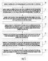
- FIG. 5 is a flow chart illustrating a method for friction stir welding, according to one embodiment of the present invention.
- the friction stir welding device 14 for forming a weld joint between abutting ends of first and second tubular members 16 a, b, such as lengths of tubing.
- the friction stir welding device 14 includes a support ring 18 having first and second sides 18 a, b and defining an aperture 20 therethrough adapted to receive the abutting ends of the first and second tubular members 16 a, b.
- the first and second sides 18 a, b of the support ring define a channel 22 therebetween.
- the support ring 18 is preferably constructed of a metal or metal alloy that has high strength and stiffness, and that is easily machinable. In one embodiment, the support ring is constructed of AISI 17-4PH stainless.
- the support ring 18 can be formed as a unitary ring, but, preferably, as illustrated in FIGS. 2A and 4B, is formed of first and second circular members 21 a, b having a plurality retaining members 23 extending therebetween.
- the number of retaining members 23 extending between the first and second circular members 21 a, b depends upon the diameter of the circular members and the load requirements of the friction stir welding device 14 .
- the plurality of retaining members 23 are equidistantly spaced about the circumference of the first and second circular members 21 a, b.
- Each retaining member 23 includes a pair of alignment pins 15 positioned at either end of the retaining member such that one of the alignment pins 15 a corresponds to the first circular member 21 a and the other alignment pin 15 b corresponds to the second circular member 21 b.
- Each retaining member 23 also defines a pair of threaded apertures 17 a, b corresponding to threaded apertures 19 a, b in the first and second circular members 21 a, b, which receive threaded fasteners, such as bolts, to secure the retaining members to the first and second circular members.
- the support ring is formed of first and second semicircular members having a clam-shell type configuration.
- One end of the first semicircular member is connected to a corresponding end of the second semicircular member by a hinge or the like so that the semicircular members can be rotated relative to each other when aligning and securing the abutting ends of the first and second tubular members within the aperture 20 .
- the other end of the first semicircular member is secured to the corresponding end of the second semicircular member by an interlocking latch once the abutting ends of the first and second tubular members 16 a, b are positioned within the aperture 20 .
- first and second sides 18 a, b of the support ring 18 define a plurality of supports 28 (“first-side supports” 28 a and “second-side supports” 28 b ) spaced along the circumference of the support ring, which extend from the support ring to the first and second tubular members 16 a, b.
- the supports 28 align the abutting ends of the first and second tubular members prior to and during friction stir welding, as well as provide support to the support ring 18 .
- first-side supports 28 a and second-side supports 28 b can be staggered about the circumference of the support ring 18 on opposite sides of the interface defined by the abutting ends of the first and second tubular members 16 a, b, but, preferably, each first-side support 28 a is positioned opposite a corresponding second-side support 28 b.
- Each first-side support 28 a and second-side support 28 b includes first and second ends 29 a, b and defines an elongate raised portion or projection 24 along the side of each support 28 that faces the support ring 18 .
- the projection 24 defined along the side of each support 28 is adapted to be slidably received within a groove 26 defined in the corresponding side 18 a, b of the support ring 18 .
- the support ring 18 includes a plurality of actuator assemblies 35 , each of which includes a motor 35 a, such as an electric, pneumatic or hydraulic motor, that is in operable communication with a corresponding support 28 through an actuator arm 35 a that extends from the motor 35 a to the first end 29 a of the support.
- the motor 35 a is an air cylinder.
- Each actuator assembly 35 is adapted to urge the corresponding support 28 toward and away from the corresponding tubular member 16 a, b by sliding the projection 24 of the support within the groove 26 of the support ring 18 .
- each support 28 preferably includes a primary support 34 , an alignment clamp 36 pivotally attached to the primary support, and an actuator assembly 38 in operable communication with the alignment clamp.
- Each primary support 34 includes a base 34 a adapted to contact the surface of the corresponding tubular member 16 a, b.
- the motors 35 a of the actuator assemblies 35 are preferably controlled by a controller (not shown), which is in operable communication with a sensor corresponding to each of the motors 35 a (not shown), so that the base 34 a of each primary support 34 can be moved in unison into and out of contact with the surface of the corresponding tubular member 16 a, b.
- the controller can include a computer, microprocessor, microcontroller or the like operating under software control.
- the sensors can include a tachometer, digital encoder, dynamometer, pneumatic load cell, hydraulic load cell or the like in operable communication with both the motor 35 a and the controller, as is known in the art.
- the motor 35 a urges the actuator arm 35 b toward the first side 29 a of the corresponding support 28 to thereby urge the support toward the surface of the tubular member.
- the motor 35 urges the actuator arm 35 a away from the first side 29 a of the corresponding support 28 to thereby urge the support away from the surface of the tubular member.
- each primary support 34 includes a flange defining a plurality of teeth that engage the teeth of a corresponding gear.
- the support ring includes a plurality of motors, such as electric, pneumatic or hydraulic motors, each of which is in operable communication with a corresponding gear.
- the motors are preferably controlled by a controller, which is in operable communication with a sensor corresponding to each of the motors, so that the supports 28 can be moved in unison into and out of contact with the surface of the corresponding tubular member 16 a, b.
- the motor turns the corresponding gear counter-clockwise so that the gear engages the teeth of the corresponding flange to thereby urge the support 28 toward the surface of the tubular member.
- the motor turns the corresponding gear clockwise so that the gear engages the teeth of the corresponding flange to thereby urge the support 28 away from the surface of the tubular member.
- Each support 28 has at least one and, preferably, two alignment clamps 36 , each having first and second ends 36 a, b.
- the alignment clamps 36 are pivotally attached to opposite sides of the corresponding primary support 34 through a first pin 40 rotatably mounted within an aperture (not shown) defined by the primary support such that each alignment clamp can be independently operated.
- the first pin 40 is mounted within the aperture of the primary support 34 by one or more low-friction bushings (not shown).
- the first end 36 a of each alignment clamp 36 is rotatably attached to a corresponding actuator assembly 38 . According to one embodiment, as illustrated in FIGS.
- the first end 36 a of each alignment clamp 36 is rotatably attached to the first end 42 a of a corresponding actuator assembly linkage 42 by a second pin 44 .
- the second end 42 b of the actuator assembly linkage 42 is rotatably attached to a pneumatic actuator arm or hydraulic actuator arm of the corresponding actuator assembly 38 by a third pin 46 .
- the actuator assemblies 38 are preferably controlled by a controller (not shown), in operable communication with sensors (not shown), so that the alignment clamps 36 can be moved in unison into and out of contact with the surface of the corresponding tubular member 16 a, b.
- the controller can include a computer, microprocessor, microcontroller or the like operating under software control.
- the sensors can include a pneumatic load cell, hydraulic load cell or the like in operable communication with the controller and the corresponding actuator assembly, as is known in the art.
- the second end 36 b of each alignment clamp 36 defines a gripping surface 36 c for contacting the surface of the corresponding tubular member 16 a, b to coaxially align the abutting ends of the tubular members and secure the abutting ends of the tubular members at least partially within the aperture 20 defined by the support ring 18 .
- each alignment clamp 36 To move the second end 36 b of each alignment clamp 36 into frictional contact with the surface of the corresponding tubular member 16 a, b, the corresponding actuator assembly 38 moves the actuator assembly linkage 42 and the first end 36 a of the alignment clamp away from the support ring 18 thereby pivoting the second end 42 b of the actuator assembly linkage about the third pin 46 , pivoting the first end 36 a of the alignment clamp about the second pin 44 , and pivoting the alignment clamp about the first pin 40 .
- the actuator assembly 38 moves the actuator assembly linkage 42 and the first end 36 a of the alignment clamp toward the support ring 18 thereby pivoting the second end 42 b of the actuator assembly linkage about the third pin 46 , pivoting the first end 36 a of the alignment clamp about the second pin 44 , and pivoting the alignment clamp about the first pin 40 .
- the friction stir welding device 14 includes at least one friction stir welding tool 48 , which is movably and rotatably mounted within the channel 22 defined by the first and second sides 18 a, b of the support ring 18 and which projects toward the abutting ends of the first and second tubular members 16 a, b.
- the friction stir welding device of the present invention can be used to weld tubular members having a wide range of dimension, but, preferably, is used to weld heavy wall tubular members having a diameter of approximately 4 to 16 inches.
- the welding apparatus 14 can include a plurality of friction stir welding tools 48 , which tools preferably are positioned in diametrically opposed pairs about the circumference of the support ring 18 to thereby distribute evenly the loads generated by the friction stir welding process.
- the welding apparatus also includes means, in operable communication with the friction stir welding tool or tools 48 , for rotating the each welding tool, and means, in operable communication with the friction stir welding tool or tools, for moving each welding tool about the abutting ends of the first and second tubular members 16 a, b to thereby form the weld joint.
- the rotating means includes a rotatable spindle 50 and a first motor 52 in operable communication with the spindle and the moving means includes a drive assembly 54 and a second motor 56 in operable communication with the drive assembly.
- the drive assembly 54 can include a belt drive, including a belt or a chain, a gear drive or the like.
- the first and second motors 52 , 56 can include electric, pneumatic or hydraulic motors.
- the first and second motors 52 , 56 are controlled by a controller (not shown), in operable communication with sensors (not shown), so that the friction stir welding tool or tools 48 can be rotated and moved in unison about the circumference of the support ring 18 to form a weld joint.
- the controller can include a computer, microprocessor, microcontroller or the like operating under software control.
- the sensors can include a tachometer, digital encoder, dynamometer, pneumatic load cell, hydraulic load cell or the like in operable communication with the controller and the corresponding motor 52 , 56 , as is known in the art.
- the friction stir welding device 14 includes at least one friction stir weld head 49 movably mounted within the channel 22 of the support ring 18 .
- the friction stir welding device 14 includes a plurality of friction stir welding heads 49 , which heads preferably are positioned in diametrically opposed pairs about the circumference of the support ring 18 to evenly distribute the load generated during the friction stir welding process.
- Each weld head 49 includes a rotatable spindle 50 , a first motor 52 in operable communication with the spindle, and a friction stir welding tool 48 rotatably mounted to the spindle.
- Each weld head preferably includes a hydraulic motor 52 and hydraulic cylinder 52 a.
- the weld-head motor or motors 52 are controlled by a controller (not shown) in operable communication with a sensor (not shown) corresponding to each weld head.
- the friction stir welding device 14 also includes means, in operable communication with the one or more friction stir weld heads 49 , for moving each weld head along a path defined by the channel 22 of the support ring 18 such that the rotating friction stir weld tool 48 moves along a path defined by the abutting ends of the first and second tubular members 16 a, b to thereby form the weld joint.
- the moving means preferably includes a drive assembly 54 and a second motor 56 in operable communication with the drive assembly.
- the drive assembly 54 includes a pair of gears 58 in operable communication with the second motor 56 through a suitable shaft 59 .
- the second motor 56 is a hydraulic motor that supplies an even amount of fluid pressure to two gear motors, each of which corresponds to one of the gears 58 .
- the first and second sides 18 a, b of the support ring 18 each preferably define a recess 60 along the circumference of the support ring that opens into the channel 22 defined between the first and second sides of the support ring.
- Each of the recesses 60 is adapted to receive a corresponding gear 58 and defines a plurality of teeth 60 a that engage teeth 58 a on the outer edge of the gear.
- each weld head is preferably mounted by suitable fasteners (not shown), such as bolts, inside a housing 47 or suitable enclosure that is transported about the circumference of the support ring by the rotation of the pinion gears 58 inside the recesses 60 of the support ring 18 .
- suitable fasteners such as bolts
- each housing 47 preferably has a pair of guide rollers 51 , each of which extends from the housing into a groove 53 defined by the corresponding side of the support ring 18 .
- the welding apparatus 14 includes means, in operable communication with each the friction stir welding tool 48 , for urging the friction stir welding tool toward and away from the abutting ends of the first and second tubular members 16 a, b in order to modify the force exerted by the friction stir welding tool on the abutting ends of the first and second tubular members during friction stir welding.
- the means for urging each friction stir welding tool preferably includes a drive assembly and a motor in operable communication with the drive assembly, and wherein the drive assembly includes a belt drive, gear drive or the like.
- the assignee of the present application has developed an apparatus and associated method for controlling the downforce of the friction stir welding tool during friction stir welding tool, as disclosed in commonly owned U.S. Pat. No. 6,050,475 entitled “Method and Apparatus for Controlling Downforce During Friction Stir Welding,” which issued on Apr. 18, 2000, the entire disclosure of which is hereby incorporated by reference. Additionally, one of the inventors of the present invention has developed an apparatus for adjusting the position of the friction stir welding tool prior to and during friction stir welding, as disclosed in U.S. Pat. No. 5,893,507 entitled “Auto-Adjustable Pin Tool for Friction Stir Welding,” which issued Apr. 13, 1999, the entire disclosure of which is hereby incorporated by reference.
- tooling 37 is positioned adjacent to the abutting ends of the tubular members opposite the friction stir welding tool 48 and the alignment clamps 36 to support the abutting ends of the tubular members during friction stir welding.
- the tooling 37 can be removably positioned within the interior of the tubular members by spot welding the tooling to the surface of the tubular members or by constructing a suitable support structure, as is known in the art.
- the present invention also provides a method of welding the abutting ends of first and second tubular members, including the steps of inserting the abutting end of a first tubular member into an aperture defined by a support ring. See block 70 .
- a plurality of supports defined by a first side of the support ring are moved into friction engagement with at least a portion of the surface of the first tubular member such that the abutting end of the first tubular member is at least partially secured within the aperture defined by the support ring. See block 71 .
- the abutting end of a second tubular member is inserted into the aperture defined by the support ring such that the abutting end of the second tubular member is adjacent to and coaxially aligned with the abutting end of the first tubular member. See block 72 .
- a plurality of supports defined by the second side of the support ring are moved into friction engagement with at least a portion of the surface of the second tubular member such that the abutting end of the second tubular member is at least partially secured within the aperture defined by the support ring. See block 73 .
- At least one rotating friction stir welding tool is inserted into the abutting ends of the first and second tubular members to thereby join the abutting ends of the first and second tubular members by friction stir welding.
- the at least one rotating friction stir welding tool is moved through the first and second tubular members along a path that traces the abutting ends of the first and second tubular members to thereby form a continuous joint about the circumference of the first and second tubular members. See block 75 .
- the at least one friction stir welding tool is withdrawn from the abutting ends of the first and second tubular members after moving the at least one friction stir welding tool through the first and second tubular members. See block 76 .
- a welding device and associated method of manufacture for forming friction stir weld joints in workpieces having curvilinear geometries, such as tubular members.
- the welding device is capable of effectively supporting the tubular members during welding. Additionally, the welding device is capable of effectively translating a friction stir welding tool about the circumference of the tubular members and is easily adaptable to varying tube geometries and sizes.
Abstract
Description
Claims (33)
Priority Applications (1)
| Application Number | Priority Date | Filing Date | Title |
|---|---|---|---|
| US09/629,675 US6450395B1 (en) | 2000-08-01 | 2000-08-01 | Method and apparatus for friction stir welding tubular members |
Applications Claiming Priority (1)
| Application Number | Priority Date | Filing Date | Title |
|---|---|---|---|
| US09/629,675 US6450395B1 (en) | 2000-08-01 | 2000-08-01 | Method and apparatus for friction stir welding tubular members |
Publications (1)
| Publication Number | Publication Date |
|---|---|
| US6450395B1 true US6450395B1 (en) | 2002-09-17 |
Family
ID=24524012
Family Applications (1)
| Application Number | Title | Priority Date | Filing Date |
|---|---|---|---|
| US09/629,675 Expired - Lifetime US6450395B1 (en) | 2000-08-01 | 2000-08-01 | Method and apparatus for friction stir welding tubular members |
Country Status (1)
| Country | Link |
|---|---|
| US (1) | US6450395B1 (en) |
Cited By (51)
| Publication number | Priority date | Publication date | Assignee | Title |
|---|---|---|---|---|
| US20020190101A1 (en) * | 2001-06-04 | 2002-12-19 | Nelson Tracy W. | Apparatus and method for performing non-linear friction stir welds on either planar or non-planar surfaces |
| US20030029903A1 (en) * | 2001-07-30 | 2003-02-13 | Kawasaki Jukogyo Kabushiki Kaisha | Friction stir joining apparatus |
| US6540128B2 (en) * | 2001-04-04 | 2003-04-01 | Hitachi, Ltd. | Friction stir welding method and apparatus, and welded structure |
| WO2004067218A2 (en) * | 2003-01-30 | 2004-08-12 | Smith International, Inc. | Out-of-position stir welding of high melting temperature alloys |
| WO2004091839A2 (en) * | 2003-04-11 | 2004-10-28 | Edison Welding Institute | Method and apparatus for locally clamping components that are to be joined by friction stir welding |
| US20050035179A1 (en) * | 2003-08-12 | 2005-02-17 | The Boeing Company | Stir forming apparatus and method |
| US20050051602A1 (en) * | 2003-05-13 | 2005-03-10 | Babb Jonathan Allyn | Control system for friction stir welding of metal matrix composites, ferrous alloys, non-ferrous alloys, and superalloys |
| US20050082342A1 (en) * | 2003-09-25 | 2005-04-21 | Babb Jonathan A. | Friction stir welding improvements for metal matrix composites, ferrous alloys, non-ferrous alloys, and superalloys using a superabrasive tool |
| US20050133567A1 (en) * | 2003-12-19 | 2005-06-23 | The Boeing Company | Friction welded structural assembly and preform and method for same |
| US20060081683A1 (en) * | 2004-10-05 | 2006-04-20 | Packer Scott M | Expandable mandrel for use in friction stir welding |
| US20060121994A1 (en) * | 2004-12-03 | 2006-06-08 | Douglass David M | Stir welded drive shaft and method of making same |
| WO2007133928A3 (en) * | 2006-05-09 | 2008-11-13 | Noble Drilling Services Inc | Marine riser and method for making |
| US20090134203A1 (en) * | 2007-11-28 | 2009-05-28 | Frank's International, Inc. | Methods and apparatus for forming tubular strings |
| US20090152328A1 (en) * | 2007-12-13 | 2009-06-18 | Hitachi, Ltd. | Apparatus for friction stir and friction stir processing |
| US20090272537A1 (en) * | 2008-05-04 | 2009-11-05 | Alikin Rudolf S | Aluminum riser assembly |
| US20090294514A1 (en) * | 2004-09-27 | 2009-12-03 | Sii Megadiamond, Inc. | Friction stir welding improvements for metal matrix composites, ferrous alloys, non-ferrous alloys, and superalloys using a superabrasive tool |
| US20100006622A1 (en) * | 2008-07-10 | 2010-01-14 | Smith Christopher B | Self-clamping friction stir welding device |
| US20100038408A1 (en) * | 2008-08-14 | 2010-02-18 | Smith International, Inc. | Methods of treating hardbanded joints of pipe using friction stir processing |
| US20100038407A1 (en) * | 2008-08-14 | 2010-02-18 | Smith International, Inc. | Methods of hardbanding joints of pipe using friction stir welding |
| US20100213244A1 (en) * | 2009-02-19 | 2010-08-26 | Ray Miryekta | Modular friction welding head and associated systems and methods |
| US20100219230A1 (en) * | 2005-10-05 | 2010-09-02 | Sii Megadiamond | Expandable mandrel for use in friction stir welding |
| US20100301103A1 (en) * | 2008-02-01 | 2010-12-02 | Saipem S.P.A. | Method and apparatus for the welding of pipes |
| US20100327107A1 (en) * | 2009-02-24 | 2010-12-30 | Blue Origin, Llc | Bidirectional control surfaces for use with high speed vehicles, and associated systems and methods |
| US7866532B1 (en) * | 2010-04-06 | 2011-01-11 | United Launch Alliance, Llc | Friction stir welding apparatus, system and method |
| US20110119914A1 (en) * | 2008-02-29 | 2011-05-26 | Ks Kolbenschmidt Gmbh | Piston For Internal Combustion Engines, Produced By Means of a Multi-Orbital Friction Welding Method |
| US20110127311A1 (en) * | 2009-11-02 | 2011-06-02 | Jeremy Peterson | Out of position friction stir welding of casing and small diameter tubing or pipe |
| US8123104B1 (en) | 2010-04-06 | 2012-02-28 | United Launch Alliance, Llc | Friction welding apparatus, system and method |
| US8141764B1 (en) | 2010-04-06 | 2012-03-27 | United Launch Alliance, Llc | Friction stir welding apparatus, system and method |
| US8397974B2 (en) | 2005-09-26 | 2013-03-19 | Aeroprobe Corporation | Self-reacting friction stir welding tool with the ability to add filler material |
| US8534530B2 (en) | 2011-04-27 | 2013-09-17 | Blue Origin, Llc | Inflatable ring for supporting friction welding workpieces, and associated systems and methods |
| US8550326B2 (en) | 2005-10-05 | 2013-10-08 | Megastir Technologies Llc | Expandable mandrel for use in friction stir welding |
| US8632850B2 (en) | 2005-09-26 | 2014-01-21 | Schultz-Creehan Holdings, Inc. | Friction fabrication tools |
| US8636194B2 (en) | 2005-09-26 | 2014-01-28 | Schultz-Creehan Holdings, Inc. | Friction stir fabrication |
| US8720607B2 (en) | 2010-03-31 | 2014-05-13 | Smith International, Inc. | Downhole tool having a friction stirred surface region |
| US20140151438A1 (en) * | 2012-05-14 | 2014-06-05 | Rodney Dale Fleck | Apparatus to join tubulars using friction stir joining |
| US8783366B2 (en) | 2010-03-31 | 2014-07-22 | Smith International, Inc. | Article of manufacture having a sub-surface friction stir welded channel |
| WO2014120241A1 (en) * | 2013-02-01 | 2014-08-07 | Fluor Technologies Corporation | Friction stir welding devices and methods using tandem tool and anvil |
| CN104384706A (en) * | 2014-11-26 | 2015-03-04 | 哈尔滨工业大学 | Three-layer gas protection cover for titanium and titanium alloy friction stir welding |
| US9061371B2 (en) | 2012-05-14 | 2015-06-23 | Megastir Technologies Llc | Disposable mandrel for friction stir joining |
| CN104722911A (en) * | 2015-02-28 | 2015-06-24 | 江苏科技大学 | Stirring friction welding device and method for track supporting pipeline to be welded |
| US9079674B1 (en) | 2009-09-18 | 2015-07-14 | Blue Origin, Llc | Composite structures for aerospace vehicles, and associated systems and methods |
| CN105057877A (en) * | 2015-08-12 | 2015-11-18 | 宁波金凤焊割机械制造有限公司 | Inner clamp for friction stir welding device of aircraft fuel storage barrel |
| US9266191B2 (en) | 2013-12-18 | 2016-02-23 | Aeroprobe Corporation | Fabrication of monolithic stiffening ribs on metallic sheets |
| US9446476B2 (en) * | 2012-02-09 | 2016-09-20 | Esab Ab | Backing arrangement for use in friction stir welding |
| US9511446B2 (en) | 2014-12-17 | 2016-12-06 | Aeroprobe Corporation | In-situ interlocking of metals using additive friction stir processing |
| US9511445B2 (en) | 2014-12-17 | 2016-12-06 | Aeroprobe Corporation | Solid state joining using additive friction stir processing |
| US20170050263A1 (en) * | 2015-08-21 | 2017-02-23 | Amulaire Thermal Technology, Inc. | Friction stir welding device and method of friction stir welding |
| US20180111221A1 (en) * | 2016-10-21 | 2018-04-26 | Esab Ab | Arcuate boom for friction stir welding of arcuate work pieces |
| US20180161915A1 (en) * | 2016-12-06 | 2018-06-14 | Concurrent Technologies Corporation | Portable friction stir welding repair tool |
| US10286481B2 (en) | 2012-11-05 | 2019-05-14 | Fluor Technologies Corporation | FSW tool with graduated composition change |
| US11311959B2 (en) | 2017-10-31 | 2022-04-26 | MELD Manufacturing Corporation | Solid-state additive manufacturing system and material compositions and structures |
Citations (29)
| Publication number | Priority date | Publication date | Assignee | Title |
|---|---|---|---|---|
| US3266700A (en) | 1964-09-15 | 1966-08-16 | Bauer & Associates Inc | Pipeline welding assembly |
| US3604612A (en) * | 1968-10-01 | 1971-09-14 | Crc Crose Int Inc | Orbital track-traveling carriage mechanism for performing welding and other physical operations |
| US3722778A (en) | 1970-12-14 | 1973-03-27 | North American Rockwell | Tube joining means |
| US3844468A (en) | 1973-06-27 | 1974-10-29 | Crc Crose Int Inc | Universal carriage apparatus for operating on pipes and analogous workpieces of various diameters |
| US3848793A (en) | 1971-11-30 | 1974-11-19 | Gen Motors Corp | Friction welder |
| US3888405A (en) | 1972-09-05 | 1975-06-10 | Production Technology Inc | Quality control apparatus for inertial welding |
| US4067490A (en) | 1974-10-10 | 1978-01-10 | Caterpillar Tractor Co. | Quality control method for inertial welding |
| US4542276A (en) * | 1983-01-20 | 1985-09-17 | Mantra Tube Ltd. | Device for welding tubes |
| US4552609A (en) | 1984-09-24 | 1985-11-12 | Homac Mfg. Company | Method and apparatus for friction welding |
| US4619396A (en) | 1981-04-03 | 1986-10-28 | Kabushiki Kaisha Toshiba | Cold pressure-welding apparatus |
| US4709729A (en) * | 1984-10-03 | 1987-12-01 | Team, Inc. | Pipe weld repair device and method for the installation thereof |
| US4757932A (en) | 1983-04-07 | 1988-07-19 | Rolls-Royce Plc | Control of friction and inertia welding processes |
| US4998663A (en) | 1989-12-22 | 1991-03-12 | Edison Polymer Innovation Corporation | Friction welding apparatus |
| US5285947A (en) * | 1992-09-14 | 1994-02-15 | Cogsdill Tool Products, Inc. | Welding fixture |
| US5444902A (en) * | 1994-06-29 | 1995-08-29 | The United States Of America As Represented By The United States National Aeronautics And Space Administration | Cylinder rounding/holding tool |
| US5460317A (en) | 1991-12-06 | 1995-10-24 | The Welding Institute | Friction welding |
| US5486262A (en) | 1993-05-13 | 1996-01-23 | Rolls-Royce Plc | Friction welding |
| US5524813A (en) * | 1995-02-21 | 1996-06-11 | Holiday Rambler, L.L.C. | Seam welding apparatus and method |
| US5558265A (en) | 1994-02-04 | 1996-09-24 | The Safe Seal Company, Inc. | Friction welding apparatus |
| US5573229A (en) * | 1995-02-21 | 1996-11-12 | Lycan; Goodwin A. | Fixture for aligning and clamping pipes |
| US5611479A (en) | 1996-02-20 | 1997-03-18 | Rockwell International Corporation | Friction stir welding total penetration technique |
| US5697545A (en) | 1994-07-15 | 1997-12-16 | British Nuclear Fuels Plc | Method of friction welding |
| US5697511A (en) * | 1996-09-27 | 1997-12-16 | Boeing North American, Inc. | Tank and method of fabrication |
| US5697544A (en) | 1996-03-21 | 1997-12-16 | Boeing North American, Inc. | Adjustable pin for friction stir welding tool |
| US5718366A (en) | 1996-05-31 | 1998-02-17 | The Boeing Company | Friction stir welding tool for welding variable thickness workpieces |
| US5758999A (en) * | 1994-07-21 | 1998-06-02 | Geise; Samuel C. | Hydraulically powered spindle for working metals and composite materials |
| US5893507A (en) | 1997-08-07 | 1999-04-13 | The United States Of America As Represented By The Administrator Of The National Aeronautics And Space Administration | Auto-adjustable pin tool for friction stir welding |
| US6050475A (en) * | 1998-05-29 | 2000-04-18 | Mcdonnell Douglas Corporation | Method and apparatus for controlling downforce during friction stir welding |
| US6070784A (en) * | 1998-07-08 | 2000-06-06 | The Boeing Company | Contact backup roller approach to FSW process |
-
2000
- 2000-08-01 US US09/629,675 patent/US6450395B1/en not_active Expired - Lifetime
Patent Citations (30)
| Publication number | Priority date | Publication date | Assignee | Title |
|---|---|---|---|---|
| US3266700A (en) | 1964-09-15 | 1966-08-16 | Bauer & Associates Inc | Pipeline welding assembly |
| US3604612A (en) * | 1968-10-01 | 1971-09-14 | Crc Crose Int Inc | Orbital track-traveling carriage mechanism for performing welding and other physical operations |
| US3722778A (en) | 1970-12-14 | 1973-03-27 | North American Rockwell | Tube joining means |
| US3848793A (en) | 1971-11-30 | 1974-11-19 | Gen Motors Corp | Friction welder |
| US3888405A (en) | 1972-09-05 | 1975-06-10 | Production Technology Inc | Quality control apparatus for inertial welding |
| US3844468A (en) | 1973-06-27 | 1974-10-29 | Crc Crose Int Inc | Universal carriage apparatus for operating on pipes and analogous workpieces of various diameters |
| US4067490A (en) | 1974-10-10 | 1978-01-10 | Caterpillar Tractor Co. | Quality control method for inertial welding |
| US4619396A (en) | 1981-04-03 | 1986-10-28 | Kabushiki Kaisha Toshiba | Cold pressure-welding apparatus |
| US4542276A (en) * | 1983-01-20 | 1985-09-17 | Mantra Tube Ltd. | Device for welding tubes |
| US4757932A (en) | 1983-04-07 | 1988-07-19 | Rolls-Royce Plc | Control of friction and inertia welding processes |
| US4552609A (en) | 1984-09-24 | 1985-11-12 | Homac Mfg. Company | Method and apparatus for friction welding |
| US4709729A (en) * | 1984-10-03 | 1987-12-01 | Team, Inc. | Pipe weld repair device and method for the installation thereof |
| US4998663A (en) | 1989-12-22 | 1991-03-12 | Edison Polymer Innovation Corporation | Friction welding apparatus |
| US5460317B1 (en) | 1991-12-06 | 1997-12-09 | Welding Inst | Friction welding |
| US5460317A (en) | 1991-12-06 | 1995-10-24 | The Welding Institute | Friction welding |
| US5285947A (en) * | 1992-09-14 | 1994-02-15 | Cogsdill Tool Products, Inc. | Welding fixture |
| US5486262A (en) | 1993-05-13 | 1996-01-23 | Rolls-Royce Plc | Friction welding |
| US5558265A (en) | 1994-02-04 | 1996-09-24 | The Safe Seal Company, Inc. | Friction welding apparatus |
| US5444902A (en) * | 1994-06-29 | 1995-08-29 | The United States Of America As Represented By The United States National Aeronautics And Space Administration | Cylinder rounding/holding tool |
| US5697545A (en) | 1994-07-15 | 1997-12-16 | British Nuclear Fuels Plc | Method of friction welding |
| US5758999A (en) * | 1994-07-21 | 1998-06-02 | Geise; Samuel C. | Hydraulically powered spindle for working metals and composite materials |
| US5573229A (en) * | 1995-02-21 | 1996-11-12 | Lycan; Goodwin A. | Fixture for aligning and clamping pipes |
| US5524813A (en) * | 1995-02-21 | 1996-06-11 | Holiday Rambler, L.L.C. | Seam welding apparatus and method |
| US5611479A (en) | 1996-02-20 | 1997-03-18 | Rockwell International Corporation | Friction stir welding total penetration technique |
| US5697544A (en) | 1996-03-21 | 1997-12-16 | Boeing North American, Inc. | Adjustable pin for friction stir welding tool |
| US5718366A (en) | 1996-05-31 | 1998-02-17 | The Boeing Company | Friction stir welding tool for welding variable thickness workpieces |
| US5697511A (en) * | 1996-09-27 | 1997-12-16 | Boeing North American, Inc. | Tank and method of fabrication |
| US5893507A (en) | 1997-08-07 | 1999-04-13 | The United States Of America As Represented By The Administrator Of The National Aeronautics And Space Administration | Auto-adjustable pin tool for friction stir welding |
| US6050475A (en) * | 1998-05-29 | 2000-04-18 | Mcdonnell Douglas Corporation | Method and apparatus for controlling downforce during friction stir welding |
| US6070784A (en) * | 1998-07-08 | 2000-06-06 | The Boeing Company | Contact backup roller approach to FSW process |
Cited By (94)
| Publication number | Priority date | Publication date | Assignee | Title |
|---|---|---|---|---|
| US20030098337A1 (en) * | 2001-04-04 | 2003-05-29 | Satoshi Hirano | Friction stir welding method and apparatus, and welded structure |
| US6715665B2 (en) * | 2001-04-04 | 2004-04-06 | Hitachi, Ltd. | Friction stir welding method and apparatus, and welded structure |
| US6540128B2 (en) * | 2001-04-04 | 2003-04-01 | Hitachi, Ltd. | Friction stir welding method and apparatus, and welded structure |
| US20020190101A1 (en) * | 2001-06-04 | 2002-12-19 | Nelson Tracy W. | Apparatus and method for performing non-linear friction stir welds on either planar or non-planar surfaces |
| US7210610B2 (en) * | 2001-06-04 | 2007-05-01 | Brigham Young University | Apparatus and method for performing non-linear friction stir welds on either planar or non-planar surfaces |
| US20090057371A1 (en) * | 2001-07-30 | 2009-03-05 | Kawasaki Jukogyo Kabushiki Kaisha | Friction stir joining apparatus |
| US7703659B2 (en) | 2001-07-30 | 2010-04-27 | Kawasaki Jukogyo Kabushiki Kaisha | Friction stir joining apparatus |
| US7665650B2 (en) | 2001-07-30 | 2010-02-23 | Kawasaki Jukogyo Kabushiki Kaisha | Friction stir joining method |
| US20030029903A1 (en) * | 2001-07-30 | 2003-02-13 | Kawasaki Jukogyo Kabushiki Kaisha | Friction stir joining apparatus |
| WO2004067218A3 (en) * | 2003-01-30 | 2004-11-04 | Smith International | Out-of-position stir welding of high melting temperature alloys |
| US20050035173A1 (en) * | 2003-01-30 | 2005-02-17 | Russell Steel | Out-of-position friction stir welding of high melting temperature alloys |
| WO2004067218A2 (en) * | 2003-01-30 | 2004-08-12 | Smith International, Inc. | Out-of-position stir welding of high melting temperature alloys |
| US20080029578A1 (en) * | 2003-01-30 | 2008-02-07 | Russell Steel | Out-of position friction stir welding of high melting temperature alloys |
| US7270257B2 (en) | 2003-01-30 | 2007-09-18 | Sii Megadiamond, Inc. | Out-of-position friction stir welding of high melting temperature alloys |
| WO2004091839A2 (en) * | 2003-04-11 | 2004-10-28 | Edison Welding Institute | Method and apparatus for locally clamping components that are to be joined by friction stir welding |
| WO2004091839A3 (en) * | 2003-04-11 | 2004-12-09 | Edison Welding Inst | Method and apparatus for locally clamping components that are to be joined by friction stir welding |
| US7490750B2 (en) | 2003-04-11 | 2009-02-17 | Edison Welding Institute | Method and apparatus for locally clamping components that are to be joined by friction stir welding |
| US20060102689A1 (en) * | 2003-04-11 | 2006-05-18 | Trapp Timothy J | Method and apparatus for locally clamping components that are to be joined by friction stir welding |
| US20050051602A1 (en) * | 2003-05-13 | 2005-03-10 | Babb Jonathan Allyn | Control system for friction stir welding of metal matrix composites, ferrous alloys, non-ferrous alloys, and superalloys |
| US7971463B2 (en) | 2003-08-12 | 2011-07-05 | The Boeing Company | Stir forming apparatus |
| US20080302154A1 (en) * | 2003-08-12 | 2008-12-11 | The Boeing Company | Stir Forming Apparatus |
| US20050035179A1 (en) * | 2003-08-12 | 2005-02-17 | The Boeing Company | Stir forming apparatus and method |
| US7448528B2 (en) * | 2003-08-12 | 2008-11-11 | The Boeing Company | Stir forming apparatus and method |
| US20050082342A1 (en) * | 2003-09-25 | 2005-04-21 | Babb Jonathan A. | Friction stir welding improvements for metal matrix composites, ferrous alloys, non-ferrous alloys, and superalloys using a superabrasive tool |
| US7494040B2 (en) * | 2003-09-25 | 2009-02-24 | Sii Megadiamond, Inc. | Friction stir welding improvements for metal matrix composites, ferrous alloys, non-ferrous alloys, and superalloys using a superabrasive tool |
| US7946468B2 (en) | 2003-12-19 | 2011-05-24 | The Boeing Company | Friction welded structural assembly and preform and method for same |
| US20050133567A1 (en) * | 2003-12-19 | 2005-06-23 | The Boeing Company | Friction welded structural assembly and preform and method for same |
| US20060255098A1 (en) * | 2003-12-19 | 2006-11-16 | The Boeing Company | Friction welded structural assembly and preform and method for same |
| US7048175B2 (en) * | 2003-12-19 | 2006-05-23 | The Boeing Company | Friction welded structural assembly and preform and method for same |
| US20090294514A1 (en) * | 2004-09-27 | 2009-12-03 | Sii Megadiamond, Inc. | Friction stir welding improvements for metal matrix composites, ferrous alloys, non-ferrous alloys, and superalloys using a superabrasive tool |
| US7651018B2 (en) | 2004-10-05 | 2010-01-26 | Sii Megadiamond | Expandable mandrel for use in friction stir welding |
| US20060081683A1 (en) * | 2004-10-05 | 2006-04-20 | Packer Scott M | Expandable mandrel for use in friction stir welding |
| US20070262066A1 (en) * | 2004-12-03 | 2007-11-15 | Douglass David M | Stir welded drive shaft and method of making same |
| US20060121994A1 (en) * | 2004-12-03 | 2006-06-08 | Douglass David M | Stir welded drive shaft and method of making same |
| US8636194B2 (en) | 2005-09-26 | 2014-01-28 | Schultz-Creehan Holdings, Inc. | Friction stir fabrication |
| US9643279B2 (en) | 2005-09-26 | 2017-05-09 | Aeroprobe Corporation | Fabrication tools for exerting normal forces on feedstock |
| US8632850B2 (en) | 2005-09-26 | 2014-01-21 | Schultz-Creehan Holdings, Inc. | Friction fabrication tools |
| US8893954B2 (en) | 2005-09-26 | 2014-11-25 | Aeroprobe Corporation | Friction stir fabrication |
| US8397974B2 (en) | 2005-09-26 | 2013-03-19 | Aeroprobe Corporation | Self-reacting friction stir welding tool with the ability to add filler material |
| US8550326B2 (en) | 2005-10-05 | 2013-10-08 | Megastir Technologies Llc | Expandable mandrel for use in friction stir welding |
| US20100219230A1 (en) * | 2005-10-05 | 2010-09-02 | Sii Megadiamond | Expandable mandrel for use in friction stir welding |
| US8056797B2 (en) | 2005-10-05 | 2011-11-15 | Megastir Technologies | Expandable mandrel for use in friction stir welding |
| WO2007133928A3 (en) * | 2006-05-09 | 2008-11-13 | Noble Drilling Services Inc | Marine riser and method for making |
| US20090134203A1 (en) * | 2007-11-28 | 2009-05-28 | Frank's International, Inc. | Methods and apparatus for forming tubular strings |
| US20090152328A1 (en) * | 2007-12-13 | 2009-06-18 | Hitachi, Ltd. | Apparatus for friction stir and friction stir processing |
| US8006890B2 (en) * | 2007-12-13 | 2011-08-30 | Hitachi, Ltd. | Friction stir processing apparatus with a vibrator |
| US8864012B2 (en) * | 2008-02-01 | 2014-10-21 | Saipem S.P.A. | Method and apparatus for the welding of pipes |
| US20100301103A1 (en) * | 2008-02-01 | 2010-12-02 | Saipem S.P.A. | Method and apparatus for the welding of pipes |
| US20110119914A1 (en) * | 2008-02-29 | 2011-05-26 | Ks Kolbenschmidt Gmbh | Piston For Internal Combustion Engines, Produced By Means of a Multi-Orbital Friction Welding Method |
| US8789273B2 (en) * | 2008-02-29 | 2014-07-29 | Ks Kolbenschmidt Gmbh | Piston for internal combustion engines, produced by means of a multi-orbital friction welding method |
| US20090272537A1 (en) * | 2008-05-04 | 2009-11-05 | Alikin Rudolf S | Aluminum riser assembly |
| US8210265B2 (en) | 2008-05-04 | 2012-07-03 | Aquatic Company | Aluminum riser assembly |
| US20100006622A1 (en) * | 2008-07-10 | 2010-01-14 | Smith Christopher B | Self-clamping friction stir welding device |
| US8763881B2 (en) | 2008-08-14 | 2014-07-01 | Smith International, Inc. | Methods of hardbanding joints of pipe using friction stir welding |
| US20100038408A1 (en) * | 2008-08-14 | 2010-02-18 | Smith International, Inc. | Methods of treating hardbanded joints of pipe using friction stir processing |
| US20100038407A1 (en) * | 2008-08-14 | 2010-02-18 | Smith International, Inc. | Methods of hardbanding joints of pipe using friction stir welding |
| WO2010096585A1 (en) * | 2009-02-19 | 2010-08-26 | Blue Origin, Llc | Modular friction welding head and associated systems and methods |
| US8408443B2 (en) * | 2009-02-19 | 2013-04-02 | Blue Origin, Llc | Modular friction welding head and associated systems and methods |
| US20100213244A1 (en) * | 2009-02-19 | 2010-08-26 | Ray Miryekta | Modular friction welding head and associated systems and methods |
| US8878111B2 (en) | 2009-02-24 | 2014-11-04 | Blue Origin, Llc | Bidirectional control surfaces for use with high speed vehicles, and associated systems and methods |
| US20100327107A1 (en) * | 2009-02-24 | 2010-12-30 | Blue Origin, Llc | Bidirectional control surfaces for use with high speed vehicles, and associated systems and methods |
| US9079674B1 (en) | 2009-09-18 | 2015-07-14 | Blue Origin, Llc | Composite structures for aerospace vehicles, and associated systems and methods |
| US9469418B1 (en) | 2009-09-18 | 2016-10-18 | Blue Origin, Llc | Composite structures for aerospace vehicles, and associated systems and methods |
| US20110127311A1 (en) * | 2009-11-02 | 2011-06-02 | Jeremy Peterson | Out of position friction stir welding of casing and small diameter tubing or pipe |
| US9242308B2 (en) | 2009-11-02 | 2016-01-26 | Megastir Technologies Llc | Out of position friction stir welding of casing and small diameter tubing or pipe |
| US8783366B2 (en) | 2010-03-31 | 2014-07-22 | Smith International, Inc. | Article of manufacture having a sub-surface friction stir welded channel |
| US8720607B2 (en) | 2010-03-31 | 2014-05-13 | Smith International, Inc. | Downhole tool having a friction stirred surface region |
| US8348136B1 (en) | 2010-04-06 | 2013-01-08 | United Launch Alliance, Llc | Friction stir welding apparatus, system and method |
| US8141764B1 (en) | 2010-04-06 | 2012-03-27 | United Launch Alliance, Llc | Friction stir welding apparatus, system and method |
| US8132708B1 (en) | 2010-04-06 | 2012-03-13 | United Launch Alliance, Llc | Friction stir welding apparatus, system and method |
| US8123104B1 (en) | 2010-04-06 | 2012-02-28 | United Launch Alliance, Llc | Friction welding apparatus, system and method |
| US7866532B1 (en) * | 2010-04-06 | 2011-01-11 | United Launch Alliance, Llc | Friction stir welding apparatus, system and method |
| US8534530B2 (en) | 2011-04-27 | 2013-09-17 | Blue Origin, Llc | Inflatable ring for supporting friction welding workpieces, and associated systems and methods |
| US9446476B2 (en) * | 2012-02-09 | 2016-09-20 | Esab Ab | Backing arrangement for use in friction stir welding |
| US20140151438A1 (en) * | 2012-05-14 | 2014-06-05 | Rodney Dale Fleck | Apparatus to join tubulars using friction stir joining |
| US9061371B2 (en) | 2012-05-14 | 2015-06-23 | Megastir Technologies Llc | Disposable mandrel for friction stir joining |
| US10286481B2 (en) | 2012-11-05 | 2019-05-14 | Fluor Technologies Corporation | FSW tool with graduated composition change |
| WO2014120241A1 (en) * | 2013-02-01 | 2014-08-07 | Fluor Technologies Corporation | Friction stir welding devices and methods using tandem tool and anvil |
| US10500674B2 (en) | 2013-12-18 | 2019-12-10 | MELD Manufacturing Corporation | Additive friction-stir fabrication system for forming substrates with ribs |
| US9266191B2 (en) | 2013-12-18 | 2016-02-23 | Aeroprobe Corporation | Fabrication of monolithic stiffening ribs on metallic sheets |
| US9862054B2 (en) | 2013-12-18 | 2018-01-09 | Aeroprobe Corporation | Additive friction stir methods of repairing substrates |
| CN104384706A (en) * | 2014-11-26 | 2015-03-04 | 哈尔滨工业大学 | Three-layer gas protection cover for titanium and titanium alloy friction stir welding |
| US10105790B2 (en) | 2014-12-17 | 2018-10-23 | Aeroprobe Corporation | Solid state joining using additive friction stir processing |
| US9511445B2 (en) | 2014-12-17 | 2016-12-06 | Aeroprobe Corporation | Solid state joining using additive friction stir processing |
| US9511446B2 (en) | 2014-12-17 | 2016-12-06 | Aeroprobe Corporation | In-situ interlocking of metals using additive friction stir processing |
| US10583631B2 (en) | 2014-12-17 | 2020-03-10 | MELD Manufacturing Corporation | In-situ interlocking of metals using additive friction stir processing |
| CN104722911B (en) * | 2015-02-28 | 2017-02-22 | 江苏科技大学 | Stirring friction welding device and method for track supporting pipeline to be welded |
| CN104722911A (en) * | 2015-02-28 | 2015-06-24 | 江苏科技大学 | Stirring friction welding device and method for track supporting pipeline to be welded |
| CN105057877A (en) * | 2015-08-12 | 2015-11-18 | 宁波金凤焊割机械制造有限公司 | Inner clamp for friction stir welding device of aircraft fuel storage barrel |
| US20170050263A1 (en) * | 2015-08-21 | 2017-02-23 | Amulaire Thermal Technology, Inc. | Friction stir welding device and method of friction stir welding |
| US20180111221A1 (en) * | 2016-10-21 | 2018-04-26 | Esab Ab | Arcuate boom for friction stir welding of arcuate work pieces |
| US20180161915A1 (en) * | 2016-12-06 | 2018-06-14 | Concurrent Technologies Corporation | Portable friction stir welding repair tool |
| US11077517B2 (en) * | 2016-12-06 | 2021-08-03 | Concurrent Technologies Corporation | Portable friction stir welding repair tool |
| US11311959B2 (en) | 2017-10-31 | 2022-04-26 | MELD Manufacturing Corporation | Solid-state additive manufacturing system and material compositions and structures |
Similar Documents
| Publication | Publication Date | Title |
|---|---|---|
| US6450395B1 (en) | Method and apparatus for friction stir welding tubular members | |
| US6237835B1 (en) | Method and apparatus for backing up a friction stir weld joint | |
| US7748593B2 (en) | Friction stir welding apparatus and method of operating same | |
| US6070784A (en) | Contact backup roller approach to FSW process | |
| US6908690B2 (en) | Method and apparatus for friction stir welding | |
| US6799708B2 (en) | Device for joining workpieces by friction stir welding | |
| US5435479A (en) | Cylinder rounding and clamping fixture for welded joints | |
| US7774910B2 (en) | Independent axis clamping apparatus and method | |
| AU2020700A (en) | Improved method of solid state welding and welded parts | |
| CN113039032B (en) | Internal clamping and welding device | |
| US6604667B2 (en) | Device for joining, by friction stir welding, at least two workpieces | |
| KR20130021565A (en) | Automatic welding system | |
| US20080217380A1 (en) | Method and apparatus to relieve residual stress or distortion in a heat processed article | |
| EP1387735B1 (en) | Hollow product, method and apparatus for manufacturing the hollow product, and fluid transporting system using the hollow product | |
| CN113165124A (en) | Device for orbital machining of non-rotating butt joints and ends of pipes | |
| JP2007268558A (en) | Apparatus and method for friction stir welding | |
| GB2544189A (en) | Friction stir welding machine having a rotatable anvil and associated method | |
| JP2557017B2 (en) | Friction welding machine for long pipes | |
| KR20140014754A (en) | Device for cutting pipe | |
| KR20110046642A (en) | Jig device for simulating circle welding and simulation method using the same | |
| JP3105667B2 (en) | Welding equipment for steel structures | |
| CN210967397U (en) | Automatic longitudinal seam welding machine | |
| JP2000094157A (en) | Construction method using frictional joining | |
| CN112222589A (en) | Intelligent assembly system for prefabricating pipelines | |
| JPH0952128A (en) | Method for forming flange on end of stainless steel tube and device for working flange |
Legal Events
| Date | Code | Title | Description |
|---|---|---|---|
| AS | Assignment |
Owner name: BOEING COMPANY, THE, WASHINGTON Free format text: ASSIGNMENT OF ASSIGNORS INTEREST;ASSIGNORS:WEEKS, JACK L.;OELGOETZ, PETER;REEL/FRAME:011036/0901 Effective date: 20000801 |
|
| STCF | Information on status: patent grant |
Free format text: PATENTED CASE |
|
| CC | Certificate of correction | ||
| FPAY | Fee payment |
Year of fee payment: 4 |
|
| FPAY | Fee payment |
Year of fee payment: 8 |
|
| AS | Assignment |
Owner name: U.S. BANK NATIONAL ASSOCIATION, CALIFORNIA Free format text: SECURITY AGREEMENT;ASSIGNOR:PRATT & WHITNEY ROCKETDYNE, INC.;REEL/FRAME:030656/0615 Effective date: 20130614 |
|
| FPAY | Fee payment |
Year of fee payment: 12 |
|
| AS | Assignment |
Owner name: AEROJET ROCKETDYNE OF DE, INC. (F/K/A PRATT & WHIT Free format text: LICENSE;ASSIGNOR:THE BOEING COMPANY AND BOEING MANAGEMENT COMPANY;REEL/FRAME:039595/0189 Effective date: 20050802 Owner name: AEROJET ROCKETDYNE OF DE, INC. (F/K/A PRATT & WHIT Free format text: RELEASE BY SECURED PARTY;ASSIGNOR:U.S. BANK NATIONAL ASSOCIATION;REEL/FRAME:039597/0890 Effective date: 20160715 |