US6445812B1 - Illumination compensation system for industrial inspection - Google Patents
Illumination compensation system for industrial inspection Download PDFInfo
- Publication number
- US6445812B1 US6445812B1 US09/235,997 US23599799A US6445812B1 US 6445812 B1 US6445812 B1 US 6445812B1 US 23599799 A US23599799 A US 23599799A US 6445812 B1 US6445812 B1 US 6445812B1
- Authority
- US
- United States
- Prior art keywords
- function
- image
- illumination
- logarithmic
- reflectance
- Prior art date
- Legal status (The legal status is an assumption and is not a legal conclusion. Google has not performed a legal analysis and makes no representation as to the accuracy of the status listed.)
- Expired - Fee Related
Links
- 238000005286 illumination Methods 0.000 title claims abstract description 75
- 238000007689 inspection Methods 0.000 title claims description 51
- 238000000034 method Methods 0.000 claims abstract description 42
- 238000012360 testing method Methods 0.000 claims abstract description 9
- 238000011179 visual inspection Methods 0.000 claims description 20
- 238000007781 pre-processing Methods 0.000 claims description 6
- 230000007547 defect Effects 0.000 claims description 5
- 238000012545 processing Methods 0.000 claims description 5
- 230000006870 function Effects 0.000 description 80
- 239000011159 matrix material Substances 0.000 description 17
- 238000013459 approach Methods 0.000 description 11
- 239000013598 vector Substances 0.000 description 7
- 230000003044 adaptive effect Effects 0.000 description 5
- 230000004807 localization Effects 0.000 description 5
- 230000003595 spectral effect Effects 0.000 description 4
- 238000009472 formulation Methods 0.000 description 3
- 238000004519 manufacturing process Methods 0.000 description 3
- 239000000203 mixture Substances 0.000 description 3
- 238000012795 verification Methods 0.000 description 3
- 238000013461 design Methods 0.000 description 2
- 239000000654 additive Substances 0.000 description 1
- 230000000996 additive effect Effects 0.000 description 1
- 230000004075 alteration Effects 0.000 description 1
- 230000009286 beneficial effect Effects 0.000 description 1
- 230000015572 biosynthetic process Effects 0.000 description 1
- 238000010276 construction Methods 0.000 description 1
- 238000012937 correction Methods 0.000 description 1
- 230000007812 deficiency Effects 0.000 description 1
- 238000001514 detection method Methods 0.000 description 1
- 230000008030 elimination Effects 0.000 description 1
- 238000003379 elimination reaction Methods 0.000 description 1
- 230000008450 motivation Effects 0.000 description 1
- 230000000704 physical effect Effects 0.000 description 1
- 238000004321 preservation Methods 0.000 description 1
- 238000012887 quadratic function Methods 0.000 description 1
- 238000003908 quality control method Methods 0.000 description 1
- 230000035945 sensitivity Effects 0.000 description 1
- 230000000007 visual effect Effects 0.000 description 1
Images
Classifications
-
- G—PHYSICS
- G06—COMPUTING; CALCULATING OR COUNTING
- G06T—IMAGE DATA PROCESSING OR GENERATION, IN GENERAL
- G06T7/00—Image analysis
- G06T7/0002—Inspection of images, e.g. flaw detection
- G06T7/0004—Industrial image inspection
- G06T7/001—Industrial image inspection using an image reference approach
-
- G06T5/94—
-
- G—PHYSICS
- G06—COMPUTING; CALCULATING OR COUNTING
- G06V—IMAGE OR VIDEO RECOGNITION OR UNDERSTANDING
- G06V10/00—Arrangements for image or video recognition or understanding
- G06V10/10—Image acquisition
- G06V10/12—Details of acquisition arrangements; Constructional details thereof
- G06V10/14—Optical characteristics of the device performing the acquisition or on the illumination arrangements
- G06V10/145—Illumination specially adapted for pattern recognition, e.g. using gratings
-
- G—PHYSICS
- G06—COMPUTING; CALCULATING OR COUNTING
- G06T—IMAGE DATA PROCESSING OR GENERATION, IN GENERAL
- G06T2207/00—Indexing scheme for image analysis or image enhancement
- G06T2207/10—Image acquisition modality
- G06T2207/10141—Special mode during image acquisition
- G06T2207/10152—Varying illumination
-
- G—PHYSICS
- G06—COMPUTING; CALCULATING OR COUNTING
- G06T—IMAGE DATA PROCESSING OR GENERATION, IN GENERAL
- G06T2207/00—Indexing scheme for image analysis or image enhancement
- G06T2207/20—Special algorithmic details
- G06T2207/20048—Transform domain processing
- G06T2207/20064—Wavelet transform [DWT]
-
- G—PHYSICS
- G06—COMPUTING; CALCULATING OR COUNTING
- G06T—IMAGE DATA PROCESSING OR GENERATION, IN GENERAL
- G06T2207/00—Indexing scheme for image analysis or image enhancement
- G06T2207/30—Subject of image; Context of image processing
- G06T2207/30108—Industrial image inspection
- G06T2207/30164—Workpiece; Machine component
Definitions
- the resent invention relates to improving images for inspection purposes and more particularly to applying an illumination compensation to the images to correct smooth intensity variations due to illumination changes.
- Automatic visual inspection of parts for defect detection in the manufacturing process is one of the most important applications in machine vision.
- the performance of an automatic visual inspection system can be determined by its reliability, efficiency and generality.
- An automatic inspection system needs to be reliable under different illumination conditions and under noisy environments.
- the reliability of an inspection system which is usually characterized by its false alarm rate, is very crucial to the quality control in the manufacturing process.
- the efficiency of an automatic inspection system is also important since it is directly related to the throughput of the production.
- the automatic inspection system should be general enough to perform different kinds of inspection tasks.
- the image reference or image subtraction approach compares every pixel in the inspection image with the corresponding pixel in the reference image, which is sensed defect-free image or a synthetically generated image from a CAD model.
- the design-rule verification approach checks for the violation of a set of generic rules, such as design width and spacing standards, in the image.
- the image reference approach is very popular in automatic visual inspection due to its general applicability to a wide variety of different inspection tasks. However, it requires very precise alignment of the inspection pattern in the image.
- the design-rule verification approach does not need very accurate alignment, it usually requires a complicated system design for each individual inspection task, which makes it more difficult to use in practice.
- a major problem with the prior art image reference approaches are their sensitivity to illumination changes.
- An image reference inspection system usually requires the same illumination condition during the inspection. Different illumination conditions may lead to large deviation between the inspection image and the reference image. This deviation may occur all over the image domain. Thus the existing, prior art, image reference system is not robust against illumination changes.
- the present invention is an illumination compensation system for correcting smooth intensity variations due to illumination changes.
- the present invention is very useful in achieving a reliable automated visual inspection system under different illumination conditions.
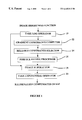
- the illumination compensation system of the present invention includes the following.
- An image brightness functions inputted to a take LOG operator where the logarithm of the image brightness function is taken.
- the gradient constraints are computed using a finite difference.
- the reliable constrains selector the reliable gradient constraints are selected based on a local uniformity test.
- a surface fitting processor a process is subsequently applied to estimate the logarithmic irradiance function.
- an image subtractor the logarithmic irradiance function is subtracted from the logarithmic image brightness function.
- a take exponential operator the exponential operation of the above subtracted image function is taken and the illumination compensated image is outputted from the system.
- FIG. 1 illustrates a flow chart of the present invention.
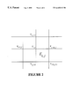
- FIG. 2 illustrates a square non-conforming finite element E i,j that the element basis function is a second-order polynomial with coefficients determined by its neighboring nodal variables.
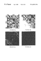
- FIG. 3 illustrates (a) a reference image, (b) an inspection image, (c) a difference image without illumination compensation, and (d) a difference image with the illumination compensation system applied before image subtraction.
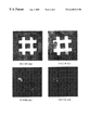
- FIG. 4 illustrates (a) a reference image, (b) an inspection image, (c) a difference image without illumination compensation, and (d) a difference image with the illumination compensation system applied before image subtraction.
- the image reference approach is very popular in industrial inspection due to its generality for different inspection tasks. Unfortunately, this approach is sensitive to illumination variations.
- the present invention provides an illumination compensation system for correcting smooth intensity variations due to illumination changes. By using the present invention as a pre-processing step in the image reference based inspection or localization, the image inspection or localization is made more robust against spatially smooth illumination changes.
- the flow chart of the illumination compensation system of the present invention is shown in FIG. 1 .
- the image brightness function is inputted to the take LOG operator 10 where the logarithm of the image brightness function is taken.
- gradient constraints computer 12 the gradient constraints are computed using finite difference.
- reliable constraints selector 14 reliable gradient constraints are selected based on a local uniformity test.
- surface fitting processor 16 a process is subsequently applied to estimate the logarithmic irradiance function.
- image subtractor 18 the logarithmic irradiance function is subtracted from the logarithmic image brightness function.
- take exponential operator 20 the exponential operation of the above subtracted image function is taken and the illumination compensated image is outputted from the system.
- the present invention is based on the assumption that the underlining image reflectance function is approximately a piecewise constant and that the image irradiance function is spatially smooth.
- reliable constraints selector 14 reliable gradient constraints on the smooth irradiance function are computed and selected from the image brightness function by using a local uniformity test.
- surface fitting processor 16 two surface fitting systems are presented to recover the smooth image irradiance function from the elected reliable gradient constraints found in gradient constraints computer 12 .
- One is a polynomial surface fitting system and the other is a spline surface fitting system.
- the spline surface fitting formulation leads to solving a large linear system, which is accomplished by an efficient preconditioned conjugate gradient system. Once the image irradiance function is estimated, the spatial intensity inhomogeneities can be easily compensated.
- the image brightness value b(x,y) at a location (x,y) is related to the product of the irradiance e(x,y) and image reflectance r(x,y) as follows:
- irradiance denotes the power per unit area of radiant energy falling on a surface
- reflectance is the percentage of the light reflected by the objects in the scene.
- the irradiance function directly relates to the illumination condition, and the reflectance function depends on the physical property of the objects. It is assumed that the irradiance function is spatially smooth in the image domain and the reflectance function is approximately a piecewise constant. The above assumption is valid for many industrial inspection environments.
- the irradiance function is estimated from the observed image data and the non-uniform irradiance component is removed from the image brightness function.
- logarithmic operations on both sides of equation (1) are calculated. This yields
- the partial derivatives of b′(x,y) appearing on the right-hand sides of equation (3) and (4) can be computed via finite difference method.
- the selection of the gradient constraints at the locations inside regions of uniform reflectance is facilitated by a local uniformity test that determines if the pixels in a local neighborhood belong to the same object with a uniform reflectance value. This local uniformity test is accomplished by checking the variance as well as the goodness of fit using a first-order polynomial.
- this function can be estimated by using surface fitting techniques.
- a polynomial surface fitting system and a spline surface fitting system for recovering the logarithmic irradiance function will be described below.
- the image reflectance function is the modified intensity function with the non-uniform illumination factor, i.e. irradiance function, removed from the image brightness. Therefore, it can be considered the illumination compensated function.
- the following will describe the two surface fitting systems, of surface fitting processor 16 , for recovering the smooth irradiance function from the selected gradient constraints.
- One is a polynomial surface fitting system and the other is a spline surface system.
- the former is more efficient than the latter, while the latter is more powerful in recovering different shapes of irradiance surface than the former.
- the irradiance function is assumed to be spatially smooth, it can be approximated by a low order polynomial function.
- the approximation of irradiance function using a second-order polynomial function can be written as
- This energy function can be minimized via solving the following linear system. ( 4 ⁇ ⁇ i ⁇ x i 2 2 ⁇ ⁇ i ⁇ x i ⁇ y i 0 2 ⁇ ⁇ x i i 0 2 ⁇ ⁇ i ⁇ x i ⁇ y i ⁇ i ⁇ ( x i 2 + y i 2 ) 2 ⁇ ⁇ i ⁇ x i ⁇ y i 2 ⁇ ⁇ i ⁇ y i ⁇ i ⁇ x i 0 2 ⁇ ⁇ i ⁇ x i ⁇ y i 4 ⁇ ⁇ i ⁇ y i 2 0 2 ⁇ ⁇ i ⁇ y i 2 ⁇ ⁇ x i i 2 ⁇ ⁇ y i i 0 n 0 0 ⁇ i ⁇ x i 2 ⁇ ⁇ i ⁇ y i 0 n ⁇
- illumination compensation system of the present invention is beneficial to achieve a robust visual inspection system working under different illumination conditions.
- ⁇ is the image domain
- ⁇ (x,y) is a constraint selection function that assigns value 1 in the smooth regions and value 0 in the high gradient regions
- p(x,y) and q(x,y) are the partial derivatives of b′(x,y) with respect to x and y respectively
- ⁇ is the regularization parameter controlling the degree of smoothness.
- the second integral corresponds to the thin-plate smoothness imposed on the function e′(x,y). This is described by D. Terzopoulos in “Multilevel Computational Processes For Visual Surface Reconstruction”, Computer Vision, Graphics, Image Processing, Vol. 24, pp.52-96, 1983; and by D.
- non-conforming finite element basis to represent the image irradiance function e′(x,y) is shown and the energy functional given in equation (11) is discretized.
- a nodal variable ⁇ i,j is assigned at each vertex of an element square as shown in FIG. 2 .
- a second-order polynomial function p i,j (x,y) is defined as follows
- Equation (12) the finite element function given in equation (12) is represented in a local x-y coordinate with the origin shifted to the nodal location of ⁇ i,j .
- the orientation constraint selection function ⁇ i,j is determined from the goodness of fitting the data b′(x,y) in the neighborhood of the nodal location (i,j) by a first-order polynomial. The orientation constraint at a nodal point is selected when the fitting error in the neighborhood of this point is less than a threshold.
- the fitting error can be further utilized to indicate a confidence measure for the orientation constraints selected at the locations in Z.
- c is a positive constant.
- the constant c is empirically set to 0.1.
- the energy function E(v), given in Eq. (14), is a convex and quadratic function of the vector v.
- the matrix A can be formed from the computational molecules.
- the logarithmic image irradiance function can be obtained from the finite element basis representation given in equation (13). The following section will present an adaptive preconditioned conjugate gradient system to solve this linear system efficiently.
- the matrix A is a singular matrix with rank-1 deficiency. Since the null space of the matrix A is the set of vectors with identical entries, the solution to this linear system can be obtained up to a constant elevation. This is due to the fact that the factorization of the image intensity function b(x,y) into a smooth image irradiance function e(x,y) and an approximately piecewise image reflectance function r(x,y) is not unique.
- the matrix A is sparse, it is not tightly banded. Its bandwidth is roughly O(m)or O(n). Iterative methods are better suited than direct methods for solving this type of linear systems, since direct methods require the formation of intermediate matrices which are not necessarily sparse. This is described by J. Stoer and R. Bulirsch in Introduction to Numerical Analysis , Springer-Verlag, Second Edition, 1993. More precisely, the matrix factorization schemes involved in the direct methods produce intermediate matrices that are triangular and whose bandwidths are no larger than the bandwidth of the original matrix. However, fill-in does occur within the band after the matrix factorization for the 2D and higher dimensional problems. This can cause the number of operations and the amount of storage too expensive for 2D and higher dimensional problems.
- the present invention uses an adaptive preconditioned conjugate gradient system to solve the large and sparse linear system.
- the conjugate gradient system can be used to solve the problem.
- a positive-definite preconditioner P is used to accelerate the convergence, it is known as the preconditioned conjugate gradient (PCG) system given as follows.
- the present invention uses an adaptive wavelet preconditioner to accelerate the convergence of the PCG system. This is described by S.-H. Lai and B. C. Vemuri in “Physically Based Adaptive Preconditioning For Early Vision”, IEEE Trans. Pattern Analysis Machine Intelligence, Vol. 19, No. 6, pp. 594-607, 1997.
- This adaptive preconditioner is constructed based on approximating the spectral characteristics of the matrix A.
- the matrix A consists of two components namely, one component matrix from the discretization of the orientation constraints and the other from the thin-plate smoothness.
- an approximate spectral function for the matrix A can be obtained.
- This spectral function is used to modulate the frequency characteristics of a chosen wavelet basis and these modulated values are then used in the construction of the preconditioner.
- the preconditioner is constructed in a wavelet basis and the motivation for using a wavelet basis as opposed to the Fourier basis is primarily computational.
- the computation for constructing the preconditioner can be achieved with O(N) operations in a wavelet basis unlike the O(N log N) computational complexity required for a Fourier basis, where N is the total number of discretization nodes.
- FIG. 3 depicts an example of visual inspection using the image subtraction approach.
- FIG. 3 ( a ) is the reference image
- FIG. 3 ( b ) is an inspection image of the same object under a different illumination condition.
- a pattern alignment system was first applied to align these two images and estimate the uniform illumination scaling and bias factors.
- the pattern alignment system is described in U.S. patent application Ser. No. 08/993,850 entitled “A Method For Localization Refinement Of Pattern Images” filed on Dec. 18, 1997, assigned to the same assignee as the present invention and hereby incorporated by reference. Then the difference between the inspection image and the warped image is shown in FIG. 3 ( c ).
- FIG. 3 ( d ) is the difference image for the illumination compensated inspection and reference images. This yields a nearly zero difference image.
- the spline-fitting based compensation system was applied. It is obvious that the present invention drastically improves the visual inspection result.
- FIG. 4 Another example is depicted in FIG. 4 .
- FIG. 4 ( a ) is the reference image and FIG. 4 ( b ) is a defected inspection image.
- the difference image for the aligned inspection and reference image is shown in FIG. 4 ( c ). It can be seen that there is some significant differences in the difference image in addition to the defect areas, which are due to the illumination variations between the two images. This problem is greatly improved by using the illumination compensation system of the present invention. As evident in FIG. 4 ( d ), the significant differences between the illumination compensated inspection and reference images are restricted in the defect areas.
- the present invention is an illumination compensation system that corrects smooth intensity variations due to illumination changes.
- the illumination compensation system is based on the assumption that the underlining image reflectance function is approximately a piecewise constant and the image irradiance function is spatially smooth.
- Reliable gradient constraints on the smooth irradiance function are computed and selected from the image brightness function by using a local uniformity test.
- the present invention includes an option of two surface fitting systems to recover the smooth image irradiance function from the selected reliable gradient constraints.
- One is a polynomial surface fitting system and the other is a spline surface fitting system.
- the spline surface fitting system leads to solving a large linear system, which is accomplished by an efficient preconditioned conjugate gradient system. Once the image irradiance function is estimated, the spatial intensity inhomogeneities can be easily compensated.
Abstract
Description


Claims (21)
Priority Applications (1)
| Application Number | Priority Date | Filing Date | Title |
|---|---|---|---|
| US09/235,997 US6445812B1 (en) | 1999-01-22 | 1999-01-22 | Illumination compensation system for industrial inspection |
Applications Claiming Priority (1)
| Application Number | Priority Date | Filing Date | Title |
|---|---|---|---|
| US09/235,997 US6445812B1 (en) | 1999-01-22 | 1999-01-22 | Illumination compensation system for industrial inspection |
Publications (1)
| Publication Number | Publication Date |
|---|---|
| US6445812B1 true US6445812B1 (en) | 2002-09-03 |
Family
ID=22887707
Family Applications (1)
| Application Number | Title | Priority Date | Filing Date |
|---|---|---|---|
| US09/235,997 Expired - Fee Related US6445812B1 (en) | 1999-01-22 | 1999-01-22 | Illumination compensation system for industrial inspection |
Country Status (1)
| Country | Link |
|---|---|
| US (1) | US6445812B1 (en) |
Cited By (13)
| Publication number | Priority date | Publication date | Assignee | Title |
|---|---|---|---|---|
| US20030007685A1 (en) * | 2001-04-26 | 2003-01-09 | Yao-Hong Tsai | Methods and system for illuminant-compensation |
| US6681037B1 (en) * | 1999-05-27 | 2004-01-20 | Cognex Corporation | Apparatus for locating features of an object using varied illumination |
| US6750971B2 (en) | 1999-12-08 | 2004-06-15 | X-Rite, Incorporated | Optical measurement device and related process |
| US6768812B1 (en) | 1999-05-27 | 2004-07-27 | Cognex Corporation | Method for locating features on an object using varied illumination |
| US6870949B2 (en) | 2003-02-26 | 2005-03-22 | Electro Scientific Industries | Coaxial narrow angle dark field lighting |
| US20050163397A1 (en) * | 2004-01-23 | 2005-07-28 | Electric Scientific Industries | Image subtraction of illumination artifacts |
| US20110150338A1 (en) * | 2009-12-18 | 2011-06-23 | Tandent Vision Science, Inc. | Method and system for generating intrinsic images using single reflectance technique |
| US8063908B1 (en) * | 2007-11-08 | 2011-11-22 | Nvidia Corporation | System, method, and computer program product for validating a graphics processor design |
| US8311358B2 (en) | 2010-05-11 | 2012-11-13 | Chung-Hua University | Method and system for image extraction and identification |
| US20160180148A1 (en) * | 2009-12-18 | 2016-06-23 | Tandent Vision Science, Inc. | Method and system for generating intrinsic images using a single reflectance technique |
| CN109211919A (en) * | 2018-09-03 | 2019-01-15 | 珠海格力智能装备有限公司 | Magnetic shoe collapses recognition methods and the device in missing plot domain |
| US10916005B2 (en) * | 2014-11-24 | 2021-02-09 | Kitov Systems Ltd | Automated inspection |
| US20220292665A1 (en) * | 2019-10-02 | 2022-09-15 | Konica Minolta, Inc. | Workpiece surface defect detection device and detection method, workpiece surface inspection system, and program |
Citations (4)
| Publication number | Priority date | Publication date | Assignee | Title |
|---|---|---|---|---|
| US4707119A (en) * | 1984-08-31 | 1987-11-17 | Fuji Photo Film Co., Ltd. | Photographic printer |
| US5546475A (en) * | 1994-04-29 | 1996-08-13 | International Business Machines Corporation | Produce recognition system |
| US5619587A (en) * | 1991-05-10 | 1997-04-08 | Aluminum Company Of America | System and method for contactlessly gauging the thickness of a contoured object, such as a vehicle wheel |
| US5774573A (en) * | 1984-12-20 | 1998-06-30 | Orbotech Ltd. | Automatic visual inspection system |
-
1999
- 1999-01-22 US US09/235,997 patent/US6445812B1/en not_active Expired - Fee Related
Patent Citations (4)
| Publication number | Priority date | Publication date | Assignee | Title |
|---|---|---|---|---|
| US4707119A (en) * | 1984-08-31 | 1987-11-17 | Fuji Photo Film Co., Ltd. | Photographic printer |
| US5774573A (en) * | 1984-12-20 | 1998-06-30 | Orbotech Ltd. | Automatic visual inspection system |
| US5619587A (en) * | 1991-05-10 | 1997-04-08 | Aluminum Company Of America | System and method for contactlessly gauging the thickness of a contoured object, such as a vehicle wheel |
| US5546475A (en) * | 1994-04-29 | 1996-08-13 | International Business Machines Corporation | Produce recognition system |
Cited By (21)
| Publication number | Priority date | Publication date | Assignee | Title |
|---|---|---|---|---|
| US6681037B1 (en) * | 1999-05-27 | 2004-01-20 | Cognex Corporation | Apparatus for locating features of an object using varied illumination |
| US6768812B1 (en) | 1999-05-27 | 2004-07-27 | Cognex Corporation | Method for locating features on an object using varied illumination |
| US6750971B2 (en) | 1999-12-08 | 2004-06-15 | X-Rite, Incorporated | Optical measurement device and related process |
| US20050122518A1 (en) * | 1999-12-08 | 2005-06-09 | Overbeck James L. | Optical measurement device and related process |
| US7020345B2 (en) * | 2001-04-26 | 2006-03-28 | Industrial Technology Research Institute | Methods and system for illuminant-compensation |
| US20030007685A1 (en) * | 2001-04-26 | 2003-01-09 | Yao-Hong Tsai | Methods and system for illuminant-compensation |
| US6870949B2 (en) | 2003-02-26 | 2005-03-22 | Electro Scientific Industries | Coaxial narrow angle dark field lighting |
| CN100347584C (en) * | 2003-02-26 | 2007-11-07 | 电科学工业公司 | Coaxial narrow angle dark field lighting |
| US20050163397A1 (en) * | 2004-01-23 | 2005-07-28 | Electric Scientific Industries | Image subtraction of illumination artifacts |
| US7599576B2 (en) | 2004-01-23 | 2009-10-06 | Electro Scientific Industries, Inc. | Image subtraction of illumination artifacts |
| US8063908B1 (en) * | 2007-11-08 | 2011-11-22 | Nvidia Corporation | System, method, and computer program product for validating a graphics processor design |
| US20110150338A1 (en) * | 2009-12-18 | 2011-06-23 | Tandent Vision Science, Inc. | Method and system for generating intrinsic images using single reflectance technique |
| US8385655B2 (en) * | 2009-12-18 | 2013-02-26 | Tandent Vision Science, Inc. | Method and system for generating intrinsic images using single reflectance technique |
| US20160180148A1 (en) * | 2009-12-18 | 2016-06-23 | Tandent Vision Science, Inc. | Method and system for generating intrinsic images using a single reflectance technique |
| US9396411B2 (en) | 2009-12-18 | 2016-07-19 | Tandent Vision Science, Inc | Method and system for generating intrinsic images using a single reflectance technique |
| US9754155B2 (en) * | 2009-12-18 | 2017-09-05 | Tandent Vision Science, Inc. | Method and system for generating intrinsic images using a single reflectance technique |
| US8311358B2 (en) | 2010-05-11 | 2012-11-13 | Chung-Hua University | Method and system for image extraction and identification |
| US10916005B2 (en) * | 2014-11-24 | 2021-02-09 | Kitov Systems Ltd | Automated inspection |
| CN109211919A (en) * | 2018-09-03 | 2019-01-15 | 珠海格力智能装备有限公司 | Magnetic shoe collapses recognition methods and the device in missing plot domain |
| CN109211919B (en) * | 2018-09-03 | 2021-04-30 | 珠海格力智能装备有限公司 | Method and device for identifying magnetic tile defect area |
| US20220292665A1 (en) * | 2019-10-02 | 2022-09-15 | Konica Minolta, Inc. | Workpiece surface defect detection device and detection method, workpiece surface inspection system, and program |
Similar Documents
| Publication | Publication Date | Title |
|---|---|---|
| US6353678B1 (en) | Method and apparatus for detecting independent motion in three-dimensional scenes | |
| US6445812B1 (en) | Illumination compensation system for industrial inspection | |
| US7526140B2 (en) | Model-based localization and measurement of miniature surface mount components | |
| EP1329850B1 (en) | Apparatus, program and method for detecting both stationary objects and moving objects in an image | |
| US5271064A (en) | Apparatus and method for smoothing regions and enhancing edges in gray scale images | |
| US6937235B2 (en) | Three-dimensional object surface shape modeling apparatus, method and program | |
| EP0778543A2 (en) | A gradient based method for providing values for unknown pixels in a digital image | |
| US8411995B2 (en) | Deconvolution-based structured light system with geometrically plausible regularization | |
| US7098998B2 (en) | Depth measuring method and depth measuring apparatus | |
| US6330353B1 (en) | Method of localization refinement of pattern images using optical flow constraints | |
| US11080892B2 (en) | Computer-implemented methods and system for localizing an object | |
| US6917721B2 (en) | Method and apparatus for sub-pixel edge detection | |
| Trinder et al. | Semi-automatic feature extraction by snakes | |
| US20020126915A1 (en) | Method for image alignment under non-uniform illumination variations | |
| US6208138B1 (en) | Bias field estimation for intensity inhomogeneity correction in MR images | |
| US9008363B1 (en) | System and method for computing optical flow | |
| JP2024507089A (en) | Image correspondence analysis device and its analysis method | |
| US20050114103A1 (en) | System and method for sequential kernel density approximation through mode propagation | |
| US7103229B2 (en) | Image simplification using a robust reconstruction filter | |
| KR101222009B1 (en) | System and method for lens distortion compensation of camera based on projector and epipolar geometry | |
| US10692269B2 (en) | Method and device for image processing | |
| Chung et al. | Pose estimation considering an uncertainty model of stereo vision for in-water ship hull inspection | |
| CN114820418A (en) | Image exception handling method and device, terminal equipment and readable storage medium | |
| CN115239569A (en) | Image vignetting removal method, panoramic image generation method and related equipment | |
| US6611562B1 (en) | Image processing device and image processing method, and computer-readable recorded medium |
Legal Events
| Date | Code | Title | Description |
|---|---|---|---|
| AS | Assignment |
Owner name: SIEMENS CORPORATE RESEARCH, INC., NEW JERSEY Free format text: ASSIGNMENT OF ASSIGNORS INTEREST;ASSIGNORS:LAI, SHANG-HONG;FANG, MING;REEL/FRAME:009718/0654 Effective date: 19990121 |
|
| FPAY | Fee payment |
Year of fee payment: 4 |
|
| FEPP | Fee payment procedure |
Free format text: PAYOR NUMBER ASSIGNED (ORIGINAL EVENT CODE: ASPN); ENTITY STATUS OF PATENT OWNER: LARGE ENTITY |
|
| FPAY | Fee payment |
Year of fee payment: 8 |
|
| AS | Assignment |
Owner name: SIEMENS CORPORATION,NEW JERSEY Free format text: MERGER;ASSIGNOR:SIEMENS CORPORATE RESEARCH, INC.;REEL/FRAME:024185/0042 Effective date: 20090902 |
|
| REMI | Maintenance fee reminder mailed | ||
| LAPS | Lapse for failure to pay maintenance fees | ||
| STCH | Information on status: patent discontinuation |
Free format text: PATENT EXPIRED DUE TO NONPAYMENT OF MAINTENANCE FEES UNDER 37 CFR 1.362 |
|
| FP | Lapsed due to failure to pay maintenance fee |
Effective date: 20140903 |