US6437733B1 - Method of processing multipath navigation signals in a receiver having a plurality of antennas - Google Patents

Method of processing multipath navigation signals in a receiver having a plurality of antennas Download PDF

Info

Publication number
US6437733B1
US6437733B1 US09/659,579 US65957900A US6437733B1 US 6437733 B1 US6437733 B1 US 6437733B1 US 65957900 A US65957900 A US 65957900A US 6437733 B1 US6437733 B1 US 6437733B1
Authority
US
United States
Prior art keywords
signals
delays
paths
navigation
signals corresponding
Prior art date
Legal status (The legal status is an assumption and is not a legal conclusion. Google has not performed a legal analysis and makes no representation as to the accuracy of the status listed.)
Expired - Fee Related
Application number
US09/659,579
Inventor
Jesus Selva Vera
Current Assignee (The listed assignees may be inaccurate. Google has not performed a legal analysis and makes no representation or warranty as to the accuracy of the list.)
Agence Spatiale Europeenne
Original Assignee
Agence Spatiale Europeenne
Priority date (The priority date is an assumption and is not a legal conclusion. Google has not performed a legal analysis and makes no representation as to the accuracy of the date listed.)
Filing date
Publication date
Application filed by Agence Spatiale Europeenne filed Critical Agence Spatiale Europeenne
Assigned to AGENCE SPATIALE EUROPEENNE reassignment AGENCE SPATIALE EUROPEENNE ASSIGNMENT OF ASSIGNORS INTEREST (SEE DOCUMENT FOR DETAILS). Assignors: SELVA VERA, JESUS
Application granted granted Critical
Publication of US6437733B1 publication Critical patent/US6437733B1/en
Anticipated expiration legal-status Critical
Expired - Fee Related legal-status Critical Current

Links

Images

Classifications

    • HELECTRICITY
    • H04ELECTRIC COMMUNICATION TECHNIQUE
    • H04BTRANSMISSION
    • H04B7/00Radio transmission systems, i.e. using radiation field
    • H04B7/02Diversity systems; Multi-antenna system, i.e. transmission or reception using multiple antennas
    • H04B7/04Diversity systems; Multi-antenna system, i.e. transmission or reception using multiple antennas using two or more spaced independent antennas
    • H04B7/08Diversity systems; Multi-antenna system, i.e. transmission or reception using multiple antennas using two or more spaced independent antennas at the receiving station
    • H04B7/0837Diversity systems; Multi-antenna system, i.e. transmission or reception using multiple antennas using two or more spaced independent antennas at the receiving station using pre-detection combining
    • H04B7/0842Weighted combining
    • H04B7/0845Weighted combining per branch equalization, e.g. by an FIR-filter or RAKE receiver per antenna branch
    • GPHYSICS
    • G01MEASURING; TESTING
    • G01SRADIO DIRECTION-FINDING; RADIO NAVIGATION; DETERMINING DISTANCE OR VELOCITY BY USE OF RADIO WAVES; LOCATING OR PRESENCE-DETECTING BY USE OF THE REFLECTION OR RERADIATION OF RADIO WAVES; ANALOGOUS ARRANGEMENTS USING OTHER WAVES
    • G01S19/00Satellite radio beacon positioning systems; Determining position, velocity or attitude using signals transmitted by such systems
    • G01S19/01Satellite radio beacon positioning systems transmitting time-stamped messages, e.g. GPS [Global Positioning System], GLONASS [Global Orbiting Navigation Satellite System] or GALILEO
    • G01S19/13Receivers
    • G01S19/22Multipath-related issues
    • GPHYSICS
    • G01MEASURING; TESTING
    • G01SRADIO DIRECTION-FINDING; RADIO NAVIGATION; DETERMINING DISTANCE OR VELOCITY BY USE OF RADIO WAVES; LOCATING OR PRESENCE-DETECTING BY USE OF THE REFLECTION OR RERADIATION OF RADIO WAVES; ANALOGOUS ARRANGEMENTS USING OTHER WAVES
    • G01S19/00Satellite radio beacon positioning systems; Determining position, velocity or attitude using signals transmitted by such systems
    • G01S19/01Satellite radio beacon positioning systems transmitting time-stamped messages, e.g. GPS [Global Positioning System], GLONASS [Global Orbiting Navigation Satellite System] or GALILEO
    • G01S19/13Receivers
    • G01S19/35Constructional details or hardware or software details of the signal processing chain
    • G01S19/36Constructional details or hardware or software details of the signal processing chain relating to the receiver frond end
    • HELECTRICITY
    • H04ELECTRIC COMMUNICATION TECHNIQUE
    • H04BTRANSMISSION
    • H04B1/00Details of transmission systems, not covered by a single one of groups H04B3/00 - H04B13/00; Details of transmission systems not characterised by the medium used for transmission
    • H04B1/69Spread spectrum techniques
    • H04B1/707Spread spectrum techniques using direct sequence modulation
    • H04B1/7097Interference-related aspects
    • H04B1/711Interference-related aspects the interference being multi-path interference
    • H04B1/7115Constructive combining of multi-path signals, i.e. RAKE receivers
    • H04B1/7117Selection, re-selection, allocation or re-allocation of paths to fingers, e.g. timing offset control of allocated fingers

Definitions

  • the subject of the present invention is a multipath navigation signal processing method adapted to a receiver having a plurality of receiving antennas.
  • a navigation receiver of the direct-sequence-code-division multiple-access and pseudo-range estimation type the reflections which introduce a delay of less than one bit of a pseudorandom noise sequence (or “chip”) are liable to introduce a large time error.
  • a receiver having a plurality of receiving antennas the attenuation of the effects of these multiple paths depends on the number of antennas in the receiver since each antenna generates a linear combination between the direct signal and the signals corresponding to multiple paths, and this information can be used by an attenuation algorithm.
  • channel will refer to the signal coming from one antenna and a receiver will be called single-channel or multichannel depending on whether it has one or more antennas.
  • the principle of maximum probability is used to estimate the time, and in particular the DDLLs (Digital Delay Lock Loops) constitute an approximation of this principle for a signal and a channel in white noise.
  • the use of the principle of maximum probability results, in the case of the aforementioned reflections, in a nonlinear equation and the signal processing is correspondingly complicated thereby.
  • MEDLLs Multipath Estimating Delay Lock Loops
  • MEDLLs Multipath Estimating Delay Lock Loops
  • they require at least twice as many correlators as the aforementioned DDLLs and to solve the nonlinear equations requires an appreciably longer time than the advance/delay correlation of a DDLL.
  • the MEDLL technique is described in particular in the article by Brian Townsend et al., entitled “L 1 Carrier Phase Multipath Error Reduction Using MEDLL Technology”, published in 1995 in “Proceedings of the Institute of Navigation GPS”, pages 1539-1533, as well as in the article by Richard Van Nee et al., entitled “The Multipath Estimating Delay Lock Loop: Approaching Theoretical Accuracy Limits”, published in 1994 in the journal IEEE, pages 246-251.
  • a DDLL loop correlates the input signal with a locally generated replica. The loop then chooses, among all the possible correlations, as one for each delay, that which is closest to the input signal. The distance between two correlations is conventionally measured using a vector, which results in the solution of a linear minimization problem.
  • the present invention is provided for achieving a similar formulation in the case of a multichannel receiver.
  • the invention thus relates to a method of processing navigation signals for a satellite navigation system using a receiver, characterized in that the receiver has a plurality of antennas generating signals representative of the reception of signals corresponding to direct paths and to reflected paths and in that it carries out a search for the delays of the signals corresponding to direct paths and to reflected paths by comparing them with reference signals corresponding to known delays.
  • One particularly advantageous embodiment of the invention relies on the notion that the input signals of the various channels cover the same vector subspace as the direct signals and the signals coming from reflections.
  • each antenna signal so as to filter it, by a filter matched to the waveform of the navigation signals of said navigation system and to its spectrum spreading code, and to take an average over the peaks of the filtered signals;
  • Said decomposition into singular values is preferably carried out for samples located around a correlation peak and in which most of the energy of the signal is concentrated. It may employ detection of a discontinuity in the singular values in order to estimate the rank p of the subspace S of the signal.
  • the method may be characterized in that said one-dimensional search is carried out in an estimated delay timeslot in which signals corresponding to a direct path and signals corresponding to reflected paths can be found.
  • Said one-dimensional search may comprise:
  • FIG. 1 illustrates the preprocessing
  • FIG. 2 illustrates the decomposition into singular values, applied after preprocessing in a multichannel receiver MCR
  • FIG. 3 illustrates the one-dimensional search
  • FIG. 4 illustrates a preferred preprocessing mode
  • FIG. 5 shows the output of the matched filter F i for the ith channel
  • FIG. 6 illustrates the mode generation
  • the technique mentioned above which employs a maximum probability estimator, firstly filters the input signal by means of a filter matched to the code and then compares the correlations obtained with local replicas using a nonlinear equation.
  • the unknowns in this equation are the complex signal amplitudes and the delays, which means that a practical implementation, such as MEDLL, can take several minutes and therefore can be used only for a differential GPS system.
  • the signals coming from N antennas A 1 , A 2 , A i . . . A N are all firstly, for the ith antenna A i , amplified by a low-noise amplifier AMP i , filtered by a band-pass filter BPF i and baseband transposed in a mixer M i , one input of which receives for this purpose a local carrier LC.
  • a preprocessing module 1 i they are digitized by an analog-digital converter ADC i and then filtered by a filter F i matched to the waveform of the pulses and to the spectrum spreading code.
  • Such a filter is a finite impulse response (FIR) filter whose impulse response is obtained by sampling a window of the navigation signal, using more than one sample per pseudorandom signal bit (or chip) so that the waveform of the samples is reflected in the samples. Finally, it may be averaged in a step PA i for calculating the peak value average in order to deliver a preprocessed signal.
  • FIR finite impulse response
  • the spreading-corrected peak signals which are output by the filter F i are processed by taking samples located about the estimated correlation peak and each of these samples is averaged for several correlation peaks so as to increase the signal/noise ratio.
  • the preprocessed signal relates only to a small number of samples located around the correlation peak, given that the energy of the signal is mainly in these samples.
  • the method of the invention then employs, in a module 2 (see FIG. 2 ), an estimation of the subspace S of the signal by decomposition into singular values of vectors z 1 , Z 2 , . . . , Z nch formed from the samples of the correlation peaks of each of the nch antennas A 1 , A 2 , . . . , A nch-1 , A nch .
  • the method employs a one-dimensional search in a delay timeslot within which the direct signal and the signals coming from a reflection can lie (see FIG. 3 ).
  • This timeslot may be obtained by a rough estimation employing a known technique such as the use of a conventional DDLL loop by means of a DW circuit.
  • the reference preprocessing circuit 1 i locally generates mode vectors z i corresponding to noise-free incident signals having known given delays.
  • the delay searches are carried out by seeking, by means of the module 2 , those which are the closest mode vectors of the signal subspace S. The delays then value the delays corresponding to these closest mode vectors.
  • the one-dimensional search may be carried out, for example, by calculating, in the delay timeslot, the inverse of the distance between the signal subspace S and each of the modes which are locally generated, the delays of the direct signals and of the signals that have undergone reflections then being able to be estimated in a module 4 by seeking the delay values for which the “inverse of the distance” function is a maximum.
  • the method according to the invention results, for a signal/noise ratio of a ⁇ 20 dB C/A code (taken before the filter F i ) and for an integration time of only one second (i.e. approximately 1000 codes), in an error of the order of one hundredth of a bit of a pseudorandom noise sequence (1/100 of a chip), which is very much less than the result obtained with a DDLL loop ( ⁇ 5.6 hundredths of a bit).
  • n m number of modes
  • n ch number of channels
  • n L dimension of the space, that is to say the length of the vectors
  • ⁇ a ⁇ largest integer less than or equal to a ;
  • V 1 , V 2 , . . . ] matrix formed by the column vectors V 1 , V 2 . . . ;
  • rank [.] rank of a matrix or of a subspace
  • tr(.) sums of the diagonal elements of a matrix.
  • n wbp (t) white band-pass noise
  • n m number of multipath signals.
  • n w [n] sampled noise
  • R rs,i (n, ⁇ ) and R s ( ⁇ 1 , ⁇ 2 ) are given by the following correlation formulae:
  • the estimation is equivalent to making n m reference autocorrelations correspond to ns channel correlations, with complex amplitudes and different delays.
  • the unknowns are only the delays, since the amplitudes can be obtained from ( 7 ) and replaced in ( 8 ). This results in nonlinear equations.
  • Equations (7) and (8) are the MEDLL equations [see the work by Richard Van Nee “Multi-transmitter Interference in Special Spectrum Communication and Navigation System”, Delft University Press, The Netherlands, (1995)].
  • an estimation of the subspace is made from the same correlations. Consequently, in both cases, the signals of the various channels must undergo a preprocessing in order to obtain the channel correlations.
  • the signal r i (t) of the ith channel is sampled at intervals T s in a sampling module ADC i and passes through the filter F i corresponding to the reference signal (a code period of s( ⁇ )).
  • the output z i [n] of the filter is given by:
  • h[n] denotes the response of the matched filter.
  • the output signals z i [n] of the matched filter F i are illustrated in FIG. 5 . Given that the level of the signals is high enough only for the samples located near the correlation peaks, only these are observed. It is possible for example, as indicated above, to determine approximately the position of the peaks and to choose a time reference t iL so that:
  • T denotes the time interval around the correlation peaks.
  • the circuit keeps only the samples located in the slot:
  • This estimation is also a function of the reference autocorrelation which can also be obtained by means of the circuit in FIG. 4 (without the module VG) by using s(t ⁇ ) as input signal (see FIG. 6) and by dispensing with the averaging operation, since there is no noise.
  • the outputs thus obtained, called modes (or mode vectors), are:
  • Equation (8) the data processing for making an estimation using the principle of maximum probability according to Equation (8) is very complicated.
  • the present method allows the solution of this problem to be considerably simplified by using a different concept which consists firstly in estimating the subspace in which most of the power of the signal is concentrated and then in seeking the closest modes (or mode vectors) by means of a one-dimensional search.
  • the channel vectors Z 1 , Z 2 , . . . zn nch are linear combinations of the mode vectors m 1 , m 2 , . . . mn m .
  • n L dimension of the space
  • the mode vectors may be obtained from the values of ⁇ for which m( ⁇ ) is orthogonal to the subspace N, i.e.:
  • the above method is not suitable given that the mode vectors lie in fact only within a subspace of the channel space. It is therefore necessary to find, from C, the subspace CS around which most of the energy is concentrated and then to apply the above parametric search method.
  • This condition may be reformulated in the following manner:
  • This Equation (23) represents the square of the Frobenius norm applied to the matrix z—H p .
  • Equation 24 The problem of how to minimize this norm is solved by applying a decomposition into singular values (Equation 24) which allows z to be expressed in the form:
  • the matrix H p may be expressed in the form:
  • the rank for which this occurs may be evaluated by detecting a discontinuity in the rest of the singular values so that ⁇ 2 1 , ⁇ 2 2 , . . . , and ⁇ 2 p are of the same order of magnitude and that ⁇ 2 p+1 , ⁇ 2 p+2 , . . . , and ⁇ 2 min(n l n ch ) are very small.
  • the parametric mode search is carried out using Equation (22) by calculating the value ⁇ for which:
  • the parametric search detects the closest mode vectors.
  • the separation between the signal subspace ⁇ U 1 > and the noise subspace ⁇ U 2 > is detected by a discontinuity in the sequence of the singular values.
  • This discontinuity can be detected by starting with the smallest singular value and by comparing the successive increments of these singular values with their mean increment and a discontinuity is regarded as being detected if its relative value is greater than a given threshold.
  • This threshold may be chosen so as to correspond to a temporal error within the ⁇ 25 to ⁇ 20 dB range, this being a typical value for a C/A code.
  • Such a criterion is particularly useful if, for a given mode, the number of channels is greater than the number of samples. In practice, it will be noted that it is preferable to overestimate (rather than underestimate) the number of singular values.
  • the one-dimensional search is carried out in the manner explained above, thereby making it possible to determine the desired delays for the signals corresponding to a direct path and for those corresponding to paths having undergone reflections.

Abstract

A method of processing navigation signals for a satellite navigation system using a receiver. The receiver is provided with a plurality of antennas generating antenna signals corresponding to the reception of signals corresponding to direct paths and to reflected paths. The method advantageously uses: a) a preprocessing of each antenna signal so as to filter it by a matched filter and to take an average over the peaks of the filtered signals; b) a decomposition into singular values in order to make an estimation of a signal subspace from the filtered and averaged signals representative of the correlation peaks; and c) a search for the delays of the signals corresponding to direct paths and to reflected paths.

Description

BACKGROUND OF THE INVENTION Field of the Invention
The subject of the present invention is a multipath navigation signal processing method adapted to a receiver having a plurality of receiving antennas.
In a navigation receiver of the direct-sequence-code-division multiple-access and pseudo-range estimation type, the reflections which introduce a delay of less than one bit of a pseudorandom noise sequence (or “chip”) are liable to introduce a large time error. In the case envisioned here, a receiver having a plurality of receiving antennas, the attenuation of the effects of these multiple paths depends on the number of antennas in the receiver since each antenna generates a linear combination between the direct signal and the signals corresponding to multiple paths, and this information can be used by an attenuation algorithm.
BACKGROUND
Conventionally, the term “channel” will refer to the signal coming from one antenna and a receiver will be called single-channel or multichannel depending on whether it has one or more antennas.
From a theoretical standpoint, the principle of maximum probability is used to estimate the time, and in particular the DDLLs (Digital Delay Lock Loops) constitute an approximation of this principle for a signal and a channel in white noise. The use of the principle of maximum probability results, in the case of the aforementioned reflections, in a nonlinear equation and the signal processing is correspondingly complicated thereby. MEDLLs (Multipath Estimating Delay Lock Loops) are a good example of this: they require at least twice as many correlators as the aforementioned DDLLs and to solve the nonlinear equations requires an appreciably longer time than the advance/delay correlation of a DDLL.
SUMMARY OF THE INVENTION
The MEDLL technique is described in particular in the article by Brian Townsend et al., entitled “L1 Carrier Phase Multipath Error Reduction Using MEDLL Technology”, published in 1995 in “Proceedings of the Institute of Navigation GPS”, pages 1539-1533, as well as in the article by Richard Van Nee et al., entitled “The Multipath Estimating Delay Lock Loop: Approaching Theoretical Accuracy Limits”, published in 1994 in the journal IEEE, pages 246-251.
A technique for attenuating the multipath effects using the MEDLL technique is also described in the article by G. El Sayed et al., entitled “Design of GPS Receiver Code and Carrier Tracking Loops for Multipath Mitigation”, published in 1998 in Proceedings of the 11th International Technical Meeting of the Institute of Navigation, Nashville, pages 1041 to 1052. This technique is applied only to a single signal and is therefore suitable only for a single-channel receiver.
In general, a DDLL loop correlates the input signal with a locally generated replica. The loop then chooses, among all the possible correlations, as one for each delay, that which is closest to the input signal. The distance between two correlations is conventionally measured using a vector, which results in the solution of a linear minimization problem.
The present invention is provided for achieving a similar formulation in the case of a multichannel receiver.
The invention thus relates to a method of processing navigation signals for a satellite navigation system using a receiver, characterized in that the receiver has a plurality of antennas generating signals representative of the reception of signals corresponding to direct paths and to reflected paths and in that it carries out a search for the delays of the signals corresponding to direct paths and to reflected paths by comparing them with reference signals corresponding to known delays.
One particularly advantageous embodiment of the invention relies on the notion that the input signals of the various channels cover the same vector subspace as the direct signals and the signals coming from reflections.
It is therefore possible to estimate this subspace and then to use the distance between the subspace and the local correlations in order to formulate the minimization problem.
The method is therefore characterized in that it comprises:
a) a preprocessing of each antenna signal so as to filter it, by a filter matched to the waveform of the navigation signals of said navigation system and to its spectrum spreading code, and to take an average over the peaks of the filtered signals;
b) a decomposition into singular values in order to make an estimation of a vector signal subspace S from the filtered and averaged signals representative of the correlation peaks;
c) a one-dimensional search for the delays of the signals corresponding to direct paths and to reflected paths, by seeking the delays corresponding to minima in the distance between locally generated mode vectors corresponding to reference signals, the delays of which are known, and the vectors of the subspace S.
Said decomposition into singular values is preferably carried out for samples located around a correlation peak and in which most of the energy of the signal is concentrated. It may employ detection of a discontinuity in the singular values in order to estimate the rank p of the subspace S of the signal.
The method may be characterized in that said one-dimensional search is carried out in an estimated delay timeslot in which signals corresponding to a direct path and signals corresponding to reflected paths can be found.
Said one-dimensional search may comprise:
c1) a calculation in said delay timeslot of the inverse of the distance between the vectors of the subspace S and the locally generated mode vectors;
c2) an estimation of the delays of the signals corresponding to a direct path and of the signals corresponding to reflected paths by choosing the delays corresponding to the mode vectors for which the values of said inverses of the distance are a maximum.
BRIEF DESCRIPTION OF THE DRAWINGS
The invention will be more clearly understood on reading the description which follows, given by way of example and in conjunction with the drawings in which:
FIG. 1 illustrates the preprocessing;
FIG. 2 illustrates the decomposition into singular values, applied after preprocessing in a multichannel receiver MCR;
FIG. 3 illustrates the one-dimensional search;
FIG. 4 illustrates a preferred preprocessing mode;
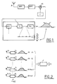
FIG. 5 shows the output of the matched filter Fi for the ith channel; and
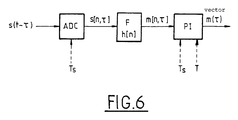
FIG. 6 illustrates the mode generation.
DETAILED DESCRIPTION OF THE INVENTION
The technique mentioned above, which employs a maximum probability estimator, firstly filters the input signal by means of a filter matched to the code and then compares the correlations obtained with local replicas using a nonlinear equation. The unknowns in this equation are the complex signal amplitudes and the delays, which means that a practical implementation, such as MEDLL, can take several minutes and therefore can be used only for a differential GPS system.
The concept proposed within the context of the present invention makes it possible to replace the nonlinear minimization step and this can be applied to an arbitrary geometry of the array, provided that the number of signals incident on the array is less than the number of elements making up the array.
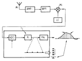
According to the present invention (FIG. 1), the signals coming from N antennas A1, A2, Ai . . . AN are all firstly, for the ith antenna Ai, amplified by a low-noise amplifier AMPi, filtered by a band-pass filter BPFi and baseband transposed in a mixer Mi, one input of which receives for this purpose a local carrier LC. Next, in a preprocessing module 1 i, they are digitized by an analog-digital converter ADCi and then filtered by a filter Fi matched to the waveform of the pulses and to the spectrum spreading code. Such a filter is a finite impulse response (FIR) filter whose impulse response is obtained by sampling a window of the navigation signal, using more than one sample per pseudorandom signal bit (or chip) so that the waveform of the samples is reflected in the samples. Finally, it may be averaged in a step PAi for calculating the peak value average in order to deliver a preprocessed signal. According to this technique, the spreading-corrected peak signals which are output by the filter Fi are processed by taking samples located about the estimated correlation peak and each of these samples is averaged for several correlation peaks so as to increase the signal/noise ratio.
The preprocessed signal relates only to a small number of samples located around the correlation peak, given that the energy of the signal is mainly in these samples.
As will be explained in greater detail in the rest of the description, the method of the invention then employs, in a module 2 (see FIG. 2), an estimation of the subspace S of the signal by decomposition into singular values of vectors z1, Z2, . . . , Znch formed from the samples of the correlation peaks of each of the nch antennas A1, A2, . . . , Anch-1, Anch.
Once the subspace S of the signal has been estimated, the method employs a one-dimensional search in a delay timeslot within which the direct signal and the signals coming from a reflection can lie (see FIG. 3). This timeslot may be obtained by a rough estimation employing a known technique such as the use of a conventional DDLL loop by means of a DW circuit. The reference preprocessing circuit 1 i locally generates mode vectors zi corresponding to noise-free incident signals having known given delays. The delay searches are carried out by seeking, by means of the module 2, those which are the closest mode vectors of the signal subspace S. The delays then value the delays corresponding to these closest mode vectors. The one-dimensional search may be carried out, for example, by calculating, in the delay timeslot, the inverse of the distance between the signal subspace S and each of the modes which are locally generated, the delays of the direct signals and of the signals that have undergone reflections then being able to be estimated in a module 4 by seeking the delay values for which the “inverse of the distance” function is a maximum.
The method according to the invention results, for a signal/noise ratio of a −20 dB C/A code (taken before the filter Fi) and for an integration time of only one second (i.e. approximately 1000 codes), in an error of the order of one hundredth of a bit of a pseudorandom noise sequence (1/100 of a chip), which is very much less than the result obtained with a DDLL loop (≅5.6 hundredths of a bit).
The reasoning is based on a C/A code having shaped pulses (β=0.5).
The following notation is used:
nm=number of modes;
nch=number of channels;
nL=dimension of the space, that is to say the length of the vectors;
(.)T=transpose of a matrix;
(.)H=conjugate and transpose of a matrix;
└a┘=largest integer less than or equal to a;
a mod b=remainder of the division of a by b;
<V1, V2, . . . >=V1, V2, . . . space;
[V1, V2, . . . ]=matrix formed by the column vectors V1, V2 . . . ;
rank [.]=rank of a matrix or of a subspace;
diag(.)=diagonal of a matrix;
min(.,.)=minimum; and
tr(.)=sums of the diagonal elements of a matrix.
The model of a band-pass signal for the ith receiving channel is: r bpi ( t ) k = 1 n m α ik s ( t - τ k ) cos ( ω t + θ ik ) + n wbp ( t ) , i = 1 , , n ch ( 1 )
Figure US06437733-20020820-M00001
where
s(t)=C/A code with shaped pulses;
nwbp(t)=white band-pass noise;
αik=actual amplitude;
θik=multipath phases.
The low-pass equivalent of rbpi(t) is: r i ( t ) 1 2 k = 1 n m α ik j θ ik s ( t - τ κ ) + n w ( t ) = k = 1 n m a ik s ( t - τ κ ) + n w ( t ) , i = 1 , , n ch ( 2 )
Figure US06437733-20020820-M00002
where:
nw(t)=white noise
aik≡{fraction (1/2)}αikeik=multipath complex coefficients  (3)
τk=multipath delays
nm=number of multipath signals.
After sampling for a period Ts, N samples are available for each channel. Therefore: r i [ n ] k = 1 n m a ik s [ n , τ κ ] + n w [ n ] , i = 1 , , n ch , ( 4 )
Figure US06437733-20020820-M00003
where:
s[n,τ]=s(nT s−τ)=reference signal  (5)
sampled with a delay τ;
nw[n]=sampled noise.
The values of aik and of τk, when N samples are available per channel, may be estimated using the maximum probability function, namely: L - i = 1 n ch m = 0 N - 1 r i [ n - ( N - 1 ) + m ] - k = 1 n m a ik s [ m , τ k ] 2 ( 6 )
Figure US06437733-20020820-M00004
The estimations of the amplitude ai1k1 and of the delay τR1 satisfy the following equations: R rs , i 1 [ n , τ k 1 ] ~ k = 1 n m a i 1 k R s ( τ κ , τ k 1 ) = 0 , i 1 = 1 , , n ch , k 1 = 1 , , n m , and ( 7 ) [ τ ^ k 1 , , τ ^ n m ] = arg min [ τ k 1 , , τ n m ] { i = 1 n cn Re { a ik 1 ( R rsj [ n , τ κ 1 ] - k = 1 , k = k 1 n m a ik R s ( τ κ , τ k 1 ) ) } } ( 8 )
Figure US06437733-20020820-M00005
in which equation Rrs,i (n, τ) and Rs 1, τ2) are given by the following correlation formulae: R rsj [ n , τ ] = m = 0 N - 1 r i [ n - ( N - t ) ÷ m ] s [ m τ ] ( 9 )
Figure US06437733-20020820-M00006
(channel reference correlation) R s ( τ 1 , τ 2 ) R s ( τ 2 - τ 1 ) = m = 0 N - 1 s [ m , τ 1 ] s [ m , τ 2 ] ( 10 )
Figure US06437733-20020820-M00007
(reference autocorrelation).
The estimation is equivalent to making nm reference autocorrelations correspond to ns channel correlations, with complex amplitudes and different delays. The unknowns are only the delays, since the amplitudes can be obtained from (7) and replaced in (8). This results in nonlinear equations.
If nch=1, Equations (7) and (8) are the MEDLL equations [see the work by Richard Van Nee “Multi-transmitter Interference in Special Spectrum Communication and Navigation System”, Delft University Press, The Netherlands, (1995)].
According to the invention, instead of making an estimation which makes the channel correlations correspond to reference correlations, resulting in nonlinear equations, an estimation of the subspace is made from the same correlations. Consequently, in both cases, the signals of the various channels must undergo a preprocessing in order to obtain the channel correlations.
In particular, it is the few samples located near the correlation peaks which are of interest (see the circuit in FIG. 4).
In this circuit, the signal ri(t) of the ith channel is sampled at intervals Ts in a sampling module ADCi and passes through the filter Fi corresponding to the reference signal (a code period of s(−τ)). The output zi[n] of the filter is given by:
zi[n]=ri*h[n]  (11)
where h[n] denotes the response of the matched filter.
The output signals zi[n] of the matched filter Fi are illustrated in FIG. 5. Given that the level of the signals is high enough only for the samples located near the correlation peaks, only these are observed. It is possible for example, as indicated above, to determine approximately the position of the peaks and to choose a time reference tiL so that:
tiL=NTs−T/2(L=1, . . . ,npi, where npi denotes the number of correlations peaks available for the ith channel).
T denotes the time interval around the correlation peaks. The circuit keeps only the samples located in the slot:
[NTS−T, NTs]  (12)
Since the duration of the interval T is known, the samples generated by the module PI and located in the [tiL−T/2,tiL+T/2] slot constitute a vector ziL:
z iL =[z i [LN−└T/T s ┘],z i [LN−└T/T s┘+1], . . . |z i [LN]] T  (13)
These are samples around the Lth correlation peak.
Since the signal-to-noise ratio of these samples may prove not to be high enough, it is advantageous in this case to take an average over npi correlation peaks in a module VG. In this way, what are called the channel vectors zi (with i between 1 and nch), also called Ci (FIG. 2), are obtained. Thus: z i = 1 n pi L = 1 n pi z iL ( 14 )
Figure US06437733-20020820-M00008
The channel vector is equivalent to the channel reference correlation of the maximum probability estimator according to Equation 9, given that: ( r i = h ) [ n ] = k = - + h [ k ] r i [ n - k ] = k = 0 N - 1 s [ N - k · 0 ] r i [ n - k ] ( 15 )
Figure US06437733-20020820-M00009
At the instant n=N—p, with p<<N, the output of the matched filter has the value: ( r i = h ) [ N - p ] = k = 0 N - 1 s [ N - k · 0 ] r i [ N - p - k ] = k = - p N - 1 - p s [ N - k - p · 0 ] r i [ N - k ] R rs [ N , ρ T s ] ( 16 )
Figure US06437733-20020820-M00010
This estimation is also a function of the reference autocorrelation which can also be obtained by means of the circuit in FIG. 4 (without the module VG) by using s(t−τ) as input signal (see FIG. 6) and by dispensing with the averaging operation, since there is no noise. The outputs thus obtained, called modes (or mode vectors), are:
m[n,τ]=(s[.,τ]*h)[n]  (17)
(reference correlation);
m(τ)=[m[└−T/2┘+1,τ]m[└−T/2┘+2,τ], . . . m[└T/2|τ]]T(modes)  (18)
The modes m(τ) are equivalent to the reference autocorrelation (maximum probability) according to Equation (10) since: ( s [ τ ] * h ) [ n ] = k = - + h [ k ] s [ n - k , τ ] = k = 0 N - 1 s [ N - k · 0 ] s [ n - k , τ ] ( 19 )
Figure US06437733-20020820-M00011
At the instant n=N−p, with p<<N, the output of the filter F is: ( s [ τ ] * h ) [ N - p ] = k = 0 N - 1 s [ N - k , τ ] s [ N - p - k , τ ] = k = 0 N - 1 s [ N - k , τ ] s [ N + k , τ + ρ T s ] R s ( ρ T s ) ( 20 )
Figure US06437733-20020820-M00012
As indicated above, the data processing for making an estimation using the principle of maximum probability according to Equation (8) is very complicated. The present method allows the solution of this problem to be considerably simplified by using a different concept which consists firstly in estimating the subspace in which most of the power of the signal is concentrated and then in seeking the closest modes (or mode vectors) by means of a one-dimensional search.
In the absence of noise, the channel vectors Z1, Z2, . . . znnch are linear combinations of the mode vectors m1, m2 , . . . mnm.
The channel vectors and the mode vectors lie within the same subspace S=C, where:
S=<m1,m2, . . . mnm>(signal subspace)
C=<z1,z2, . . . znch. (channel subspace).
Since the mode vectors are the values of a function at a parameter mi=m(τi), where i=1 . . . nm, it is possible to determine the mode vectors intersecting the variety m(τ) with the channel subspace.
The following notation is used:
nL=dimension of the space
N=S=<n1, n2, . . . , nnL−nm>, noise subspace or subspace orthogonal to S;
m(τ), mode vectors as a function of the parameter τ
mi=m(τi) modes, i=1 . . . ,nm.
The channel vectors z1, z2, . . . , znch are linear combinations of the modes, namely: z i = k = 1 n m a ik m k , i = η , , n ch ( 21 )
Figure US06437733-20020820-M00013
aik being constants.
The mode vectors may be obtained from the values of τ for which m(τ) is orthogonal to the subspace N, i.e.:
n H k .m(τ)=0, k=1, . . . n L −n m  (22)
When noise is present, the above method is not suitable given that the mode vectors lie in fact only within a subspace of the channel space. It is therefore necessary to find, from C, the subspace CS around which most of the energy is concentrated and then to apply the above parametric search method.
Let the matrix z=[z1,z2, . . . , znch]. The rank p of the matrix Hp for which the sum of the squares of the elements of z—Hp is a minimum is sought.
This condition may be reformulated in the following manner:
e 2 =tr((z−H p)H(z−H p))  (23)
This Equation (23) represents the square of the Frobenius norm applied to the matrix z—Hp.
The reader should refer to the work by Louis L. Scharf entitled “Statistical Signal Processing, Detection, Estimation and Time Series Analysis”, page 45, published in 1991 by Addison-Wesley Publishing Company Inc.
The problem of how to minimize this norm is solved by applying a decomposition into singular values (Equation 24) which allows z to be expressed in the form:
z=UΣVH  (24)
U, being an orthogonal matrix with dimensions nL=nLn, is a diagonal matrix with dimensions nL=nchand V is an orthogonal matrix with dimensions nch=nch. The diagonal elements of the matrix, which are called singular values, are positive or zero. They are classed by decreasing values:
diag(Σ)=[λ2 12 2, . . . ,λ2 min(n L n ch) ]  (25)
The matrix Hp may be expressed in the form:
Hρ=UΣρVH  (26)
U and V being given by (24).
Substituting the result of Equations (24) and (26) into Equation (23) and taking into account the fact that UUH=I and VVH=I gives:
θ2 =tr((z−H p)H(z−H p))=tr(V(Σ−ΣH p)U H U(Σ−Σp)V H)
tr(V(Σ−ΣH p)(Σ−Σp)V H)=tr((Σ−ΣH p)(Σ−Σp))  ( 27)
Since the matrix Hp is of rank p, the error is minimal when Σp is diagonal and cancels out the elements of its diagonal, the order of which is greater than pi, namely:
diag(Σp)=[λ1 2λ2 2, . . . ,λ2 p, 0, 0, . . . ]  (28)
The rank for which this occurs may be evaluated by detecting a discontinuity in the rest of the singular values so that λ2 1, λ2 2, . . . , and λ2 p are of the same order of magnitude and that λ2 p+1, λ2 p+2, . . . , and λ2 min(n l n ch ) are very small.
This works only if the signal-to-noise ratio is better than 0 dB since:
λ2 i2 si+σ 2 n,1≦i≦p
λ2 i2 n , p+1≦i≦min(l n $)  (29)
[lacuna] denoting the singular values of the signal and [lacuna] the variance of the noise (see the aforementioned work by Louis L. Scharf, pages 499-500).
The method may therefore be summarized in the following manner:
Decomposition of z into singular values:
z=UΣVH;
Detection of a discontinuity in the singular values and calculation therefrom of an estimated value of the rank p of the subspace;
The rank p is given by z=UΣpVH where Σpcontains only p diagonal elements.
If we write U=[U1 U2], where U1 contains the p first columns and U2 the remaining nL-ρcolumns, then <U1> is the approximate subspace of rank ρ (signal subspace) and <U2> is its orthogonal complement (noise subspace).
The parametric mode search is carried out using Equation (22) by calculating the value ρ for which:
m(τ)HU2=0  (30).
Given that the norm of Equation 30 is small, τ may be estimated by searching for the maxima of the inverse of the square of the norm, namely: P ( τ ) = 1 m ( τ ) H U 2 2 ( delay spectrum ) . ( 31 )
Figure US06437733-20020820-M00014
The singular values will allow a distinction to be made between the signal subspace and the noise subspace. Once the subspace has been estimated, the parametric search detects the closest mode vectors.
The separation between the signal subspace <U1> and the noise subspace <U2> is detected by a discontinuity in the sequence of the singular values. This discontinuity can be detected by starting with the smallest singular value and by comparing the successive increments of these singular values with their mean increment and a discontinuity is regarded as being detected if its relative value is greater than a given threshold. This threshold may be chosen so as to correspond to a temporal error within the −25 to −20 dB range, this being a typical value for a C/A code. Such a criterion is particularly useful if, for a given mode, the number of channels is greater than the number of samples. In practice, it will be noted that it is preferable to overestimate (rather than underestimate) the number of singular values.
Once the subspace has been determined, the one-dimensional search is carried out in the manner explained above, thereby making it possible to determine the desired delays for the signals corresponding to a direct path and for those corresponding to paths having undergone reflections.

Claims (8)

What is claimed is:
1. Method of processing navigation signals for a satellite navigation system using a receiver, wherein the receiver has a plurality of antennas generating antenna signals representative of received navigation signals corresponding to direct paths and to reflected paths, and the receiver carries out a search for the delays of the navigation signals corresponding to direct paths and to reflected paths by comparing the antenna signals with a vector signal subspace obtained from pre-processed antenna signals.
2. Method according to claim 1, wherein the method comprises:
a) a preprocessing of each antenna signal so as to filter it, by a filter matched to the waveform of the navigation signals of said navigation system and to its spectrum spreading code, and to take an average over the peaks of the filtered signals;
b) a decomposition into singular values in order to make an estimation of said vector signal subspace from the filtered and averaged signals representative of the correlation peaks;
c) a one-dimensional search for said delays of the navigation signals corresponding to direct paths and to reflected paths, by seeking the delays corresponding to minima in the distance between locally generated mode vectors corresponding to said reference signals, the delays of which are known, and said vector signal subspace.
3. Method according to claim 2, wherein said decomposition into singular values is carried out for samples located around a correlation peak and around which most of the energy of the antenna signal is concentrated.
4. Method according to claim 3, wherein the decomposition into singular values employs detection of a discontinuity in the singular values in order to estimate the rank p of the subspace S of the antenna signal.
5. Method according to any one of the preceding claims, wherein said one-dimensional search is carried out in an estimated delay timeslot in which navigation signals corresponding to a direct path and navigation signals corresponding to reflected paths can be found.
6. Method according to claim 5, wherein said one-dimensional search comprises:
c1) a calculation in said delay timeslot of the inverse of the distance between the vectors of the vector signal subspace and the locally generated mode vectors;
c2) an estimation of the delays of the navigation signals corresponding to a direct path and of the navigation signals corresponding to reflected paths by choosing the delays corresponding to the mode vectors for which the values of said inverses of the distance are a maximum.
7. Method of processing navigation signals for a satellite navigation system using a receiver, wherein the receiver has a plurality of antennas generating antenna signals representative of received navigation signals corresponding to direct paths and to reflected paths and in that it carries out a search for the delays of the navigation signals corresponding to direct paths and to reflected paths by comparing the antenna signals with reference signals corresponding to known delays, wherein the method comprises the following steps:
a) a preprocessing of each antenna signal so as to filter it, by a filter matched to the waveform of the navigation signals of said navigation system and to its spectrum spreading code, and to take an average over the peaks of the filtered signals;
b) a decomposition into singular values in order to make an estimation of a vector signal subspace from the filtered and averaged signals representative of the correlation peaks;
c) a one-dimensional search for said delays of the navigation signals corresponding to direct paths and to reflected paths, by seeking the delays corresponding to minima in the distance between locally generated mode vectors corresponding to said reference signals, the delays of which are known, and said vector signal subspace.
8. Method of processing navigation signals for a satellite navigation system using a receiver, wherein the receiver has a plurality of antennas generating antenna signals representative of the reception of navigation signals corresponding to direct paths and to reflected paths and in that it carries out a search for the delays of the signals corresponding to direct paths and to reflected paths by comparing the antenna signals with reference signals corresponding to known delays, and
wherein said one-dimensional search is carried out in an estimated delay timeslot in which navigation signals corresponding to a direct path and navigation signals corresponding to reflected paths can be found.
US09/659,579 1999-09-17 2000-09-11 Method of processing multipath navigation signals in a receiver having a plurality of antennas Expired - Fee Related US6437733B1 (en)

Applications Claiming Priority (2)

Application Number Priority Date Filing Date Title
FR9911662 1999-09-17
FR9911662A FR2798794B1 (en) 1999-09-17 1999-09-17 METHOD FOR PROCESSING MULTI-PATH NAVIGATION SIGNALS IN A RECEIVER HAVING A PLURALITY OF ANTENNAS

Publications (1)

Publication Number Publication Date
US6437733B1 true US6437733B1 (en) 2002-08-20

Family

ID=9549976

Family Applications (1)

Application Number Title Priority Date Filing Date
US09/659,579 Expired - Fee Related US6437733B1 (en) 1999-09-17 2000-09-11 Method of processing multipath navigation signals in a receiver having a plurality of antennas

Country Status (5)

Country Link
US (1) US6437733B1 (en)
EP (1) EP1085341B1 (en)
DE (1) DE60035555T2 (en)
ES (1) ES2290003T3 (en)
FR (1) FR2798794B1 (en)

Cited By (6)

* Cited by examiner, † Cited by third party
Publication number Priority date Publication date Assignee Title
US20040054528A1 (en) * 2002-05-01 2004-03-18 Tetsuya Hoya Noise removing system and noise removing method
US20070104256A1 (en) * 2005-11-09 2007-05-10 Seiko Epson Corporation Positioning apparatus, control method of positioning apparatus, control program for positioning apparatus, and computer readable recording medium for storing control program for positioning apparatus
WO2012025306A1 (en) 2010-08-27 2012-03-01 Thales Space-time multi-antenna and multi-correlator device for rejecting multi-paths in navigation systems
DE102012206912A1 (en) 2011-05-06 2012-11-08 Deutsches Zentrum für Luft- und Raumfahrt e.V. Method for determining operational time of signal transmitted from transmitter, such as satellite or base station to receiver, involves calculating mathematical derivative of transmitted signal according to operational time
CN102833016A (en) * 2012-08-20 2012-12-19 电子科技大学 Determination method in allusion to homogenous signal time difference under multipath environment
CN112994774A (en) * 2021-02-02 2021-06-18 展讯通信(上海)有限公司 Method and device for determining direct path in satellite communication

Families Citing this family (2)

* Cited by examiner, † Cited by third party
Publication number Priority date Publication date Assignee Title
CN102253360B (en) * 2011-04-14 2013-04-03 上海大学 Method capable of automatically regulating threshold value for estimating number of cyclostationary signal sources
DE102016225548A1 (en) 2015-12-22 2017-06-22 Deutsches Zentrum für Luft- und Raumfahrt e.V. Method for multipath suppression utilizing polarization for satellite signals

Citations (3)

* Cited by examiner, † Cited by third party
Publication number Priority date Publication date Assignee Title
US5359521A (en) * 1992-12-01 1994-10-25 Caterpillar Inc. Method and apparatus for determining vehicle position using a satellite based navigation system
WO1997040398A2 (en) 1996-04-25 1997-10-30 Sirf Technology, Inc. Spread spectrum receiver with multi-bit correlator
WO1998005128A1 (en) 1996-07-29 1998-02-05 Qualcomm Incorporated Coherent signal processing for cdma communication system

Patent Citations (3)

* Cited by examiner, † Cited by third party
Publication number Priority date Publication date Assignee Title
US5359521A (en) * 1992-12-01 1994-10-25 Caterpillar Inc. Method and apparatus for determining vehicle position using a satellite based navigation system
WO1997040398A2 (en) 1996-04-25 1997-10-30 Sirf Technology, Inc. Spread spectrum receiver with multi-bit correlator
WO1998005128A1 (en) 1996-07-29 1998-02-05 Qualcomm Incorporated Coherent signal processing for cdma communication system

Cited By (9)

* Cited by examiner, † Cited by third party
Publication number Priority date Publication date Assignee Title
US20040054528A1 (en) * 2002-05-01 2004-03-18 Tetsuya Hoya Noise removing system and noise removing method
US20070104256A1 (en) * 2005-11-09 2007-05-10 Seiko Epson Corporation Positioning apparatus, control method of positioning apparatus, control program for positioning apparatus, and computer readable recording medium for storing control program for positioning apparatus
US7830306B2 (en) * 2005-11-09 2010-11-09 Seiko Epson Corporation Positioning apparatus, control method of positioning apparatus, control program for positioning apparatus, and computer readable recording medium for storing control program for positioning apparatus
WO2012025306A1 (en) 2010-08-27 2012-03-01 Thales Space-time multi-antenna and multi-correlator device for rejecting multi-paths in navigation systems
DE102012206912A1 (en) 2011-05-06 2012-11-08 Deutsches Zentrum für Luft- und Raumfahrt e.V. Method for determining operational time of signal transmitted from transmitter, such as satellite or base station to receiver, involves calculating mathematical derivative of transmitted signal according to operational time
DE102012206912B4 (en) * 2011-05-06 2017-04-06 Deutsches Zentrum für Luft- und Raumfahrt e.V. Method for determining the transit time of signals between a transmitter and a receiver
CN102833016A (en) * 2012-08-20 2012-12-19 电子科技大学 Determination method in allusion to homogenous signal time difference under multipath environment
CN102833016B (en) * 2012-08-20 2014-11-05 电子科技大学 Determination method in allusion to homogenous signal time difference under multipath environment
CN112994774A (en) * 2021-02-02 2021-06-18 展讯通信(上海)有限公司 Method and device for determining direct path in satellite communication

Also Published As

Publication number Publication date
FR2798794B1 (en) 2001-11-16
FR2798794A1 (en) 2001-03-23
EP1085341A1 (en) 2001-03-21
DE60035555T2 (en) 2008-06-19
ES2290003T3 (en) 2008-02-16
EP1085341B1 (en) 2007-07-18
DE60035555D1 (en) 2007-08-30

Similar Documents

Publication Publication Date Title
EP0925514B1 (en) Receiver with improved multipath signal rejection
US7042930B2 (en) Spread spectrum bit boundary correlation search acquisition system
US5764686A (en) Enhanced time of arrival method
EP1253434B1 (en) Method for estimating a direction of arrival
US5918161A (en) Method and apparatus for reducing multipath signal error using deconvolution
US20080211715A1 (en) Global positioning system using broadband noise reduction
US7257153B2 (en) Method of synchronizing a receiver, and a receiver
US20040052305A1 (en) Construction of an interference matrix for a coded signal processing engine
Vidal et al. High resolution time-of-arrival detection for wireless positioning systems
US6437733B1 (en) Method of processing multipath navigation signals in a receiver having a plurality of antennas
Vera Efficient multipath mitigation in navigation systems
US7421011B2 (en) Performing an acquisition in a receiver
US7242731B2 (en) Method for synchronizing a receiver, a system, and an electronic device
US7876807B2 (en) Asymmetry technique for multipath mitigation in pseudorandom noise ranging receiver
KR100981458B1 (en) Method and apparatus for signal receipt and acquisition
Enneking et al. Exploiting WSSUS multipath for GNSS ranging
EP1255121B1 (en) A method for reducing multipath interferences errors in a navigation receiver
Seco-Granados et al. Multipath and Interference Errors Reduction in GNSS by joint pseudorange measurement and array beamforming
Lyusin et al. Fast acquisition by matched filter technique for GPS/GLONASS receivers
US7253769B2 (en) Method for the elimination in a receiver of incident beams resulting from multipaths, and device for implementation
US6765951B2 (en) Method for estimating the channel impulse response of a mobile radio channel
US8050309B2 (en) Multipath discriminator module for a navigation system
Selva Subspace methods applied to multipath mitigation in a navigation receiver
AU720886B2 (en) Receiver with improved multipath signal rejection
Li et al. An Adaptive Signal Search Algorithm in GPS Receiver

Legal Events

Date Code Title Description
AS Assignment

Owner name: AGENCE SPATIALE EUROPEENNE, FRANCE

Free format text: ASSIGNMENT OF ASSIGNORS INTEREST;ASSIGNOR:SELVA VERA, JESUS;REEL/FRAME:011255/0634

Effective date: 20000918

FEPP Fee payment procedure

Free format text: PAYOR NUMBER ASSIGNED (ORIGINAL EVENT CODE: ASPN); ENTITY STATUS OF PATENT OWNER: LARGE ENTITY

FPAY Fee payment

Year of fee payment: 4

FPAY Fee payment

Year of fee payment: 8

REMI Maintenance fee reminder mailed
LAPS Lapse for failure to pay maintenance fees
STCH Information on status: patent discontinuation

Free format text: PATENT EXPIRED DUE TO NONPAYMENT OF MAINTENANCE FEES UNDER 37 CFR 1.362

FP Lapsed due to failure to pay maintenance fee

Effective date: 20140820