US6436357B1 - Instrument bracket for use with a sterilizable tray - Google Patents
Instrument bracket for use with a sterilizable tray Download PDFInfo
- Publication number
- US6436357B1 US6436357B1 US09/403,399 US40339999A US6436357B1 US 6436357 B1 US6436357 B1 US 6436357B1 US 40339999 A US40339999 A US 40339999A US 6436357 B1 US6436357 B1 US 6436357B1
- Authority
- US
- United States
- Prior art keywords
- tray
- metal strip
- stud
- skeleton
- attached
- Prior art date
- Legal status (The legal status is an assumption and is not a legal conclusion. Google has not performed a legal analysis and makes no representation as to the accuracy of the status listed.)
- Expired - Lifetime
Links
Images

Classifications
-
- A—HUMAN NECESSITIES
- A61—MEDICAL OR VETERINARY SCIENCE; HYGIENE
- A61L—METHODS OR APPARATUS FOR STERILISING MATERIALS OR OBJECTS IN GENERAL; DISINFECTION, STERILISATION OR DEODORISATION OF AIR; CHEMICAL ASPECTS OF BANDAGES, DRESSINGS, ABSORBENT PADS OR SURGICAL ARTICLES; MATERIALS FOR BANDAGES, DRESSINGS, ABSORBENT PADS OR SURGICAL ARTICLES
- A61L2/00—Methods or apparatus for disinfecting or sterilising materials or objects other than foodstuffs or contact lenses; Accessories therefor
- A61L2/26—Accessories or devices or components used for biocidal treatment
-
- A—HUMAN NECESSITIES
- A61—MEDICAL OR VETERINARY SCIENCE; HYGIENE
- A61B—DIAGNOSIS; SURGERY; IDENTIFICATION
- A61B50/00—Containers, covers, furniture or holders specially adapted for surgical or diagnostic appliances or instruments, e.g. sterile covers
- A61B50/30—Containers specially adapted for packaging, protecting, dispensing, collecting or disposing of surgical or diagnostic appliances or instruments
- A61B50/33—Trays
-
- A—HUMAN NECESSITIES
- A61—MEDICAL OR VETERINARY SCIENCE; HYGIENE
- A61L—METHODS OR APPARATUS FOR STERILISING MATERIALS OR OBJECTS IN GENERAL; DISINFECTION, STERILISATION OR DEODORISATION OF AIR; CHEMICAL ASPECTS OF BANDAGES, DRESSINGS, ABSORBENT PADS OR SURGICAL ARTICLES; MATERIALS FOR BANDAGES, DRESSINGS, ABSORBENT PADS OR SURGICAL ARTICLES
- A61L2202/00—Aspects relating to methods or apparatus for disinfecting or sterilising materials or objects
- A61L2202/20—Targets to be treated
- A61L2202/24—Medical instruments, e.g. endoscopes, catheters, sharps
Definitions
- the invention comprises a bracket for supporting medical instruments in a sterilizable tray in which the bracket body is formed primarily from resilient silicone and is strengthened by a relatively rigid spring tempered metal interior skeleton backbone.
- Instrument supporting brackets can take several different forms. Perhaps the most common form is a custom tray which includes custom made brackets laid out according to the specific request of the customer. An outline of the instrument to be supported is frequently printed on the bottom surface of the tray so that accurate instrument positioning is achieved. It is also common practice to place an English language legend, such as “Russian Tissue Forceps” adjacent to the outline of the desired instrument.
- the custom made brackets which generally have an irregular shape, are then permanently attached to the tray with rivets. While such trays have advantages, they have several disadvantages too. First of all, they are expensive and time consuming to produce because each tray has to be individualized for each specific customer's request. Second, brackets are not removable and, therefore, there is no flexibility in the layout of the tray. Instrument holding trays, such as described are sold under the trademark MEDITRAY® by Case Medical, Inc., 65 Railroad Avenue, Ridgefield, N.J. 07657.
- brackets Another technique for attaching prior art brackets to a sterilizable tray is to have the brackets slide into a keyway that is provided for on the tray itself.
- instrument holding brackets which comprise stainless steel or aluminum bodies covered with a thin coat of nylon.
- the brackets typically have an L-shaped cross section.
- a pair of studs is attached to the bottom of the L-shaped bracket with nylon serving as the adhesive.
- the stainless steel or aluminum brackets just described can then be placed selectively or randomly on a tray having a plurality of regularly spaced perforations therein.
- bracket that will: withstand high temperatures; provide secure support for heavy. instruments, yet light support for delicate instrumentation; provide for complete surrounding by steam; provide for the ability to grab and securely hold heavy and delicate instruments; provide flexibility and strong support at the same time; and, also, provide for the ability to place brackets at a wide variety of locations in order to accommodate a wide spectrum of instruments.
- the invention comprises a bracket for supporting medical instruments in a sterilizable tray in which the bracket body is formed primarily from resilient silicone and is strengthened by a relatively rigid metal interior skeleton backbone.
- the resilient silicone bracket body includes a plurality of medical instrument receiving indentations or valleys separated by intervening peaks. Resilient ribs formed in the instrument receiving indentations gently support the medical instruments and optimally allow sterilizing steam to be exposed to the maximum surface area of the instrument.
- the spring tempered stainless steel skeleton backbone is encapsulated by the silicone body.
- the skeleton also includes peaks and valleys that mimic and align with the peaks and valleys of the silicone body and provide additional strength thereto.
- Threaded studs are mechanically attached to the skeleton backbone.
- Each stud includes a slotted head which attaches to the bottom edge of the stainless steel skeleton backbone, a widened, ring-like midsection, and a threaded end that is distal from the slotted end of the stud.
- the slotted end and most of the round midsection of the stud are also encapsulated in the silicone.
- the bracket is preferably attached to the tray by placing the threaded portions of the studs through the perforations in the tray and attaching them thereto with lock nuts.
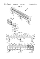
- FIG. 1 is a perspective view of the preferred embodiment of the sterilizable instrument bracket.
- FIG. 2 is a perspective view of the preferred embodiment of the invention illustrated in FIG. 1 shown in the process of being placed into a sterilizable tray and locked with respect thereto with lock nuts.
- FIG. 3 is a partial, perspective cross sectional view of the bracket illustrated in FIG. 1 showing the manner in which the slotted head of the studs are attached to the relatively rigid spring tempered skeleton backbone.
- FIG. 4 is a front, exploded view illustrating the manner in which the attachment studs are connected to the skeleton backbone.
- FIG. 5 is a partial, front cross sectional view of the fully assembled bracket.
- the preferred embodiment of the invention 10 is illustrated in a perspective view in FIG. 1 .
- the three major structural components of the preferred embodiment 10 are a resilient silicone body 12 , a skeleton backbone 14 encapsulated by the silicone body 12 and a plurality of threaded studs 16 partially encapsulated by the silicone body 12 .
- Bracket 10 is preferably attached to a sterilizable tray 18 such as illustrated in FIG. 2 .
- Tray 18 includes a plurality of regularly spaced perforations or apertures 20 for receiving the threaded sections 50 of studs 16 of bracket 10 .
- the threaded section or end 50 of studs 16 pass through the perforations 20 and are locked with respect thereto by lock nuts 52 which threadably attach to the threaded portion 50 on the portion of stud 16 opposite from the silicone body 12 .
- lock nuts 52 which threadably attach to the threaded portion 50 on the portion of stud 16 opposite from the silicone body 12 .
- Alternate methods could also be employed to attach studs 16 to tray 18 .
- the threaded sections 50 of the studs 16 could be smooth or threaded and a push on clip could be used instead of lock nuts 52 to secure the bracket 10 to the apertures 20 in tray 18 .
- a plurality of different medical instruments 22 are supported by brackets 10 as shown in FIG. 2 .
- Threaded studs 16 are located at intervals identical to the spacing between perforations 20 in tray 18 so that the brackets 10 may be placed in any arrangement for supporting medical instruments 22 . Therefore, it is easy to rearrange the brackets to accommodate a wide variety of different medical instruments 22 which may vary substantially in size, weight and shape.
- silicone body 12 its related relatively rigid spring tempered skeleton backbone 14 , and threaded support studs 16 will be more fully appreciated by referring to FIGS. 3-5.
- Medical instruments 22 are received in indentations or valleys 24 in the resilient silicone body 12 .
- the medical receiving indentations are separated by resilient peaks 26 .
- Ribs 28 located at regular intervals inside of the instrument receiving indentations 24 provide gentle yet turn support for the medical instruments 22 . More importantly, ribs 28 permit sterilizing steam to circulate in between so as to further assist in the killing of biohazardous germs and materials. There is a small gap between adjacent peaks 26 and the valleys 24 so as to further hold and secure an instrument 22 in the bracket 10 .
- the profile of the relatively rigid spring tempered stainless steel skeleton backbone 14 generally mimics the profile of the peaks 26 and valleys 24 of the resilient silicone body 12 .
- Skeleton backbone 14 therefore, includes valleys 30 separated by peaks 32 .
- Each skeleton backbone 14 also includes a top edge 40 which incorporates peaks 32 and valleys 30 , a bottom edge 42 which is attached to studs 16 , and a pair of side ends 34 .
- Flow through apertures 36 are located along the length of skeleton backbone 14 .
- a pair of flow through holes or apertures 38 oriented perpendicularly to flow through apertures 36 , are located in the side ends 34 of skeleton backbone 14 .
- Each stud 16 includes a head 44 , a ring shaped midsection 48 in the middle thereof, and a threaded end or section 50 distal from head 44 .
- a skeleton receiving slot 46 is located in stud head 44 , The slot 46 in stud head 44 is slightly smaller than the width of the skeleton backbone 14 so that it mechanically locks onto the bottom edge 42 of the skeleton backbone 14 . For additional security it may be desirable to weld the slotted head 44 to the bottom edge 42 of the skeleton backbone 14 .
- the ring shaped midsection 44 of stud 16 supports the bottom edge 42 of the skeleton backbone 14 .
- the bracket 10 is constructed in the following 35 manner.
- Three studs 16 are shown in FIGS. 1-5 but two studs 16 or four or more studs 16 could also be used according to the demands of the use. Studs 16 are preferably placed at regular intervals identical to the spacing between perforations 20 in tray 18 as previously described. Stud heads 44 are then mechanically attached to the bottom edge 42 of skeleton backbone 14 either by crimping or by welding, or both.
- Second, the skeleton backbone 14 with studs 16 attached is then placed into a mold in which silicone is injected to form resilient body 12 .
- the silicone completely encapsulates the skeleton backbone 14 . Flow through apertures 36 and 38 in skeleton backbone 14 further assist in mechanically anchoring the silicone body 12 to the skeleton backbone 14 . As previously described, the silicone also encapsulates the head 44 and most of the midsection 48 of stud 16 . The exposed portion of the midsection 48 of stud 16 also serves as a stop for the bracket 10 when it is placed in position on tray 18 .
- the resulting molded silicone bracket 10 includes sculpted indents 54 in the sides of the silicone bracket body 12 . Sculpted indents 54 help to conserve weight and space.
- the invention described has several significant, nonobvious advantages over the prior art.
- Presently existing prior art brackets do not allow for optimal sterilization as they tend to be bulky and grip a large surface area of the instrument 22 .
- Fifth, the spring tempered metal skeleton 14 permits the bracket 10 to adjust slightly so that the threaded portion 50 of the studs 16 can align with perforations 20 in the tray 18 even if there isn't perfect spacing.
Abstract
Description
Claims (11)
Priority Applications (1)
| Application Number | Priority Date | Filing Date | Title |
|---|---|---|---|
| US09/403,399 US6436357B1 (en) | 1997-04-22 | 1997-04-22 | Instrument bracket for use with a sterilizable tray |
Applications Claiming Priority (2)
| Application Number | Priority Date | Filing Date | Title |
|---|---|---|---|
| US09/403,399 US6436357B1 (en) | 1997-04-22 | 1997-04-22 | Instrument bracket for use with a sterilizable tray |
| PCT/US1997/006650 WO1998047544A1 (en) | 1997-04-22 | 1997-04-22 | Instrument bracket for use with a sterilizable tray |
Publications (1)
| Publication Number | Publication Date |
|---|---|
| US6436357B1 true US6436357B1 (en) | 2002-08-20 |
Family
ID=23595623
Family Applications (1)
| Application Number | Title | Priority Date | Filing Date |
|---|---|---|---|
| US09/403,399 Expired - Lifetime US6436357B1 (en) | 1997-04-22 | 1997-04-22 | Instrument bracket for use with a sterilizable tray |
Country Status (1)
| Country | Link |
|---|---|
| US (1) | US6436357B1 (en) |
Cited By (27)
| Publication number | Priority date | Publication date | Assignee | Title |
|---|---|---|---|---|
| US20020136679A1 (en) * | 2000-02-23 | 2002-09-26 | Frieze Allan S. | Filtered gas plasma sterilization container with improved circulation |
| US20030118491A1 (en) * | 1998-08-26 | 2003-06-26 | Frieze Marcia A. | Filtered gas plasma sterilization container with improved circulation |
| US20050158222A1 (en) * | 2004-01-15 | 2005-07-21 | William I. Summers | Method of manufacture and apparatus for sterilization cassettes and baskets |
| US20050163686A1 (en) * | 2004-01-15 | 2005-07-28 | William I. Summers | Sterilization case with matrix base |
| US20050249651A1 (en) * | 2004-05-07 | 2005-11-10 | Riley Edward D | Surgical instrument bracket assembly |
| FR2886856A1 (en) * | 2005-06-14 | 2006-12-15 | Hygien Or Sarl | Sterilization tray for e.g. surgical instrument, has blank formed by molding synthetic material and including transversal ribs with cuttings arranged on top of ribs, where cuttings form communication between upper and lower surfaces of tray |
| US20060283773A1 (en) * | 2005-05-16 | 2006-12-21 | Ho Thi Q | Retention latch for packaging apparatus |
| US20070009408A1 (en) * | 2005-07-08 | 2007-01-11 | Riley Edward D | Medical instrument retainer assembly |
| US20070134142A1 (en) * | 2005-12-12 | 2007-06-14 | Riley Edward D | Medical instrument retainer assembly and method of making the retainer |
| US20070144926A1 (en) * | 2005-05-24 | 2007-06-28 | Bettenhausen Todd E | Modular container for the storage, organization, protection, sterilization and delivery of medical instruments and implants |
| US20070215507A1 (en) * | 2006-03-20 | 2007-09-20 | Glenn William S | Modular surgical tray and delivery system |
| US20080121563A1 (en) * | 2006-06-06 | 2008-05-29 | Dennis Polvere | Product display systems |
| US20080149512A1 (en) * | 2006-12-22 | 2008-06-26 | Dane Gary T | Medical instrument bracket assembly |
| US20100040935A1 (en) * | 2008-08-12 | 2010-02-18 | General Electric Company | Fuel cell element electrode |
| US20100176016A1 (en) * | 2009-01-14 | 2010-07-15 | Mack Molding Company | Instrument tray assembly and brackets for inserting into an instrument tray |
| JP2013153967A (en) * | 2012-01-30 | 2013-08-15 | Fuji Flex Co Ltd | Tray for sterilization case |
| EP2671530A1 (en) | 2012-06-04 | 2013-12-11 | DePuy (Ireland) | Surgical instrument tray |
| US20150129524A1 (en) * | 2013-11-12 | 2015-05-14 | Symmetry Medical Manufacturing Inc. | Tray and Bracket System and Related Methods |
| USD737672S1 (en) * | 2013-08-16 | 2015-09-01 | Delta Shelving Systems Pty Ltd | Bracket |
| US20170027411A1 (en) * | 2015-07-30 | 2017-02-02 | FRIES Planungs - und Marketinggesellschaft m.b.H. | Carrier arrangement for storing and/or transporting and/or cleaning dishware or other items |
| US20170341218A1 (en) * | 2016-05-30 | 2017-11-30 | 1046959 Ontario Inc. | Tool Chest Organization Board |
| US20180271632A1 (en) * | 2015-03-09 | 2018-09-27 | Straumann Holding Ag | Cassette for storage of medical instruments |
| WO2018206579A1 (en) * | 2017-05-08 | 2018-11-15 | Aesculap Ag | Elastic mounting clamp |
| US20220022991A1 (en) * | 2020-07-23 | 2022-01-27 | Michael Ryan Ballard | Medical organization apparatus |
| US20220117413A1 (en) * | 2020-10-15 | 2022-04-21 | Gessi S.P.A. | Display System For Hydrothermal Sanitary Components and Associated Method |
| US11369216B2 (en) * | 2020-05-25 | 2022-06-28 | Ihab Fleega | Holder for personal items |
| US11457992B2 (en) * | 2016-07-08 | 2022-10-04 | Stryker European Operations Holdings Llc | Storage assembly for a medical device |
Citations (12)
| Publication number | Priority date | Publication date | Assignee | Title |
|---|---|---|---|---|
| US5169116A (en) * | 1991-07-19 | 1992-12-08 | Bergetz Carl A | Mounting lug for television or similar appliance |
| US5173273A (en) | 1990-10-11 | 1992-12-22 | Brewer Charles A | Cassette for dental instruments |
| US5215726A (en) | 1991-07-17 | 1993-06-01 | Hu-Friedy Mfg. Co., Inc. | Two-tiered sterilization and storage cassette |
| US5281400A (en) * | 1992-09-30 | 1994-01-25 | Carr Metal Products | Plastic autoclave tray and lid combination |
| US5294413A (en) | 1991-07-17 | 1994-03-15 | Hu-Friedy Mfg. Co., Inc. | Sterilization and storage cassette |
| US5346677A (en) * | 1992-09-04 | 1994-09-13 | Risk William B | Instrument cassette |
| US5384103A (en) | 1992-03-17 | 1995-01-24 | Micromedics, Inc. | Instrument tray |
| US5424048A (en) * | 1994-03-15 | 1995-06-13 | Riley Medical Inc. | Modular sterilization tray system for medical instruments |
| US5451379A (en) | 1992-12-07 | 1995-09-19 | Bowlin, Jr.; Eugene F. | Sterilization cassette for dental instruments |
| US5492671A (en) | 1994-12-20 | 1996-02-20 | Zimmer, Inc. | Sterilization case and method of sterilization |
| US5505916A (en) | 1992-08-25 | 1996-04-09 | C/T Med--Systems Ltd. Inc. | Autoclave cassette |
| US5525314A (en) * | 1994-09-26 | 1996-06-11 | Bausch & Lomb Incorporated | Surgical tool container system |
-
1997
- 1997-04-22 US US09/403,399 patent/US6436357B1/en not_active Expired - Lifetime
Patent Citations (14)
| Publication number | Priority date | Publication date | Assignee | Title |
|---|---|---|---|---|
| US5173273A (en) | 1990-10-11 | 1992-12-22 | Brewer Charles A | Cassette for dental instruments |
| US5433929A (en) | 1991-07-17 | 1995-07-18 | Hu-Friedy Mfg. Co., Inc. | Sterilization and storage cassette |
| US5215726A (en) | 1991-07-17 | 1993-06-01 | Hu-Friedy Mfg. Co., Inc. | Two-tiered sterilization and storage cassette |
| US5284632A (en) | 1991-07-17 | 1994-02-08 | Hu-Friedy Mfg. Co., Inc. | Two-tiered sterilization and storage cassette |
| US5294413A (en) | 1991-07-17 | 1994-03-15 | Hu-Friedy Mfg. Co., Inc. | Sterilization and storage cassette |
| US5169116A (en) * | 1991-07-19 | 1992-12-08 | Bergetz Carl A | Mounting lug for television or similar appliance |
| US5384103A (en) | 1992-03-17 | 1995-01-24 | Micromedics, Inc. | Instrument tray |
| US5505916A (en) | 1992-08-25 | 1996-04-09 | C/T Med--Systems Ltd. Inc. | Autoclave cassette |
| US5346677A (en) * | 1992-09-04 | 1994-09-13 | Risk William B | Instrument cassette |
| US5281400A (en) * | 1992-09-30 | 1994-01-25 | Carr Metal Products | Plastic autoclave tray and lid combination |
| US5451379A (en) | 1992-12-07 | 1995-09-19 | Bowlin, Jr.; Eugene F. | Sterilization cassette for dental instruments |
| US5424048A (en) * | 1994-03-15 | 1995-06-13 | Riley Medical Inc. | Modular sterilization tray system for medical instruments |
| US5525314A (en) * | 1994-09-26 | 1996-06-11 | Bausch & Lomb Incorporated | Surgical tool container system |
| US5492671A (en) | 1994-12-20 | 1996-02-20 | Zimmer, Inc. | Sterilization case and method of sterilization |
Cited By (41)
| Publication number | Priority date | Publication date | Assignee | Title |
|---|---|---|---|---|
| US20030118491A1 (en) * | 1998-08-26 | 2003-06-26 | Frieze Marcia A. | Filtered gas plasma sterilization container with improved circulation |
| US20020136679A1 (en) * | 2000-02-23 | 2002-09-26 | Frieze Allan S. | Filtered gas plasma sterilization container with improved circulation |
| US20050158222A1 (en) * | 2004-01-15 | 2005-07-21 | William I. Summers | Method of manufacture and apparatus for sterilization cassettes and baskets |
| US20050163686A1 (en) * | 2004-01-15 | 2005-07-28 | William I. Summers | Sterilization case with matrix base |
| US20050249651A1 (en) * | 2004-05-07 | 2005-11-10 | Riley Edward D | Surgical instrument bracket assembly |
| US6969498B1 (en) * | 2004-05-07 | 2005-11-29 | Riley Medical, Inc. | Surgical instrument bracket assembly |
| US20060283773A1 (en) * | 2005-05-16 | 2006-12-21 | Ho Thi Q | Retention latch for packaging apparatus |
| US20070144926A1 (en) * | 2005-05-24 | 2007-06-28 | Bettenhausen Todd E | Modular container for the storage, organization, protection, sterilization and delivery of medical instruments and implants |
| US7861860B2 (en) * | 2005-05-24 | 2011-01-04 | Containmed, Inc. | Modular container for the storage, organization, protection, sterilization and delivery of medical instruments and implants |
| FR2886856A1 (en) * | 2005-06-14 | 2006-12-15 | Hygien Or Sarl | Sterilization tray for e.g. surgical instrument, has blank formed by molding synthetic material and including transversal ribs with cuttings arranged on top of ribs, where cuttings form communication between upper and lower surfaces of tray |
| US7601312B2 (en) * | 2005-07-08 | 2009-10-13 | Riley Medical, Inc. | Medical instrument retainer assembly |
| US20070009408A1 (en) * | 2005-07-08 | 2007-01-11 | Riley Edward D | Medical instrument retainer assembly |
| US8075849B2 (en) * | 2005-12-12 | 2011-12-13 | Symmetry Medical Manufacturing, Inc. | Medical instrument retainer assembly and method of making the retainer |
| US7722837B2 (en) * | 2005-12-12 | 2010-05-25 | Polyvac, Inc. | Medical instrument retainer assembly and method of making the retainer |
| US20100200444A1 (en) * | 2005-12-12 | 2010-08-12 | Symmetry Medical Usa, Inc. | Medical Instrument Retainer Assembly and Method of Making the Retainer |
| US20070134142A1 (en) * | 2005-12-12 | 2007-06-14 | Riley Edward D | Medical instrument retainer assembly and method of making the retainer |
| US20070215507A1 (en) * | 2006-03-20 | 2007-09-20 | Glenn William S | Modular surgical tray and delivery system |
| US20080121563A1 (en) * | 2006-06-06 | 2008-05-29 | Dennis Polvere | Product display systems |
| US20080149512A1 (en) * | 2006-12-22 | 2008-06-26 | Dane Gary T | Medical instrument bracket assembly |
| US20100040935A1 (en) * | 2008-08-12 | 2010-02-18 | General Electric Company | Fuel cell element electrode |
| US9077009B2 (en) * | 2008-08-12 | 2015-07-07 | General Electric Company | Fuel cell element electrode including layers with varying hydrophobicity |
| US20100176016A1 (en) * | 2009-01-14 | 2010-07-15 | Mack Molding Company | Instrument tray assembly and brackets for inserting into an instrument tray |
| JP2013153967A (en) * | 2012-01-30 | 2013-08-15 | Fuji Flex Co Ltd | Tray for sterilization case |
| EP2671530A1 (en) | 2012-06-04 | 2013-12-11 | DePuy (Ireland) | Surgical instrument tray |
| USD737672S1 (en) * | 2013-08-16 | 2015-09-01 | Delta Shelving Systems Pty Ltd | Bracket |
| US9636429B2 (en) * | 2013-11-12 | 2017-05-02 | Symmetry Medical Manufacturing, Inc. | Tray and bracket system and related methods |
| US20150129524A1 (en) * | 2013-11-12 | 2015-05-14 | Symmetry Medical Manufacturing Inc. | Tray and Bracket System and Related Methods |
| US20180271632A1 (en) * | 2015-03-09 | 2018-09-27 | Straumann Holding Ag | Cassette for storage of medical instruments |
| EP3267922B1 (en) | 2015-03-09 | 2021-04-28 | Straumann Holding AG | Cassette for storage of medical instruments |
| US10575933B2 (en) * | 2015-03-09 | 2020-03-03 | Straumann Holding Ag | Cassette for storage of medical instruments |
| US10058230B2 (en) * | 2015-07-30 | 2018-08-28 | Fries Planungs- Und Marketinggesellschaft M.B.H. | Carrier arrangement for storing and/or transporting and/or cleaning dishware or other items |
| US20170027411A1 (en) * | 2015-07-30 | 2017-02-02 | FRIES Planungs - und Marketinggesellschaft m.b.H. | Carrier arrangement for storing and/or transporting and/or cleaning dishware or other items |
| US10618159B2 (en) * | 2016-05-30 | 2020-04-14 | 1046959 Ontario Inc. | Tool chest organization board |
| US20170341218A1 (en) * | 2016-05-30 | 2017-11-30 | 1046959 Ontario Inc. | Tool Chest Organization Board |
| US11457992B2 (en) * | 2016-07-08 | 2022-10-04 | Stryker European Operations Holdings Llc | Storage assembly for a medical device |
| WO2018206579A1 (en) * | 2017-05-08 | 2018-11-15 | Aesculap Ag | Elastic mounting clamp |
| US11457991B2 (en) * | 2017-05-08 | 2022-10-04 | Aesculap Ag | Elastic mounting clamp |
| US11369216B2 (en) * | 2020-05-25 | 2022-06-28 | Ihab Fleega | Holder for personal items |
| US20220022991A1 (en) * | 2020-07-23 | 2022-01-27 | Michael Ryan Ballard | Medical organization apparatus |
| US11864931B2 (en) * | 2020-07-23 | 2024-01-09 | Michael Ryan Ballard | Medical organization apparatus |
| US20220117413A1 (en) * | 2020-10-15 | 2022-04-21 | Gessi S.P.A. | Display System For Hydrothermal Sanitary Components and Associated Method |
Similar Documents
| Publication | Publication Date | Title |
|---|---|---|
| US6436357B1 (en) | Instrument bracket for use with a sterilizable tray | |
| US6244447B1 (en) | Instrument bracket with resilient locking means for use with a sterilizable tray | |
| US7601312B2 (en) | Medical instrument retainer assembly | |
| US5913422A (en) | Surgical tool sterilization and storage container system | |
| US6158437A (en) | Method of performing a surgical procedure and associated surgical instrument support tray | |
| US5511674A (en) | Accessory tray for use in surgery | |
| US7424929B1 (en) | Cover for a bell or a diaphragm of a stethoscope | |
| US6365115B1 (en) | Sterilization and storage container tray | |
| US4661326A (en) | Sterilization container | |
| US4643303A (en) | Modular sterilizing system | |
| US4082257A (en) | Surgery table | |
| JPH0558738B2 (en) | ||
| US5827487A (en) | Medical instrument fixation method and means | |
| EP0386040A1 (en) | Flexible retractor | |
| JPS60502191A (en) | Retainer member assembly for surgical fasteners | |
| NO311071B1 (en) | Sterilization and storage container tray for surgical instruments | |
| US6039176A (en) | Surgical suture holder | |
| DE69033507D1 (en) | Device for attaching surgical clips during laparoscopic or endoscopic procedures | |
| KR970061209A (en) | Surgical device that applies negative pressure to stabilize heart tissue during surgery | |
| DE59408037D1 (en) | Arrangement for steam sterilization of medical instruments, implants and the like | |
| US20030078472A1 (en) | Endoscope transportation device | |
| DE69313097D1 (en) | SURGICAL AND / OR CLINICAL DEVICE. | |
| US20150069728A1 (en) | Multifunctional enclosure system for medical probes and method of use | |
| US5546961A (en) | Sterility maintenance cover and instrument support | |
| US6041889A (en) | Stethoscope head cover dispensing arrangement |
Legal Events
| Date | Code | Title | Description |
|---|---|---|---|
| AS | Assignment |
Owner name: CASE MEDICAL, INC., NEW JERSEY Free format text: ASSIGNMENT OF ASSIGNORS INTEREST;ASSIGNORS:FRIEZE, MARCIA A.;FRIEZE, ALLAN S.;REEL/FRAME:008918/0850 Effective date: 19970416 |
|
| AS | Assignment |
Owner name: CASE MEDICAL, INC., NEW JERSEY Free format text: ASSIGNMENT OF ASSIGNORS INTEREST;ASSIGNORS:FRIEZE, ALLAN S.;FRIEZE, MARCIA A.;REEL/FRAME:010679/0221 Effective date: 19991018 |
|
| STCF | Information on status: patent grant |
Free format text: PATENTED CASE |
|
| FEPP | Fee payment procedure |
Free format text: PAT HOLDER CLAIMS SMALL ENTITY STATUS, ENTITY STATUS SET TO SMALL (ORIGINAL EVENT CODE: LTOS); ENTITY STATUS OF PATENT OWNER: SMALL ENTITY |
|
| FPAY | Fee payment |
Year of fee payment: 4 |
|
| REMI | Maintenance fee reminder mailed | ||
| FPAY | Fee payment |
Year of fee payment: 8 |
|
| SULP | Surcharge for late payment |
Year of fee payment: 7 |
|
| FPAY | Fee payment |
Year of fee payment: 12 |