US6421497B1 - Method for locating copy protection pulses within selected video lines of a video signal - Google Patents
Method for locating copy protection pulses within selected video lines of a video signal Download PDFInfo
- Publication number
- US6421497B1 US6421497B1 US09/414,747 US41474799A US6421497B1 US 6421497 B1 US6421497 B1 US 6421497B1 US 41474799 A US41474799 A US 41474799A US 6421497 B1 US6421497 B1 US 6421497B1
- Authority
- US
- United States
- Prior art keywords
- signal
- copy protection
- chroma
- video
- pulse
- Prior art date
- Legal status (The legal status is an assumption and is not a legal conclusion. Google has not performed a legal analysis and makes no representation as to the accuracy of the status listed.)
- Expired - Lifetime
Links
Images


Classifications
-
- H—ELECTRICITY
- H04—ELECTRIC COMMUNICATION TECHNIQUE
- H04N—PICTORIAL COMMUNICATION, e.g. TELEVISION
- H04N7/00—Television systems
- H04N7/16—Analogue secrecy systems; Analogue subscription systems
- H04N7/167—Systems rendering the television signal unintelligible and subsequently intelligible
- H04N7/171—Systems operating in the amplitude domain of the television signal
- H04N7/1713—Systems operating in the amplitude domain of the television signal by modifying synchronisation signals
-
- H—ELECTRICITY
- H03—ELECTRONIC CIRCUITRY
- H03K—PULSE TECHNIQUE
- H03K19/00—Logic circuits, i.e. having at least two inputs acting on one output; Inverting circuits
- H03K19/02—Logic circuits, i.e. having at least two inputs acting on one output; Inverting circuits using specified components
- H03K19/173—Logic circuits, i.e. having at least two inputs acting on one output; Inverting circuits using specified components using elementary logic circuits as components
- H03K19/1733—Controllable logic circuits
- H03K19/1737—Controllable logic circuits using multiplexers
-
- H—ELECTRICITY
- H03—ELECTRONIC CIRCUITRY
- H03K—PULSE TECHNIQUE
- H03K19/00—Logic circuits, i.e. having at least two inputs acting on one output; Inverting circuits
- H03K19/20—Logic circuits, i.e. having at least two inputs acting on one output; Inverting circuits characterised by logic function, e.g. AND, OR, NOR, NOT circuits
-
- H—ELECTRICITY
- H03—ELECTRONIC CIRCUITRY
- H03K—PULSE TECHNIQUE
- H03K21/00—Details of pulse counters or frequency dividers
- H03K21/38—Starting, stopping or resetting the counter
-
- H—ELECTRICITY
- H03—ELECTRONIC CIRCUITRY
- H03M—CODING; DECODING; CODE CONVERSION IN GENERAL
- H03M1/00—Analogue/digital conversion; Digital/analogue conversion
- H03M1/66—Digital/analogue converters
-
- H—ELECTRICITY
- H04—ELECTRIC COMMUNICATION TECHNIQUE
- H04N—PICTORIAL COMMUNICATION, e.g. TELEVISION
- H04N5/00—Details of television systems
- H04N5/14—Picture signal circuitry for video frequency region
- H04N5/20—Circuitry for controlling amplitude response
-
- H—ELECTRICITY
- H04—ELECTRIC COMMUNICATION TECHNIQUE
- H04N—PICTORIAL COMMUNICATION, e.g. TELEVISION
- H04N5/00—Details of television systems
- H04N5/76—Television signal recording
- H04N5/91—Television signal processing therefor
- H04N5/913—Television signal processing therefor for scrambling ; for copy protection
-
- H—ELECTRICITY
- H04—ELECTRIC COMMUNICATION TECHNIQUE
- H04N—PICTORIAL COMMUNICATION, e.g. TELEVISION
- H04N7/00—Television systems
- H04N7/08—Systems for the simultaneous or sequential transmission of more than one television signal, e.g. additional information signals, the signals occupying wholly or partially the same frequency band, e.g. by time division
- H04N7/087—Systems for the simultaneous or sequential transmission of more than one television signal, e.g. additional information signals, the signals occupying wholly or partially the same frequency band, e.g. by time division with signal insertion during the vertical blanking interval only
- H04N7/088—Systems for the simultaneous or sequential transmission of more than one television signal, e.g. additional information signals, the signals occupying wholly or partially the same frequency band, e.g. by time division with signal insertion during the vertical blanking interval only the inserted signal being digital
-
- H—ELECTRICITY
- H04—ELECTRIC COMMUNICATION TECHNIQUE
- H04N—PICTORIAL COMMUNICATION, e.g. TELEVISION
- H04N7/00—Television systems
- H04N7/16—Analogue secrecy systems; Analogue subscription systems
- H04N7/167—Systems rendering the television signal unintelligible and subsequently intelligible
- H04N7/169—Systems operating in the time domain of the television signal
- H04N7/1693—Systems operating in the time domain of the television signal by displacing synchronisation signals relative to active picture signals or vice versa
-
- H—ELECTRICITY
- H04—ELECTRIC COMMUNICATION TECHNIQUE
- H04N—PICTORIAL COMMUNICATION, e.g. TELEVISION
- H04N5/00—Details of television systems
- H04N5/76—Television signal recording
- H04N5/91—Television signal processing therefor
- H04N5/913—Television signal processing therefor for scrambling ; for copy protection
- H04N2005/91307—Television signal processing therefor for scrambling ; for copy protection by adding a copy protection signal to the video signal
- H04N2005/91314—Television signal processing therefor for scrambling ; for copy protection by adding a copy protection signal to the video signal the copy protection signal being a pulse signal inserted in blanking intervals of the video signal, e.g. pseudo-AGC pulses, pseudo-sync pulses
-
- H—ELECTRICITY
- H04—ELECTRIC COMMUNICATION TECHNIQUE
- H04N—PICTORIAL COMMUNICATION, e.g. TELEVISION
- H04N5/00—Details of television systems
- H04N5/76—Television signal recording
- H04N5/91—Television signal processing therefor
- H04N5/913—Television signal processing therefor for scrambling ; for copy protection
- H04N2005/91357—Television signal processing therefor for scrambling ; for copy protection by modifying the video signal
- H04N2005/91371—Television signal processing therefor for scrambling ; for copy protection by modifying the video signal the video color burst signal being modified
Definitions
- the present invention pertains to a method and apparatus for processing a video signal, and more particularly to removing (defeating) effects of copy protection signals from a video signal.
- the '603 invention relies on the fact that typical video-cassette recorder's automatic gain control systems cannot distinguish between the normal sync pulses (including. equalizing or broad pulses) of a conventional video signal and added pseudo-sync pulses.
- Pseudo-sync pulses are defined here as pulses which extend down to a normal sync tip level and which have a duration of a least 0.5 microseconds.
- a plurality of such pseudo-sync pulses is added to the conventional video during the vertical blanking interval, and each of such pseudo-sync pulses is followed by a positive pulse of suitable amplitude and duration.
- the automatic gain control system in a videotape recorder will make a fake measurement of video level which causes an improper recording of the video signal. The result is unacceptable picture quality during playback.
- a plurality of positive pulses are added to a video signal with each immediately following a respective trailing edge of a normally occurring sync pulse. These added pulses are clustered at the vertical blanking interval of each field to minimize the affect of the same on the viewability of the picture defined by the signal while still causing the automatic level control circuit in a recorder to assess the video level at many times its actual value.
- the sync pulses them-selves can also be at a reduced level, in order to enhance the effectiveness of the process.
- a selectively-operable clipping circuit is used to remove selected negative-value components (i.e. pseudo-sync pulses)from the video signal, while added AGC pulses are effectively blanked from the video signal with an electrically-operated switch. Both the blanking and clipping functions are selectively achieved by sensing both the normal sync pulses of the video signal and the added pseudo-sync pulses. Method and apparatus are disclosed for “cleaning up” video signals modified by either the pseudo-sync pulses alone, the AGC pulses alone, or combinations thereof.
- U.S. Pat. No. 4,336,554 ('554) by Okada et al., issued on Jan. 21, 1992 entitled CODE SIGNAL BLANKING APPARATUS (incorporated by reference) describes a code signal blanking apparatus comprising a switching means operative during a given period of a vertical blanking period of a television signal and a reference level setting means for producing an output of the reference level during said given period when the switching circuit is operative.
- a circuit for achieving the method includes a sync separator for detecting the vertical blanking interval, pulse generating circuits for producing pulses of predetermined widths during the interval, and a summing circuit for summing the predetermined pulses with copy-protect signals thereby to shift their level.
- An alternative method includes increasing the effective frequency and/or narrowing of the copy-protect signals during the vertical blanking interval so as to achieve attenuation and/or low-pass filtering in the VCR circuitry to thereby render the signals ineffective in preventing copying.
- a circuit for achieving this method includes pulse narrowing and/or pulse multiplication circuitry which effectively increases the high-frequency content of the pseudo-sync and/or AGC pulses.
- the specific method described includes increasing the effective frequency of the copy-protect signals during the vertical blanking intervals so as to achieve attenuation and/or low pass filtering in the VCR circuitry to thereby render the signals ineffective in preventing copying.
- a circuit for achieving this method comprises pulse narrowing and/or pulse multiplication circuitry which effectively increases the high-frequency content of the pseudo-sync and/or AGC pulses.
- U.S. Pat. No. 4,907,093 entitled “Method and Apparatus for Preventing The Copying of a Video Program,” which is incorporated by reference, discloses a method and apparatus for detecting the ordered pairs of pseudo-sync pulses and AGC pulses described in the '603 patent and disabling the recording function of a video cassette recorder.
- the '093 patent discloses several detection methods.
- U.S. Pat. No. 4,571,615 entitled “TIMING GENERATOR FOR SYNC SUPPRESSED TELEVISION SIGNALS,” by Robbins et al. issued on Feb. 18, 1986 which is incorporated by reference, discloses a timing signal generator for recovering-timing signals in scrambled video signals in which the synchronizing signals are suppressed including a detector responsive to the color burst or chroma in the horizontal blanking interval signal contained on the back porch of a suppressed horizontal blanking interval.
- the vertical interval is detected as the absence of color burst or chroma in the horizontal blanking interval for a specified time interval, and horizontal sync information is obtained by the detection of the first color burst or chroma in the horizontal blanking interval after an absence of color burst or chroma in the horizontal blanking interval.
- the present invention is directed to a method and apparatus that use the color burst or chroma in the horizontal blanking interval signal to determine the location of the copy protection signals within a copy protected video signal.
- the invention contains two basic elements: a method and apparatus for locating the copy protection signals using a color burst or chroma in the horizontal blanking interval signal; and a generic method and apparatus for modifying the copy protection signals in at least some of those lines and/or copy protection pulses whereby an acceptable video recording of the video signal can be made.
- Circuit ACP The “generic” way of defeating or effectively eliminating the effects of the copy protection pulses is called “Circuit ACP”. “Circuit ACP” is controlled by the pseudo sync AGC pulse pixel location circuit that uses the color burst or chroma on the horizontal blanking interval signal as a trigger element as described above.
- Circuit ACP eliminates or reduces the effectiveness of the copy protection signals while in the digital domain by: a) Level shifting and/or pulse narrowing and/or pulse attenuation as described in U.S. Pat. No. 4,695,901 ('901) Ryan, U.S. Pat. No. 5,194,965 ('965) and U.S. Pat. No. 5,157,510 ('510) Quan et al.
- Circuit ACP circuit ACP
- the methods and apparatusses for removing or defeating effects of copy protection signals include modifying less than all of the lines in which the copy protection signals are present, but sufficient of the lines so that the acceptable video recording can be made.
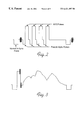
- FIGS. 1-1C show the vertical interval of standard NTSC video signal
- FIG. 2 shows a copy protected signal including pseudo sync pulses and AGC pulses as described in the '603 patent
- FIG. 3 shows a copy protection signal as described in the '098 patent
- FIG. 4 shows a general block diagram of a first embodiment of the invention
- FIG. 5 shows a voltage controlled amplifier or modulator embodiment of “Circuit ACP” depicted in FIG. 4;
- FIG. 6 shows a switch to modify copy protection pulses as another embodiment of “Circuit ACP” depicted in FIG. 4;
- FIG. 7 shows a summing amplifier embodiment of “Circuit ACP” depicted in FIG. 4;
- FIG. 8 shows a combination of circuits as shown in FIGS. 5, 6 , and 7 ;
- FIG. 9 shows a block diagram of a second embodiment of the invention.
- FIG. 1 shows the vertical interval of standard NTSC video signal. Note that the color burst or chroma in the horizontal blanking interval signal is not present during the first nine lines of each field.
- the first includes signals in the Vertical Blanking portion of the video signal.
- the second which will be discussed below includes copy protection signals in the Back Porch portion of the video signal.
- FIG. 2 shows a one horizontal line within a vertical blanking interval of the copy protection signal including pseudo sync pulses and AGC pulses as described in the '603 patent.
- the key element of this signal as described in the '603 patent is the relationship of the pseudo sync pulse with the AGC Pulse. This relationship is the cause of the AGC disturbance in a recorder recording the copy protected signal.
- the elements of these copy protection signals are the combination of either a pseudo sync or a regular sync pulse with an AGC pulse. These pairs sync and AGC pulses are designed to cause the AGC circuitry in a recorder to miscalculate the proper gain setting and thus make an inferior recording.
- the primary object of the embodiments discussed below is to locate the copy protection signal using the Color Burst Signal and to modify a copy protected signal to reduce or eliminate the effects of the copy protection signals.
- FIG. 3 shows a commercial embodiment of the copy protection signal as described in the '098 patent. This signal is placed on several horizontal lines prior to the pre-equalizing pulses of the vertical interval in each field. The combination of these pulses with the pulses in FIG. 2 increases the effectiveness of the copy protection without reducing the playability of the signal on a display device.
- FIG. 4 is an over all block diagram of an embodiment of the invention.
- This embodiment comprises two primary elements.
- the first of these is a novel pseudo sync AGC pulse location circuit that unlike that of the '901, '965, '510 patents.
- the second is a “generic” Circuit ACP” that modifies the copy protection signal under the control of a control pulses generated by the location circuitry.
- the referenced patents use the vertical and horizontal synchronizing signals within the video signal to detect the location of the copy protection pulses.
- the present invention senses color burst or chroma in the horizontal blanking interval to detect the copy protection pulses.
- the color burst or chroma in the horizontal blanking interval signal is not present in the first nine lines of each field.
- the copy protection pulses are in known locations relative to the period containing no color burst or chroma in the horizontal blanking interval signals.
- FIG. 4 shows a novel pseudo sync AGC pulse location circuit that unlike '901, '965, and '501 patents, does not sense sync pulses to locate the copy protection pulses. Instead the embodiment of FIG. 4 relies on color burst or chroma in the horizontal blanking interval.
- Device 10 has an Copy Protected Input Video Signal 12 which is inputted to a “Circuit ACP” 14 and to a Chroma Band Pass Amplifier 16 .
- Chroma Band Pass Amplifier 16 separates the chroma signal from the luminance signal.
- the Band Passed Chroma Signal 18 is coupled to Envelope Detector Amplifier 20 .
- the color burst or chroma in the horizontal blanking interval signal is missing for about 9 lines in the vertical blanking interval.
- the circuitry of FIG. 4 takes advantage of this.
- Chroma Envelope Detector Amplifier 20 is coupled to Non-retriggerable One Shot 22 (timing circuit) of about 52 microseconds to 54 microseconds (less than one TV line). This insures that the output of this circuit triggers off only burst and not chroma in the active TV line and field.
- the output of the Chroma Envelope Detector Amplifier 20 goes also to a Retriggerable One Shot 24 (timing circuit) of about 70 microseconds (greater than one line), an interval that must be greater than 1 TV line but preferably less than 2 TV lines (less than 126 microseconds).
- the output of this 70 microsecond one shot is a pulse high from about line 10 to the end of the TV field (and possible high for 1 line into the next TV field). Since the AGC pulses and Pseudo sync pulses are known to be for lines 10 through 16 or 20 , a 6-10 TV Line One Shot 26 triggers of the low to high transition of the 70 microsecond one shot into Logical ‘AND’ Circuit 28 with the 52-54 microsecond one shot output (active pixel location) that produces Pseudo sync AGC Pulse pixel and line location pulses suitable to control ‘Circuit ACP’ as to attenuate, clip, blank, level shift, enlarge normal sync pulses relative pseudo sync pulses, narrow and modify the copy protection pulses sufficiently as to allow a recordable copy into a video tape recorder.
- the second portion of FIG. 4 is the use of Control Pulse 30 to control the modification of the copy protection signals within Circuit ACP 14 .
- the Copy Protected Video 12 is inputted to a first input of Circuit ACP as signal to be modified by Circuit ACP 14 .
- a second input of Circuit ACP is the above mention Control Signal 30 .
- a first embodiment of Circuit ACP 14 uses a voltage controlled amplifier or modulator to for instance, increase the gain during the normal composite sync pulses and video outside the VBI but excluding the pseudo syncs. During the pseudo sync and/or AGC pulses the gain can be turned down. This is done via Control Signal 30 .
- FIG. 5 shows Circuit ACP 14 with such a voltage controlled amplifier. Copy Protection Video 12 is inputted to an input of Voltage Controlled Amplifier 34 . Control Signal 30 is inputted to the control element of Voltage Controlled Amplifier 34 . This produces a voltage controlled output 32 that will perform the various function described above.
- the use of the voltage controlled amplifier is used to change the relative position of the pseudo sync pulses to the normal sync pulses (for example) as shown in FIG.
- FIG. 6 Another embodiment (FIG. 6) of Circuit ACP 14 uses a switch and a signal generator to modify the copy protected added pulses.
- the signal generator produces a signal representing a blanking level
- the control signal can be used to replace the added pulses with a signal that allows a recordable copy.
- the signal generator may be used to generate any signal including random noise or a test signal, or some variations of the input signal may include a modified version (i.e. narrowed pseudo sync pulses or AGC pulses, level shifted copy protected pulses, enlarged sync pulses and/or a filtered version of the copy protection pulses may be used (i.e. bandpass, low pass, high pass) so as to produce distorted copy protection pulses.
- This signal would replace or modify the copy protection signals so as to allow a recordable copy.
- FIG. 6 shows Circuit ACP 14 with such a switch generator combination.
- Video Copy Signal 12 containing copy protection pulses is inputted to an input of Switch 38 .
- Control Signal 30 is inputted to the control element of Switch 38 .
- the second signal input to Switch 38 is a Video Signal 40 which is generated by Generator 42 .
- the use of the Switch 38 and Generator 42 replaces the Copy Protection pulses within Video Input 12 with a blanking level signal or some other signal i.e. modified part or all of copy protection signals or test signal, thus permitting a normal recording of the Video Input Signal 12 by a recorder.
- a fourth embodiment of Circuit ACP 14 uses a summing circuit to level shift the pseudo syncs such that the VCR's circuitry does not sense the level shifted pseudo syncs.
- a recordable copy can be made.
- the level can be turned varied. This is done via Control Signal 30 .
- FIG. 7 shows Circuit ACP 14 with such a summing circuit. Copy Protection Video 12 is inputted to an input of a summing circuit 44 .
- Control Signal 30 is inputted to the control element of summing circuit 44 . This produces a level shifted output that will perform the various function described above.
- the use of the level shifting signal is used to change the relative position of the pseudo sync pulses to the normal sync pulses as shown in FIG. 3 ( e ) of the '965 patent (incorporated by reference).
- the changing of the relative position of the normal sync pulses to the pseudo sync pulses will cause the AGC system within a recorder to not respond sufficiently to the pseudo sync pulses. This is discussed further at Column 4, lines 22-29 of the '965 patent.
- FIG. 8 shows a combination of the various Circuit ACP embodiments described above in one package. These include Summing Circuit 44 , Voltage Controlled Amplifier 34 and a combination nation of Switch 38 and Voltage Generator 42 and narrowing via the Control Alt signal into SW 99 and nulling (attenuation via SW 9 and Sum 9 .
- the control signal is a logic high representing at least a portion of the time when AGC and or portion of the time when AGC and/or pseudo sync pulses are on.
- circuit ACP variations can be circuits that turn logic high by sensing the copy protected video's AGC and pseudo sync pulses. Then using timing generators to output pulses shorter in duration of the AGC and pseudo syncs, which in turn is used to narrow the video's AGC pulses and pseudo sync pulses.
- the copy protection pulses may also be a combination of narrowing, attenuation, level shifting and or modification(i.e. replacement).
- the '098 and '603 patents also disclose copy protection techniques located on one or more lines within the back porch of a video signal.
- the general concepts of the instant invention can be used to eliminate or reduce the effectiveness of these signals.
- FIG. 9 shows an embodiment to detect the position of the copy protection pulses as depicted in the '098 patent.
- a very simple example would be to couple the chroma envelope pulse from the Chroma Pulse Detector directly to Circuit ACP.
- the present embodiment senses color burst or chroma in the horizontal blanking interval to detect the copy protection pulses.
- the color burst or chroma in the horizontal blanking interval signal is not present in the first nine lines of each field.
- the copy protection pulses are in known locations relative to the period containing no color burst or chroma in the horizontal blanking interval signals.
- Device 50 has an Copy Protected Input Video Signal 12 which is inputted to a “Circuit ACP” 14 and to a Chroma Band Pass Amplifier 16 .
- Chroma Band Pass Amplifier 16 separates the chroma signal from the luminance signal.
- the Band Passed Chroma Signal 18 is coupled to Envelope Detector Amplifier 20 to generate a Chroma Envelope Pulse.
- FIGS. 1A, 1 B and 1 C the color burst or chroma in the horizontal blanking interval signal is missing for about 9 lines in the vertical blanking interval.
- the circuitry of FIG. 9 takes advantage of this.
- Chroma Envelope Detector Amplifier 20 is coupled to One Shot 54 (timing circuit) of about 200 to 250 TV lines.
- a One Shot 64 triggers off One Shot 54 's output to generate a pulse coincident with the pulses described in the '098 patent. These lines are, for example, the last three lines of the field. This insures that the output of this circuit triggers off the area of the picture known to have copy protection signals within the Back Porch of the video signal.
- the width of these pulses can be made adjustable to accommodate variations of copy protection systems that may incorporate copy protection pulses over greater portions of the picture than presently used.
- the outputs of Retriggerable One Shot 64 and the Chroma Envelope Detector Amplifier 20 are coupled into Logical ‘AND’ Circuit 28 that produces Back Porch AGC Pulse pixel to control ‘Circuit ACP’ as to attenuate, clip, blank, replace or level shift the copy protection pulses as to allow a recordable copy into a video tape recorder.
- the output of Chroma Envelope Detector Amplifier 20 is coupled to One Shot 54 (timing circuit) of about 200 to 250 TV lines.
- a One Shot 64 triggers off One Shot 54 's output to generate a pulse coincident with the pulses described in the '098 patent. These lines are, for example, the last three lines of the field.
- the width of these pulses can be made adjustable to accommodate variations of copy protection systems that may incorporate copy protection pulses over greater portions of the picture than presently used.
- the outputs of Retriggerable One Shot 64 and the Chroma Envelope Detector Amplifier 20 are coupled into Logical ‘AND’ Circuit 28 that produces Back Porch AGC Pulse pixel to control ‘Circuit ACP’ as to attenuate, clip, blank, replace or level shift the copy protection pulses as to allow a recordable copy into a video tape recorder.
- Circuit ACP can be used in this embodiment to level shift the copy protection pulse, limit the bandwidth to pass only chroma or replace the copy protection pulse with a normal color burst and blanking level.
Abstract
Description
Claims (9)
Priority Applications (1)
| Application Number | Priority Date | Filing Date | Title |
|---|---|---|---|
| US09/414,747 US6421497B1 (en) | 1995-10-17 | 1999-10-08 | Method for locating copy protection pulses within selected video lines of a video signal |
Applications Claiming Priority (3)
| Application Number | Priority Date | Filing Date | Title |
|---|---|---|---|
| US568195P | 1995-10-17 | 1995-10-17 | |
| US08/733,302 US6002830A (en) | 1995-10-17 | 1996-10-17 | Method and apparatus for removing or defeating effects of copy protection signals from a video signal |
| US09/414,747 US6421497B1 (en) | 1995-10-17 | 1999-10-08 | Method for locating copy protection pulses within selected video lines of a video signal |
Related Parent Applications (1)
| Application Number | Title | Priority Date | Filing Date |
|---|---|---|---|
| US08/733,302 Division US6002830A (en) | 1995-10-17 | 1996-10-17 | Method and apparatus for removing or defeating effects of copy protection signals from a video signal |
Publications (1)
| Publication Number | Publication Date |
|---|---|
| US6421497B1 true US6421497B1 (en) | 2002-07-16 |
Family
ID=21717156
Family Applications (4)
| Application Number | Title | Priority Date | Filing Date |
|---|---|---|---|
| US08/733,302 Expired - Lifetime US6002830A (en) | 1995-10-17 | 1996-10-17 | Method and apparatus for removing or defeating effects of copy protection signals from a video signal |
| US09/137,357 Expired - Lifetime US5953417A (en) | 1995-10-17 | 1998-08-20 | Method and apparatus for digitally removing or defeating effects of copy protection signals from a video signal |
| US09/414,912 Expired - Lifetime US6173109B1 (en) | 1995-10-17 | 1999-10-08 | Method and apparatus for removing or defeating effects of copy protection signals from a video signal |
| US09/414,747 Expired - Lifetime US6421497B1 (en) | 1995-10-17 | 1999-10-08 | Method for locating copy protection pulses within selected video lines of a video signal |
Family Applications Before (3)
| Application Number | Title | Priority Date | Filing Date |
|---|---|---|---|
| US08/733,302 Expired - Lifetime US6002830A (en) | 1995-10-17 | 1996-10-17 | Method and apparatus for removing or defeating effects of copy protection signals from a video signal |
| US09/137,357 Expired - Lifetime US5953417A (en) | 1995-10-17 | 1998-08-20 | Method and apparatus for digitally removing or defeating effects of copy protection signals from a video signal |
| US09/414,912 Expired - Lifetime US6173109B1 (en) | 1995-10-17 | 1999-10-08 | Method and apparatus for removing or defeating effects of copy protection signals from a video signal |
Country Status (12)
| Country | Link |
|---|---|
| US (4) | US6002830A (en) |
| EP (4) | EP0890261B1 (en) |
| JP (2) | JP4355819B2 (en) |
| KR (2) | KR100489145B1 (en) |
| CN (2) | CN1164113C (en) |
| AT (2) | ATE477678T1 (en) |
| AU (3) | AU700093B2 (en) |
| CA (2) | CA2234971C (en) |
| DE (2) | DE69635555T2 (en) |
| HK (1) | HK1015100A1 (en) |
| NZ (2) | NZ323128A (en) |
| WO (2) | WO1997015142A1 (en) |
Cited By (13)
| Publication number | Priority date | Publication date | Assignee | Title |
|---|---|---|---|---|
| US20040062527A1 (en) * | 2002-09-30 | 2004-04-01 | Tokuji Kuroda | Video signal recording apparatus |
| US20050084102A1 (en) * | 2003-10-07 | 2005-04-21 | Hollar Mark A. | Method and apparatus for conveying rights across an analog video interface |
| US20050108612A1 (en) * | 2000-06-01 | 2005-05-19 | Daniel Downing | Secure digital video disk and player |
| US20050195327A1 (en) * | 2003-08-26 | 2005-09-08 | Chupp Christopher E. | Method and system for enhanced modulation of video signals |
| US20060093139A1 (en) * | 2004-10-28 | 2006-05-04 | Macrovision Corporation | Defeat method and apparatus for content management for high definition television |
| US7110042B1 (en) * | 2001-11-07 | 2006-09-19 | Pixelworks, Inc. | Synchronization signal decoder and associated method |
| US20060251252A1 (en) * | 2005-05-06 | 2006-11-09 | Macrovision Corporation | Method and apparatus for modifying a subsequently generated control command in a content control system |
| US20080309816A1 (en) * | 2007-06-15 | 2008-12-18 | Macrovision Corporation | Television content control system and method with cross-platform capability |
| US20090141793A1 (en) * | 2007-11-29 | 2009-06-04 | Koplar Interactive Systems International, L.L.C. | Dual channel encoding and detection |
| US20090317057A1 (en) * | 2008-06-24 | 2009-12-24 | Hua Wu | Apparatus and method for selectively outputting hd/sd signals as high definition video according to copy protection |
| US7664175B1 (en) | 2004-06-16 | 2010-02-16 | Koplar Interactive Systems International, L.L.C. | Mark-based content modulation and detection |
| US20100054469A1 (en) * | 2008-08-27 | 2010-03-04 | Macrovision Solutions Corporation | Method and apparatus for synthesizing copy protection for reducing/defeating the effectiveness or capability of a circumvention device |
| US20110206343A1 (en) * | 2010-02-24 | 2011-08-25 | Rovi Technologies Corporation | Method and apparatus for receiving metadata, epg, or ipg signals in an integrated circuit for control purposes |
Families Citing this family (43)
| Publication number | Priority date | Publication date | Assignee | Title |
|---|---|---|---|---|
| ATE207274T1 (en) * | 1995-05-09 | 2001-11-15 | Macrovision Corp | METHOD AND APPARATUS FOR ELIMINating THE CONSEQUENCES OF CHANGE IN THE COLOR BURST SIGNAL IN A TELEVISION SIGNAL |
| US6516132B1 (en) * | 1995-05-09 | 2003-02-04 | Macrovision Corp | Method and apparatus for improving the effects of color burst modifications to a video signal |
| KR100489145B1 (en) * | 1995-10-17 | 2005-09-14 | 매크로비젼 코포레이션 | Method and apparatus for digitally removing the effects of video anti-copy signals from video signals |
| DK0891669T3 (en) * | 1996-04-01 | 2000-12-18 | Macrovision Corp | Method for managing copy protection of signal material transmitted via digital networks |
| US7395545B2 (en) * | 1997-03-31 | 2008-07-01 | Macrovision Corporation | Method and apparatus for providing copy protection using a transmittal mode command |
| JP3891230B2 (en) * | 1997-05-29 | 2007-03-14 | ソニー株式会社 | Additional information superimposing apparatus and additional information superimposing method |
| US6404889B1 (en) | 1997-06-30 | 2002-06-11 | Macrovision Corporation | Protection of a component video signal |
| US6295360B1 (en) | 1997-06-30 | 2001-09-25 | Macrovision Corporation | Method and apparatus to defeat composite video signal protection |
| JP4003096B2 (en) * | 1997-09-01 | 2007-11-07 | ソニー株式会社 | Method and apparatus for superimposing additional information on video signal |
| US6141488A (en) | 1997-09-05 | 2000-10-31 | United Video Properties, Inc. | Program guide system for recording television programs |
| US6459795B1 (en) * | 1998-02-26 | 2002-10-01 | Macrovision Corporation | Method and apparatus for enhancing the scrambling of a TV signal via erroneous clamp signals |
| US6600873B1 (en) * | 1998-03-20 | 2003-07-29 | Macrovision Corporation | Method and apparatus for detecting modified color burst signals to prevent the copying of a video program |
| US6137952A (en) * | 1998-04-02 | 2000-10-24 | Hewlett-Packard Company | Apparatus and method for degrading the quality of unauthorized copies of color images and video sequences |
| AU4407199A (en) * | 1998-05-20 | 1999-12-06 | Recording Industry Association Of America | Copy protection method using broken modulation rules |
| US6345099B1 (en) * | 1998-05-22 | 2002-02-05 | S3 Incorporated | System and method for copy protecting computer graphics |
| JP3613333B2 (en) * | 1998-09-02 | 2005-01-26 | マクロビジョン・コーポレーション | Method and apparatus for synthesizing and blocking video copy protection signals |
| US6836549B1 (en) | 1998-09-02 | 2004-12-28 | Macrovision Corporation | Method and apparatus for synthesizing and reducing the effects of video copy protection signals |
| EP1480456A1 (en) * | 1998-09-02 | 2004-11-24 | Macrovision Corporation | Method and apparatus to reduce the effects of video copy protection signals |
| US7092043B2 (en) | 1998-11-12 | 2006-08-15 | Broadcom Corporation | Fully integrated tuner architecture |
| US7634089B1 (en) | 1999-10-29 | 2009-12-15 | Sarnoff Corporation | Cinema anti-piracy measures |
| US7324646B1 (en) | 1999-10-29 | 2008-01-29 | Sarnoff Corporation | Method and apparatus for film anti-piracy |
| FR2808957B1 (en) * | 2000-05-11 | 2003-10-24 | Dominique Patrick Bryszkowski | ECONOMIC ELECTRONIC DEVICES DESACHIVING OR ATTENUATING THE EFFECTS OF ANTI-COPY SIGNALS INSERTED IN A VIDEO SIGNAL AND AUTHORIZING COPY |
| US20050063256A1 (en) * | 2000-06-30 | 2005-03-24 | Selinfreund Richard H. | Data storage in optical discs |
| US7124944B2 (en) * | 2000-06-30 | 2006-10-24 | Verification Technologies, Inc. | Product packaging including digital data |
| WO2002002301A1 (en) | 2000-06-30 | 2002-01-10 | Verification Technologies Inc. | Copy-protected optical media and method of manufacture thereof |
| US6638593B2 (en) | 2000-06-30 | 2003-10-28 | Verification Technologies, Inc. | Copy-protected optical media and method of manufacture thereof |
| US7660415B2 (en) | 2000-08-03 | 2010-02-09 | Selinfreund Richard H | Method and apparatus for controlling access to storage media |
| US7050698B1 (en) * | 2000-08-15 | 2006-05-23 | Macrovision Corporation | Method and apparatus for synthesizing or modifying a copy protection signal using a lowered signal level portion |
| US7599604B2 (en) * | 2001-12-14 | 2009-10-06 | Thomson Licensing | Asynchronous copy protection detector |
| US20050084645A1 (en) * | 2002-02-07 | 2005-04-21 | Selinfreund Richard H. | Method and system for optical disc copy-protection |
| JP3789838B2 (en) * | 2002-03-26 | 2006-06-28 | 三洋電機株式会社 | Display device |
| JP2004064369A (en) * | 2002-07-29 | 2004-02-26 | Toshiba Corp | Apparatus and method for detecting signal for preventing reproduction |
| US7398008B2 (en) * | 2002-09-19 | 2008-07-08 | Hewlett-Packard Development Company, L.P. | Copy protection for analog video signals from computing devices |
| WO2004029914A1 (en) * | 2002-09-26 | 2004-04-08 | Verification Technologies, Inc. | Authentication of items using transient optical state change materials |
| US20060203700A1 (en) * | 2003-02-06 | 2006-09-14 | Verification Technologies, Inc. | Method and system for optical disk copy-protection |
| KR20050070953A (en) | 2003-12-31 | 2005-07-07 | 삼성전자주식회사 | Analogue/digital signal processing apparatus for outputting the analogue input signal without eliminating the copy protection signal included therein and method thereof |
| US20060023598A1 (en) * | 2004-07-30 | 2006-02-02 | Babinski James P | Method and apparatus for protecting against copying of content recorded on optical recording media |
| DE102004046618A1 (en) * | 2004-09-25 | 2006-03-30 | Robert Bosch Gmbh | Circuit arrangement for analog / digital conversion |
| US7907727B2 (en) * | 2004-10-19 | 2011-03-15 | Rovi Solutions Corporation | System and method for allowing copying or distribution of a copy protected signal |
| US7784103B2 (en) * | 2004-10-19 | 2010-08-24 | Rovi Solutions Corporation | Method and apparatus for storing copy protection information separately from protected content |
| US20080100597A1 (en) * | 2006-10-25 | 2008-05-01 | Macrovision Corporation | Method and apparatus to improve playability in overscan areas of a TV display |
| TWI357186B (en) * | 2008-10-17 | 2012-01-21 | Wistron Corp | Electronic card connector, electronic decoding dev |
| US10945051B1 (en) | 2020-04-06 | 2021-03-09 | Bank Of America Corporation | System and method for intentionally distorting digital media to reduce the accuracy of generative machine learning algorithms |
Citations (13)
| Publication number | Priority date | Publication date | Assignee | Title |
|---|---|---|---|---|
| US4571615A (en) * | 1983-06-10 | 1986-02-18 | General Instrument Corporation | Timing generator for sync suppressed television signals |
| US4631603A (en) * | 1985-04-17 | 1986-12-23 | Macrovision | Method and apparatus for processing a video signal so as to prohibit the making of acceptable video tape recordings thereof |
| US4695901A (en) * | 1986-03-04 | 1987-09-22 | Macrovision | Method and apparatus for removing pseudo-sync and/or agc pulses from a video signal |
| US4907093A (en) * | 1986-08-11 | 1990-03-06 | Macrovision Corporation | Method and apparatus for preventing the copying of a video program |
| US5157510A (en) * | 1990-12-20 | 1992-10-20 | Macrovision Corporation | Method and apparatus for disabling anti-copy protection system in video signals using pulse narrowing |
| US5179452A (en) * | 1987-07-29 | 1993-01-12 | Scitec Corporation | Method for producing copy protected recorded videotape having uncopyable vertical synchronizing signal partition |
| US5194965A (en) * | 1983-11-23 | 1993-03-16 | Macrovision Corporation | Method and apparatus for disabling anti-copy protection system in video signals |
| US5315448A (en) * | 1993-03-18 | 1994-05-24 | Macrovision Corporation | Copy protection for hybrid digital video tape recording and unprotected source material |
| US5625691A (en) * | 1993-05-17 | 1997-04-29 | Macrovision Corporation | Method and apparatus to defeat certain copy protection pulses within a video signal |
| US5784523A (en) * | 1995-05-09 | 1998-07-21 | Macrovision Corporation | Method and apparatus for defeating effects of color burst modifications to a video signal |
| US5883959A (en) * | 1996-04-18 | 1999-03-16 | Sony Corporation | Video copy protection |
| US6002830A (en) * | 1995-10-17 | 1999-12-14 | Macrovision Corporation | Method and apparatus for removing or defeating effects of copy protection signals from a video signal |
| US6058191A (en) * | 1997-02-04 | 2000-05-02 | Macrovision Corp | Method and apparatus for modifying the envelope of a RF carrier signal to remove copy protection signals therefrom |
Family Cites Families (7)
| Publication number | Priority date | Publication date | Assignee | Title |
|---|---|---|---|---|
| US4336554A (en) * | 1980-06-23 | 1982-06-22 | Clarion Co., Ltd. | Code signal blanking apparatus |
| US4577216A (en) * | 1983-11-14 | 1986-03-18 | Macrovision | Method and apparatus for modifying the color burst to prohibit videotape recording |
| US4819098A (en) * | 1983-11-23 | 1989-04-04 | Macrovision Corporation | Method and apparatus for clustering modifications made to a video signal to inhibit the making of acceptable videotape recordings |
| US4742543A (en) * | 1983-12-22 | 1988-05-03 | Frederiksen Jeffrey E | Video transmission system |
| US4626890A (en) * | 1984-07-03 | 1986-12-02 | Macrovision | Method and apparatus for removing phase modulation from the color burst |
| US4937679A (en) * | 1986-08-11 | 1990-06-26 | Macrovision | Dual deck video recording apparatus having enhanced copy protection and method for providing enhanced copy protection to such a recording apparatus |
| US5058157A (en) * | 1989-09-06 | 1991-10-15 | Macrovision Corporation | Method and apparatus for encrypting and decrypting time domain signals |
-
1996
- 1996-10-17 KR KR10-1998-0702786A patent/KR100489145B1/en not_active IP Right Cessation
- 1996-10-17 EP EP96940248A patent/EP0890261B1/en not_active Expired - Lifetime
- 1996-10-17 NZ NZ323128A patent/NZ323128A/en not_active IP Right Cessation
- 1996-10-17 AT AT96940248T patent/ATE477678T1/en not_active IP Right Cessation
- 1996-10-17 WO PCT/US1996/016783 patent/WO1997015142A1/en active IP Right Grant
- 1996-10-17 EP EP04001551A patent/EP1416730A3/en not_active Ceased
- 1996-10-17 WO PCT/US1996/016767 patent/WO1997016022A1/en active IP Right Grant
- 1996-10-17 DE DE69635555T patent/DE69635555T2/en not_active Expired - Lifetime
- 1996-10-17 DE DE69638231T patent/DE69638231D1/en not_active Expired - Lifetime
- 1996-10-17 AT AT96936734T patent/ATE312475T1/en not_active IP Right Cessation
- 1996-10-17 CN CNB96197642XA patent/CN1164113C/en not_active Expired - Lifetime
- 1996-10-17 JP JP51606497A patent/JP4355819B2/en not_active Expired - Lifetime
- 1996-10-17 KR KR10-1998-0702882A patent/KR100474124B1/en not_active IP Right Cessation
- 1996-10-17 NZ NZ321300A patent/NZ321300A/en unknown
- 1996-10-17 CA CA002234971A patent/CA2234971C/en not_active Expired - Lifetime
- 1996-10-17 JP JP51667497A patent/JP4450434B2/en not_active Expired - Lifetime
- 1996-10-17 CA CA002234972A patent/CA2234972C/en not_active Expired - Lifetime
- 1996-10-17 CN CN96197703A patent/CN1118192C/en not_active Expired - Lifetime
- 1996-10-17 AU AU77183/96A patent/AU700093B2/en not_active Expired
- 1996-10-17 AU AU74580/96A patent/AU700266B2/en not_active Expired
- 1996-10-17 EP EP96936734A patent/EP0856224B1/en not_active Expired - Lifetime
- 1996-10-17 EP EP05026581A patent/EP1646234A3/en not_active Withdrawn
- 1996-10-17 US US08/733,302 patent/US6002830A/en not_active Expired - Lifetime
-
1998
- 1998-08-20 US US09/137,357 patent/US5953417A/en not_active Expired - Lifetime
-
1999
- 1999-01-06 HK HK99100019A patent/HK1015100A1/en not_active IP Right Cessation
- 1999-02-01 AU AU14287/99A patent/AU715473B2/en not_active Expired
- 1999-10-08 US US09/414,912 patent/US6173109B1/en not_active Expired - Lifetime
- 1999-10-08 US US09/414,747 patent/US6421497B1/en not_active Expired - Lifetime
Patent Citations (17)
| Publication number | Priority date | Publication date | Assignee | Title |
|---|---|---|---|---|
| US4571615A (en) * | 1983-06-10 | 1986-02-18 | General Instrument Corporation | Timing generator for sync suppressed television signals |
| US5194965A (en) * | 1983-11-23 | 1993-03-16 | Macrovision Corporation | Method and apparatus for disabling anti-copy protection system in video signals |
| US4631603A (en) * | 1985-04-17 | 1986-12-23 | Macrovision | Method and apparatus for processing a video signal so as to prohibit the making of acceptable video tape recordings thereof |
| US4695901A (en) * | 1986-03-04 | 1987-09-22 | Macrovision | Method and apparatus for removing pseudo-sync and/or agc pulses from a video signal |
| US4695901B1 (en) * | 1986-03-04 | 1990-10-02 | Macrovision | |
| US4907093A (en) * | 1986-08-11 | 1990-03-06 | Macrovision Corporation | Method and apparatus for preventing the copying of a video program |
| US5179452A (en) * | 1987-07-29 | 1993-01-12 | Scitec Corporation | Method for producing copy protected recorded videotape having uncopyable vertical synchronizing signal partition |
| US5157510A (en) * | 1990-12-20 | 1992-10-20 | Macrovision Corporation | Method and apparatus for disabling anti-copy protection system in video signals using pulse narrowing |
| US5315448A (en) * | 1993-03-18 | 1994-05-24 | Macrovision Corporation | Copy protection for hybrid digital video tape recording and unprotected source material |
| US5625691A (en) * | 1993-05-17 | 1997-04-29 | Macrovision Corporation | Method and apparatus to defeat certain copy protection pulses within a video signal |
| US5633927A (en) * | 1993-05-17 | 1997-05-27 | Macrovision Corporation | Video copy protection process enhancement to introduce horizontal and vertical picture distortions |
| US5748733A (en) * | 1993-05-17 | 1998-05-05 | Macrovision Corporation | Method and apparatus to reduce effects of certain copy protection purses within a video signal |
| US5784523A (en) * | 1995-05-09 | 1998-07-21 | Macrovision Corporation | Method and apparatus for defeating effects of color burst modifications to a video signal |
| US6002830A (en) * | 1995-10-17 | 1999-12-14 | Macrovision Corporation | Method and apparatus for removing or defeating effects of copy protection signals from a video signal |
| US6173109B1 (en) * | 1995-10-17 | 2001-01-09 | Macrovision Corporation | Method and apparatus for removing or defeating effects of copy protection signals from a video signal |
| US5883959A (en) * | 1996-04-18 | 1999-03-16 | Sony Corporation | Video copy protection |
| US6058191A (en) * | 1997-02-04 | 2000-05-02 | Macrovision Corp | Method and apparatus for modifying the envelope of a RF carrier signal to remove copy protection signals therefrom |
Cited By (32)
| Publication number | Priority date | Publication date | Assignee | Title |
|---|---|---|---|---|
| US7310764B2 (en) | 2000-06-01 | 2007-12-18 | Macrovision Corporation | Digital video disk and player and associated methods with proprietary format |
| US20050108612A1 (en) * | 2000-06-01 | 2005-05-19 | Daniel Downing | Secure digital video disk and player |
| US7110042B1 (en) * | 2001-11-07 | 2006-09-19 | Pixelworks, Inc. | Synchronization signal decoder and associated method |
| US7376337B2 (en) * | 2002-09-30 | 2008-05-20 | Matsushita Electric Industrial Co., Ltd. | Video signal recording apparatus for copyrighted works |
| US20040062527A1 (en) * | 2002-09-30 | 2004-04-01 | Tokuji Kuroda | Video signal recording apparatus |
| US20050195327A1 (en) * | 2003-08-26 | 2005-09-08 | Chupp Christopher E. | Method and system for enhanced modulation of video signals |
| US20100141836A1 (en) * | 2003-08-26 | 2010-06-10 | Koplar Interactive Systems International, Llc | Method and system for enhanced modulation of video signals |
| US20080056351A1 (en) * | 2003-08-26 | 2008-03-06 | Koplar Interactive Systems International, L.L.C. | Method and system for enhanced modulation of video signals |
| US8405772B2 (en) | 2003-08-26 | 2013-03-26 | Koplar Interactive Systems International L.L.C. | Method and system for enhanced modulation of video signals |
| US7586541B2 (en) | 2003-08-26 | 2009-09-08 | Koplar Interactive Systems International, L.L.C. | Method and system for enhanced modulation of video signals |
| US7692723B2 (en) | 2003-08-26 | 2010-04-06 | Koplar Interactive Systems International L.L.C. | Method and system for enhanced modulation of video signals |
| US7865057B2 (en) * | 2003-10-07 | 2011-01-04 | Rovi Solutions Corporation | Method and apparatus for conveying rights across an analog video interface |
| WO2005039176A1 (en) | 2003-10-07 | 2005-04-28 | Macrovision Corporation | Method and apparatus for conveying rights across an analog video interface |
| US20050084102A1 (en) * | 2003-10-07 | 2005-04-21 | Hollar Mark A. | Method and apparatus for conveying rights across an analog video interface |
| US20100166083A1 (en) * | 2004-06-16 | 2010-07-01 | Chupp Christopher E | Mark-based content modulation and detection |
| US8842725B2 (en) | 2004-06-16 | 2014-09-23 | Koplar Interactive Systems International L.L.C. | Mark-based content modulation and detection |
| US7664175B1 (en) | 2004-06-16 | 2010-02-16 | Koplar Interactive Systems International, L.L.C. | Mark-based content modulation and detection |
| US20060093139A1 (en) * | 2004-10-28 | 2006-05-04 | Macrovision Corporation | Defeat method and apparatus for content management for high definition television |
| US8355621B2 (en) | 2004-10-28 | 2013-01-15 | Rovi Solutions Corporation | Content management for a video signal |
| US20060093140A1 (en) * | 2004-10-28 | 2006-05-04 | Macrovision Corporation | Content management for high definition television |
| US20060251252A1 (en) * | 2005-05-06 | 2006-11-09 | Macrovision Corporation | Method and apparatus for modifying a subsequently generated control command in a content control system |
| US7792293B2 (en) * | 2005-05-06 | 2010-09-07 | Rovi Solutions Corporation | Method and apparatus for modifying a subsequently generated control command in a content control system |
| US20100290620A1 (en) * | 2005-05-06 | 2010-11-18 | Ronald Quan | Method and apparatus for modifying a subsequently generated control command in a content control system |
| US8374347B2 (en) | 2005-05-06 | 2013-02-12 | Rovi Solutions Corporation | Method and apparatus for modifying a subsequently generated control command in a content control system |
| US20080309816A1 (en) * | 2007-06-15 | 2008-12-18 | Macrovision Corporation | Television content control system and method with cross-platform capability |
| US20090141793A1 (en) * | 2007-11-29 | 2009-06-04 | Koplar Interactive Systems International, L.L.C. | Dual channel encoding and detection |
| US8798133B2 (en) | 2007-11-29 | 2014-08-05 | Koplar Interactive Systems International L.L.C. | Dual channel encoding and detection |
| US20090317057A1 (en) * | 2008-06-24 | 2009-12-24 | Hua Wu | Apparatus and method for selectively outputting hd/sd signals as high definition video according to copy protection |
| US20100054469A1 (en) * | 2008-08-27 | 2010-03-04 | Macrovision Solutions Corporation | Method and apparatus for synthesizing copy protection for reducing/defeating the effectiveness or capability of a circumvention device |
| US8280049B2 (en) * | 2008-08-27 | 2012-10-02 | Rovi Solutions Corporation | Method and apparatus for synthesizing copy protection for reducing/defeating the effectiveness or capability of a circumvention device |
| US20110206343A1 (en) * | 2010-02-24 | 2011-08-25 | Rovi Technologies Corporation | Method and apparatus for receiving metadata, epg, or ipg signals in an integrated circuit for control purposes |
| US8374490B2 (en) | 2010-02-24 | 2013-02-12 | Rovi Technologies Corporation | Method and apparatus for receiving metadata, EPG, or IPG signals in an integrated circuit for control purposes |
Also Published As
Similar Documents
| Publication | Publication Date | Title |
|---|---|---|
| US6421497B1 (en) | Method for locating copy protection pulses within selected video lines of a video signal | |
| WO1997015142A9 (en) | Method and apparatus for removing or defeating effects of copy protection signals from a video signal | |
| EP0858219B1 (en) | Method and apparatus for disabling anti-copy protection system in video signals | |
| AU700816B2 (en) | Method and apparatus for defeating effects of color burst modifications to a video signal | |
| US7805056B2 (en) | Methods and apparatus for providing cycles of normal and non normal phase in a color burst signal | |
| US5737417A (en) | Videotape anti-copying encryption scheme | |
| US6600873B1 (en) | Method and apparatus for detecting modified color burst signals to prevent the copying of a video program | |
| AU707280B2 (en) | Method of adaptive control of the presence of a copy protection signal | |
| US6411713B1 (en) | Method of adaptive control of the presence of a copy protection signal | |
| AU720847B2 (en) | Method and apparatus for detecting modified color burst signals to prevent the copying of a video program | |
| JP3089495B2 (en) | Video signal processing device |
Legal Events
| Date | Code | Title | Description |
|---|---|---|---|
| STCF | Information on status: patent grant |
Free format text: PATENTED CASE |
|
| FEPP | Fee payment procedure |
Free format text: PAT HOLDER NO LONGER CLAIMS SMALL ENTITY STATUS, ENTITY STATUS SET TO UNDISCOUNTED (ORIGINAL EVENT CODE: STOL); ENTITY STATUS OF PATENT OWNER: LARGE ENTITY |
|
| REFU | Refund |
Free format text: REFUND - SURCHARGE, PETITION TO ACCEPT PYMT AFTER EXP, UNINTENTIONAL (ORIGINAL EVENT CODE: R2551); ENTITY STATUS OF PATENT OWNER: LARGE ENTITY |
|
| FPAY | Fee payment |
Year of fee payment: 4 |
|
| AS | Assignment |
Owner name: JPMORGAN CHASE BANK, N.A., NEW YORK Free format text: SECURITY AGREEMENT;ASSIGNORS:APTIV DIGITAL, INC.;GEMSTAR DEVELOPMENT CORPORATION;GEMSTAR-TV GUIDE INTERNATIONAL, INC.;AND OTHERS;REEL/FRAME:020986/0074 Effective date: 20080502 Owner name: JPMORGAN CHASE BANK, N.A.,NEW YORK Free format text: SECURITY AGREEMENT;ASSIGNORS:APTIV DIGITAL, INC.;GEMSTAR DEVELOPMENT CORPORATION;GEMSTAR-TV GUIDE INTERNATIONAL, INC.;AND OTHERS;REEL/FRAME:020986/0074 Effective date: 20080502 |
|
| FPAY | Fee payment |
Year of fee payment: 8 |
|
| AS | Assignment |
Owner name: ROVI DATA SOLUTIONS, INC. (FORMERLY KNOWN AS TV GU Free format text: RELEASE BY SECURED PARTY;ASSIGNOR:JPMORGAN CHASE BANK, N.A. (A NATIONAL ASSOCIATION);REEL/FRAME:025222/0731 Effective date: 20100317 Owner name: ODS PROPERTIES, INC., CALIFORNIA Free format text: RELEASE BY SECURED PARTY;ASSIGNOR:JPMORGAN CHASE BANK, N.A. (A NATIONAL ASSOCIATION);REEL/FRAME:025222/0731 Effective date: 20100317 Owner name: APTIV DIGITAL, INC., CALIFORNIA Free format text: RELEASE BY SECURED PARTY;ASSIGNOR:JPMORGAN CHASE BANK, N.A. (A NATIONAL ASSOCIATION);REEL/FRAME:025222/0731 Effective date: 20100317 Owner name: ROVI SOLUTIONS CORPORATION (FORMERLY KNOWN AS MACR Free format text: RELEASE BY SECURED PARTY;ASSIGNOR:JPMORGAN CHASE BANK, N.A. (A NATIONAL ASSOCIATION);REEL/FRAME:025222/0731 Effective date: 20100317 Owner name: TV GUIDE ONLINE, LLC, CALIFORNIA Free format text: RELEASE BY SECURED PARTY;ASSIGNOR:JPMORGAN CHASE BANK, N.A. (A NATIONAL ASSOCIATION);REEL/FRAME:025222/0731 Effective date: 20100317 Owner name: STARSIGHT TELECAST, INC., CALIFORNIA Free format text: RELEASE BY SECURED PARTY;ASSIGNOR:JPMORGAN CHASE BANK, N.A. (A NATIONAL ASSOCIATION);REEL/FRAME:025222/0731 Effective date: 20100317 Owner name: ALL MEDIA GUIDE, LLC, CALIFORNIA Free format text: RELEASE BY SECURED PARTY;ASSIGNOR:JPMORGAN CHASE BANK, N.A. (A NATIONAL ASSOCIATION);REEL/FRAME:025222/0731 Effective date: 20100317 Owner name: ROVI TECHNOLOGIES CORPORATION, CALIFORNIA Free format text: RELEASE BY SECURED PARTY;ASSIGNOR:JPMORGAN CHASE BANK, N.A. (A NATIONAL ASSOCIATION);REEL/FRAME:025222/0731 Effective date: 20100317 Owner name: ROVI GUIDES, INC. (FORMERLY KNOWN AS GEMSTAR-TV GU Free format text: RELEASE BY SECURED PARTY;ASSIGNOR:JPMORGAN CHASE BANK, N.A. (A NATIONAL ASSOCIATION);REEL/FRAME:025222/0731 Effective date: 20100317 Owner name: UNITED VIDEO PROPERTIES, INC., CALIFORNIA Free format text: RELEASE BY SECURED PARTY;ASSIGNOR:JPMORGAN CHASE BANK, N.A. (A NATIONAL ASSOCIATION);REEL/FRAME:025222/0731 Effective date: 20100317 Owner name: TV GUIDE, INC., CALIFORNIA Free format text: RELEASE BY SECURED PARTY;ASSIGNOR:JPMORGAN CHASE BANK, N.A. (A NATIONAL ASSOCIATION);REEL/FRAME:025222/0731 Effective date: 20100317 Owner name: GEMSTAR DEVELOPMENT CORPORATION, CALIFORNIA Free format text: RELEASE BY SECURED PARTY;ASSIGNOR:JPMORGAN CHASE BANK, N.A. (A NATIONAL ASSOCIATION);REEL/FRAME:025222/0731 Effective date: 20100317 Owner name: INDEX SYSTEMS INC., CALIFORNIA Free format text: RELEASE BY SECURED PARTY;ASSIGNOR:JPMORGAN CHASE BANK, N.A. (A NATIONAL ASSOCIATION);REEL/FRAME:025222/0731 Effective date: 20100317 Owner name: ROVI SOLUTIONS LIMITED (FORMERLY KNOWN AS MACROVIS Free format text: RELEASE BY SECURED PARTY;ASSIGNOR:JPMORGAN CHASE BANK, N.A. (A NATIONAL ASSOCIATION);REEL/FRAME:025222/0731 Effective date: 20100317 |
|
| AS | Assignment |
Owner name: JPMORGAN CHASE BANK, N.A., AS COLLATERAL AGENT, NE Free format text: SECURITY INTEREST;ASSIGNORS:APTIV DIGITAL, INC., A DELAWARE CORPORATION;GEMSTAR DEVELOPMENT CORPORATION, A CALIFORNIA CORPORATION;INDEX SYSTEMS INC, A BRITISH VIRGIN ISLANDS COMPANY;AND OTHERS;REEL/FRAME:027039/0168 Effective date: 20110913 |
|
| FPAY | Fee payment |
Year of fee payment: 12 |
|
| AS | Assignment |
Owner name: MORGAN STANLEY SENIOR FUNDING, INC., AS COLLATERAL AGENT, MARYLAND Free format text: PATENT SECURITY AGREEMENT;ASSIGNORS:APTIV DIGITAL, INC.;GEMSTAR DEVELOPMENT CORPORATION;INDEX SYSTEMS INC.;AND OTHERS;REEL/FRAME:033407/0035 Effective date: 20140702 Owner name: MORGAN STANLEY SENIOR FUNDING, INC., AS COLLATERAL Free format text: PATENT SECURITY AGREEMENT;ASSIGNORS:APTIV DIGITAL, INC.;GEMSTAR DEVELOPMENT CORPORATION;INDEX SYSTEMS INC.;AND OTHERS;REEL/FRAME:033407/0035 Effective date: 20140702 Owner name: INDEX SYSTEMS INC., CALIFORNIA Free format text: PATENT RELEASE;ASSIGNOR:JPMORGAN CHASE BANK, N.A., AS COLLATERAL AGENT;REEL/FRAME:033396/0001 Effective date: 20140702 Owner name: ROVI SOLUTIONS CORPORATION, CALIFORNIA Free format text: PATENT RELEASE;ASSIGNOR:JPMORGAN CHASE BANK, N.A., AS COLLATERAL AGENT;REEL/FRAME:033396/0001 Effective date: 20140702 Owner name: UNITED VIDEO PROPERTIES, INC., CALIFORNIA Free format text: PATENT RELEASE;ASSIGNOR:JPMORGAN CHASE BANK, N.A., AS COLLATERAL AGENT;REEL/FRAME:033396/0001 Effective date: 20140702 Owner name: ROVI GUIDES, INC., CALIFORNIA Free format text: PATENT RELEASE;ASSIGNOR:JPMORGAN CHASE BANK, N.A., AS COLLATERAL AGENT;REEL/FRAME:033396/0001 Effective date: 20140702 Owner name: GEMSTAR DEVELOPMENT CORPORATION, CALIFORNIA Free format text: PATENT RELEASE;ASSIGNOR:JPMORGAN CHASE BANK, N.A., AS COLLATERAL AGENT;REEL/FRAME:033396/0001 Effective date: 20140702 Owner name: ALL MEDIA GUIDE, LLC, CALIFORNIA Free format text: PATENT RELEASE;ASSIGNOR:JPMORGAN CHASE BANK, N.A., AS COLLATERAL AGENT;REEL/FRAME:033396/0001 Effective date: 20140702 Owner name: APTIV DIGITAL, INC., CALIFORNIA Free format text: PATENT RELEASE;ASSIGNOR:JPMORGAN CHASE BANK, N.A., AS COLLATERAL AGENT;REEL/FRAME:033396/0001 Effective date: 20140702 Owner name: ROVI TECHNOLOGIES CORPORATION, CALIFORNIA Free format text: PATENT RELEASE;ASSIGNOR:JPMORGAN CHASE BANK, N.A., AS COLLATERAL AGENT;REEL/FRAME:033396/0001 Effective date: 20140702 Owner name: ROVI CORPORATION, CALIFORNIA Free format text: PATENT RELEASE;ASSIGNOR:JPMORGAN CHASE BANK, N.A., AS COLLATERAL AGENT;REEL/FRAME:033396/0001 Effective date: 20140702 Owner name: TV GUIDE INTERNATIONAL, INC., CALIFORNIA Free format text: PATENT RELEASE;ASSIGNOR:JPMORGAN CHASE BANK, N.A., AS COLLATERAL AGENT;REEL/FRAME:033396/0001 Effective date: 20140702 Owner name: STARSIGHT TELECAST, INC., CALIFORNIA Free format text: PATENT RELEASE;ASSIGNOR:JPMORGAN CHASE BANK, N.A., AS COLLATERAL AGENT;REEL/FRAME:033396/0001 Effective date: 20140702 |
|
| AS | Assignment |
Owner name: INDEX SYSTEMS INC., CALIFORNIA Free format text: RELEASE OF SECURITY INTEREST IN PATENT RIGHTS;ASSIGNOR:MORGAN STANLEY SENIOR FUNDING, INC., AS COLLATERAL AGENT;REEL/FRAME:051145/0090 Effective date: 20191122 Owner name: ROVI TECHNOLOGIES CORPORATION, CALIFORNIA Free format text: RELEASE OF SECURITY INTEREST IN PATENT RIGHTS;ASSIGNOR:MORGAN STANLEY SENIOR FUNDING, INC., AS COLLATERAL AGENT;REEL/FRAME:051145/0090 Effective date: 20191122 Owner name: VEVEO, INC., CALIFORNIA Free format text: RELEASE OF SECURITY INTEREST IN PATENT RIGHTS;ASSIGNOR:MORGAN STANLEY SENIOR FUNDING, INC., AS COLLATERAL AGENT;REEL/FRAME:051145/0090 Effective date: 20191122 Owner name: GEMSTAR DEVELOPMENT CORPORATION, CALIFORNIA Free format text: RELEASE OF SECURITY INTEREST IN PATENT RIGHTS;ASSIGNOR:MORGAN STANLEY SENIOR FUNDING, INC., AS COLLATERAL AGENT;REEL/FRAME:051145/0090 Effective date: 20191122 Owner name: ROVI GUIDES, INC., CALIFORNIA Free format text: RELEASE OF SECURITY INTEREST IN PATENT RIGHTS;ASSIGNOR:MORGAN STANLEY SENIOR FUNDING, INC., AS COLLATERAL AGENT;REEL/FRAME:051145/0090 Effective date: 20191122 Owner name: APTIV DIGITAL INC., CALIFORNIA Free format text: RELEASE OF SECURITY INTEREST IN PATENT RIGHTS;ASSIGNOR:MORGAN STANLEY SENIOR FUNDING, INC., AS COLLATERAL AGENT;REEL/FRAME:051145/0090 Effective date: 20191122 Owner name: ROVI SOLUTIONS CORPORATION, CALIFORNIA Free format text: RELEASE OF SECURITY INTEREST IN PATENT RIGHTS;ASSIGNOR:MORGAN STANLEY SENIOR FUNDING, INC., AS COLLATERAL AGENT;REEL/FRAME:051145/0090 Effective date: 20191122 Owner name: UNITED VIDEO PROPERTIES, INC., CALIFORNIA Free format text: RELEASE OF SECURITY INTEREST IN PATENT RIGHTS;ASSIGNOR:MORGAN STANLEY SENIOR FUNDING, INC., AS COLLATERAL AGENT;REEL/FRAME:051145/0090 Effective date: 20191122 Owner name: STARSIGHT TELECAST, INC., CALIFORNIA Free format text: RELEASE OF SECURITY INTEREST IN PATENT RIGHTS;ASSIGNOR:MORGAN STANLEY SENIOR FUNDING, INC., AS COLLATERAL AGENT;REEL/FRAME:051145/0090 Effective date: 20191122 Owner name: SONIC SOLUTIONS LLC, CALIFORNIA Free format text: RELEASE OF SECURITY INTEREST IN PATENT RIGHTS;ASSIGNOR:MORGAN STANLEY SENIOR FUNDING, INC., AS COLLATERAL AGENT;REEL/FRAME:051145/0090 Effective date: 20191122 |