US6421082B1 - Forming images on receivers having field-driven particles - Google Patents
Forming images on receivers having field-driven particles Download PDFInfo
- Publication number
- US6421082B1 US6421082B1 US09/067,627 US6762798A US6421082B1 US 6421082 B1 US6421082 B1 US 6421082B1 US 6762798 A US6762798 A US 6762798A US 6421082 B1 US6421082 B1 US 6421082B1
- Authority
- US
- United States
- Prior art keywords
- receiver
- cartridge
- image
- field
- pixels
- Prior art date
- Legal status (The legal status is an assumption and is not a legal conclusion. Google has not performed a legal analysis and makes no representation as to the accuracy of the status listed.)
- Expired - Fee Related
Links
Images


Classifications
-
- H—ELECTRICITY
- H04—ELECTRIC COMMUNICATION TECHNIQUE
- H04N—PICTORIAL COMMUNICATION, e.g. TELEVISION
- H04N1/00—Scanning, transmission or reproduction of documents or the like, e.g. facsimile transmission; Details thereof
- H04N1/21—Intermediate information storage
- H04N1/2104—Intermediate information storage for one or a few pictures
- H04N1/2112—Intermediate information storage for one or a few pictures using still video cameras
- H04N1/2154—Intermediate information storage for one or a few pictures using still video cameras the still video camera incorporating a hardcopy reproducing device, e.g. a printer
-
- H—ELECTRICITY
- H04—ELECTRIC COMMUNICATION TECHNIQUE
- H04N—PICTORIAL COMMUNICATION, e.g. TELEVISION
- H04N1/00—Scanning, transmission or reproduction of documents or the like, e.g. facsimile transmission; Details thereof
- H04N1/0035—User-machine interface; Control console
- H04N1/00405—Output means
- H04N1/00408—Display of information to the user, e.g. menus
- H04N1/0044—Display of information to the user, e.g. menus for image preview or review, e.g. to help the user position a sheet
-
- H—ELECTRICITY
- H04—ELECTRIC COMMUNICATION TECHNIQUE
- H04N—PICTORIAL COMMUNICATION, e.g. TELEVISION
- H04N1/00—Scanning, transmission or reproduction of documents or the like, e.g. facsimile transmission; Details thereof
- H04N1/21—Intermediate information storage
- H04N1/2104—Intermediate information storage for one or a few pictures
- H04N1/2112—Intermediate information storage for one or a few pictures using still video cameras
-
- H—ELECTRICITY
- H04—ELECTRIC COMMUNICATION TECHNIQUE
- H04N—PICTORIAL COMMUNICATION, e.g. TELEVISION
- H04N2101/00—Still video cameras
Definitions
- the present invention relates to an insertable cartridge having receivers with field-driven particles.
- electrophoretic particle that is based on the principle of movement of charged particles in an electric field.
- electrophoretic receiver the charged particles containing different reflective optical densities can be moved by an electric field to or away from the viewing side of the receiver, which produces a contrast in the optical density.
- Another class of electric field-driven particles are particles carrying an electric dipole. Each pole of the particle is associated with a different optical densities (bi-chromatic). The electric dipole can be aligned by a pair of electrodes in two directions, which orient each of the two polar surfaces to the viewing direction. The different optical densities on the two halves of the particles thus produces a contrast in the optical densities.
- the electric fields can be produced by a plurality pairs of electrodes embodied in the receiver as disclosed in U.S. Pat. No. 3,612,758.
- a shortcoming with prior electronic cameras is that data must be transmitted from the electronic camera to printer. Interfaces must be present to transfer the data. As disclosed in U.S. Pat. No. No. 5,032,911, printers that write to light sensitive media print must have means within the printer that operate on received data and convert the data into modulated light to mark the photosensitive sheet. Many newer electronic cameras incorporate light emitting displays to view a captured image. However, the apparatus for producing such images is not available for light writing onto photosensitive media.
- an insertable cartridge for insertion into a receiving structure having electronic addressing means for forming a visual image of a stored image comprising:
- a housing for receiving a plurality of receivers, each receiver including field-driven particles in a matrix that can change reflective density in response to an applied electric field which intersect at positions corresponding to pixels;
- the housing defining alignment features for insertion into the receiving structure which receives and positions an inserted cartridge
- the housing including electronic interconnecting means for connection between the addressing means and a receiver after a cartridge has been inserted in the receiving structure for permitting the application of voltages at the pixel positions across the field-driven particles at particular locations in the receiver corresponding to pixels in the stored image to produce an image in the receiver in the cartridge.
- a feature of this invention is that an insertable cartridge having a plurality of receivers with field-driven particles and that images can be formed in the cartridge on the top receiver.
- the cartridge housing can be provided with electrical interconnection which, when the cartridge is inserted into a receiving structure such as a printer or a camera, are interconnected with addressing means for addressing pixel positions on the top receiver.
- FIG. 1 is a front perspective of an electronic camera which can receive an insertable cartridge in accordance with the present invention
- FIG. 2 a is a left side view of the electronic camera of FIG. 1 showing the insertable cartridge slot with a cartridge positioned in such slot;
- FIG. 2 b is a top sectional view taken along the lines 1 — 1 of the electronic camera of FIG. 1;
- FIG. 3 is an electrical block diagram of circuitry in the camera for addressing interconnecting circuitry in the cartridge for forming an image on the top receiver in the cartridge;
- FIG. 4 shows a partial top view of the offset circular tracks 50 of FIG. 1 and the layout of the electrodes of offset circular tracks 50 ;
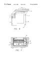
- FIG. 5 a is a cross sectional similar to that shown in FIG. 7, but only of the cartridge;
- FIG. 5 b is an detailed partial enlargement of the cross sectional view of FIG. 5 a showing the receiver electrodes in contact with the electronic interconnection assembly
- FIG. 6 is a perspective of a flex circuit forming the electronic interconnect with a cutaway view of the pins which contact the offset circular tracks 50 ;
- FIG. 7 is a cross sectional view of the insertable cartridge while inserted in a receiving body showing the effect of the alignment features of the insertable cartridge.
- the invention is directed to an insertable cartridge 40 which is inserted into a receiving structure for forming images.
- the receiving structure can be a compact printer or an electronic camera 10 .
- images are formed on the top receiver 20 .
- the present invention will be described in connection with electronic camera 10 although other printer arrangements will suggest themselves to those skilled in the art.
- Such electronic cameras often have a flat panel color display that is used to frame and/or review capture images.
- Separable printers exist that receive data from said electronic cameras.
- interface electronics is disposed in each device and data is transmitted from the electronic camera to the printer.
- an electronic camera 10 is shown. It is of conventional design and includes shutter button 2 , control information display 4 , electronic flash assembly 6 , optical viewfinder 8 , and lens system 14 . Highly unconventional is the ability of the camera to accept the insertable cartridge 40 for forming hardcopy images on its enclosed receiver sheets.
- an electronic display 3 is mounted on the rear surface of the camera 10 for displaying an image before a hardcopy print on the top receiver 20 of a stack of receivers is made.
- An access door 5 can be removed so that a print can be taken from the camera 10 .
- the camera 10 is also shown to include a camera circuit board 11 and an area image sensor 12 shown more fully in FIG. 3 .
- the camera also includes a lens system 14 .
- the insertable cartridge 40 has been inserted into a slot formed in a camera housing 54 which will be described more fully hereinafter.
- the electronic camera 10 can be of a conventional design and can capture either still images or temporally spaced sequences of still images. Images are captured by the area image sensor 12 after an image of subject S has been focused by the lens system 14 onto such area image sensor 12 .
- the electronic camera 10 can include the electronic display 3 for showing an image prior to its being produced on the top receiver 20 so that a user can decide whether or not it is appropriate to make a hardcopy image.
- Electronic display 3 can be, for instance, a LCD or organic polymer display system of conventional design.
- Electronic camera 10 includes features for receiving the insertable cartridge 40 . These features are shown in FIG. 7 and include two triangular tracks 52 formed in the camera housing 54 . Ball bearings 56 are disposed in the triangular tracks 52 allowing the insertable cartridge 40 to be slideably inserted into a slot 58 formed in the camera housing 54 . Offset circular tracks 50 disposed on either side of the insertable cartridge 40 permit the insertion into slot 58 of electronic camera 10 .
- Insertable cartridge 40 further includes a vertical pressure plate 60 which is urged by a spring 62 so as to cause the receivers positioned on the pressure plate 60 to be moved so that the top most top receiver 20 will be in a image transfer relationship with an electrode header 64 which is shown in FIG. 6.
- a lateral pressure plate 76 is urged by a spring 78 against the sides of the receivers in a stack on the pressure plate 60 to properly laterally position the receivers.
- the electrode header 64 includes a plurality of electrodes 66 which engage traces 68 formed on the top most receiver to provide electrical connection for the application of voltages which will be described more fully in FIG. 3 .
- traces 68 formed on the top most receiver to provide electrical connection for the application of voltages which will be described more fully in FIG. 3 .
- the electrodes connect the appropriate traces to cause an electric field to be applied at the pixel position in the top receiver 20 .
- the electrode header 64 is secured to a flexible circuit 70 which is in turn secured by means of pins 72 to the side wall of the cartridge housing 55 as shown in FIG. 5 a and FIG. 7 .
- the flexible circuit 70 includes a number of leads 74 which provide electronic interconnects 42 shown in FIG. 3 .
- Electronic interconnects 42 together with electrode header 64 and electrodes 66 connect address drivers 36 (FIG. 3) to traces 68 on top receiver 20 for forming a hardcopy print.
- the top receiver 20 includes field driven particles disposed in a matrix.
- These field driven particles can be conventional.
- the field-driven particles can include many different types, for example, the bi-chromatic dipolar particles and electrophoretic particles.
- the following disclosures are herein incorporated in the present invention. Details of the fabrication of the bi-chromatic dipolar particles and their addressing configuration are disclosed in U.S. Pat. Nos. 4,143,103; 5,344,594; and 5,604,027, and in “A Newly Developed Electrical Twisting Ball Display” by Saitoh et al p249-253, Proceedings of the SID, Vol. 23/4, 1982, the disclosure of these references are incorporated herein by reference.
- Another type of field-driven particle is disclosed in PCT Patent Application WO 97/04398. It is understood that the present invention is compatible with many other types of field-driven particles that can display different color densities under the influence of an applied electrical field.
- an image of the subject, S is focused by lens system 14 .
- a conventional focus control 33 can automatically adjust the lens system 14 to focus an image of the subject S on the area image sensor 12 .
- Conventional signal processing circuitry 35 receives signals from the area image sensor 12 and applies its signal under the control of central processing unit 34 .
- the central processing unit 34 controls the operation of various functions for example the I/O interface 30 , reading and writing from memory 32 , the signal processing circuitry 35 , the display 3 and address drivers 36 .
- the I/O interface 30 will be understood to include circuitry necessary for connection to external devices such as delivery of a digital image to another computer or input from a camera user. All these circuits are conventional and need not be described in detail here.
- the central processing unit 34 in response to digital images stored in memory 32 provides control signals to address drivers 36 .
- the address drivers 36 provide control voltages to appropriate leads 74 (see FIG. 6) which form the electronic interconnections with electrodes 66 as discussed earlier.
- the electronic interconnects 42 are schematically shown to be within the cartridge 40 .
- electrodes 66 provide applied voltages to appropriate traces on top receiver 20 .
Abstract
Description
Claims (5)
Priority Applications (1)
| Application Number | Priority Date | Filing Date | Title |
|---|---|---|---|
| US09/067,627 US6421082B1 (en) | 1998-04-28 | 1998-04-28 | Forming images on receivers having field-driven particles |
Applications Claiming Priority (1)
| Application Number | Priority Date | Filing Date | Title |
|---|---|---|---|
| US09/067,627 US6421082B1 (en) | 1998-04-28 | 1998-04-28 | Forming images on receivers having field-driven particles |
Publications (1)
| Publication Number | Publication Date |
|---|---|
| US6421082B1 true US6421082B1 (en) | 2002-07-16 |
Family
ID=22077292
Family Applications (1)
| Application Number | Title | Priority Date | Filing Date |
|---|---|---|---|
| US09/067,627 Expired - Fee Related US6421082B1 (en) | 1998-04-28 | 1998-04-28 | Forming images on receivers having field-driven particles |
Country Status (1)
| Country | Link |
|---|---|
| US (1) | US6421082B1 (en) |
Cited By (1)
| Publication number | Priority date | Publication date | Assignee | Title |
|---|---|---|---|---|
| US6909456B1 (en) * | 1999-07-14 | 2005-06-21 | Fuji Photo Film Co., Ltd. | Electronic still camera with printer |
Citations (9)
| Publication number | Priority date | Publication date | Assignee | Title |
|---|---|---|---|---|
| US3612758A (en) | 1969-10-03 | 1971-10-12 | Xerox Corp | Color display device |
| US4143103A (en) | 1976-05-04 | 1979-03-06 | Xerox Corporation | Method of making a twisting ball panel display |
| US5032911A (en) | 1989-04-28 | 1991-07-16 | Fuji Photo Film Co., Ltd. | Video image printer using liquid crystal light valves and primary auxiliary direction scanning |
| US5344594A (en) | 1991-10-29 | 1994-09-06 | Xerox Corporation | Method for the fabrication of multicolored balls for a twisting ball display |
| WO1997004398A2 (en) | 1995-07-20 | 1997-02-06 | Jacobson Joseph M | Electronic book with multiple page displays |
| US5604027A (en) | 1995-01-03 | 1997-02-18 | Xerox Corporation | Some uses of microencapsulation for electric paper |
| US5790193A (en) * | 1995-11-22 | 1998-08-04 | Eastman Kodak Company | Accessory module for an electronic camera |
| US6118419A (en) * | 1996-10-02 | 2000-09-12 | Xerox Corporation | Random electrostatic discharge event indicator |
| US6323989B1 (en) * | 1996-07-19 | 2001-11-27 | E Ink Corporation | Electrophoretic displays using nanoparticles |
-
1998
- 1998-04-28 US US09/067,627 patent/US6421082B1/en not_active Expired - Fee Related
Patent Citations (10)
| Publication number | Priority date | Publication date | Assignee | Title |
|---|---|---|---|---|
| US3612758A (en) | 1969-10-03 | 1971-10-12 | Xerox Corp | Color display device |
| US4143103A (en) | 1976-05-04 | 1979-03-06 | Xerox Corporation | Method of making a twisting ball panel display |
| US5032911A (en) | 1989-04-28 | 1991-07-16 | Fuji Photo Film Co., Ltd. | Video image printer using liquid crystal light valves and primary auxiliary direction scanning |
| US5344594A (en) | 1991-10-29 | 1994-09-06 | Xerox Corporation | Method for the fabrication of multicolored balls for a twisting ball display |
| US5604027A (en) | 1995-01-03 | 1997-02-18 | Xerox Corporation | Some uses of microencapsulation for electric paper |
| WO1997004398A2 (en) | 1995-07-20 | 1997-02-06 | Jacobson Joseph M | Electronic book with multiple page displays |
| US6124851A (en) * | 1995-07-20 | 2000-09-26 | E Ink Corporation | Electronic book with multiple page displays |
| US5790193A (en) * | 1995-11-22 | 1998-08-04 | Eastman Kodak Company | Accessory module for an electronic camera |
| US6323989B1 (en) * | 1996-07-19 | 2001-11-27 | E Ink Corporation | Electrophoretic displays using nanoparticles |
| US6118419A (en) * | 1996-10-02 | 2000-09-12 | Xerox Corporation | Random electrostatic discharge event indicator |
Non-Patent Citations (1)
| Title |
|---|
| "A Newly Developed Electrical Twisting Ball Display" by Saitoh et al p249-253, Proceedings of the SID, vol. 23/4, 1982. |
Cited By (1)
| Publication number | Priority date | Publication date | Assignee | Title |
|---|---|---|---|---|
| US6909456B1 (en) * | 1999-07-14 | 2005-06-21 | Fuji Photo Film Co., Ltd. | Electronic still camera with printer |
Similar Documents
| Publication | Publication Date | Title |
|---|---|---|
| US6525767B2 (en) | Electronic still camera with image pick-up unit and card unit | |
| US5644410A (en) | Image sensing apparatus | |
| US5438359A (en) | Electronic camera system using IC memory card | |
| US20080225156A1 (en) | Digital image processing apparatus with rotating display device | |
| US6734915B2 (en) | Cradle-installation type digital camera, control method therefor and cradle-installation type digital camera system | |
| JP2000158676A (en) | Insertable cartridge for apparatus with ink-jet printer | |
| US20060034039A1 (en) | Apparatus with display | |
| CN110463181A (en) | Liquid lens and camara module and optical device including camara module | |
| US5742861A (en) | Electronic camera and associated printer which uses a display image | |
| US6421082B1 (en) | Forming images on receivers having field-driven particles | |
| KR100695075B1 (en) | Duel-lense assembly and image photography apparatus | |
| JPH10239779A (en) | Electronic camera and related printer having optical shutter | |
| US6894718B2 (en) | Continual-image processing device for printing or displaying images | |
| JP2000228742A (en) | Electronic camera | |
| JP3610263B2 (en) | Electronic camera | |
| JP2967602B2 (en) | Memory card holder and camera | |
| CN1383048A (en) | Digital camera able to change format of visiting card and its method | |
| JP2001108969A (en) | Liquid crystal device, and video recording and reproducing device provided with the same | |
| JP3965529B2 (en) | Digital camera | |
| JPS6234144A (en) | Camera | |
| JPS6234143A (en) | Camera | |
| JPH11243499A (en) | View finder device | |
| TW508471B (en) | Digital module for camera to obtain digital image | |
| JP2007115648A (en) | Tilt sensor and camera using it | |
| JP2016175359A (en) | White board |
Legal Events
| Date | Code | Title | Description |
|---|---|---|---|
| AS | Assignment |
Owner name: EASTMAN KODAK COMPANY, NEW YORK Free format text: ASSIGNMENT OF ASSIGNORS INTEREST;ASSIGNORS:MCINTYRE, DALE F.;MACLEAN, STEVEN D.;WEN, XIN;REEL/FRAME:009171/0161;SIGNING DATES FROM 19980312 TO 19980313 |
|
| FEPP | Fee payment procedure |
Free format text: PAYOR NUMBER ASSIGNED (ORIGINAL EVENT CODE: ASPN); ENTITY STATUS OF PATENT OWNER: LARGE ENTITY |
|
| FPAY | Fee payment |
Year of fee payment: 4 |
|
| FPAY | Fee payment |
Year of fee payment: 8 |
|
| AS | Assignment |
Owner name: CITICORP NORTH AMERICA, INC., AS AGENT, NEW YORK Free format text: SECURITY INTEREST;ASSIGNORS:EASTMAN KODAK COMPANY;PAKON, INC.;REEL/FRAME:028201/0420 Effective date: 20120215 |
|
| AS | Assignment |
Owner name: WILMINGTON TRUST, NATIONAL ASSOCIATION, AS AGENT, Free format text: PATENT SECURITY AGREEMENT;ASSIGNORS:EASTMAN KODAK COMPANY;PAKON, INC.;REEL/FRAME:030122/0235 Effective date: 20130322 Owner name: WILMINGTON TRUST, NATIONAL ASSOCIATION, AS AGENT, MINNESOTA Free format text: PATENT SECURITY AGREEMENT;ASSIGNORS:EASTMAN KODAK COMPANY;PAKON, INC.;REEL/FRAME:030122/0235 Effective date: 20130322 |
|
| AS | Assignment |
Owner name: BANK OF AMERICA N.A., AS AGENT, MASSACHUSETTS Free format text: INTELLECTUAL PROPERTY SECURITY AGREEMENT (ABL);ASSIGNORS:EASTMAN KODAK COMPANY;FAR EAST DEVELOPMENT LTD.;FPC INC.;AND OTHERS;REEL/FRAME:031162/0117 Effective date: 20130903 Owner name: BARCLAYS BANK PLC, AS ADMINISTRATIVE AGENT, NEW YORK Free format text: INTELLECTUAL PROPERTY SECURITY AGREEMENT (SECOND LIEN);ASSIGNORS:EASTMAN KODAK COMPANY;FAR EAST DEVELOPMENT LTD.;FPC INC.;AND OTHERS;REEL/FRAME:031159/0001 Effective date: 20130903 Owner name: JPMORGAN CHASE BANK, N.A., AS ADMINISTRATIVE, DELAWARE Free format text: INTELLECTUAL PROPERTY SECURITY AGREEMENT (FIRST LIEN);ASSIGNORS:EASTMAN KODAK COMPANY;FAR EAST DEVELOPMENT LTD.;FPC INC.;AND OTHERS;REEL/FRAME:031158/0001 Effective date: 20130903 Owner name: BARCLAYS BANK PLC, AS ADMINISTRATIVE AGENT, NEW YO Free format text: INTELLECTUAL PROPERTY SECURITY AGREEMENT (SECOND LIEN);ASSIGNORS:EASTMAN KODAK COMPANY;FAR EAST DEVELOPMENT LTD.;FPC INC.;AND OTHERS;REEL/FRAME:031159/0001 Effective date: 20130903 Owner name: EASTMAN KODAK COMPANY, NEW YORK Free format text: RELEASE OF SECURITY INTEREST IN PATENTS;ASSIGNORS:CITICORP NORTH AMERICA, INC., AS SENIOR DIP AGENT;WILMINGTON TRUST, NATIONAL ASSOCIATION, AS JUNIOR DIP AGENT;REEL/FRAME:031157/0451 Effective date: 20130903 Owner name: JPMORGAN CHASE BANK, N.A., AS ADMINISTRATIVE, DELA Free format text: INTELLECTUAL PROPERTY SECURITY AGREEMENT (FIRST LIEN);ASSIGNORS:EASTMAN KODAK COMPANY;FAR EAST DEVELOPMENT LTD.;FPC INC.;AND OTHERS;REEL/FRAME:031158/0001 Effective date: 20130903 Owner name: PAKON, INC., NEW YORK Free format text: RELEASE OF SECURITY INTEREST IN PATENTS;ASSIGNORS:CITICORP NORTH AMERICA, INC., AS SENIOR DIP AGENT;WILMINGTON TRUST, NATIONAL ASSOCIATION, AS JUNIOR DIP AGENT;REEL/FRAME:031157/0451 Effective date: 20130903 |
|
| REMI | Maintenance fee reminder mailed | ||
| LAPS | Lapse for failure to pay maintenance fees | ||
| STCH | Information on status: patent discontinuation |
Free format text: PATENT EXPIRED DUE TO NONPAYMENT OF MAINTENANCE FEES UNDER 37 CFR 1.362 |
|
| FP | Lapsed due to failure to pay maintenance fee |
Effective date: 20140716 |
|
| AS | Assignment |
Owner name: KODAK IMAGING NETWORK, INC., NEW YORK Free format text: RELEASE BY SECURED PARTY;ASSIGNOR:JP MORGAN CHASE BANK, N.A., AS ADMINISTRATIVE AGENT;REEL/FRAME:049814/0001 Effective date: 20190617 Owner name: KODAK (NEAR EAST), INC., NEW YORK Free format text: RELEASE BY SECURED PARTY;ASSIGNOR:JP MORGAN CHASE BANK, N.A., AS ADMINISTRATIVE AGENT;REEL/FRAME:049814/0001 Effective date: 20190617 Owner name: KODAK AVIATION LEASING LLC, NEW YORK Free format text: RELEASE BY SECURED PARTY;ASSIGNOR:JP MORGAN CHASE BANK, N.A., AS ADMINISTRATIVE AGENT;REEL/FRAME:049814/0001 Effective date: 20190617 Owner name: FAR EAST DEVELOPMENT LTD., NEW YORK Free format text: RELEASE BY SECURED PARTY;ASSIGNOR:JP MORGAN CHASE BANK, N.A., AS ADMINISTRATIVE AGENT;REEL/FRAME:049814/0001 Effective date: 20190617 Owner name: KODAK REALTY, INC., NEW YORK Free format text: RELEASE BY SECURED PARTY;ASSIGNOR:JP MORGAN CHASE BANK, N.A., AS ADMINISTRATIVE AGENT;REEL/FRAME:049814/0001 Effective date: 20190617 Owner name: QUALEX, INC., NEW YORK Free format text: RELEASE BY SECURED PARTY;ASSIGNOR:JP MORGAN CHASE BANK, N.A., AS ADMINISTRATIVE AGENT;REEL/FRAME:049814/0001 Effective date: 20190617 Owner name: LASER PACIFIC MEDIA CORPORATION, NEW YORK Free format text: RELEASE BY SECURED PARTY;ASSIGNOR:JP MORGAN CHASE BANK, N.A., AS ADMINISTRATIVE AGENT;REEL/FRAME:049814/0001 Effective date: 20190617 Owner name: PAKON, INC., NEW YORK Free format text: RELEASE BY SECURED PARTY;ASSIGNOR:JP MORGAN CHASE BANK, N.A., AS ADMINISTRATIVE AGENT;REEL/FRAME:049814/0001 Effective date: 20190617 Owner name: KODAK PHILIPPINES, LTD., NEW YORK Free format text: RELEASE BY SECURED PARTY;ASSIGNOR:JP MORGAN CHASE BANK, N.A., AS ADMINISTRATIVE AGENT;REEL/FRAME:049814/0001 Effective date: 20190617 Owner name: FPC, INC., NEW YORK Free format text: RELEASE BY SECURED PARTY;ASSIGNOR:JP MORGAN CHASE BANK, N.A., AS ADMINISTRATIVE AGENT;REEL/FRAME:049814/0001 Effective date: 20190617 Owner name: CREO MANUFACTURING AMERICA LLC, NEW YORK Free format text: RELEASE BY SECURED PARTY;ASSIGNOR:JP MORGAN CHASE BANK, N.A., AS ADMINISTRATIVE AGENT;REEL/FRAME:049814/0001 Effective date: 20190617 Owner name: KODAK PORTUGUESA LIMITED, NEW YORK Free format text: RELEASE BY SECURED PARTY;ASSIGNOR:JP MORGAN CHASE BANK, N.A., AS ADMINISTRATIVE AGENT;REEL/FRAME:049814/0001 Effective date: 20190617 Owner name: KODAK AMERICAS, LTD., NEW YORK Free format text: RELEASE BY SECURED PARTY;ASSIGNOR:JP MORGAN CHASE BANK, N.A., AS ADMINISTRATIVE AGENT;REEL/FRAME:049814/0001 Effective date: 20190617 Owner name: NPEC, INC., NEW YORK Free format text: RELEASE BY SECURED PARTY;ASSIGNOR:JP MORGAN CHASE BANK, N.A., AS ADMINISTRATIVE AGENT;REEL/FRAME:049814/0001 Effective date: 20190617 Owner name: EASTMAN KODAK COMPANY, NEW YORK Free format text: RELEASE BY SECURED PARTY;ASSIGNOR:JP MORGAN CHASE BANK, N.A., AS ADMINISTRATIVE AGENT;REEL/FRAME:049814/0001 Effective date: 20190617 |
|
| AS | Assignment |
Owner name: KODAK REALTY INC., NEW YORK Free format text: RELEASE BY SECURED PARTY;ASSIGNOR:BARCLAYS BANK PLC;REEL/FRAME:052773/0001 Effective date: 20170202 Owner name: KODAK AMERICAS LTD., NEW YORK Free format text: RELEASE BY SECURED PARTY;ASSIGNOR:BARCLAYS BANK PLC;REEL/FRAME:052773/0001 Effective date: 20170202 Owner name: QUALEX INC., NEW YORK Free format text: RELEASE BY SECURED PARTY;ASSIGNOR:BARCLAYS BANK PLC;REEL/FRAME:052773/0001 Effective date: 20170202 Owner name: FAR EAST DEVELOPMENT LTD., NEW YORK Free format text: RELEASE BY SECURED PARTY;ASSIGNOR:BARCLAYS BANK PLC;REEL/FRAME:052773/0001 Effective date: 20170202 Owner name: KODAK (NEAR EAST) INC., NEW YORK Free format text: RELEASE BY SECURED PARTY;ASSIGNOR:BARCLAYS BANK PLC;REEL/FRAME:052773/0001 Effective date: 20170202 Owner name: EASTMAN KODAK COMPANY, NEW YORK Free format text: RELEASE BY SECURED PARTY;ASSIGNOR:BARCLAYS BANK PLC;REEL/FRAME:052773/0001 Effective date: 20170202 Owner name: KODAK PHILIPPINES LTD., NEW YORK Free format text: RELEASE BY SECURED PARTY;ASSIGNOR:BARCLAYS BANK PLC;REEL/FRAME:052773/0001 Effective date: 20170202 Owner name: NPEC INC., NEW YORK Free format text: RELEASE BY SECURED PARTY;ASSIGNOR:BARCLAYS BANK PLC;REEL/FRAME:052773/0001 Effective date: 20170202 Owner name: LASER PACIFIC MEDIA CORPORATION, NEW YORK Free format text: RELEASE BY SECURED PARTY;ASSIGNOR:BARCLAYS BANK PLC;REEL/FRAME:052773/0001 Effective date: 20170202 Owner name: FPC INC., NEW YORK Free format text: RELEASE BY SECURED PARTY;ASSIGNOR:BARCLAYS BANK PLC;REEL/FRAME:052773/0001 Effective date: 20170202 |