US6418775B1 - Method and apparatus for aligning a beam path for a beam-emitting sensor - Google Patents

Method and apparatus for aligning a beam path for a beam-emitting sensor Download PDF

Info

Publication number
US6418775B1
US6418775B1 US09/438,182 US43818299A US6418775B1 US 6418775 B1 US6418775 B1 US 6418775B1 US 43818299 A US43818299 A US 43818299A US 6418775 B1 US6418775 B1 US 6418775B1
Authority
US
United States
Prior art keywords
aligning
vehicle
sensor
projection plane
reflected
Prior art date
Legal status (The legal status is an assumption and is not a legal conclusion. Google has not performed a legal analysis and makes no representation as to the accuracy of the status listed.)
Expired - Lifetime
Application number
US09/438,182
Inventor
Peter Säger
Thomas Landsiedel
Jörg Neugärtner
Current Assignee (The listed assignees may be inaccurate. Google has not performed a legal analysis and makes no representation or warranty as to the accuracy of the list.)
Continental Automotive GmbH
Original Assignee
Siemens AG
Priority date (The priority date is an assumption and is not a legal conclusion. Google has not performed a legal analysis and makes no representation as to the accuracy of the date listed.)
Filing date
Publication date
Application filed by Siemens AG filed Critical Siemens AG
Assigned to MANNESMANN VDO AG reassignment MANNESMANN VDO AG ASSIGNMENT OF ASSIGNORS INTEREST (SEE DOCUMENT FOR DETAILS). Assignors: NEUGARTNER, JORG, LANDSIEDEL, THOMAS, SAGER, PETER
Application granted granted Critical
Publication of US6418775B1 publication Critical patent/US6418775B1/en
Assigned to SIEMENS AKTIENGESELLSCHAFT reassignment SIEMENS AKTIENGESELLSCHAFT MERGER (SEE DOCUMENT FOR DETAILS). Assignors: MANNESMANN VDO AKTIENGESELLSCHAFT
Assigned to CONTINENTAL AUTOMOTIVE GMBH reassignment CONTINENTAL AUTOMOTIVE GMBH ASSIGNMENT OF ASSIGNORS INTEREST (SEE DOCUMENT FOR DETAILS). Assignors: SIEMENS AKTIENGESELLSCHAFT
Anticipated expiration legal-status Critical
Expired - Lifetime legal-status Critical Current

Links

Images

Classifications

    • GPHYSICS
    • G01MEASURING; TESTING
    • G01SRADIO DIRECTION-FINDING; RADIO NAVIGATION; DETERMINING DISTANCE OR VELOCITY BY USE OF RADIO WAVES; LOCATING OR PRESENCE-DETECTING BY USE OF THE REFLECTION OR RERADIATION OF RADIO WAVES; ANALOGOUS ARRANGEMENTS USING OTHER WAVES
    • G01S7/00Details of systems according to groups G01S13/00, G01S15/00, G01S17/00
    • G01S7/48Details of systems according to groups G01S13/00, G01S15/00, G01S17/00 of systems according to group G01S17/00
    • G01S7/497Means for monitoring or calibrating
    • G01S7/4972Alignment of sensor
    • GPHYSICS
    • G01MEASURING; TESTING
    • G01SRADIO DIRECTION-FINDING; RADIO NAVIGATION; DETERMINING DISTANCE OR VELOCITY BY USE OF RADIO WAVES; LOCATING OR PRESENCE-DETECTING BY USE OF THE REFLECTION OR RERADIATION OF RADIO WAVES; ANALOGOUS ARRANGEMENTS USING OTHER WAVES
    • G01S7/00Details of systems according to groups G01S13/00, G01S15/00, G01S17/00
    • G01S7/02Details of systems according to groups G01S13/00, G01S15/00, G01S17/00 of systems according to group G01S13/00
    • G01S7/40Means for monitoring or calibrating
    • G01S7/4004Means for monitoring or calibrating of parts of a radar system
    • G01S7/4026Antenna boresight
    • GPHYSICS
    • G01MEASURING; TESTING
    • G01SRADIO DIRECTION-FINDING; RADIO NAVIGATION; DETERMINING DISTANCE OR VELOCITY BY USE OF RADIO WAVES; LOCATING OR PRESENCE-DETECTING BY USE OF THE REFLECTION OR RERADIATION OF RADIO WAVES; ANALOGOUS ARRANGEMENTS USING OTHER WAVES
    • G01S13/00Systems using the reflection or reradiation of radio waves, e.g. radar systems; Analogous systems using reflection or reradiation of waves whose nature or wavelength is irrelevant or unspecified
    • G01S13/88Radar or analogous systems specially adapted for specific applications
    • G01S13/93Radar or analogous systems specially adapted for specific applications for anti-collision purposes
    • G01S13/931Radar or analogous systems specially adapted for specific applications for anti-collision purposes of land vehicles
    • G01S2013/9327Sensor installation details
    • G01S2013/93271Sensor installation details in the front of the vehicles
    • GPHYSICS
    • G01MEASURING; TESTING
    • G01SRADIO DIRECTION-FINDING; RADIO NAVIGATION; DETERMINING DISTANCE OR VELOCITY BY USE OF RADIO WAVES; LOCATING OR PRESENCE-DETECTING BY USE OF THE REFLECTION OR RERADIATION OF RADIO WAVES; ANALOGOUS ARRANGEMENTS USING OTHER WAVES
    • G01S7/00Details of systems according to groups G01S13/00, G01S15/00, G01S17/00
    • G01S7/02Details of systems according to groups G01S13/00, G01S15/00, G01S17/00 of systems according to group G01S13/00
    • G01S7/40Means for monitoring or calibrating
    • G01S7/4052Means for monitoring or calibrating by simulation of echoes
    • G01S7/4082Means for monitoring or calibrating by simulation of echoes using externally generated reference signals, e.g. via remote reflector or transponder
    • G01S7/4086Means for monitoring or calibrating by simulation of echoes using externally generated reference signals, e.g. via remote reflector or transponder in a calibrating environment, e.g. anechoic chamber

Definitions

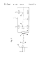
  • the aligning beam before it hits the sensor, the aligning beam appears perpendicularly from a projection plane which the reflected beam hits and forms an image thereon. With the aid of such a projection plane, it is easy to ascertain a deviation between the emitted aligning beam and the reflected aligning beam.

Abstract

A system and method for aligning the beam path of a beam-emitting sensor arranged on a motor vehicle. Convenient and nevertheless highly precise setting of the beam direction of the beam-emitting element is possible if, when the vehicle is stationary, an external aligning beam propagating along or parallel to an actual direction of travel of the motor vehicle 1 hits a strictly planar surface on the sensor which reflects the aligning beam, the incident aligning beam and the reflected aligning beam are made to overlap as a result of the position of the sensor being changed.

Description

BACKGROUND OF THE INVENTION
1. Field of the Invention
The present invention relates to a system and method for aligning the beam path of a beam-emitting sensor arranged on a motor vehicle.
2. Description of the Related Art
In distance regulating systems for motor vehicles, the motor vehicle has a radar or laser sensor which is used to detect one or more objects situated in the vehicle's direction of travel. In order to accomplish this result, the sensor outputs a signal which is reflected by the objects. The reflected beam is received by the sensor again and evaluated in an evaluation circuit. The evaluation circuit performs an analysis of the signals and determines the relative vehicle speed, the distance of the vehicle from the detected object, and the lateral course deviation of the vehicle traveling in front from the vehicle's direction of travel.
If the beam direction of the sensor is imprecise, objects are detected which are not of interest or important to consider. If the wrong vehicle is recognized as being the nearest to the vehicle, the distance regulator is set to this object, which can result in dangerous situations in road traffic and can possibly lead to a collision.
Particularly when determining the lateral deviation of the target from the vehicle's direction of travel, inaccuracies in the angular error may result in significant errors for the calculated lateral course deviation as the distance from the located target increases. Since the sensors used have detection ranges of up to 150 m, then, at this distance, an alignment error angle at the vehicle of one degree would result in an error of approximately 2.9 m. Because the width of the roadway is approximately 3.5 m on average, this means that it is very quickly possible for the target to be incorrectly assigned to the predetermined lane for the vehicle which is to be controlled.
SUMMARY OF THE INVENTION
The present invention is therefore based on the object of specifying a method and a device which can be used to set the beam direction of the beam-emitting element on the motor vehicle conveniently and yet very accurately.
The invention achieves the object in that, when the vehicle is stationary, an external aligning beam hits a strictly planar surface on the sensor which reflects the aligning beam, the incident aligning beam and the reflected aligning beam are made to overlap as a result of the position of the sensor being changed.
The advantage of the method is that the setting accuracy depends only on the accuracy of the positional determination in front of the vehicle, the light source and the projection plane with respect to one another and the position of the reflective surface with respect to the sensor detection range. The absolute position of the reference surface with respect to the projection plane and to the light source is negligible in this case. In addition, there is no need whatsoever to take into consideration the installation tolerances of the system on the vehicle. For example, the absolute position of the sensor with respect to the center of the vehicle or above the ground below or the road is irrelevant. Hence, the influence of undercarriage variants, for example lower sports undercarriages, or manufacturing tolerances in the region of a few centimeters between two vehicles is also eliminated.
The method according to the invention enables the sensor to be aligned reliably both in the horizontal (azimuth) and in the vertical (elevation).
To align the azimuth, the aligning beam propagates along or parallel to an actual direction of travel of the motor vehicle. Since the sensors used can only produce a detection range of a few angular degrees in the horizontal, it is particularly important to be able to set small angular changes reliably as well using the method according to the invention.
The action for aligning the vertical is similar. In this case, the aligning beam is oriented to a planar vehicle tire contact area. The vehicles are aligned when carrying no load at the end of the production line in the factory. Since vehicles are usually loaded when the distance regulator is operating, the position of the detection range with respect to the ideal line (the horizontal) is rotated in elevation. On top of this, vehicles pitch to a very considerable extent when driven, that is to say the vehicle executes a vertical movement about the vehicle's center of gravity. This happens, amongst other times, when starting off and accelerating or when braking. Furthermore, the detection range is also severely limited when the vehicle is climbing and descending.
In one refinement of the invention, before it hits the sensor, the aligning beam appears perpendicularly from a projection plane which the reflected beam hits and forms an image thereon. With the aid of such a projection plane, it is easy to ascertain a deviation between the emitted aligning beam and the reflected aligning beam.
The diameter of the aligning beam is advantageously approximately constant at least in the region between the projection plane and the sensor. In this case, the diameter of the light beam must be selected to be such that the smallest adjustment displacement is many times greater than the diameter of the light beam. This prevents errors in the alignment as a result of expansion of the light beam.
In one embodiment, the aligning beam is a laser beam which has a high constancy over a long path. The light beam can also be an infrared light beam. The vehicle's direction of travel advantageously corresponds to the actual driving axis of the motor vehicle. This actual driving axis is determined using vehicle axle measurement methods which are known per se. Hence, devices such as axle test benches already used today can be used to determine the vehicle driving axis. Additional aids for determining the actual direction of travel of a vehicle are not necessary.
The optical axis of the aligning beam is oriented to the vehicle's direction of travel either by orienting the vehicle or by orienting the aligning beam. In an apparatus for aligning a beam-emitting sensor arranged on the motor vehicle, a radiation source which emits an aligning beam is arranged behind a projection plane which lets through the aligning beam, and the aligning beam which passes through the projection plane hits a reflective surface mounted on the sensor in a repentable position with respect to the sensor. The reflected beam can be imaged on the projection plane via adjustment of a device which locks the sensor on the vehicle and coordinates the image of the reflected aligning beam with the emitted aligning beam in the projection plane.
In this case, the sensor can be arranged on the front, on the rear or else on the sides of the motor vehicle. In one embodiment, the projection plane has an opening through which the aligning beam passes, the center point of the opening coinciding with the optical axis of the light source. This ensures that it is not necessary to switch on the radar sensor or laser sensor for alignment. The precise setting of the beam direction of the sensor is ensured only using external aids.
In one simple embodiment, the projection plane is designed as a matt plate which can image the reflected beam. Hence, information is simply obtained about the direction in which the adjusting device must be moved in order to make the emitted aligning beam and the reflected aligning beam overlap.
A convenient embodiment of the invention is achieved in that the projection plane is designed as an active CCD linear array which is connected to the adjusting device via a control device. This makes electronic evaluation of the distance of the aligning beam from the reflected beam possible. Here too, the control device drives the adjusting device separately in terms of azimuth and elevation, until coordination is obtained.
In one refinement, the reflective surface is formed by an auxiliary device which is locked on the sensor by means of a three-point support. This three-point support gives the auxiliary device a defined position with respect to the reference surfaces and thus with respect to the detection range of the sensor. Each point of the support then correlates to a reference surface on the sensor.
In another refinement, the reflective surface is a reflective surface milled on the sensor housing itself. Auxiliary devices for providing the reflective surface can then be dispensed with. In one simple embodiment, the reflective surface is formed by a reflective plastic surface.
BRIEF DESCRIPTION OF THE DRAWINGS
The invention permits numerous embodiments. One of these will be explained in more detail with the aid of the figures illustrated in the drawing, in which:
FIG. 1 illustrates an embodiment of the distance regulating device on a motor vehicle;
FIG. 2 illustrates an adjusting device;
FIG. 3 illustrates alignment of the azimuth using the apparatus according to the invention;
FIG. 4 illustrates alignment of the elevation using the apparatus according to the invention;
FIG. 5 is an illustration of the projection plane; and
FIG. 6 illustrates automatic adjustment.
The same features are identified by the same reference symbols.
DETAILED DESCRIPTION OF THE PREFERRED EMBODIMENTS
In FIG. 1, an automatic speed and distance regulating system 3 for maintaining the safety distance between vehicles is arranged on the bumper 2 of a motor vehicle 1. The speed and distance regulating system 3 includes a radar sensor and the distance regulating device, which are not shown further. A bus system 4 present in the vehicle 1 connects the automatic speed and distance regulating system 3 to the engine controller 5, the brake 7 or the transmission 8. By intervening in the engine controller 5, the brake 7 or the transmission 8, electronic commands automatically regulate the distance and the speed of the vehicle 1 to be regulated if it approaches a slower vehicle traveling in front. A display unit 6 which is likewise driven by the speed and distance regulating system 3 via the bus system 4, preferably a CAN bus, is used to display the current speed and also the distance from the vehicle traveling in front.
FIG. 2 shows an adjusting device 19 which is mounted on the motor vehicle 1 using screw devices 20. Mounted on the adjusting device 19 is a housing 10 containing the radar sensor. The sensor is distinguished only by its lens 11, which rests on the housing 10 and is arranged perpendicular to the direction of travel.
The adjusting device 19 has a planar angle element 12 whose surface is connected to that surface of the housing 10 which faces the adjusting device 19. The angle element 12 stretches over the entire transverse extent of the sensor housing 10 and has, on each outer region, a respective screw connection 13, which is loosened for the aligning procedure.
To set the azimuth of the sensor beam, an adjusting screw 16 having latching devices 17 is turned, the housing 10 is pivoted about an axis which passes through the housing journal 15. The housing journal 15 is arranged at the center on the surface of the housing 10 and engages in the angle element 12. The distance between two latching devices corresponds to a particular angular change.
The elevation of the sensor beam is set using a further adjusting screw 18, the sensor housing 10 being turned about an axis 14 of the adjusting device 19. FIG. 3 shows an aligning device. This aligning device comprises a light source 21, advantageously a laser, set up in front of the vehicle 1. In front of the laser, there is a projection plane 22 arranged at right angles to the optical axis of the laser 21. The laser beam 23 hits a mirror 25 mounted on the housing 10.
As shown in FIG. 3, the mirror 25 extends over the whole surface of the front of the sensor housing 10 and is locked on the housing 10 by means of three webs 26. This three-point support creates a reproducible and unambiguous position for the mirror 25 with respect to the sensor housing 10. This arrangement means that the mirror 25 follows every possible movement of the radar sensor, and there are no displacements between the mirror and the radar sensor.
The laser beam 27 reflected by the mirror 25 is imaged on the projection plane 22. To determine the vehicle's longitudinal axis 28, the center point 29 between the wheels on the front axle and then the center point 30 between the wheels on the rear axle are established. This difference between the two center points 29 and 30 established in this way corresponds to the deviation of the reflected laser beam 27 from the emitted laser beam 23. By adjusting the azimuth screw 16, the optical axis of the laser 22 is coordinated with the vehicle's longitudinal axis 28. The sensor device thus maintains a direction which enables the sensor beam 9 to be radiated in exactly the vehicle's longitudinal axis during driving.
The process is similar for setting the elevation. The aligning device just described is used, and alignment is performed when the vehicle is empty and stationary, preferably at the place of manufacture. FIG. 4 shows that first the tire contact area for the front axle VA and then the tire contact area for the rear axle HA are measured. Here too, by adjusting the sensor housing 10 by actuating the adjusting screw 18, the sensor beam is set such that the reflected laser beam 27 and the emitted laser beam 23 are coordinated.
FIG. 5 shows the projection plane 22. For orientation purposes, the projection plane 22, designed as a matt glass plate in this case, has a scale shown on it for the driving axis angular errors. In this case, the azimuth is shown in the horizontal and the elevation is shown in the perpendicular. At the center point of this scale, the projection plane 22 has an opening 24 through which the external laser beam 23 passes. Since the reflected luminous radiation 27 is optically visible on the matt plate 22, simply actuating the adjusting screws 16 and 18 on the adjusting device 19 can direct the image of the reflected beam 27 onto the opening 24 in the center of the coordinate system.
A convenient embodiment is shown in FIG. 6, where the projection plane is designed as a CCD linear array 31. In this arrangement, the electrical connections of the CCD linear array 31 are connected to a control device 32, which recognizes the distance between the emitted laser beam 23 and the reflected laser beam 27. A display device 33 is used to indicate to the worker by how many steps he needs to change the azimuth and the elevation, and in which direction, in order to obtain the desired result.
It is also conceivable, however, for the control device 32 to output these differences to the adjusting device 19 automatically via actuating elements 34, and for these actuating elements 34 to perform the latching steps automatically according to the measured difference.

Claims (16)

We claim:
1. A method for aligning a beam path of a beam-emitting sensor on a vehicle comprising the steps of: directing an aligning beam on a surface of a sensor which reflects the aligning beam; and adjusting a position of the sensor to align the incident aligning beam and a reflected aligning beam so that they overlap.
2. The method as claimed in claim 1, wherein the aligning beam propagates at least substantially parallel to an actual direction of travel of the vehicle.
3. The method as claimed in claim 2, wherein the vehicle's direction of travel corresponds to the actual driving axis of the vehicle.
4. The method as claimed in claim 3, further comprising the step of orienting the aligning beam to the vehicle's direction of travel.
5. The method as claimed in claim 1, further comprising a step of orienting the aligning beam to a planar vehicle tire contact area.
6. The method as claimed in claim 1, further comprising a step of directing the reflected aligning beam onto a projection plane.
7. The method as claimed in claim 1, wherein the diameter of the aligning beam is approximately constant, at least in a region between the projection plane and the sensor.
8. The method as claimed in claim 7, wherein the aligning beam is a laser beam or an infrared beam.
9. An apparatus for aligning a beam-emitting sensor on a vehicle comprising:
a radiation source behind a projection plane which allows the aligning beam to move towards a reflective surface mounted on the sensor located on the vehicle and
an adjustment mechanism which locks the sensor on the vehicle making it possible to coordinate the image of the reflected aligning beam with the emitted aligning beam in the projection plane.
10. The apparatus as claimed in claim 9, wherein the projection plane has an opening through which the aligning beam passes.
11. The apparatus as claimed in claim 9, wherein the projection plane is a matt plate.
12. The apparatus as claimed in claim 9, wherein the projection plane is a CCD linear array which is connected to the adjusting device via a control device, the control device driving the adjusting device until the reflected beam is coordinated with the emitted beam.
13. The apparatus as claimed in claim 9, wherein the reflective surface is formed by an auxiliary device which can be locked on the sensor by means of a three-point support.
14. The apparatus as claimed in claim 9, wherein the reflective surface is on the sensor housing.
15. The apparatus as claimed in claim 13, wherein the reflective surface is a reflective plastic surface.
16. The apparatus as claimed in claim 9, wherein the optical axis of the light source coincides with the actual driving axis of the vehicle.
US09/438,182 1998-11-12 1999-11-11 Method and apparatus for aligning a beam path for a beam-emitting sensor Expired - Lifetime US6418775B1 (en)

Applications Claiming Priority (2)

Application Number Priority Date Filing Date Title
DE19852101A DE19852101C2 (en) 1998-11-12 1998-11-12 Method and device for adjusting a beam path of a beam-emitting sensor
DE19852101 1998-11-12

Publications (1)

Publication Number Publication Date
US6418775B1 true US6418775B1 (en) 2002-07-16

Family

ID=7887494

Family Applications (1)

Application Number Title Priority Date Filing Date
US09/438,182 Expired - Lifetime US6418775B1 (en) 1998-11-12 1999-11-11 Method and apparatus for aligning a beam path for a beam-emitting sensor

Country Status (3)

Country Link
US (1) US6418775B1 (en)
EP (1) EP1001274B1 (en)
DE (2) DE19852101C2 (en)

Cited By (12)

* Cited by examiner, † Cited by third party
Publication number Priority date Publication date Assignee Title
US6636172B1 (en) * 1999-08-04 2003-10-21 Bayerische Motoren Werke Aktiengesellschaft Method for adjusting a vehicle-mounted radar sensor
US20050206910A1 (en) * 2004-03-19 2005-09-22 Schroeder Richard A Linear displacement sensor
US20080147274A1 (en) * 2006-12-14 2008-06-19 Bong-Chul Ko Apparatus for alignment adjusting of radar equipped in a vehicle
US20080179900A1 (en) * 2007-01-25 2008-07-31 Ford Motor Company Vehicle mounting and alignment bracket
US20090055117A1 (en) * 2004-07-09 2009-02-26 Hella Kgaa Method And Device For Compensating The Mounting Tolerances Of A Distance Sensor
US20150035703A1 (en) * 2012-02-10 2015-02-05 Robert Bosch Gmbh Radar sensor device having an adjusting mirror
JP2015068746A (en) * 2013-09-30 2015-04-13 日野自動車株式会社 Axis adjustment device and axis adjustment method of on-vehicle radar
CN108120966A (en) * 2017-12-25 2018-06-05 深圳市道通科技股份有限公司 A kind of trailer-mounted radar calibration facility and method
US20210033467A1 (en) * 2018-04-17 2021-02-04 Autel Inteligent Technology Corp., Ltd. Calibration apparatus, system and method for in-vehicle camera
US11009587B2 (en) 2017-06-30 2021-05-18 Bosch Automotive Service Solutions Inc. Portable apparatus, system, and method for calibrating a vehicular electromagnetic sensor
US11579272B2 (en) 2019-12-23 2023-02-14 Toyota Motor Engineering & Manufacturing North America, Inc. Method and reflect array for alignment calibration of frequency modulated LiDAR systems
US11639234B2 (en) * 2019-04-24 2023-05-02 The Boeing Company Method, system and apparatus for aligning a removable sensor on a vehicle

Families Citing this family (12)

* Cited by examiner, † Cited by third party
Publication number Priority date Publication date Assignee Title
DE10042105B4 (en) * 2000-07-12 2010-09-02 Volkswagen Ag Method for adjusting a directional antenna of a radar system
DE10107219B4 (en) * 2001-02-16 2017-09-28 Robert Bosch Gmbh Driving speed and / or adaptive cruise control system
EP1340999A1 (en) * 2002-02-28 2003-09-03 Alignment International Limited Method and apparatus for identifying the position of an object
EP1340998A1 (en) * 2002-02-28 2003-09-03 Alignment International Limited Apparatus and method for identifying the orientation of an object
DE102004004193A1 (en) * 2004-01-27 2005-08-18 Robert Bosch Gmbh Method and device for angular adjustment of a sensor in a motor vehicle
DE102005016718B4 (en) * 2005-04-11 2021-06-10 Audi Ag Method for adjusting object sensors of a motor vehicle
JP2008232887A (en) * 2007-03-22 2008-10-02 Omron Corp Object sensing apparatus and irradiation axis adjustment method
EP2113787B1 (en) 2008-05-02 2014-06-25 Harro Koch Device for monitoring the alignment of radar sensors
DE102010042276A1 (en) * 2010-10-11 2012-04-12 Robert Bosch Gmbh Sensor, adjustment method and measurement method for a sensor
DE102014113070B4 (en) * 2014-09-10 2022-06-30 Knorr-Bremse Systeme für Nutzfahrzeuge GmbH Alignment device and method for aligning a component on a vehicle
DE102017214014A1 (en) * 2017-08-11 2019-02-14 Robert Bosch Gmbh Method for adjusting at least one target on an adjusting device
CA3076342A1 (en) * 2019-04-24 2020-10-24 The Boeing Company Aligning sensors on vehicles using sensor output

Citations (5)

* Cited by examiner, † Cited by third party
Publication number Priority date Publication date Assignee Title
EP0654680A2 (en) 1993-11-22 1995-05-24 State Of Israel Ministry Of Defence Rafael Armament Development Authority Upgrading fire control systems
US5495254A (en) 1992-11-19 1996-02-27 Mazda Motor Corporation Detection and calibration of horizontal error in a scanning type radar device
US5742383A (en) 1996-11-26 1998-04-21 Samsung Electronics Co., Ltd. Apparatus for measuring degree of inclination of objective lens for optical pickup
EP0905526A1 (en) 1997-09-26 1999-03-31 Thomson-Csf Car's radar alignment adjusting device
US6020844A (en) * 1998-01-06 2000-02-01 Hitachi, Ltd. Car on-board radar axis adjusting method

Family Cites Families (3)

* Cited by examiner, † Cited by third party
Publication number Priority date Publication date Assignee Title
DE4201214C1 (en) * 1992-01-18 1993-02-04 Mercedes-Benz Aktiengesellschaft, 7000 Stuttgart, De
DE19642811C2 (en) * 1996-10-17 1999-12-09 Bosch Gmbh Robert Method for adjusting a directional antenna of a radar system and radar system for carrying out the method
DE19707591C1 (en) * 1997-02-26 1998-10-29 Bosch Gmbh Robert Monitoring alignment of beam characteristic of object sensor

Patent Citations (5)

* Cited by examiner, † Cited by third party
Publication number Priority date Publication date Assignee Title
US5495254A (en) 1992-11-19 1996-02-27 Mazda Motor Corporation Detection and calibration of horizontal error in a scanning type radar device
EP0654680A2 (en) 1993-11-22 1995-05-24 State Of Israel Ministry Of Defence Rafael Armament Development Authority Upgrading fire control systems
US5742383A (en) 1996-11-26 1998-04-21 Samsung Electronics Co., Ltd. Apparatus for measuring degree of inclination of objective lens for optical pickup
EP0905526A1 (en) 1997-09-26 1999-03-31 Thomson-Csf Car's radar alignment adjusting device
US6020844A (en) * 1998-01-06 2000-02-01 Hitachi, Ltd. Car on-board radar axis adjusting method

Cited By (19)

* Cited by examiner, † Cited by third party
Publication number Priority date Publication date Assignee Title
US6636172B1 (en) * 1999-08-04 2003-10-21 Bayerische Motoren Werke Aktiengesellschaft Method for adjusting a vehicle-mounted radar sensor
US20050206910A1 (en) * 2004-03-19 2005-09-22 Schroeder Richard A Linear displacement sensor
US20090055117A1 (en) * 2004-07-09 2009-02-26 Hella Kgaa Method And Device For Compensating The Mounting Tolerances Of A Distance Sensor
US7571066B2 (en) * 2004-07-09 2009-08-04 Hella Kgaa Method and device for compensating the mounting tolerances of a distance sensor
US7853374B2 (en) * 2006-12-14 2010-12-14 Hyundai Motor Company Apparatus for alignment adjusting of radar equipped in a vehicle
US20080147274A1 (en) * 2006-12-14 2008-06-19 Bong-Chul Ko Apparatus for alignment adjusting of radar equipped in a vehicle
US8511727B2 (en) 2007-01-25 2013-08-20 Ford Motor Company Vehicle mounting and alignment bracket
US7988212B2 (en) 2007-01-25 2011-08-02 Ford Motor Company Vehicle mounting and alignment bracket
US20080179900A1 (en) * 2007-01-25 2008-07-31 Ford Motor Company Vehicle mounting and alignment bracket
US20150035703A1 (en) * 2012-02-10 2015-02-05 Robert Bosch Gmbh Radar sensor device having an adjusting mirror
US9705189B2 (en) * 2012-02-10 2017-07-11 Robert Bosch Gmbh Radar sensor device having an adjusting mirror
JP2015068746A (en) * 2013-09-30 2015-04-13 日野自動車株式会社 Axis adjustment device and axis adjustment method of on-vehicle radar
US11009587B2 (en) 2017-06-30 2021-05-18 Bosch Automotive Service Solutions Inc. Portable apparatus, system, and method for calibrating a vehicular electromagnetic sensor
CN108120966A (en) * 2017-12-25 2018-06-05 深圳市道通科技股份有限公司 A kind of trailer-mounted radar calibration facility and method
EP3734324A4 (en) * 2017-12-25 2022-01-05 Autel Intelligent Technology Corp., Ltd. On-board radar calibration apparatus and method
CN108120966B (en) * 2017-12-25 2024-02-02 深圳市道通科技股份有限公司 Vehicle-mounted radar calibration equipment and method
US20210033467A1 (en) * 2018-04-17 2021-02-04 Autel Inteligent Technology Corp., Ltd. Calibration apparatus, system and method for in-vehicle camera
US11639234B2 (en) * 2019-04-24 2023-05-02 The Boeing Company Method, system and apparatus for aligning a removable sensor on a vehicle
US11579272B2 (en) 2019-12-23 2023-02-14 Toyota Motor Engineering & Manufacturing North America, Inc. Method and reflect array for alignment calibration of frequency modulated LiDAR systems

Also Published As

Publication number Publication date
EP1001274B1 (en) 2005-08-17
DE19852101A1 (en) 2000-05-31
DE19852101C2 (en) 2001-05-23
DE59912424D1 (en) 2005-09-22
EP1001274A1 (en) 2000-05-17

Similar Documents

Publication Publication Date Title
US6418775B1 (en) Method and apparatus for aligning a beam path for a beam-emitting sensor
US9170101B2 (en) Method and apparatus for positioning a vehicle service device relative to a vehicle thrust line
US6119067A (en) Object detecting system for conveyance, etc.
US11243292B2 (en) Automatic calibration of a vehicle radar sensor
US20210109205A1 (en) Dynamic calibration of lidar sensors
US5166681A (en) Passive vehicle presence detection system
US6927699B2 (en) Object recognition apparatus for vehicle, and inter-vehicle distance control unit
US6583868B2 (en) Method of aligning an ACC-sensor on a vehicle
KR930010453B1 (en) Vehicle tracking control for continuously detecting the distance and direction to a background dark/light distribution
JP3039801B2 (en) Position measurement device
EP1257843B1 (en) Automotive radar elevation alignment
US20020165650A1 (en) Method and device for mismatch recognition in a vehicle radar system or a vehicle sensor system
CN1231748C (en) Setting unit for headlights or distance sensor of vehicle with alignment
JPH036472B2 (en)
JPH09115093A (en) Device and method for automatically guiding automobile
CN111095017B (en) Calibration device and method for calibrating an environmental sensor around a motor vehicle
JPH1068635A (en) Optical position detector
CN108387175B (en) Coordinate measuring device
CN110261831B (en) Radar installation calibration method and system
WO2000067065A1 (en) Optical metrology device for precision angular measurement of a pointing mirror
JPH0844428A (en) Unmanned traveling vehicle
US11256258B2 (en) System and method for determining the position of a vehicle for automated driving on a site
US11579272B2 (en) Method and reflect array for alignment calibration of frequency modulated LiDAR systems
KR101696325B1 (en) laser detector of perimeter column type
EP0943892B1 (en) Laser beam emitting apparatus

Legal Events

Date Code Title Description
AS Assignment

Owner name: MANNESMANN VDO AG, GERMANY

Free format text: ASSIGNMENT OF ASSIGNORS INTEREST;ASSIGNORS:NEUGARTNER, JORG;SAGER, PETER;LANDSIEDEL, THOMAS;REEL/FRAME:012345/0750;SIGNING DATES FROM 20001117 TO 20010109

STCF Information on status: patent grant

Free format text: PATENTED CASE

FPAY Fee payment

Year of fee payment: 4

FEPP Fee payment procedure

Free format text: PAYOR NUMBER ASSIGNED (ORIGINAL EVENT CODE: ASPN); ENTITY STATUS OF PATENT OWNER: LARGE ENTITY

Free format text: PAYER NUMBER DE-ASSIGNED (ORIGINAL EVENT CODE: RMPN); ENTITY STATUS OF PATENT OWNER: LARGE ENTITY

FPAY Fee payment

Year of fee payment: 8

AS Assignment

Owner name: SIEMENS AKTIENGESELLSCHAFT, GERMANY

Free format text: MERGER;ASSIGNOR:MANNESMANN VDO AKTIENGESELLSCHAFT;REEL/FRAME:026005/0303

Effective date: 20100315

AS Assignment

Owner name: CONTINENTAL AUTOMOTIVE GMBH, GERMANY

Free format text: ASSIGNMENT OF ASSIGNORS INTEREST;ASSIGNOR:SIEMENS AKTIENGESELLSCHAFT;REEL/FRAME:027263/0068

Effective date: 20110704

FPAY Fee payment

Year of fee payment: 12