US6416451B1 - Output chute for cushioning conversion machine - Google Patents
Output chute for cushioning conversion machine Download PDFInfo
- Publication number
- US6416451B1 US6416451B1 US09/217,696 US21769698A US6416451B1 US 6416451 B1 US6416451 B1 US 6416451B1 US 21769698 A US21769698 A US 21769698A US 6416451 B1 US6416451 B1 US 6416451B1
- Authority
- US
- United States
- Prior art keywords
- chute
- cushioning
- conversion machine
- shield
- output
- Prior art date
- Legal status (The legal status is an assumption and is not a legal conclusion. Google has not performed a legal analysis and makes no representation as to the accuracy of the status listed.)
- Expired - Lifetime, expires
Links
Images


Classifications
-
- B—PERFORMING OPERATIONS; TRANSPORTING
- B31—MAKING ARTICLES OF PAPER, CARDBOARD OR MATERIAL WORKED IN A MANNER ANALOGOUS TO PAPER; WORKING PAPER, CARDBOARD OR MATERIAL WORKED IN A MANNER ANALOGOUS TO PAPER
- B31D—MAKING ARTICLES OF PAPER, CARDBOARD OR MATERIAL WORKED IN A MANNER ANALOGOUS TO PAPER, NOT PROVIDED FOR IN SUBCLASSES B31B OR B31C
- B31D5/00—Multiple-step processes for making three-dimensional articles ; Making three-dimensional articles
- B31D5/0039—Multiple-step processes for making three-dimensional articles ; Making three-dimensional articles for making dunnage or cushion pads
- B31D5/0043—Multiple-step processes for making three-dimensional articles ; Making three-dimensional articles for making dunnage or cushion pads including crumpling flat material
- B31D5/0047—Multiple-step processes for making three-dimensional articles ; Making three-dimensional articles for making dunnage or cushion pads including crumpling flat material involving toothed wheels
-
- B—PERFORMING OPERATIONS; TRANSPORTING
- B31—MAKING ARTICLES OF PAPER, CARDBOARD OR MATERIAL WORKED IN A MANNER ANALOGOUS TO PAPER; WORKING PAPER, CARDBOARD OR MATERIAL WORKED IN A MANNER ANALOGOUS TO PAPER
- B31D—MAKING ARTICLES OF PAPER, CARDBOARD OR MATERIAL WORKED IN A MANNER ANALOGOUS TO PAPER, NOT PROVIDED FOR IN SUBCLASSES B31B OR B31C
- B31D2205/00—Multiple-step processes for making three-dimensional articles
- B31D2205/0005—Multiple-step processes for making three-dimensional articles for making dunnage or cushion pads
- B31D2205/0011—Multiple-step processes for making three-dimensional articles for making dunnage or cushion pads including particular additional operations
- B31D2205/0017—Providing stock material in a particular form
- B31D2205/0023—Providing stock material in a particular form as web from a roll
-
- B—PERFORMING OPERATIONS; TRANSPORTING
- B31—MAKING ARTICLES OF PAPER, CARDBOARD OR MATERIAL WORKED IN A MANNER ANALOGOUS TO PAPER; WORKING PAPER, CARDBOARD OR MATERIAL WORKED IN A MANNER ANALOGOUS TO PAPER
- B31D—MAKING ARTICLES OF PAPER, CARDBOARD OR MATERIAL WORKED IN A MANNER ANALOGOUS TO PAPER, NOT PROVIDED FOR IN SUBCLASSES B31B OR B31C
- B31D2205/00—Multiple-step processes for making three-dimensional articles
- B31D2205/0005—Multiple-step processes for making three-dimensional articles for making dunnage or cushion pads
- B31D2205/0011—Multiple-step processes for making three-dimensional articles for making dunnage or cushion pads including particular additional operations
- B31D2205/0047—Feeding, guiding or shaping the material
-
- B—PERFORMING OPERATIONS; TRANSPORTING
- B31—MAKING ARTICLES OF PAPER, CARDBOARD OR MATERIAL WORKED IN A MANNER ANALOGOUS TO PAPER; WORKING PAPER, CARDBOARD OR MATERIAL WORKED IN A MANNER ANALOGOUS TO PAPER
- B31D—MAKING ARTICLES OF PAPER, CARDBOARD OR MATERIAL WORKED IN A MANNER ANALOGOUS TO PAPER, NOT PROVIDED FOR IN SUBCLASSES B31B OR B31C
- B31D2205/00—Multiple-step processes for making three-dimensional articles
- B31D2205/0005—Multiple-step processes for making three-dimensional articles for making dunnage or cushion pads
- B31D2205/0011—Multiple-step processes for making three-dimensional articles for making dunnage or cushion pads including particular additional operations
- B31D2205/007—Delivering
-
- B—PERFORMING OPERATIONS; TRANSPORTING
- B31—MAKING ARTICLES OF PAPER, CARDBOARD OR MATERIAL WORKED IN A MANNER ANALOGOUS TO PAPER; WORKING PAPER, CARDBOARD OR MATERIAL WORKED IN A MANNER ANALOGOUS TO PAPER
- B31D—MAKING ARTICLES OF PAPER, CARDBOARD OR MATERIAL WORKED IN A MANNER ANALOGOUS TO PAPER, NOT PROVIDED FOR IN SUBCLASSES B31B OR B31C
- B31D2205/00—Multiple-step processes for making three-dimensional articles
- B31D2205/0005—Multiple-step processes for making three-dimensional articles for making dunnage or cushion pads
- B31D2205/0076—Multiple-step processes for making three-dimensional articles for making dunnage or cushion pads involving particular machinery details
- B31D2205/0082—General layout of the machinery or relative arrangement of its subunits
-
- B—PERFORMING OPERATIONS; TRANSPORTING
- B31—MAKING ARTICLES OF PAPER, CARDBOARD OR MATERIAL WORKED IN A MANNER ANALOGOUS TO PAPER; WORKING PAPER, CARDBOARD OR MATERIAL WORKED IN A MANNER ANALOGOUS TO PAPER
- B31D—MAKING ARTICLES OF PAPER, CARDBOARD OR MATERIAL WORKED IN A MANNER ANALOGOUS TO PAPER, NOT PROVIDED FOR IN SUBCLASSES B31B OR B31C
- B31D2205/00—Multiple-step processes for making three-dimensional articles
- B31D2205/0005—Multiple-step processes for making three-dimensional articles for making dunnage or cushion pads
- B31D2205/0076—Multiple-step processes for making three-dimensional articles for making dunnage or cushion pads involving particular machinery details
- B31D2205/0094—Safety devices
-
- Y—GENERAL TAGGING OF NEW TECHNOLOGICAL DEVELOPMENTS; GENERAL TAGGING OF CROSS-SECTIONAL TECHNOLOGIES SPANNING OVER SEVERAL SECTIONS OF THE IPC; TECHNICAL SUBJECTS COVERED BY FORMER USPC CROSS-REFERENCE ART COLLECTIONS [XRACs] AND DIGESTS
- Y10—TECHNICAL SUBJECTS COVERED BY FORMER USPC
- Y10S—TECHNICAL SUBJECTS COVERED BY FORMER USPC CROSS-REFERENCE ART COLLECTIONS [XRACs] AND DIGESTS
- Y10S493/00—Manufacturing container or tube from paper; or other manufacturing from a sheet or web
- Y10S493/967—Dunnage, wadding, stuffing, or filling excelsior
Definitions
- This invention relates generally to a safety device and, more particularly, to a safety device for protecting the hands of an operator of a cushion conversion machine during a cutting operation.
- a protective packaging material is typically placed in the shipping case, or box, to fill any voids and/or to cushion the item during the shipping process.
- Some conventional protective packaging materials are plastic foam peanuts and plastic bubble pack. While these conventional plastic materials seem to perform adequately as cushioning products, they are not without disadvantages. Perhaps the most serious drawback of plastic bubble wrap and/or plastic foam peanuts is their effect on our environment. Quite simply, these plastic packaging materials are not biodegradable and thus they cannot avoid further multiplying our planet's already critical waste disposal problems. The non-biodegradability of these packaging materials has become increasingly important in light of many industries adopting more progressive policies in terms of environmental responsibility.
- paper protective packaging material a very popular alternative. Paper is biodegradable, recyclable and renewable, making it an environmentally responsible choice for conscientious industries. Furthermore, paper protective dunnage material is particularly advantageous for use with particle-sensitive merchandise, as its clean, dust-free surface is resistant to electrostatic buildup.
- This conversion may be accomplished by a cushioning conversion machine, such as those disclosed in commonly assigned U.S. Pat. Nos. 4,968,291 and 5,123,889.
- the therein disclosed cushioning conversion machines convert sheet-like stock material, such as paper in multi-ply form, into a pad-like dunnage product having longitudinally extending pillow-like portions that are connected together along a stitched central portion of the product.
- the stock material preferably consists of two or three superimposed webs or layers of biodegradable, recyclable and reusable thirty-pound Kraft paper or the like rolled onto a hollow cylindrical tube.
- a thirty-inch wide roll of this paper which is approximately 450 feet long, will weigh about 35 pounds and will provide cushioning equal to approximately four fifteen cubic foot bags of plastic foam peanuts while at the same time requiring less than one-thirtieth the storage space.
- these machines convert the stock material into a continuous strip having lateral pillow-like portions separated by a thin central band.
- This strip is connected or coined along the central band to form a coined strip which is severed or cut into sections of a desired length.
- the cut sections each include lateral pillow-like portions separated by a thin central band and provide an excellent relatively low density pad-like product which may be used in place of conventional plastic protective packaging material.
- the severing or cutting action must often be quite forceful, for example, employing a heavy and relatively sharp, driven blade or blade surfaces to adequately cut the strip into sections of the desired length.
- the timing and frequency of the cuts is often variable and often the end product emanates from the cushion conversion machine at a fairly rapid rate. This, coupled with the additional fact that the paper may sometimes become jammed in the cutting mechanism and output of the machine, make the cutting mechanism and operation an area of safety concern for a cushioning conversion machine.
- While many present cushioning conversion machines include a plurality of safety features to protect the hands of an operator during a cutting operation, such as, for example, the use of multiple, spaced anti-tie down switches, electrical interlocks, etc., it is always desirable to provide cushion conversion machines with even additional or substitute safety devices to further assure operator safety.
- the present invention provides for improved safety when using cushion conversion machines. Such improved safety is achieved by preventing an operator's body parts (generally fingers, hands and arms) from coming into contact with the moving cutting blade or blades of a cushioning conversion machine as the operator collects the output from the machine.
- an operator's body parts generally fingers, hands and arms
- a safety output chute for a cushioning conversion machine includes a chute having an input end and an output end, the input end including an opening for receiving a flexible cushioning product from an outlet of the cushioning conversion machine and a plurality of rollers situated inside the chute, the rollers being oriented such that the flexible cushioning product must follow a non-linear path from the input end of the chute to the output end of the chute to inhibit access to the input end of the chute from the output end thereof.
- a safety output chute for a cushioning conversion machine includes a chute having an input end and an output end, the input end including an opening for receiving a cushioning product from an outlet of the cushioning conversion machine, and a rotating assembly disposed within the chute including a plurality of radially extending vanes for contacting the cushioning product and rotating to permit movement of the cushioning product through the chute while inhibiting access to the input end of the chute from the output end thereof.
- a safety output chute for a cushioning conversion machine includes a chute having an input end and an output end, the input end including an opening for receiving a cushioning product from an outlet of the cushioning conversion machine, and a sensor for sensing the presence of a foreign object in the output chute and generating a signal for communication to the cushioning conversion machine in accordance with such sensing.
- a safety output chute for a cushioning conversion machine includes a chute having an input end and an output end, the input end including an opening for receiving a cushioning product from an outlet of the cushioning conversion machine, a shield disposed within the chute having an open position and a closed position, an actuator mechanism for moving the shield between open and closed positions, and a switch for detecting whether the shield is in the open or closed position or an improper position indicating the presence of a foreign object in the chute in addition to the cushioning product.
- a safety output chute for a cushioning conversion machine includes a chute having an input end including an opening for receiving a cushioning product from an outlet of the cushioning conversion machine, the chute including a hinged cover, and a sliding door for selectively blocking the opening when the cover is open and permitting passage through the opening when the cover is closed.
- a safety output chute for a cushioning conversion machine includes a chute having an input end and an output end, the input end including an opening for receiving a flexible cushioning product from an outlet of the cushioning conversion machine; and a plurality of axially spaced hinged elements substantially preventing ingress though the chute from the output end towards the input end.
- a safety output chute for a cushioning conversion machine includes a chute having an input end and an output end, the input end including an opening for receiving a cushioning product from an outlet of the cushioning conversion machine; a shield partially within the chute having an open position and a closed position, the chute extending outside of the chute to contact and to deflect the cushioning product outside of the chute when in the closed position; and an actuating mechanism for moving the shield between the open and closed positions.
- a safety output chute for a cushioning conversion machine includes a chute having an input end and an output end, the input end including an opening for receiving a cushioning product from an outlet of the cushioning conversion machine, a shield disposed within the chute having an open position and a closed position, the shield adapted to contact the cushioning product generally along a reduced portion of its surface when in a closed position, and an actuating mechanism for moving the shield between the open and closed positions.
- FIG. 1 is a top view of a cushioning conversion machine including a safety output chute including a rotating vane assembly in accordance with one embodiment of the present invention
- FIG. 2 is a partial side elevational of the cushioning conversion machine and the safety output chute of FIG. 1;
- FIG. 3 is front elevational view of the safety output chute looking into the opening of the chute
- FIG. 4 is a partial top view of an alternate embodiment of the rotating vane assembly including axially continuous vanes
- FIG. 5 is a partial top view of a cushioning conversion machine and the rotating vane assembly powered by the cushioning conversion machine;
- FIG. 6 is a top view of a cushioning conversion machine and an alternate embodiment of a safety output chute including an output sensor;
- FIG. 7 is a front elevational view of the safety output chute of FIG. 6;
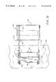
- FIG. 8 is a top view of a cushioning conversion machine and an alternate embodiment of a safety output chute including a labyrinth of rollers;
- FIG. 9 is a side elevational view of the cushioning conversion machine and safety output chute of FIG. 8;
- FIG. 10 is a front elevational view of the safety output chute of FIG. 8;
- FIG. 11 is a front elevational view of an alternate embodiment of a safety output chute including a movable shield
- FIG. 12 is a side elevational view of the safety output chute of FIG. 11;
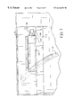
- FIG. 13 is a top view of a cushioning conversion machine employing an alternate embodiment of a safety output chute having an access cover;
- FIG. 14 is a side elevational view of the cushioning conversion machine and safety output chute of FIG. 13;
- FIGS. 15 and 16 are end views of the closure assembly in a closed position and an open position, respectively, for the safety output chute of FIG. 13;
- FIG. 17 is a front elevational view of a cushioning conversion machine in an alternate embodiment of a safety output chute having an access cover;
- FIG. 18 is a side elevational view of a cushioning conversion machine and safety output chute of FIG. 17;
- FIGS. 19 and 20 are views of a closure assembly with the access cover of the safety output chute closed and open, respectively;
- FIG. 21 is a cutaway elevation view of a safety output chute according to an alternate embodiment of the present invention.
- FIG. 22 is a cutaway top view of the safety output chute of FIG. 21;
- FIG. 23 is a close-up view of the flaps which constitute a part of the chute guide for a safety output chute
- FIG. 24 is a cutaway elevation view of the safety output chute of FIG. 21 with a cushioning product in the chute;
- FIG. 25 is a cutaway elevation view of the safety chute of FIG. 21 with the top tray elevated;
- FIG. 26 is a partial cross-sectional view of a safety output chute with a powered chute guard in a closed position
- FIG. 27 is a partial cross-sectional view of the safety output chute of FIG. 26 with the powered chute guard in an open position;
- FIG. 28 is an alternate embodiment of a safety output chute with a powered chute guard.
- FIG. 29 is a further alternate embodiment of a safety output chute with a powered chute guard.
- FIGS. 1 and 2 there is shown a cushioning conversion machine 10 for creating low density cushioning pads including a safety output chute 12 located at the downstream end 14 of the machine for providing the pads formed by the cushioning machine to an operator in a safe and effective manner.
- a safety output chute 12 located at the downstream end 14 of the machine for providing the pads formed by the cushioning machine to an operator in a safe and effective manner.
- the machine 10 includes a frame 16 to which are mounted a supply assembly 18 at the upstream end 20 of the frame for supplying stock material to be converted into a cushioning product, a conversion assembly 22 for converting the stock material into a continuous strip of cushioning product and a severing or cutting assembly 24 located generally between the conversion assembly and the safety output chute 12 at the downstream end 14 of the frame for severing the strip into cushioning pads of the desired length.
- a supply assembly 18 at the upstream end 20 of the frame for supplying stock material to be converted into a cushioning product
- a conversion assembly 22 for converting the stock material into a continuous strip of cushioning product
- a severing or cutting assembly 24 located generally between the conversion assembly and the safety output chute 12 at the downstream end 14 of the frame for severing the strip into cushioning pads of the desired length.
- the stock supply assembly 18 preferably includes a shaft or axle 28 for supporting a roll of sheet like stock material (not shown) and a number of rollers 30 for providing the stock material to the conversion assembly 22 .
- the stock material may consist of three superimposed webs of biodegradable, recyclable and reusable thirty-pound Kraft paper or the like rolled onto a hollow cylindrical tube.
- the conversion assembly 22 includes a forming assembly 32 , such as a cooperating three-dimensional wire former 34 and converging chute 36 as is shown in FIG. 1, and a feed assembly 38 including a pair of gears 40 for pulling the stock material through the forming assembly and feeding it through an outlet 42 to the severing or cutting assembly 24 and the safety chute 12 .
- the cutting assembly 24 is positioned adjacent the machine outlet 42 and may include one or more blades 44 or other means acting to sever the continuous strip of padding emerging from the outlet at the appropriate times.
- the cutting assembly 24 further includes a motor, air cylinder or solenoid 46 powering the blade 44 or other severing means through a shaft linkage assembly 50 .
- the area of the cutting operation is confined within an enclosure 52 mounted to an upstanding frame portion 54 including the machine outlet 42 and supported upon a frame extension 56 .
- Control of the cushioning conversion machine 10 in general and of the conversion assembly 22 and cutting assembly 24 in particular is preferably accomplished and coordinated through the use of a process controller (shown schematically at 51 ) as described more fully in copending U.S. patent application Ser. No. 08/279,149 which is incorporated herein in its entirety by this reference.
- the process controller 51 may communicate with the various elements and assemblies of the cushioning conversion machine 10 and peripheral components through a variety of conventional manners as would be understood by a person of skill in the art and such interconnections are thus not specifically illustrated in the drawing figures.
- a further description of the exemplary cushioning conversion machine 10 can be found in U.S. Pat. No. 4,699,609, which is incorporated herein in its entirety by this reference.
- the stock supply assembly 18 supplies the stock material to the forming assembly 32 .
- the frame structure 34 and conical chute 36 of the forming assembly 32 causes inward rolling of the lateral edges of the sheet-like stock material to form the lateral pillow-like portions of the continuous strip.
- the gears 40 of the feed assembly 38 pull the stock material downstream through the machine and also coin the central band of the continuous strip to form the coined strip.
- the cutting assembly 24 cuts the strip into pads of a desired length which then travel through the safety output chute 12 for collection by an operator.
- the safety output chute 12 is defined by housing 58 , generally rectangular in cross-section, open to receive a pad as it passes through the cutting assembly 24 and extending away from the cutting assembly in a downstream direction.
- the housing 58 is connected to the cutting assembly enclosure 52 and is supported by the frame extension 56 .
- Disposed within the housing 58 is a rotatable, multivaned assembly 60 formed of a number of vanes or blades 62 extending radially from a shaft 64 which traverses laterally the rectangular chute defined within the housing 58 .
- the shaft 64 is rotatably mounted to opposed sidewalls 66 of the housing 58 and is spaced from the bottom wall 68 in order to accommodate a pad 70 in a somewhat compressed condition between the vane 62 and bottom wall 68 .
- the vane 62 may be discontinuous axially along the shaft 64 in the form of discreet, spaced vane portion 72 , as shown in FIGS. 1 and 3, or as axially continuous vanes 74 , as is shown in FIG. 4 .
- a deflector panel 76 disposed within the housing 58 between the cutting assembly enclosure 52 and the vane assembly 60 is a deflector panel 76 extending from the upper, upstream portion of the housing downwardly and downstream to the space 77 (FIG. 4) between the vane assembly 60 and the bottom wall 68 to direct a pad between the bottom wall and the vane assembly.
- the deflector panel 76 is preferably mounted at its upper distal end to the top wall 78 by a hinge 80 and biased downwardly.
- a pad 70 emerging through the cutting assembly 24 and progressing through the safety output chute 12 will be directed under the vane assembly 62 by the deflector panel 76 , with the emanating pad thus turning the vane assembly as the pad is forced through the safety output chute. Consequently, the pad 70 can be directed through the safety output chute 12 to an operator while preventing the ingress of a hand past the vane assembly 62 .
- the pad is preferably compressed by the vane assembly 60 to a thickness such that access is limited toward the cutting assembly 24 , yet which still allows the pad to resiliently expand to substantially its original uncompressed size.
- the space 77 between the vane assembly 60 and the bottom wall 68 and the distance from the space to the cutting assembly 24 is preferably correlated such that access to the cutting assembly is limited by the combined effects of the narrow space 77 and its distance to the cutting assembly located upstream thereof.
- the shaft 64 may extend through an end wall 66 of the housing 58 for connection to a knob 82 , as is shown in FIG. 4, to permit the manual rotation of the vane assembly. This permits an operator to urge a pad 70 through the safety output chute 12 by rotation of the knob 82 . This is particularly advantageous where short sections of pad 70 are cut which may not extend through the output chute 12 through normal operation of the machine.
- the rotation of the vane assembly 62 may also be powered, such as is shown in FIG. 5, by extending the shaft 64 through the end wall 66 for connection to a sprocket 84 .
- the sprocket 84 is powered by a connection to the feed assembly 38 through the chain 86 .
- the chain 86 is enmeshed with sprocket 84 of the safety output chute 12 and sprocket 88 connected to the shaft 90 which drives the gears 40 of the feed assembly 38 . Consequently, when the conversion assembly 22 (FIG. 1) is producing a pad, as caused by the rotation of the gears 40 , the vane assembly 62 will also be rotating to urge the formed pad 70 (FIG. 2) through the safety output chute 12 to the operator.
- the output chute 100 includes a housing generally rectangular in cross-section which is connected to the cutting assembly enclosure 52 and supported by the frame extension 56 .
- the housing 102 defines a chute through which the pad formed by the cushioning conversion assembly 22 travels to an operator through an opening 104 .
- a sensor 106 Positioned near the opening 104 of the housing 102 , on a side wall thereof, is a sensor 106 for sensing the presence of an object within the chute defined by the housing.
- the sensor 106 preferably has sensing access within the housing 102 through a port or access opening 108 .
- the sensor 106 may be any one of a number of conventional sensors for sensing the presence of a foreign object, such as an infrared heat sensor or a capacitance sensor, and generating a signal responsive to the absence or presence of such a foreign object, such as a human appendage, for example a hand or fingers, in the housing 102 near the sensor.
- a foreign object such as a human appendage, for example a hand or fingers
- the sensor 106 is capable of discriminating between a pad and a foreign object such as the hand of the operator.
- An infrared sensor for example, could discriminate based on the heat as a hand or fingers would give off more heat than a pad.
- a capacitance sensor would discriminate based on the capacitance in the chute as the capacitance of a hand or fingers, for example, is different and distinguishable from the capacitance of a pad.
- the signal generated by the sensor 106 is provided through conventional means to the process controller which is programmed to prevent the operation of the cutting assembly 24 , such as through disabling the motor 46 of the cutting assembly 24 , when an object is in the housing 102 as sensed by the sensor 106 .
- the signal generated by the sensor 106 can be routed to a circuit dedicated to enabling or disabling the motor 46 powering the cutting assembly 24 .
- a labyrinth-like safety output chute 120 is shown in FIGS. 8 through 10 in conjunction with an exemplary cushioning conversion machine 122 .
- the cushioning conversion machine 122 is similar in design to that described above relative to FIG. 1, and is more comprehensively described in U.S. Pat. No. 5,322,477, for instance, which is incorporated herein in its entirety by this reference. (Reference numerals for assemblies of the cushioning conversion machine 122 which perform the same general functions as assemblies of the cushioning conversion machine 10 are designated by the same primed numbers.) It should be understood that the labyrinth output chute 120 may be equally employed with a cushioning conversion machine of the type depicted in FIG. 1 or a cushioning machine of a different type and that the safety output chutes 12 and 100 could be employed with the exemplary cushioning conversion machine 122 of FIG. 8 or other cushioning conversion machines not illustrated or discussed herein.
- the labyrinth safety output chute 120 acts to prevent the ingress of the hand of an operator to the blade 44 ′ of the cutting assembly 24 ′ by requiring the pad to progress through the chute along a path, such as a generally tortuous, non-linear or undulating path, that the hand and arm of an operator could not traverse.
- the labyrinth output chute 120 includes a housing 124 mounted to an enclosure 52 ′ substantially enclosing cutting operation of the cutting assembly 24 ′, the housing defining a chute for a pad to travel though from the cutting assembly to the point of an operator or other transitional or pad storage area.
- the housing 124 may be of a constant cross-section or the housing may diverge in the downstream direction as shown in FIG. 9 .
- Each guide roller 126 , 128 and 130 includes a shaft 132 extending between and rotatably mounted to opposite side walls 134 of the housing 124 such that the axis of rotation of the rollers will preferably be parallel to a plane which passes laterally through the pad as it approaches the rollers from the cutting assembly 24 ′. While not so limited, the guide rollers 126 , 128 and 130 are preferably of the same length and extend substantially across the lateral width of the housing 124 between side walls 134 .
- the open space between the outer peripheries of adjacent guide rollers 126 , 128 and 130 is determined so as to permit a pad to fit therebetween with minimal compression of the pad.
- the vertical distance between the centerlines of the guide rollers is so chosen that the pad is forced to follow an undulating or somewhat inclined “S” shape path and to bend or undulate in a substantially vertical direction to follow the path.
- the guide rollers 126 , 128 and 130 are shown as being spaced substantially the same distance from each other, the guide rollers can be offset so that the distance between adjacent rollers is not the same.
- the shafts 132 could be independently spring biased with the travel for each roller being limited such that the rollers continue to overlap so as to maintain a labyrinth function.
- the housing 124 could also be provided with lateral guides in order to direct the travel of the pad between the rollers 126 , 128 and 130 .
- the rotation of the guide rollers 126 , 128 and 130 could be effected passively, by movement of the pad through the labyrinth, or actively, either by a separate motor 136 driving one or more of the guide rollers, or by coupling one or more of the guide rollers to the feed assembly 38 ′ much in the same way as the vane assembly 62 is coupled to the feed assembly 38 in the manner shown in FIG. 5 .
- each guide roller 126 , 128 and 130 preferably allows sliding contact with the pad in an application where the rollers are not powered separate from the movement of a pad therebetween, and a somewhat gripping contact with the pad when the rollers are separately powered to urge the pad through the labyrinth output chute 120 .
- the construction of the rollers 126 , 128 and 130 may be chosen a variety of materials based on the application. Additionally, if desired, the rollers could serve a dual purpose by also perforating the pad or making a marking on the pad so as to facilitate use of a pad length measuring device in conjunction with the labyrinth safety output chute 120 .
- a pad (not shown) formed by the conversion assembly 22 ′ passes through the cutting assembly 24 ′ to the labyrinth safety output chute 120 where its is fed above the first guide roller 126 rotating clockwise, below the second guide roller 128 rotating counterclockwise and above the last guide roller 130 rotating clockwise and then emanates from the chute for use by the operator.
- FIGS. 11 and 12 A further embodiment of an safety output chute 150 for use with a cushioning conversion machine, such as the machine 10 illustrated in FIG. 1, is shown in FIGS. 11 and 12.
- the safety output chute 150 includes a housing 152 of the same basic design as the housing 102 shown in FIGS. 6 and 7 and described above. Disposed within the chute defined within the housing 152 is a shield 154 which is connected at its upstream end 156 to the upper, upstream portion of the housing by a hinge 157 .
- the shield 154 extends downwardly in the downstream direction to define a space 158 between the distal end 160 of the shield 154 and the bottom wall 162 of the housing 152 through which the pad 70 traverses.
- a lever 166 Extending from the shield 154 through a side wall 164 of the housing 152 in order to be operative outside of the housing 152 is a lever 166 which moves with shield 154 within the housing.
- the lever 166 is connected to a piston portion 168 of a solenoid 170 which is in turn mounted to the outer face of the side wall 164 of the housing 152 . Operation of the solenoid 170 thus moves the lever 166 and likewise the shield 154 within the housing 152 .
- a limit switch 172 mounted to the outer face of the side wall 164 of the housing 152 below the lever 166 generates a signal indicative of whether the lever, and thus the shield 154 , are in their lowermost or closed condition, wherein the shield slightly compresses the pad 70 or senses the presence of a hand in the chute because the chute is in a relatively raised position.
- the solenoid 170 is controlled by the previously noted process controller 51 which also receives the signals generated by the limit switch 172 .
- the lever 166 , the solenoid 170 and the limit switch 172 are contained within an enclosure 174 .
- the piston portion 168 of the solenoid 170 is in a retracted state thus drawing the lever 166 and shield 154 to a relatively upper or open state away from the bottom wall 162 thus increasing the space 158 through which the pad may traverse within the chute.
- the process controller 51 causes the solenoid 170 to extend the piston portion 168 forcing the lever 166 and the shield 154 relatively downwardly to narrow the space 158 and compress the pad 70 therein.
- the force exerted by shield 154 on the pad is preferably adequate to compress the pad as desired, but limited so as not to present a hazard to a hand below the shield.
- the limit switch 172 may act as a true switch in series with the cut motor or solenoid 46 preventing its operation when the limit switch is in its open position.
- the safety output chute 200 is connected to a cushioning conversion machine 10 downstream of the cutting assembly (not shown) adjacent an output passage 202 (FIG. 15 ).
- the safety output chute 200 and cushioning conversion machine 10 function cooperatively in a manner similar to a vending machine.
- the safety output chute 200 includes a cover 204 mounted to a chute body 206 by means of a hinge 208 .
- the cover 204 includes a transparent insert 210 which permits the operator to see a pad within the safety output chute 200 .
- the safety output chute 200 may also, but not necessarily, include an assembly 212 which permits a pad to travel from the machine to the safety output chute 200 when the cover 204 is in its closed position, as shown in FIG. 15, but which closes off access to the machine and cutting assembly (not shown) through the opening 202 when the cover is in an open position, as shown in FIG. 16 .
- the closure assembly 212 includes a sliding door element 214 which is operable to slide vertically within guides 216 spaced at opposite lateral sides of the chute 200 .
- the sliding door 214 includes a vertical projection 218 including a wheel 220 at an end distal from the main portion of the door for contact with the inside surface 222 of the cover 204 .
- the sliding door 214 is biased vertically upwardly by a pair of springs 224 . Consequently, when the cover 204 of the safety output chute 200 is in a closed position, as shown in FIG. 15, the wheel 220 is forced downwardly causing the sliding door to slide downwardly by compressing the springs 224 and permitting access via the opening 202 to the cutting assembly for receipt of a pad.
- the springs 224 urge the sliding door 214 in an upward direction to substantially cover the passage or opening 202 and permit access to the cutting assembly.
- the safety output chute 200 may be provided with sensors or limit switches (not shown) to sense whether the cover 204 is in an open or closed position and to disable or enable a cutting operation accordingly.
- the end of the safety output chute 200 remote from the machine 10 can be open or closed.
- An open end permits pads of unlimited lengths to be produced, but in such an instance the chute should be of sufficient length to inhibit physical access by the operator to the cutting assembly 24 from the open end.
- FIGS. 17 through 20 A further embodiment of a safety output chute 230 configured with a cushioning conversion machine 10 to operate analogous to a vending machine is shown in FIGS. 17 through 20.
- the machine 232 is preferably supported on a frame 234 in an upright, vertical position.
- the frame may also include casters 236 to facilitate movement of the cushioning conversion machine to an appropriate location where strip material is desired at a given time.
- the cushioning conversion machine 232 is preferably oriented vertically with the stock supply assembly 18 located relatively near the floor and the machine output 238 facing upwardly.
- the safety output chute 230 is mounted in a vertical orientation adjacent the cushioning conversion machine 232 by a number of mounting brackets 240 .
- a pad is transferred from the cushioning conversion machine 232 to the safety output chute 230 through a 180° arcuate passage 242 located above the cushioning conversion machine and the output chute.
- the safety output chute 230 preferably includes a cover 244 mounted to the chute body 246 by a hinge 248 .
- the chute cover 244 preferably also includes a transparent window insert 250 to permit the operator to visually determine whether a pad has been deposited into the safety output chute 230 .
- the safety output chute 230 is provided with a sensor or limit switch which permits operation of the cushioning conversion machine 232 only when the door 244 is shut and may either alternatively or with the limit switch include a means for locking the cover 244 in a closed condition when the cushioning conversion machine is in operation.
- the end of the output chute 230 remote from the cushioning conversion machine 232 may be open or closed. However, when the end of the output chute 230 is open, as discussed above, the length of the chute should be sufficiently long to inhibit physical access by the operator to the cutting assembly 24 from the open end of the chute.
- a machine output closure assembly 252 may also be provided to close the machine outlet 202 when the cover 244 is in an open position, as shown in FIG. 20 and to open access from the machine output to the arcuate passage 242 when the cover is closed, as shown in FIG. 19 .
- the closure mechanism 252 is configured similar to the closure mechanism 212 illustrated in FIGS. 15 and 16.
- the closure mechanism 252 includes a sliding door 254 which alternatively opens the machine outlet 202 when in a retracted position and closes access to the machine output when in its unretracted position when the door 244 of the safety machine output chute 230 is open.
- the sliding door 254 slides horizontally within the slides 256 and is biased towards a closed position by springs 258 .
- FIGS. 21 through 25 A partially retractable safety output chute 300 is illustrated in FIGS. 21 through 25. As seen in the cross-sections of FIG. 21 and 22, the chute 300 is formed by confronting lower and inverted upper tray shape elements 302 and 304 .
- the lower tray 302 is rigidly connected to the cutting assembly enclosure 52 at an end 306 while the upper tray 304 is hingedly connected to the cutting assembly enclosure by the hinge 308 to pivot upwardly away from the lower tray and provide access to within the output chute 300 .
- the lower and upper trays 302 , 304 cooperatively diverge away from the cutting assembly enclosure 52 to form the chute output 310 .
- a deflector plate 312 guides a formed pad 314 (FIG. 24) from the cutting assembly enclosure 52 through the output chute 300 .
- a chute guard 316 Disposed within the output chute 300 hingedly connected to the upper tray 304 , near the upper wall 315 , is a chute guard 316 .
- the chute guard 316 preferably extends from the upper tray 304 sufficiently that when the chute 300 is closed and a pad is not present in the chute, the distal end of the chute guard contacts the lower tray 302 and cannot be freely deflected toward the cutting assembly.
- the chute guard 316 is preferably composed of two offset curtains or rows 318 , 320 of several independent flaps 322 , 324 , respectively, each rotatably connected to a rod 326 extending between side walls 328 of the upper tray 304 to effect the hinged connection between the upper tray 304 and the chute guard.
- the flaps 322 of row 318 are offset with the flaps 324 of row 320 by a distance of one-half of the axial length of a flap so that ingress from the chute opening 310 to the cutting assembly enclosure 52 requires that at least one flap of each row be outwardly displaced.
- a secondary chute guard 330 is hingedly connected to the lower tray 302 and biased, such as through spring 332 , away from the bottom wall 334 of the lower tray to protrude into chute area.
- the secondary chute guard 330 is angled in its extended biased condition toward the chute opening 310 so that the secondary chute guard can be pressed toward the bottom wall 334 of the lower tray to accommodate a pad through the chute as shown in FIG. 24 .
- the secondary chute guard 330 cooperates with the chute guard 316 to further inhibit access to the cutting assembly enclosure 52 from the chute output 310 .
- the chute guard 316 When a pad is not present in the output chute 300 as is the condition shown in FIG. 21, the chute guard 316 extends downwardly away from the upper tray 304 , such as through the force of gravity, preferably to contact the bottom wall 334 of the lower tray 302 .
- the secondary chute guard 330 is biased away from the bottom wall 334 of the lower tray 302 to protrude into confines of the output chute.
- the chute guard 316 and secondary chute guard 330 thus require for an object to progress from the chute output 310 to the cutting assembly enclosure 52 that the object pass below the chute guard 316 and above the secondary chute guard 330 to effectively inhibit access to the cutting assembly 24 within the cutting assembly enclosure 52 .
- the upper tray 304 may be retracted by lifting the output end of the upper tray around the hinge 308 , as shown in FIG. 25, to provide access within the interior of the output chute 300 .
- the chute guard 316 through the force of gravity, will rotate downwardly away from the upper wall 315 of the upper tray 304 to protrude substantially across the opening 340 between the cutting assembly enclosure 52 and the output chute 300 to at least partially restrict, with the secondary chute guard 330 , access to the cutting assembly 24 .
- the lower and upper trays 302 and 304 are preferably provided with a keyed safety interlock switch embodied through the key 342 protruding from the upper tray for capture by a receptacle element 344 in the lower tray.
- the keyed interlock switch provides an indication to the cushioning conversion machine of whether the output chute is open or closed to be used in a logic circuit or by the machine controller 51 (FIG. 1) to prevent engagement of the cutting assembly 24 when the upper tray is not in a closed position.
- the powered chute guard assembly includes a chute guard or shield 352 disposed within a divergent output chute 354 and an actuating mechanism 356 , such as a linear motor or a pneumatic, hydraulic or electric solenoid powering a rod 358 in engagement with the chute guard 352 through a rotatable connection 359 .
- the chute guard 352 is hingedly connected at its interior end, through a hinge 360 , to the deflector plate 312 secured to the cutting assembly enclosure 52 to allow it to move between an open position shown in FIG. 26 and a closed position shown in FIG. 27 .
- the pad 361 may progress through the output chute 354 relatively unhindered by the chute guard 352 , such as when the pad 361 is being produced.
- the chute guard 352 compresses the pad 361 somewhat to prevent ingress of an object through the output chute 354 from the output end 362 , such as when a pad is being severed by the cutting assembly 24 .
- the solenoid 356 is mounted to a mounted plate 364 spaced from the cutting assembly enclosure 52 by spacers 366 so that the rod 358 extending from the solenoid 356 connects to the chute guard 352 at a suitable distance from the hinge 360 .
- a coiled compression spring 368 coaxial with the rod 358 and extending between a shoulder 370 of the rotatable connector 359 and the lower surface of a flange 372 biases the rod 358 and chute guard 352 downwardly to a closed position, as shown in FIG. 27 .
- the spring 368 could be located elsewhere to perform the same function, such as embodied into the solenoid 356 .
- the force of the spring 368 is preferably sufficient to compress the pad 361 to a thickness that would be less than that of a hand, while not damaging the pad, for example approximately 3 ⁇ 4 of an inch.
- the spring force should also not be so strong as to cause harm to a person's hand or fingers if they were to be beneath the chute guard 352 upon being moved towards its closed position.
- the cutting assembly can execute a cutting cycle only when the chute guard 352 is in this closed position.
- the position of the chute guard 352 is detected by a contact sensor 374 mounted to the flange 372 and having a contact 376 for contact with a finger 378 secured to the rod 358 to move axially with the rod.
- the sensor 374 generates a signal indicative of whether or not the contact is depressed by the finger 378 which is provided to a logic circuit or the machine controller 51 of the cushioning conversion machine for use in determining whether the machine may sever the pad 361 in the output chute.
- the solenoid While a pad is being produced the solenoid is energized, causing the rod 358 to retract, compressing the spring 368 and pulling the chute guard 352 upwardly into the open position, shown in FIG. 26, to allow the pad 361 to progress through the chute 354 as it is being formed.
- the solenoid is de-energized and the force of the spring 368 causes the rod 358 and attached chute guard 352 to move downwardly into the output chute, as shown in FIG. 27 .
- the finger 378 With the chute guard fully lowered and the pad compressed, the finger 378 will depress the contact 376 and the sensor 374 will generate a signal to the cushioning conversion machine allowing a cut operation to take place.
- the finger 378 will fail to depress adequately the contact 376 and as the sensor 374 will not generate the chute closed signal, thus preventing a cutting operation from being executed.
- a coiled extension spring can be secured to the flange 372 and shoulder 370 and can bias the chute guard 352 in its open position.
- the solenoid 356 would not be energized during a pad forming and feeding operation, but would be energized to overcome the spring bias and cause the rod 358 to extend downwardly on being energized.
- the solenoid 356 is energized and, if the chute guard 352 can be depressed sufficiently to reach its closed position, the sensor 374 will sense the finger 378 depressing the contact 376 and the cutting operation will be permitted.
- solenoid 356 and rod 358 could be oriented horizontally, with the horizontal motion of the rod translated into hinged movement of the chute guard 352 through conventional methods.
- an output chute guard 380 as shown in FIG. 28 so that a relatively smaller area of the chute guard depresses a smaller area of the pad 361 (FIG. 27 ), preferably outside of the output chute 354 ′, to reduce the amount of force necessary to compress the pad sufficiently to prevent ingress of a foreign object into the chute during cutting operation.
- the design of the output chute 354 ′, the solenoid 356 ′, rod 358 ′ and sensor may be the same or similar to the like numbered components described above relative to FIGS. 26 and 27.
- the pad With the distal portion of the chute guard 380 positioned outside of the output chute 354 ′, the pad is caused to curve downwardly about the lower distal edge 381 of the output chute when the chute guard is in its lowered or closed position 380 a, substantially preventing ingress into the chute from below the pad.
- a output chute deflector 382 positioned over the output 384 of the output chute inhibits ingress into the chute above the pad. Control and actuation of the chute guard 380 between its closed 380 a and open 380 b positions can be accomplished similarly to that described immediately above relative to FIGS. 26 and 27, with the actuator mechanism and spring being adapted as discussed above to provide a biased closed or biased open operation.
- FIG. 29 there is shown an embodiment of an output chute 354 ′′ with a chute guard 380 ′′ similar to that shown in FIG. 28, with the exception that the chute guard 380 ′′ is adapted to contact the pad 361 within the output chute.
- the output chute guard 380 ′′ contacts the pad within the output chute 354 ′′ over a small area of contact such as along a line transverse to the direction to the movement of the pad through the output chute to reduce the amount of force required to compress the pad.
- the chute guard 380 ′′ may thus be in the form of a generally flat plate which extends downwardly abruptly near its distal end 390 to contact the pad 361 .
- the chute guard 380 ′′ may operate between an open position 380 a ′′ and a closed position 380 b ′′ similar to the chute guard 380 discussed above.
Abstract
Description
Claims (13)
Priority Applications (1)
| Application Number | Priority Date | Filing Date | Title |
|---|---|---|---|
| US09/217,696 US6416451B1 (en) | 1996-06-28 | 1998-12-21 | Output chute for cushioning conversion machine |
Applications Claiming Priority (3)
| Application Number | Priority Date | Filing Date | Title |
|---|---|---|---|
| US67330796A | 1996-06-28 | 1996-06-28 | |
| PCT/US1997/011515 WO1998000288A1 (en) | 1996-06-28 | 1997-06-30 | Cushioning conversion machine |
| US09/217,696 US6416451B1 (en) | 1996-06-28 | 1998-12-21 | Output chute for cushioning conversion machine |
Related Parent Applications (1)
| Application Number | Title | Priority Date | Filing Date |
|---|---|---|---|
| PCT/US1997/011515 Continuation WO1998000288A1 (en) | 1996-06-28 | 1997-06-30 | Cushioning conversion machine |
Publications (1)
| Publication Number | Publication Date |
|---|---|
| US6416451B1 true US6416451B1 (en) | 2002-07-09 |
Family
ID=24702114
Family Applications (1)
| Application Number | Title | Priority Date | Filing Date |
|---|---|---|---|
| US09/217,696 Expired - Lifetime US6416451B1 (en) | 1996-06-28 | 1998-12-21 | Output chute for cushioning conversion machine |
Country Status (6)
| Country | Link |
|---|---|
| US (1) | US6416451B1 (en) |
| EP (2) | EP0958135A1 (en) |
| AU (1) | AU3590297A (en) |
| CA (1) | CA2259266A1 (en) |
| DE (2) | DE03078129T1 (en) |
| WO (1) | WO1998000288A1 (en) |
Cited By (16)
| Publication number | Priority date | Publication date | Assignee | Title |
|---|---|---|---|---|
| US6632165B1 (en) * | 2000-11-01 | 2003-10-14 | Guy Letourneau | Paper conversion dispenser machine |
| US6672037B2 (en) * | 2000-12-12 | 2004-01-06 | Automated Packaging Systems, Inc. | Apparatus and process for dispensing dunnage |
| US6676589B2 (en) * | 2000-06-09 | 2004-01-13 | Ranpak Corp. | Dunnage conversion machine with translating grippers, and method and product |
| US20050181924A1 (en) * | 2003-07-07 | 2005-08-18 | Raimond Demers | Cutterless dunnage converter and method |
| WO2006052980A3 (en) * | 2004-11-05 | 2006-08-17 | Ranpak Corp | Automated dunnage filling system and method |
| US20080200325A1 (en) * | 2005-02-22 | 2008-08-21 | Ranpak Corp. | Dunnage Conversion Machine And Output Chute Guard |
| US20110053748A1 (en) * | 2009-08-28 | 2011-03-03 | Pregis Innovative Packaging, Inc. | Reconfigurable dunnage handler |
| US20140113794A1 (en) * | 2012-10-12 | 2014-04-24 | Storopack Hans Reichenecker Gmbh | Device for making a paper pad product |
| US20150352802A1 (en) * | 2014-06-09 | 2015-12-10 | Storopack, Inc. | Protective packaging work station |
| US20160207274A1 (en) * | 2013-09-23 | 2016-07-21 | Sprick Gmbh Bielefelder Papier-Und Wellpappenweke & Co. | Perforation Tool for a Device for the Production by Machine of a Filling Material Product and a Device for the Production by Machine of a Filling Material Product |
| US20180079161A1 (en) * | 2015-02-26 | 2018-03-22 | Ranpak Corporation | Dunnage conversion system and method for expanding pre-slit sheet stock material |
| WO2019020633A1 (en) * | 2017-07-25 | 2019-01-31 | Storopack Hans Reichenecker Gmbh | Device for dispensing a padding material for packaging purposes |
| USD874529S1 (en) * | 2017-09-13 | 2020-02-04 | Ranpak Corp. | Dunnage conversion machine |
| USD889522S1 (en) * | 2018-07-16 | 2020-07-07 | Nuevopak Technology Company Limited | Cushioning material machine |
| US20210299990A1 (en) * | 2017-05-11 | 2021-09-30 | Pregis Innovative Packaging Llc | Dunnage apparatus carton filler |
| US11491756B2 (en) | 2016-10-11 | 2022-11-08 | Sealed Air Corporation (Us) | Machine and method for producing void fill packaging material |
Families Citing this family (9)
| Publication number | Priority date | Publication date | Assignee | Title |
|---|---|---|---|---|
| US5739333A (en) * | 1995-05-16 | 1998-04-14 | Tanabe Seiyaku Co., Ltd. | Sulfonamide derivative and process for preparing the same |
| EP1044794A3 (en) * | 1998-12-09 | 2003-07-23 | Ranpak Corp. | Cushioning conversion machine and method with plural constant entry rollers and moving blade shutter |
| FR2798920B1 (en) * | 1999-09-27 | 2001-12-28 | Naturembal Sa | GUIDING DEVICE PROVIDED AT THE OUTPUT OF A MACHINE FOR MANUFACTURING UPHOLSTERY IN PAPER MATERIAL |
| SG186497A1 (en) * | 2002-04-22 | 2013-01-30 | Ranpak Corp | Dunnage converter system |
| DE102008039617A1 (en) * | 2008-08-25 | 2010-03-04 | Sprick Gmbh Bielefelder Papier- Und Wellpappenwerke & Co. | Packaging material reservoir for a device for providing packaging material |
| US8376114B2 (en) * | 2009-09-14 | 2013-02-19 | Sealed Air Corporation | Dunnage discharge safety chute |
| DE102014016874A1 (en) * | 2014-11-14 | 2016-05-19 | Sprick Gmbh Bielefelder Papier- Und Wellpappenwerke & Co. | Device for machining a filler product |
| DE102018009679A1 (en) | 2018-12-11 | 2020-06-18 | Sprick GmbH Papier- und Wellpappenwerke & Co. | Multi-drive device for manufacturing a packaging material product from a fiber raw material, method for manufacturing a packaging material product and method for removing packaging material blockages |
| DE102018009678A1 (en) | 2018-12-11 | 2020-06-18 | Sprick Gmbh Bielefelder Papier- Und Wellpappenwerke & Co. | Guillotine cutting device for producing a packaging material product from a fiber raw material and method for producing a packaging material product |
Citations (55)
| Publication number | Priority date | Publication date | Assignee | Title |
|---|---|---|---|---|
| US3155314A (en) * | 1963-05-08 | 1964-11-03 | Peter A Kreider | Trash disposal apparatus |
| US3641841A (en) * | 1969-03-24 | 1972-02-15 | Masahiro Komori | Safety gate for press |
| US3888148A (en) | 1973-09-14 | 1975-06-10 | Bernard Weissman | Saw blade guard |
| US3977668A (en) | 1975-09-26 | 1976-08-31 | Pitney-Bowes, Inc. | Dual purpose sheet material feeding and safety apparatus |
| US4026198A (en) * | 1975-05-01 | 1977-05-31 | Ranpak Corporation | Cushioning dunnage mechanism, transfer cart therefor, and method |
| US4040336A (en) | 1976-07-26 | 1977-08-09 | The Torrington Company Limited | Cutting or grinding tool protecting guard |
| US4074602A (en) | 1976-12-30 | 1978-02-21 | C. O. Porter Machinery Company | Defecting saw |
| US4085303A (en) | 1976-03-08 | 1978-04-18 | Ametek, Inc. | Safety double protection device for machines having plural circuit breaker assemblies associated with doffer roller and hand guard |
| US4088856A (en) | 1976-07-01 | 1978-05-09 | Acrometal Products, Inc. | Perimeter safety switch mounted to support disposed remote from machine body |
| US4123959A (en) | 1976-08-27 | 1978-11-07 | Maja-Maschinenfabrik Hermann Schill Gmbh | Slicing machine for bacon or the like |
| US4306439A (en) | 1980-01-07 | 1981-12-22 | Modine Manufacturing Company | Safety device |
| US4318324A (en) | 1980-09-22 | 1982-03-09 | Rock Mill, Inc. | Cutting machine with guard for cutting blade |
| US4424741A (en) | 1981-11-18 | 1984-01-10 | Moldestad Jon P | Press machine safety apparatus |
| US4462287A (en) | 1982-12-02 | 1984-07-31 | Crown Zellerbach Corporation | Apparatus for culling cant ends |
| US4524657A (en) | 1983-06-10 | 1985-06-25 | Power Access Corporation | Automatic wire cutting machine |
| US4528488A (en) | 1981-10-07 | 1985-07-09 | Rolf Susemihl | Warning device using power tool residual kinetic energy |
| US4536144A (en) | 1982-09-17 | 1985-08-20 | Karl Hehl | Reversing mechanism for safety gate of injection molding machine |
| US4555105A (en) | 1983-04-15 | 1985-11-26 | At&T Technologies, Inc. | Method and apparatus utilizing magnetically coupled rollers to feed sheets |
| US4554806A (en) | 1984-02-16 | 1985-11-26 | Hewins Doris J | Motor driven mini-wringer |
| DE3421216A1 (en) | 1984-06-07 | 1985-12-12 | Peter 6501 Sörgenloch Heinrichs | Motor-driven, moving glass shield for workplace protection on conveyor-belt operating points, pressing, stamping and welding installations, or the like |
| US4699609A (en) | 1986-02-25 | 1987-10-13 | Ranpak Corp. | Electric cutter mechanism for dunnage converter |
| US4699031A (en) | 1986-02-20 | 1987-10-13 | Ametek, Inc. | Method and apparatus for automatically cutting a web of foam material into sheets and for dispensing the cut sheets |
| US4761901A (en) | 1986-10-22 | 1988-08-09 | Henry Szafarz | Safety guard for a power tool discharge chute |
| US4787544A (en) | 1986-05-05 | 1988-11-29 | Jones Charles R | Dancer roller |
| FR2624830A1 (en) | 1987-12-22 | 1989-06-23 | Monarch Marking Systems Inc | LABEL STACK AND STACKING METHOD THEREOF |
| US4968291A (en) | 1989-05-03 | 1990-11-06 | Ranpak Corp. | Stitching gear assembly having perforating projections thereon, for use in converter adapted to produce pad-like cushioning material, and method |
| US4976600A (en) | 1988-06-21 | 1990-12-11 | Apv Baker Pty Ltd. | Bread molders |
| WO1991006694A1 (en) | 1989-11-02 | 1991-05-16 | Eco-Pack Industries, Inc. | Resilient packing product |
| US5044270A (en) | 1988-10-18 | 1991-09-03 | H S M - Pressen Gmbh | Shredder and compactor with protective guard |
| US5076555A (en) | 1990-07-25 | 1991-12-31 | Bunch Jr Earnest B | Apparatus for partially severing strip of paper along lines offset from lines of weakening in the paper |
| US5088972A (en) * | 1989-11-02 | 1992-02-18 | Eco-Pack Industries, Inc. | Folding and crimping apparatus |
| US5123889A (en) | 1990-10-05 | 1992-06-23 | Ranpak Corporation | Downsized cushioning dunnage conversion machine and cutting assemblies for use on such a machine |
| EP0523382A2 (en) | 1991-06-17 | 1993-01-20 | Sealed Air Corporation | Apparatus for fabricating dunnage material from continuous web material |
| US5241885A (en) | 1991-10-11 | 1993-09-07 | Fritz Kuchler | Slicing machine with accident protection |
| US5292238A (en) | 1992-05-20 | 1994-03-08 | Mama Irene's Specialty Candies, Inc. | Apparatus for making cotton candy and preparing it for packaging |
| US5322477A (en) | 1990-10-05 | 1994-06-21 | Ranpak Corp. | Downsized cushioning dunnage conversion machine and packaging systems employing the same |
| EP0650827A2 (en) | 1993-10-27 | 1995-05-03 | Mercamer Oy | Package padding material and apparatus for forming package padding material |
| WO1995013914A1 (en) | 1993-11-19 | 1995-05-26 | Ranpak Corp. | A packaging program |
| WO1995014569A1 (en) | 1993-11-23 | 1995-06-01 | Ranpak Corp. | Dispensing table for a cushioning conversion machine |
| US5427020A (en) | 1993-06-05 | 1995-06-27 | Sulzer Papertec Krefeld Gmbh | Finger-protection device for a roller gap |
| US5435218A (en) | 1992-08-03 | 1995-07-25 | Comas S.P.A. | Slicing machine |
| US5442983A (en) | 1993-09-30 | 1995-08-22 | D'angelo; Joseph J. | All-electric web feeding, cutting and sheet dispensing machine |
| WO1995028276A1 (en) | 1994-04-15 | 1995-10-26 | Ranpak Corp. | A cushion producing machine |
| DE4424381A1 (en) | 1994-07-13 | 1996-01-18 | Franz Hellmut | Machine for manufacturing of paper packing material |
| DE19512716A1 (en) | 1994-04-13 | 1996-01-25 | Gerhard Dallinger | Packaging material based on multi-ply sheet material |
| WO1996003273A1 (en) | 1994-07-22 | 1996-02-08 | Ranpak Corp. | Cushioning conversion machine and method |
| US5538490A (en) | 1993-02-15 | 1996-07-23 | Fujitsu Limited | Safety bar mechanism and sheet processing device having a safety bar mechanism |
| US5542232A (en) | 1993-11-19 | 1996-08-06 | Ranpak Corp. | Transitional slide for use with a cushion-creating machine |
| WO1996035576A1 (en) | 1995-05-09 | 1996-11-14 | Ranpak Corp. | Dispensing table and guide system for a cushioning conversion machine |
| WO1997002183A1 (en) | 1995-07-05 | 1997-01-23 | Ranpak Corp. | Packaging system including cushoning conversion machine |
| EP0779148A1 (en) | 1995-12-15 | 1997-06-18 | Tokuji Watanabe | Method and apparatus for manufacturing paper cushioning members |
| US5709642A (en) | 1994-07-22 | 1998-01-20 | Ranpak Corp. | Cushioning conversion machine and method |
| US5785639A (en) | 1994-04-01 | 1998-07-28 | Ranpak Corp. | Cushioning conversion machine for making a cushioning product having a shell and stuffing formed from separate plies |
| US5806759A (en) * | 1995-02-21 | 1998-09-15 | Axisa; Anthony | Recycling and waste disposal apparatus |
| US5823936A (en) | 1996-02-08 | 1998-10-20 | Ranpak Corp. | Loading assembly and method for cushioning conversion machine |
-
1997
- 1997-06-30 AU AU35902/97A patent/AU3590297A/en not_active Abandoned
- 1997-06-30 EP EP97932440A patent/EP0958135A1/en not_active Withdrawn
- 1997-06-30 DE DE03078129T patent/DE03078129T1/en active Pending
- 1997-06-30 EP EP03078129A patent/EP1393888B1/en not_active Expired - Lifetime
- 1997-06-30 CA CA002259266A patent/CA2259266A1/en not_active Abandoned
- 1997-06-30 DE DE69735564T patent/DE69735564T2/en not_active Expired - Fee Related
- 1997-06-30 WO PCT/US1997/011515 patent/WO1998000288A1/en not_active Application Discontinuation
-
1998
- 1998-12-21 US US09/217,696 patent/US6416451B1/en not_active Expired - Lifetime
Patent Citations (57)
| Publication number | Priority date | Publication date | Assignee | Title |
|---|---|---|---|---|
| US3155314A (en) * | 1963-05-08 | 1964-11-03 | Peter A Kreider | Trash disposal apparatus |
| US3641841A (en) * | 1969-03-24 | 1972-02-15 | Masahiro Komori | Safety gate for press |
| US3888148A (en) | 1973-09-14 | 1975-06-10 | Bernard Weissman | Saw blade guard |
| US4026198A (en) * | 1975-05-01 | 1977-05-31 | Ranpak Corporation | Cushioning dunnage mechanism, transfer cart therefor, and method |
| US3977668A (en) | 1975-09-26 | 1976-08-31 | Pitney-Bowes, Inc. | Dual purpose sheet material feeding and safety apparatus |
| US4085303A (en) | 1976-03-08 | 1978-04-18 | Ametek, Inc. | Safety double protection device for machines having plural circuit breaker assemblies associated with doffer roller and hand guard |
| US4088856A (en) | 1976-07-01 | 1978-05-09 | Acrometal Products, Inc. | Perimeter safety switch mounted to support disposed remote from machine body |
| US4040336A (en) | 1976-07-26 | 1977-08-09 | The Torrington Company Limited | Cutting or grinding tool protecting guard |
| US4123959A (en) | 1976-08-27 | 1978-11-07 | Maja-Maschinenfabrik Hermann Schill Gmbh | Slicing machine for bacon or the like |
| US4074602A (en) | 1976-12-30 | 1978-02-21 | C. O. Porter Machinery Company | Defecting saw |
| US4306439A (en) | 1980-01-07 | 1981-12-22 | Modine Manufacturing Company | Safety device |
| US4318324A (en) | 1980-09-22 | 1982-03-09 | Rock Mill, Inc. | Cutting machine with guard for cutting blade |
| US4528488A (en) | 1981-10-07 | 1985-07-09 | Rolf Susemihl | Warning device using power tool residual kinetic energy |
| US4424741A (en) | 1981-11-18 | 1984-01-10 | Moldestad Jon P | Press machine safety apparatus |
| US4536144A (en) | 1982-09-17 | 1985-08-20 | Karl Hehl | Reversing mechanism for safety gate of injection molding machine |
| US4462287A (en) | 1982-12-02 | 1984-07-31 | Crown Zellerbach Corporation | Apparatus for culling cant ends |
| US4555105A (en) | 1983-04-15 | 1985-11-26 | At&T Technologies, Inc. | Method and apparatus utilizing magnetically coupled rollers to feed sheets |
| US4524657A (en) | 1983-06-10 | 1985-06-25 | Power Access Corporation | Automatic wire cutting machine |
| US4554806A (en) | 1984-02-16 | 1985-11-26 | Hewins Doris J | Motor driven mini-wringer |
| DE3421216A1 (en) | 1984-06-07 | 1985-12-12 | Peter 6501 Sörgenloch Heinrichs | Motor-driven, moving glass shield for workplace protection on conveyor-belt operating points, pressing, stamping and welding installations, or the like |
| US4699031A (en) | 1986-02-20 | 1987-10-13 | Ametek, Inc. | Method and apparatus for automatically cutting a web of foam material into sheets and for dispensing the cut sheets |
| US4699609A (en) | 1986-02-25 | 1987-10-13 | Ranpak Corp. | Electric cutter mechanism for dunnage converter |
| US4787544A (en) | 1986-05-05 | 1988-11-29 | Jones Charles R | Dancer roller |
| US4761901A (en) | 1986-10-22 | 1988-08-09 | Henry Szafarz | Safety guard for a power tool discharge chute |
| FR2624830A1 (en) | 1987-12-22 | 1989-06-23 | Monarch Marking Systems Inc | LABEL STACK AND STACKING METHOD THEREOF |
| US4976600A (en) | 1988-06-21 | 1990-12-11 | Apv Baker Pty Ltd. | Bread molders |
| US5044270A (en) | 1988-10-18 | 1991-09-03 | H S M - Pressen Gmbh | Shredder and compactor with protective guard |
| US4968291A (en) | 1989-05-03 | 1990-11-06 | Ranpak Corp. | Stitching gear assembly having perforating projections thereon, for use in converter adapted to produce pad-like cushioning material, and method |
| WO1991006694A1 (en) | 1989-11-02 | 1991-05-16 | Eco-Pack Industries, Inc. | Resilient packing product |
| US5088972A (en) * | 1989-11-02 | 1992-02-18 | Eco-Pack Industries, Inc. | Folding and crimping apparatus |
| US5076555A (en) | 1990-07-25 | 1991-12-31 | Bunch Jr Earnest B | Apparatus for partially severing strip of paper along lines offset from lines of weakening in the paper |
| US5322477A (en) | 1990-10-05 | 1994-06-21 | Ranpak Corp. | Downsized cushioning dunnage conversion machine and packaging systems employing the same |
| US5123889A (en) | 1990-10-05 | 1992-06-23 | Ranpak Corporation | Downsized cushioning dunnage conversion machine and cutting assemblies for use on such a machine |
| EP0688664A2 (en) | 1990-10-05 | 1995-12-27 | Ranpak Corporation | Downsized cushioning dunnage conversion machine and packaging systems employing the same |
| EP0523382A2 (en) | 1991-06-17 | 1993-01-20 | Sealed Air Corporation | Apparatus for fabricating dunnage material from continuous web material |
| US5241885A (en) | 1991-10-11 | 1993-09-07 | Fritz Kuchler | Slicing machine with accident protection |
| US5292238A (en) | 1992-05-20 | 1994-03-08 | Mama Irene's Specialty Candies, Inc. | Apparatus for making cotton candy and preparing it for packaging |
| US5435218A (en) | 1992-08-03 | 1995-07-25 | Comas S.P.A. | Slicing machine |
| US5538490A (en) | 1993-02-15 | 1996-07-23 | Fujitsu Limited | Safety bar mechanism and sheet processing device having a safety bar mechanism |
| US5816995A (en) | 1993-05-21 | 1998-10-06 | Ranpak Corp. | Dispensing table for cushioning conversion machine |
| US5427020A (en) | 1993-06-05 | 1995-06-27 | Sulzer Papertec Krefeld Gmbh | Finger-protection device for a roller gap |
| US5442983A (en) | 1993-09-30 | 1995-08-22 | D'angelo; Joseph J. | All-electric web feeding, cutting and sheet dispensing machine |
| EP0650827A2 (en) | 1993-10-27 | 1995-05-03 | Mercamer Oy | Package padding material and apparatus for forming package padding material |
| WO1995013914A1 (en) | 1993-11-19 | 1995-05-26 | Ranpak Corp. | A packaging program |
| US5542232A (en) | 1993-11-19 | 1996-08-06 | Ranpak Corp. | Transitional slide for use with a cushion-creating machine |
| WO1995014569A1 (en) | 1993-11-23 | 1995-06-01 | Ranpak Corp. | Dispensing table for a cushioning conversion machine |
| US5785639A (en) | 1994-04-01 | 1998-07-28 | Ranpak Corp. | Cushioning conversion machine for making a cushioning product having a shell and stuffing formed from separate plies |
| DE19512716A1 (en) | 1994-04-13 | 1996-01-25 | Gerhard Dallinger | Packaging material based on multi-ply sheet material |
| WO1995028276A1 (en) | 1994-04-15 | 1995-10-26 | Ranpak Corp. | A cushion producing machine |
| DE4424381A1 (en) | 1994-07-13 | 1996-01-18 | Franz Hellmut | Machine for manufacturing of paper packing material |
| US5709642A (en) | 1994-07-22 | 1998-01-20 | Ranpak Corp. | Cushioning conversion machine and method |
| WO1996003273A1 (en) | 1994-07-22 | 1996-02-08 | Ranpak Corp. | Cushioning conversion machine and method |
| US5806759A (en) * | 1995-02-21 | 1998-09-15 | Axisa; Anthony | Recycling and waste disposal apparatus |
| WO1996035576A1 (en) | 1995-05-09 | 1996-11-14 | Ranpak Corp. | Dispensing table and guide system for a cushioning conversion machine |
| WO1997002183A1 (en) | 1995-07-05 | 1997-01-23 | Ranpak Corp. | Packaging system including cushoning conversion machine |
| EP0779148A1 (en) | 1995-12-15 | 1997-06-18 | Tokuji Watanabe | Method and apparatus for manufacturing paper cushioning members |
| US5823936A (en) | 1996-02-08 | 1998-10-20 | Ranpak Corp. | Loading assembly and method for cushioning conversion machine |
Cited By (43)
| Publication number | Priority date | Publication date | Assignee | Title |
|---|---|---|---|---|
| US7850589B2 (en) | 2000-06-09 | 2010-12-14 | Ranpak Corp. | Dunnage conversion machine with wide paddles |
| US20110045217A1 (en) * | 2000-06-09 | 2011-02-24 | Ranpak Corp. | Dunnage conversion machine with translating grippers, and method and product |
| US8177701B2 (en) | 2000-06-09 | 2012-05-15 | Ranpak Corp. | Dunnage conversion machine with translating grippers, and method and product |
| US20090023570A1 (en) * | 2000-06-09 | 2009-01-22 | Ranpak Corp. | Dunnage conversion machine with translating grippers, and method and product |
| US20110230326A1 (en) * | 2000-06-09 | 2011-09-22 | Ranpak Corp. | Dunnage conversion machine with translating grippers, and method and product |
| US8999490B2 (en) | 2000-06-09 | 2015-04-07 | Ranpak Corp. | Dunnage product with crumpled multi-lobed undulating body |
| US7125375B2 (en) | 2000-06-09 | 2006-10-24 | Ranpak Corp. | Dunnage conversion machine with translating grippers, and method and product |
| US20040127341A1 (en) * | 2000-06-09 | 2004-07-01 | Kurt Kung | Dunnage conversion machine with translating grippers, and method and product |
| US20070123405A1 (en) * | 2000-06-09 | 2007-05-31 | Kurt Kung | Dunnage conversion machine with translating grippers, and method and product |
| US6676589B2 (en) * | 2000-06-09 | 2004-01-13 | Ranpak Corp. | Dunnage conversion machine with translating grippers, and method and product |
| US6632165B1 (en) * | 2000-11-01 | 2003-10-14 | Guy Letourneau | Paper conversion dispenser machine |
| US6672037B2 (en) * | 2000-12-12 | 2004-01-06 | Automated Packaging Systems, Inc. | Apparatus and process for dispensing dunnage |
| US20070123406A1 (en) * | 2003-07-07 | 2007-05-31 | Ranpak Corp. | Cutterless dunnage converter and method |
| US20080076654A1 (en) * | 2003-07-07 | 2008-03-27 | Ranpak Corp. | Cutterless dunnage converter and method |
| US7186208B2 (en) | 2003-07-07 | 2007-03-06 | Ranpak Corp. | Cutterless dunnage converter and method |
| US7407471B2 (en) | 2003-07-07 | 2008-08-05 | Ranpak Corp. | Cutterless dunnage converter and method |
| US9370914B2 (en) | 2003-07-07 | 2016-06-21 | Ranpak Corp. | Cutterless dunnage converter and method |
| US20050181924A1 (en) * | 2003-07-07 | 2005-08-18 | Raimond Demers | Cutterless dunnage converter and method |
| US9321234B2 (en) | 2004-11-05 | 2016-04-26 | Ranpak Corp. | Automated dunnage filling system and method |
| US7788884B2 (en) | 2004-11-05 | 2010-09-07 | Ranpak Corp. | Automated dunnage filling system and method |
| US20100293898A1 (en) * | 2004-11-05 | 2010-11-25 | Ranpak Corp. | Automated dunnage filling system and method |
| AU2005304676B2 (en) * | 2004-11-05 | 2011-03-24 | Ranpak Corp. | Automated dunnage filling system and method |
| US20080098699A1 (en) * | 2004-11-05 | 2008-05-01 | Ranpak Corp. | Automated Dunnage Filling System and Method |
| WO2006052980A3 (en) * | 2004-11-05 | 2006-08-17 | Ranpak Corp | Automated dunnage filling system and method |
| US20080200325A1 (en) * | 2005-02-22 | 2008-08-21 | Ranpak Corp. | Dunnage Conversion Machine And Output Chute Guard |
| US7572216B2 (en) * | 2005-02-22 | 2009-08-11 | Ranpak Corp. | Dunnage conversion machine and output chute guard |
| US20110053748A1 (en) * | 2009-08-28 | 2011-03-03 | Pregis Innovative Packaging, Inc. | Reconfigurable dunnage handler |
| US8845504B2 (en) * | 2009-08-28 | 2014-09-30 | Pregis Innovative Packaging, Inc. | Reconfigurable dunnage handler |
| US20140113794A1 (en) * | 2012-10-12 | 2014-04-24 | Storopack Hans Reichenecker Gmbh | Device for making a paper pad product |
| US10814578B2 (en) * | 2013-09-23 | 2020-10-27 | Sprick Gmbh Bielefelder Papier-Und Wellpappenwerke & Co. | Perforation tool for a device for the production by machine of a filling material product and a device for the production by machine of a filling material product |
| US20160207274A1 (en) * | 2013-09-23 | 2016-07-21 | Sprick Gmbh Bielefelder Papier-Und Wellpappenweke & Co. | Perforation Tool for a Device for the Production by Machine of a Filling Material Product and a Device for the Production by Machine of a Filling Material Product |
| US20150352802A1 (en) * | 2014-06-09 | 2015-12-10 | Storopack, Inc. | Protective packaging work station |
| US20180079161A1 (en) * | 2015-02-26 | 2018-03-22 | Ranpak Corporation | Dunnage conversion system and method for expanding pre-slit sheet stock material |
| US11787145B2 (en) | 2015-02-26 | 2023-10-17 | Ranpak Corp. | Dunnage conversion system and method for expanding pre-slit sheet stock material |
| US11207860B2 (en) * | 2015-02-26 | 2021-12-28 | Ranpak Corp. | Dunnage conversion system and method for expanding pre-slit sheet stock material |
| US11491756B2 (en) | 2016-10-11 | 2022-11-08 | Sealed Air Corporation (Us) | Machine and method for producing void fill packaging material |
| US20210299990A1 (en) * | 2017-05-11 | 2021-09-30 | Pregis Innovative Packaging Llc | Dunnage apparatus carton filler |
| US11926119B2 (en) * | 2017-05-11 | 2024-03-12 | Pregis Innovative Packaging Llc | Dunnage apparatus carton filler |
| US20200238652A1 (en) * | 2017-07-25 | 2020-07-30 | Storopack Hans Reichenecker Gmbh | Device For Dispensing A Padding Material For Packaging Purposes |
| WO2019020633A1 (en) * | 2017-07-25 | 2019-01-31 | Storopack Hans Reichenecker Gmbh | Device for dispensing a padding material for packaging purposes |
| US11951706B2 (en) * | 2017-07-25 | 2024-04-09 | Storopack Hans Reichenecker Gmbh | Device for dispensing a padding material for packaging purposes |
| USD874529S1 (en) * | 2017-09-13 | 2020-02-04 | Ranpak Corp. | Dunnage conversion machine |
| USD889522S1 (en) * | 2018-07-16 | 2020-07-07 | Nuevopak Technology Company Limited | Cushioning material machine |
Also Published As
| Publication number | Publication date |
|---|---|
| EP1393888A2 (en) | 2004-03-03 |
| EP0958135A1 (en) | 1999-11-24 |
| DE69735564T2 (en) | 2007-01-11 |
| EP1393888B1 (en) | 2006-03-29 |
| DE03078129T1 (en) | 2004-09-30 |
| WO1998000288A1 (en) | 1998-01-08 |
| AU3590297A (en) | 1998-01-21 |
| DE69735564D1 (en) | 2006-05-18 |
| EP1393888A3 (en) | 2004-06-16 |
| CA2259266A1 (en) | 1998-01-08 |
Similar Documents
| Publication | Publication Date | Title |
|---|---|---|
| US6416451B1 (en) | Output chute for cushioning conversion machine | |
| US5989176A (en) | Output chute for cushioning conversion machine | |
| JP4336450B2 (en) | Packing pad manufacturing and packaging system | |
| EP2536556B1 (en) | Void-fill dunnage conversion machine and system | |
| EP2203304B1 (en) | Dunnage conversion machine and method | |
| US5123889A (en) | Downsized cushioning dunnage conversion machine and cutting assemblies for use on such a machine | |
| US5322477A (en) | Downsized cushioning dunnage conversion machine and packaging systems employing the same | |
| US5938580A (en) | Cushioning conversion machine with restricted access to a cutting assembly | |
| US3509798A (en) | Mechanism and method for producing cushioning dunnage | |
| US20070117703A1 (en) | Machine and method for converting a web of material into dunnage | |
| EP0755324B1 (en) | A cushion producing machine | |
| US6217501B1 (en) | Cushioning conversion machine | |
| CN110612203B (en) | Packing device carton filling machine | |
| WO1997031773A2 (en) | Cushioning conversion machine | |
| US20030073558A1 (en) | Machine and method for converting paper stock into dunnage | |
| US5749821A (en) | Cushioning conversion system for converting paper stock into cushioning material with a staging area and a pick and place assembly | |
| EP0831990B1 (en) | Loading assembly and method for cushioning conversion machine | |
| KR200184861Y1 (en) | Package sealing cutting machine | |
| US5735784A (en) | Loading assembly for a cushioning conversion machine | |
| EP0721392A1 (en) | Cushioning conversion machine including a cutting/aligning assembly | |
| AU2008304463B9 (en) | Dunnage conversion machine, method and dunnage product | |
| CN116262553A (en) | Intelligent secret kneader | |
| AU2002362922A1 (en) | Machine and method for converting paper stock into dunnage |
Legal Events
| Date | Code | Title | Description |
|---|---|---|---|
| AS | Assignment |
Owner name: RANPAK CORP., OHIO Free format text: ASSIGNMENT OF ASSIGNORS INTEREST;ASSIGNORS:RATZEL, RICHARD O.;HARDING, JOSEPH J.;SIEKMANN, DIRK J.;AND OTHERS;REEL/FRAME:009804/0029;SIGNING DATES FROM 19990208 TO 19990217 |
|
| STCF | Information on status: patent grant |
Free format text: PATENTED CASE |
|
| AS | Assignment |
Owner name: GENERAL ELECTRIC CAPITAL CORPORATION, CONNECTICUT Free format text: SECURITY AGREEMENT;ASSIGNOR:RANPAK CORP.;REEL/FRAME:014699/0977 Effective date: 20040526 Owner name: GENERAL ELECTRIC CAPITAL CORPORATION, CONNECTICUT Free format text: SECURITY AGREEMENT;ASSIGNOR:RANPAK CORP.;REEL/FRAME:014709/0832 Effective date: 20040526 |
|
| AS | Assignment |
Owner name: SPECIAL SITUATIONS INVESTING GROUP, INC., NEW YORK Free format text: SECURITY AGREEMENT;ASSIGNOR:RANPAK CORP.;REEL/FRAME:015676/0883 Effective date: 20040727 |
|
| FEPP | Fee payment procedure |
Free format text: PAT HOLDER NO LONGER CLAIMS SMALL ENTITY STATUS, ENTITY STATUS SET TO UNDISCOUNTED (ORIGINAL EVENT CODE: STOL); ENTITY STATUS OF PATENT OWNER: LARGE ENTITY |
|
| AS | Assignment |
Owner name: GENERAL ELECTRIC CAPITAL CORPORATION, AS AGENT, CO Free format text: SECURITY INTEREST;ASSIGNOR:RANPAK CORP;REEL/FRAME:015861/0341 Effective date: 20050317 |
|
| AS | Assignment |
Owner name: RANPAK CORP, OHIO Free format text: RELEASE OF SECURITY INTEREST;ASSIGNOR:SPECIAL SITUATIONS INVESTING GROUP, INC.;REEL/FRAME:016784/0231 Effective date: 20041104 |
|
| FPAY | Fee payment |
Year of fee payment: 4 |
|
| AS | Assignment |
Owner name: GENERAL ELECTRIC CAPITAL CORPROATION, CONNECTICUT Free format text: SECURITY AGREEMENT;ASSIGNOR:RANPAK CORP.;REEL/FRAME:016945/0612 Effective date: 20051214 |
|
| AS | Assignment |
Owner name: RANPAK CORP., OHIO Free format text: RELEASE OF SECURITY INTEREST;ASSIGNOR:GENERAL ELECTRIC CAPITAL CORPORATION;REEL/FRAME:016967/0536 Effective date: 20051214 Owner name: RANPAK CORP., OHIO Free format text: RELEASE OF SECURITY INTEREST;ASSIGNOR:GENERAL ELECTRIC CAPITAL CORPORATION;REEL/FRAME:016976/0285 Effective date: 20051214 Owner name: RANPAK CORP., OHIO Free format text: RELEASE OF SECURITY INTEREST;ASSIGNOR:GENERAL ELECTRIC CAPITAL CORPORATION;REEL/FRAME:016976/0302 Effective date: 20051214 |
|
| AS | Assignment |
Owner name: RANPAK CORP., OHIO Free format text: RELEASE OF SECURITY INTEREST INTELLECTUAL PROPERTY COLLATERAL;ASSIGNOR:GENERAL ELECTRIC CAPITAL CORPORATION, AS AGENT;REEL/FRAME:020362/0864 Effective date: 20071227 Owner name: RANPAK CORP.,OHIO Free format text: RELEASE OF SECURITY INTEREST INTELLECTUAL PROPERTY COLLATERAL;ASSIGNOR:GENERAL ELECTRIC CAPITAL CORPORATION, AS AGENT;REEL/FRAME:020362/0864 Effective date: 20071227 |
|
| AS | Assignment |
Owner name: AMERICAN CAPITAL FINANCIAL SERVICES, INC., AS AGEN Free format text: FIRST LIEN PATENT SECURITY AGREEMENT;ASSIGNOR:RANPAK CORP.;REEL/FRAME:020690/0276 Effective date: 20071227 |
|
| AS | Assignment |
Owner name: AMERICAN CAPITAL FINANCIAL SERVICES, INC., AS AGEN Free format text: SECOND LIEN PATENT SECURITY AGREEMENT;ASSIGNOR:RANPAK CORP.;REEL/FRAME:020497/0927 Effective date: 20071227 |
|
| FPAY | Fee payment |
Year of fee payment: 8 |
|
| AS | Assignment |
Owner name: RANPAK CORP., OHIO Free format text: RELEASE BY SECURED PARTY;ASSIGNOR:AMERICAN CAPITAL, LTD. (SUCCESSOR TO AMERICAN CAPITAL FINANCIAL SERVICES, INC.);REEL/FRAME:026159/0237 Effective date: 20110420 Owner name: RANPAK CORP., OHIO Free format text: RELEASE BY SECURED PARTY;ASSIGNOR:AMERICAN CAPITAL, LTD. (SUCCESSOR TO AMERICAN CAPITAL FINANCIAL SERVICES, INC.);REEL/FRAME:026159/0279 Effective date: 20110420 |
|
| AS | Assignment |
Owner name: GOLDMAN SACHS LENDING PARTNERS LLC, NEW YORK Free format text: SECURITY AGREEMENT;ASSIGNOR:RANPAK CORP.;REEL/FRAME:026161/0305 Effective date: 20110420 |
|
| AS | Assignment |
Owner name: BANK OF AMERICA, N.A., AS COLLATERAL AGENT, CALIFO Free format text: PATENT SECURITY AGREEMENT;ASSIGNOR:RANPAK CORP.;REEL/FRAME:026276/0638 Effective date: 20110420 |
|
| AS | Assignment |
Owner name: RANPAK CORP., OHIO Free format text: RELEASE BY SECURED PARTY;ASSIGNOR:BANK OF AMERICA, N.A., AS COLLATERAL AGENT;REEL/FRAME:030271/0097 Effective date: 20130423 Owner name: GOLDMAN SACHS BANK USA, NEW JERSEY Free format text: SECURITY AGREEMENT;ASSIGNOR:RANPAK CORP.;REEL/FRAME:030271/0112 Effective date: 20130423 Owner name: RANPAK CORP., OHIO Free format text: RELEASE BY SECURED PARTY;ASSIGNOR:GOLDMAN SACHS LENDING PARTNERS LLC;REEL/FRAME:030271/0031 Effective date: 20130423 |
|
| AS | Assignment |
Owner name: GOLDMAN SACHS BANK USA, AS COLLATERAL AGENT, NEW J Free format text: SECURITY AGREEMENT;ASSIGNOR:RANPAK CORP.;REEL/FRAME:030276/0413 Effective date: 20130423 |
|
| FPAY | Fee payment |
Year of fee payment: 12 |
|
| AS | Assignment |
Owner name: RANPAK CORP., OHIO Free format text: TERMINATION OF SECURITY INTEREST IN PATENTS (SECOND LIEN);ASSIGNOR:GOLDMAN SACHS BANK USA;REEL/FRAME:049217/0429 Effective date: 20141001 Owner name: RANPAK CORP., OHIO Free format text: TERMINATION OF SECURITY INTEREST IN PATENTS (FIRST LIEN);ASSIGNOR:GOLDMAN SACHS BANK USA;REEL/FRAME:049218/0049 Effective date: 20141001 |