US6414727B1 - Video projection holographic screen, system and method - Google Patents
Video projection holographic screen, system and method Download PDFInfo
- Publication number
- US6414727B1 US6414727B1 US09/355,598 US35559899A US6414727B1 US 6414727 B1 US6414727 B1 US 6414727B1 US 35559899 A US35559899 A US 35559899A US 6414727 B1 US6414727 B1 US 6414727B1
- Authority
- US
- United States
- Prior art keywords
- screen
- holographic
- layer
- image
- projection
- Prior art date
- Legal status (The legal status is an assumption and is not a legal conclusion. Google has not performed a legal analysis and makes no representation as to the accuracy of the status listed.)
- Expired - Lifetime
Links
Images


Classifications
-
- G—PHYSICS
- G02—OPTICS
- G02B—OPTICAL ELEMENTS, SYSTEMS OR APPARATUS
- G02B5/00—Optical elements other than lenses
- G02B5/02—Diffusing elements; Afocal elements
- G02B5/0205—Diffusing elements; Afocal elements characterised by the diffusing properties
- G02B5/0252—Diffusing elements; Afocal elements characterised by the diffusing properties using holographic or diffractive means
-
- G—PHYSICS
- G03—PHOTOGRAPHY; CINEMATOGRAPHY; ANALOGOUS TECHNIQUES USING WAVES OTHER THAN OPTICAL WAVES; ELECTROGRAPHY; HOLOGRAPHY
- G03B—APPARATUS OR ARRANGEMENTS FOR TAKING PHOTOGRAPHS OR FOR PROJECTING OR VIEWING THEM; APPARATUS OR ARRANGEMENTS EMPLOYING ANALOGOUS TECHNIQUES USING WAVES OTHER THAN OPTICAL WAVES; ACCESSORIES THEREFOR
- G03B21/00—Projectors or projection-type viewers; Accessories therefor
- G03B21/54—Accessories
- G03B21/56—Projection screens
- G03B21/60—Projection screens characterised by the nature of the surface
-
- H—ELECTRICITY
- H04—ELECTRIC COMMUNICATION TECHNIQUE
- H04N—PICTORIAL COMMUNICATION, e.g. TELEVISION
- H04N5/00—Details of television systems
- H04N5/76—Television signal recording
- H04N5/89—Television signal recording using holographic recording
-
- H—ELECTRICITY
- H04—ELECTRIC COMMUNICATION TECHNIQUE
- H04N—PICTORIAL COMMUNICATION, e.g. TELEVISION
- H04N9/00—Details of colour television systems
- H04N9/12—Picture reproducers
- H04N9/31—Projection devices for colour picture display, e.g. using electronic spatial light modulators [ESLM]
- H04N9/3129—Projection devices for colour picture display, e.g. using electronic spatial light modulators [ESLM] scanning a light beam on the display screen
Definitions
- the invention relates to laser projection video screen systems and methods employing a pulsed laser source and holographic projection screens.
- a traditional, white, front projection screen returns projected light in a random manner and is referred to as a Lambertian Scatterer with the brightness of the image appearing the same, regardless of the viewer location.
- This white front projection screen is typically used as a reference point, so that if a screen is able to return a projected image in a more spatially selective manner, then the screen appears brighter and is said to have “again”.
- the typical white front projection screen is considered to have a gain of 1; whereas, a front projection screen having more sophisticated structures that are designed to limit the returning projected image light to a specified range of horizontal and vertical direction by use of glass beads or other materials with known scattering angles is considered to have a higher gain.
- a second problem is that the conventional video projection device is powered by an incandescent light source. Since the incandescent light source produces incoherent light rays, they have more chance of being dispersed by random scattering as they travel through the air from the projection device to the screen. The longer the projection throw distance is, the more image dispersion they suffer.
- the invention relates to a holographic projection screen and to laser video projection systems and methods employing the holographic screens.
- the laser video projection system of the invention comprises a video projection device employing, for example, red (R), green (G) and blue (B) monochromatic laser light sources to form a projected full color video image, and which system includes a projection screen with a holographic pattern on the screen surface which reflects back the projected image in a selected direction, and transmits the majority of ambient light through the screen to provide a high video picture contrast on the screen.
- a video projection device employing, for example, red (R), green (G) and blue (B) monochromatic laser light sources to form a projected full color video image
- R red
- G green
- B blue
- the method comprises projecting a laser video image, typically employing R,G and B pulsed lasers to provide a full color video image onto a projection screen with a selected holographic design, in one or multiple layers on the screen surface to reflect back substantially the full color image to a viewer and to transmit the majority of ambient light through the projection screen.
- a video projection device powered by coherent/laser light sources (R,G,B) to minimize the image dispersion between the projector and the screen;
- a special front projection screen design which only reflects back the projected image to the direction of the viewers, and not to the surrounding areas where no viewer will be (highly directional design), and transmits the majority of the ambient light through the screen so that high picture contrast can be achieved.
- This invention embodies two different front projection screen designs incorporating holographic patterns which can be used beneficially with video projection devices powered by laser light sources (R,G,B).
- a full color video projection device powered by laser light sources produces specific monochromatic wavelengths of red, green and blue light, it is ideal to construct reflective viewing screens with holographic patterns that will reflect back only those wavelengths of red, green and blue used in the laser video projection device.
- the first design is a diffusely-reflecting holographic screen with exceptionally high gain (i.e., well defined viewing cone) which will be best suited for uses under high ambient light conditions.
- This screen design reflects only the specific monochromatic wavelengths of red, green and blue used in the laser video projection device, therefore, it will not be optically usable with other conventional video projection devices powered by incandescent light sources.
- the holographic patterns constructed on the screen surface only reflect the specific monochromatic wavelengths of red, green and blue back to the viewers, all other wavelengths from the ambient light will pass through the screen. This will help to increase image contrast and thus make the image much easier to view under high ambient light conditions.
- the high transmission of visible wavelengths means that the screen could offer considerable “see-through” features for blending the projected images with real background scenes behind the screen.
- Holographic pattern is constructed to direct incoming specific monochromatic light from the laser video projection device into predetermined horizontal and vertical energy distribution zones, thus, this screen produces very bright images by virtue of shaping most of the projected R,G,B laser image light into very well defined, narrow viewing cones.
- Two video projection devices powered by R,G,B laser light sources receive stereoscopic video input signals derived from two displaced cameras.
- the resulting “left” and “right” images are front projected onto the multi-layer holographic screen described herein.
- the first layer of the multi-layer holographic screen is made of transparent plastic material (either polycarbonate or polyester film) having diffracting holographic patterns printed on the back surface; therefore, the projected R,G,B laser images will transmit through the first layer.
- This multi-layer, three dimensional holographic screen can be mass produced in a similar manner (i.e., contact-copying process) as the first holographic screen with high gain.
- FIG. 1 is a functional block flow diagram of the invention with a laser video projection system with an enlarged holographic screen.
- FIG. 3 is a contact-copying system and process for holographic patterns on the projection screen.
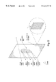
- FIG. 4A is a schematic perspective view drawing of a holographic diffraction system with grating on a transparent thin film surface
- FIG. 4B is a top view of a projection arrangement using the holographic diffraction system.
- FIG. 1 is a schematic diagram of a laser projection system incorporating red (R), green (G) and blue (B) lasers with holographic reflective viewing projection screen, illustrating the formation of narrow-angle viewing zone due to focusing by the viewing screen.
Abstract
Description
Claims (20)
Priority Applications (1)
| Application Number | Priority Date | Filing Date | Title |
|---|---|---|---|
| US09/355,598 US6414727B1 (en) | 1997-01-28 | 1998-01-28 | Video projection holographic screen, system and method |
Applications Claiming Priority (3)
| Application Number | Priority Date | Filing Date | Title |
|---|---|---|---|
| US3643897P | 1997-01-28 | 1997-01-28 | |
| US09/355,598 US6414727B1 (en) | 1997-01-28 | 1998-01-28 | Video projection holographic screen, system and method |
| PCT/US1998/001718 WO1998035498A1 (en) | 1997-01-28 | 1998-01-28 | Video projection holographic screen, system and method |
Publications (1)
| Publication Number | Publication Date |
|---|---|
| US6414727B1 true US6414727B1 (en) | 2002-07-02 |
Family
ID=21888611
Family Applications (1)
| Application Number | Title | Priority Date | Filing Date |
|---|---|---|---|
| US09/355,598 Expired - Lifetime US6414727B1 (en) | 1997-01-28 | 1998-01-28 | Video projection holographic screen, system and method |
Country Status (6)
| Country | Link |
|---|---|
| US (1) | US6414727B1 (en) |
| EP (1) | EP0956696A4 (en) |
| JP (1) | JP2001509918A (en) |
| AU (1) | AU723050B2 (en) |
| CA (1) | CA2279310A1 (en) |
| WO (1) | WO1998035498A1 (en) |
Cited By (17)
| Publication number | Priority date | Publication date | Assignee | Title |
|---|---|---|---|---|
| US6572229B2 (en) * | 2001-06-14 | 2003-06-03 | Carl Zeiss, Inc. | Back projection visual field tester |
| US6729728B2 (en) | 2001-06-14 | 2004-05-04 | Carl Zeiss Meditec, Inc. | Back projection visual field tester |
| US20040104663A1 (en) * | 2002-07-11 | 2004-06-03 | Shinjiro Umeya | Screen for image display apparatus, method for manufacturing screen for image display apparatus, and image display apparatus |
| WO2004099852A1 (en) * | 2003-05-06 | 2004-11-18 | Philips Intellectual Property & Standards Gmbh | Projection device for simultaneously generating a plurality of mutually spaced, holographic frames of one and the same image by means of a hologrphic screen |
| US20050030480A1 (en) * | 2001-12-21 | 2005-02-10 | Bose Corporation, A Delaware Corporation | Selective reflecting |
| US20050105176A1 (en) * | 2001-12-21 | 2005-05-19 | Bose Corporation | Light enhancing |
| US20050231800A1 (en) * | 2001-12-21 | 2005-10-20 | Barret Lippey | Selective reflecting |
| US20060181769A1 (en) * | 2005-01-21 | 2006-08-17 | Dai Nippon Printing Co., Ltd. | Transmitting-reflecting projection screen, and projection system comprising the same |
| US20060256292A1 (en) * | 2005-05-12 | 2006-11-16 | Barret Lippey | Color gamut improvement in presence of ambient light |
| US20070097509A1 (en) * | 2005-10-31 | 2007-05-03 | Nevitt Timothy J | Optical elements for high contrast applications |
| US20080239497A1 (en) * | 2007-03-29 | 2008-10-02 | Barret Lippey | Selective absorbing |
| US20090002816A1 (en) * | 2007-06-29 | 2009-01-01 | Barret Lippey | Selective Reflecting for Laser Projector |
| US7515336B2 (en) | 2001-12-21 | 2009-04-07 | Bose Corporation | Selective reflecting |
| US8284234B2 (en) | 2009-03-20 | 2012-10-09 | Absolute Imaging LLC | Endoscopic imaging using reflection holographic optical element for autostereoscopic 3-D viewing |
| US20140026384A1 (en) * | 2012-07-27 | 2014-01-30 | Nb Tech Inc. | Visual display system and method of constructing a high-gain reflective beam-splitter |
| WO2014193480A1 (en) * | 2013-05-28 | 2014-12-04 | Fusao Ishii | High contrast projection screen |
| USD893579S1 (en) * | 2017-07-17 | 2020-08-18 | Shared Space Studios LLC | At-home portal device |
Families Citing this family (2)
| Publication number | Priority date | Publication date | Assignee | Title |
|---|---|---|---|---|
| FR2800176B1 (en) * | 1999-10-25 | 2002-01-18 | Gerard Debard | HIGH DEFINITION IMAGE SCREEN BRIGHTNESS AMPLIFIER |
| DE10245881A1 (en) * | 2002-09-30 | 2004-04-08 | Fraunhofer-Gesellschaft zur Förderung der angewandten Forschung e.V. | Contrast-increasing screen |
Citations (17)
| Publication number | Priority date | Publication date | Assignee | Title |
|---|---|---|---|---|
| US4720747A (en) | 1984-04-26 | 1988-01-19 | Corporation For Laser Optics Research | Sequential plane projection by laser video projector |
| US4851918A (en) | 1984-04-26 | 1989-07-25 | Corporation For Laser Optic Research | Sequential plane projection by laser video projector |
| EP0373821A2 (en) | 1988-12-16 | 1990-06-20 | Hughes Aircraft Company | Holographic full color data retrieval and projection system |
| JPH04136885A (en) | 1990-09-28 | 1992-05-11 | Toppan Printing Co Ltd | Reflection type screen for projection television using lippman hologram |
| JPH04355747A (en) | 1991-06-04 | 1992-12-09 | Fujitsu Ltd | Three-dimentional display device |
| JPH0588020A (en) | 1991-09-30 | 1993-04-09 | Fujitsu Ltd | Display device |
| US5253073A (en) | 1992-04-01 | 1993-10-12 | Corporation For Laser Optics Research | Electronic data multiplexing in a full color pulsed laser projector and method |
| JPH05333435A (en) | 1992-06-01 | 1993-12-17 | Toyobo Co Ltd | Screen for projection by hologram |
| US5296965A (en) | 1992-01-10 | 1994-03-22 | Kuraray Co., Ltd. | Reflection-type screen |
| US5311321A (en) | 1993-04-22 | 1994-05-10 | Corporation For Laser Optics Research | Laser video imaging system with pulse backtrack and method |
| US5335022A (en) | 1992-01-31 | 1994-08-02 | Bell Communications Research, Inc. | High-contrast front projection video display system |
| JPH0723345A (en) | 1993-06-21 | 1995-01-24 | Matsushita Electric Ind Co Ltd | Time base correcting device |
| WO1995034832A1 (en) | 1992-12-15 | 1995-12-21 | Thomson-Csf | Holographic projection screen and method for its production |
| US5486884A (en) | 1993-10-06 | 1996-01-23 | U.S. Philips Corporation | Reflecting image projection screen and image projection system comprising such a screen |
| US5621486A (en) | 1995-06-22 | 1997-04-15 | International Business Machines Corporation | Efficient optical system for a high resolution projection display employing reflection light valves |
| WO1998035260A1 (en) | 1997-02-07 | 1998-08-13 | Daimler-Benz Ag | Holographic display screen for airplanes and vehicles |
| US6147801A (en) * | 1995-04-06 | 2000-11-14 | Philips Electronics North America Corp. | Rear projection screen with reduced speckle |
-
1998
- 1998-01-28 US US09/355,598 patent/US6414727B1/en not_active Expired - Lifetime
- 1998-01-28 WO PCT/US1998/001718 patent/WO1998035498A1/en not_active Application Discontinuation
- 1998-01-28 AU AU62553/98A patent/AU723050B2/en not_active Expired
- 1998-01-28 EP EP98904756A patent/EP0956696A4/en not_active Withdrawn
- 1998-01-28 CA CA002279310A patent/CA2279310A1/en not_active Abandoned
- 1998-01-28 JP JP53479798A patent/JP2001509918A/en active Pending
Patent Citations (18)
| Publication number | Priority date | Publication date | Assignee | Title |
|---|---|---|---|---|
| US4851918A (en) | 1984-04-26 | 1989-07-25 | Corporation For Laser Optic Research | Sequential plane projection by laser video projector |
| US4720747A (en) | 1984-04-26 | 1988-01-19 | Corporation For Laser Optics Research | Sequential plane projection by laser video projector |
| EP0373821A2 (en) | 1988-12-16 | 1990-06-20 | Hughes Aircraft Company | Holographic full color data retrieval and projection system |
| US5011244A (en) | 1988-12-16 | 1991-04-30 | Hughes Aircraft Company | Holographic full color data retrieval and projection system |
| JPH04136885A (en) | 1990-09-28 | 1992-05-11 | Toppan Printing Co Ltd | Reflection type screen for projection television using lippman hologram |
| JPH04355747A (en) | 1991-06-04 | 1992-12-09 | Fujitsu Ltd | Three-dimentional display device |
| JPH0588020A (en) | 1991-09-30 | 1993-04-09 | Fujitsu Ltd | Display device |
| US5296965A (en) | 1992-01-10 | 1994-03-22 | Kuraray Co., Ltd. | Reflection-type screen |
| US5335022A (en) | 1992-01-31 | 1994-08-02 | Bell Communications Research, Inc. | High-contrast front projection video display system |
| US5253073A (en) | 1992-04-01 | 1993-10-12 | Corporation For Laser Optics Research | Electronic data multiplexing in a full color pulsed laser projector and method |
| JPH05333435A (en) | 1992-06-01 | 1993-12-17 | Toyobo Co Ltd | Screen for projection by hologram |
| WO1995034832A1 (en) | 1992-12-15 | 1995-12-21 | Thomson-Csf | Holographic projection screen and method for its production |
| US5311321A (en) | 1993-04-22 | 1994-05-10 | Corporation For Laser Optics Research | Laser video imaging system with pulse backtrack and method |
| JPH0723345A (en) | 1993-06-21 | 1995-01-24 | Matsushita Electric Ind Co Ltd | Time base correcting device |
| US5486884A (en) | 1993-10-06 | 1996-01-23 | U.S. Philips Corporation | Reflecting image projection screen and image projection system comprising such a screen |
| US6147801A (en) * | 1995-04-06 | 2000-11-14 | Philips Electronics North America Corp. | Rear projection screen with reduced speckle |
| US5621486A (en) | 1995-06-22 | 1997-04-15 | International Business Machines Corporation | Efficient optical system for a high resolution projection display employing reflection light valves |
| WO1998035260A1 (en) | 1997-02-07 | 1998-08-13 | Daimler-Benz Ag | Holographic display screen for airplanes and vehicles |
Cited By (31)
| Publication number | Priority date | Publication date | Assignee | Title |
|---|---|---|---|---|
| US6572229B2 (en) * | 2001-06-14 | 2003-06-03 | Carl Zeiss, Inc. | Back projection visual field tester |
| US6688744B2 (en) | 2001-06-14 | 2004-02-10 | Carl Zeiss Meditec, Inc. | Back projection visual field tester |
| US6729728B2 (en) | 2001-06-14 | 2004-05-04 | Carl Zeiss Meditec, Inc. | Back projection visual field tester |
| US7535636B2 (en) | 2001-12-21 | 2009-05-19 | Bose Corporation | Selective reflecting |
| US20070133088A1 (en) * | 2001-12-21 | 2007-06-14 | Bose Corporation, A Delaware Corporation | Selective reflecting |
| US20050030480A1 (en) * | 2001-12-21 | 2005-02-10 | Bose Corporation, A Delaware Corporation | Selective reflecting |
| US20050105176A1 (en) * | 2001-12-21 | 2005-05-19 | Bose Corporation | Light enhancing |
| US20050231800A1 (en) * | 2001-12-21 | 2005-10-20 | Barret Lippey | Selective reflecting |
| US7520624B2 (en) | 2001-12-21 | 2009-04-21 | Bose Corporation | Light enhancing |
| US7515336B2 (en) | 2001-12-21 | 2009-04-07 | Bose Corporation | Selective reflecting |
| US7035006B2 (en) * | 2002-07-11 | 2006-04-25 | Sony Corporation | Screen for image display apparatus, method for manufacturing screen for image display apparatus, and image display apparatus |
| US20040104663A1 (en) * | 2002-07-11 | 2004-06-03 | Shinjiro Umeya | Screen for image display apparatus, method for manufacturing screen for image display apparatus, and image display apparatus |
| WO2004099852A1 (en) * | 2003-05-06 | 2004-11-18 | Philips Intellectual Property & Standards Gmbh | Projection device for simultaneously generating a plurality of mutually spaced, holographic frames of one and the same image by means of a hologrphic screen |
| CN100434967C (en) * | 2003-05-06 | 2008-11-19 | 皇家飞利浦电子股份有限公司 | Projection device for simultaneously generating a plurality of mutually spaced, holographic frames of one and the same image by means of a hologrphic screen |
| US7503656B2 (en) | 2003-05-06 | 2009-03-17 | Koninklijke Philips Electronics, N.V. | Projection device for simultaneously generating a plurality of mutually spaced, holographic frames of one and the same image by means of a holographic screen |
| US20060274271A1 (en) * | 2003-05-06 | 2006-12-07 | Koninklijke Philips Electronics N. V. | Projection device for simultaneously generating a plurality of mutually spaced, holographic frames of one and the same image by means of a holographic screen |
| US7719762B2 (en) * | 2005-01-21 | 2010-05-18 | Dai Nippon Printing Co., Ltd. | Transmitting-reflecting projection screen, and projection system comprising the same |
| US20060181769A1 (en) * | 2005-01-21 | 2006-08-17 | Dai Nippon Printing Co., Ltd. | Transmitting-reflecting projection screen, and projection system comprising the same |
| US7517091B2 (en) | 2005-05-12 | 2009-04-14 | Bose Corporation | Color gamut improvement in presence of ambient light |
| US20060256292A1 (en) * | 2005-05-12 | 2006-11-16 | Barret Lippey | Color gamut improvement in presence of ambient light |
| US20070097509A1 (en) * | 2005-10-31 | 2007-05-03 | Nevitt Timothy J | Optical elements for high contrast applications |
| US20080239497A1 (en) * | 2007-03-29 | 2008-10-02 | Barret Lippey | Selective absorbing |
| US8081368B2 (en) | 2007-03-29 | 2011-12-20 | Bose Corporation | Selective absorbing |
| US20090002816A1 (en) * | 2007-06-29 | 2009-01-01 | Barret Lippey | Selective Reflecting for Laser Projector |
| US7710645B2 (en) | 2007-06-29 | 2010-05-04 | Bose Corporation | Selective reflecting for laser projector |
| US8284234B2 (en) | 2009-03-20 | 2012-10-09 | Absolute Imaging LLC | Endoscopic imaging using reflection holographic optical element for autostereoscopic 3-D viewing |
| US20140026384A1 (en) * | 2012-07-27 | 2014-01-30 | Nb Tech Inc. | Visual display system and method of constructing a high-gain reflective beam-splitter |
| US9211481B2 (en) * | 2012-07-27 | 2015-12-15 | Nb Tech Inc. | Visual display system and method of constructing a high-gain reflective beam-splitter |
| US10108020B2 (en) | 2012-07-27 | 2018-10-23 | Nb Tech Inc. | Visual display system for a high-gain reflective beam-splitter |
| WO2014193480A1 (en) * | 2013-05-28 | 2014-12-04 | Fusao Ishii | High contrast projection screen |
| USD893579S1 (en) * | 2017-07-17 | 2020-08-18 | Shared Space Studios LLC | At-home portal device |
Also Published As
| Publication number | Publication date |
|---|---|
| AU6255398A (en) | 1998-08-26 |
| AU723050B2 (en) | 2000-08-17 |
| WO1998035498A1 (en) | 1998-08-13 |
| EP0956696A1 (en) | 1999-11-17 |
| JP2001509918A (en) | 2001-07-24 |
| CA2279310A1 (en) | 1998-08-13 |
| EP0956696A4 (en) | 2001-03-14 |
Similar Documents
| Publication | Publication Date | Title |
|---|---|---|
| US6414727B1 (en) | Video projection holographic screen, system and method | |
| US5112121A (en) | Display system for multiviewer training simulators | |
| US6999071B2 (en) | Method and apparatus for displaying 3d images | |
| US6509982B2 (en) | Holographic diffusers | |
| US4500163A (en) | Holographic projection screen | |
| US4736214A (en) | Apparatus and method for producing three-dimensional images from two-dimensional sources | |
| CN111133754B (en) | Optical device with phase modulation layer and phase compensation layer | |
| US20020159109A1 (en) | Projection screen apparatus including holographic optical element | |
| KR20010042282A (en) | Projector and display both comprising optical element for diffraction and scattering | |
| US20070139767A1 (en) | Stereoscopic image display apparatus | |
| JP4703477B2 (en) | 3D display device | |
| US20020101657A1 (en) | Stereoscopic display device | |
| US20060176554A1 (en) | Holographic louver device for a light guide screen | |
| JP2001183605A (en) | Floodlighting and display device using optical element for diffraction and scattering | |
| JP2003057595A (en) | Three-dimensional display device | |
| KR102054423B1 (en) | Reflection type holographic optical element and manufacturing method thereof, and screen device with reflection type holographic optical element | |
| JP4666543B2 (en) | Reflective hologram screen | |
| JP2003255464A (en) | Video display apparatus and hologram screen | |
| KR100822783B1 (en) | Autostereoscopic projection system and method of manufacturing a holographic screen | |
| JP2000132074A (en) | Hologram and screen using hologram | |
| JP2004004607A (en) | Hologram screen manufacturing method | |
| Shires | Real-time flat-panel solid state holographic stereogram | |
| JPH11142785A (en) | Kaleidoscope | |
| CN117111192A (en) | Manufacturing method and system of grating scattering screen, transparent display projection system and signal lamp | |
| JP2000338910A (en) | Holographic display device |
Legal Events
| Date | Code | Title | Description |
|---|---|---|---|
| AS | Assignment |
Owner name: CORPORATION FOR LASER OPTICS RESEARCH, NEW HAMPSHI Free format text: ASSIGNMENT OF ASSIGNORS INTEREST;ASSIGNOR:BENTON, STEPHEN A.;REEL/FRAME:010267/0311 Effective date: 19990723 |
|
| STCF | Information on status: patent grant |
Free format text: PATENTED CASE |
|
| FPAY | Fee payment |
Year of fee payment: 4 |
|
| FEPP | Fee payment procedure |
Free format text: PAT HOLDER CLAIMS SMALL ENTITY STATUS, ENTITY STATUS SET TO SMALL (ORIGINAL EVENT CODE: LTOS); ENTITY STATUS OF PATENT OWNER: SMALL ENTITY |
|
| FPAY | Fee payment |
Year of fee payment: 8 |
|
| FEPP | Fee payment procedure |
Free format text: PAYER NUMBER DE-ASSIGNED (ORIGINAL EVENT CODE: RMPN); ENTITY STATUS OF PATENT OWNER: SMALL ENTITY Free format text: PAYOR NUMBER ASSIGNED (ORIGINAL EVENT CODE: ASPN); ENTITY STATUS OF PATENT OWNER: SMALL ENTITY |
|
| FPAY | Fee payment |
Year of fee payment: 12 |
|
| AS | Assignment |
Owner name: JOHNSTONE, C. BRUCE, MASSACHUSETTS Free format text: SECURED PARTY BILL OF SALE;ASSIGNOR:JOHNSTONE, C. BRUCE;REEL/FRAME:034893/0476 Effective date: 20150114 |
|
| AS | Assignment |
Owner name: CHRISTIE DIGITAL SYSTEMS USA, INC., CALIFORNIA Free format text: ASSIGNMENT OF ASSIGNORS INTEREST;ASSIGNOR:JOHNSTONE, C. BRUCE;REEL/FRAME:046136/0678 Effective date: 20150601 |