US6414673B1 - Transmitter pen location system - Google Patents
Transmitter pen location system Download PDFInfo
- Publication number
- US6414673B1 US6414673B1 US09/189,299 US18929998A US6414673B1 US 6414673 B1 US6414673 B1 US 6414673B1 US 18929998 A US18929998 A US 18929998A US 6414673 B1 US6414673 B1 US 6414673B1
- Authority
- US
- United States
- Prior art keywords
- output signal
- transmitter
- signal
- pen
- movable device
- Prior art date
- Legal status (The legal status is an assumption and is not a legal conclusion. Google has not performed a legal analysis and makes no representation as to the accuracy of the status listed.)
- Expired - Lifetime
Links
Images


Classifications
-
- G—PHYSICS
- G01—MEASURING; TESTING
- G01S—RADIO DIRECTION-FINDING; RADIO NAVIGATION; DETERMINING DISTANCE OR VELOCITY BY USE OF RADIO WAVES; LOCATING OR PRESENCE-DETECTING BY USE OF THE REFLECTION OR RERADIATION OF RADIO WAVES; ANALOGOUS ARRANGEMENTS USING OTHER WAVES
- G01S5/00—Position-fixing by co-ordinating two or more direction or position line determinations; Position-fixing by co-ordinating two or more distance determinations
- G01S5/18—Position-fixing by co-ordinating two or more direction or position line determinations; Position-fixing by co-ordinating two or more distance determinations using ultrasonic, sonic, or infrasonic waves
- G01S5/30—Determining absolute distances from a plurality of spaced points of known location
-
- G—PHYSICS
- G01—MEASURING; TESTING
- G01S—RADIO DIRECTION-FINDING; RADIO NAVIGATION; DETERMINING DISTANCE OR VELOCITY BY USE OF RADIO WAVES; LOCATING OR PRESENCE-DETECTING BY USE OF THE REFLECTION OR RERADIATION OF RADIO WAVES; ANALOGOUS ARRANGEMENTS USING OTHER WAVES
- G01S5/00—Position-fixing by co-ordinating two or more direction or position line determinations; Position-fixing by co-ordinating two or more distance determinations
- G01S5/18—Position-fixing by co-ordinating two or more direction or position line determinations; Position-fixing by co-ordinating two or more distance determinations using ultrasonic, sonic, or infrasonic waves
- G01S5/20—Position of source determined by a plurality of spaced direction-finders
-
- G—PHYSICS
- G06—COMPUTING; CALCULATING OR COUNTING
- G06F—ELECTRIC DIGITAL DATA PROCESSING
- G06F3/00—Input arrangements for transferring data to be processed into a form capable of being handled by the computer; Output arrangements for transferring data from processing unit to output unit, e.g. interface arrangements
- G06F3/01—Input arrangements or combined input and output arrangements for interaction between user and computer
- G06F3/03—Arrangements for converting the position or the displacement of a member into a coded form
- G06F3/041—Digitisers, e.g. for touch screens or touch pads, characterised by the transducing means
- G06F3/043—Digitisers, e.g. for touch screens or touch pads, characterised by the transducing means using propagating acoustic waves
Definitions
- the invention relates to the field of location algorithms for remote devices. More particularly, the invention relates to an algorithm system for determining the position of an electronic pointing device.
- Digitizing pen and whiteboard systems are used for a variety of electronic applications. These systems typically include a whiteboard, a position indicating pen, and associated electronics for determining the interaction between the whiteboard and the position indicating pen. A digital data signal is typically derived to represent the relative position of the position indicating pen and the whiteboard.
- a signal such as ultrasound
- the algorithm computes radii to each of the two microphones using information from only a single sonic pulse sample, translates the two radii into a calculated X,Y location, and then filters the calculated X,Y values, removing them from the described path if they vary from a specified limit, or range.
- U.S. Pat. No. 5,142,506 discloses a “positional locating method and apparatus for measuring distances by accurately determining the transit time of ultrasonic wave bursts between two or more points”. “Timer clocks are started when each of the bursts is triggered to be emitted from a transmission point, and are stopped when a highly defined point in the burst is received at a corresponding receiving point. The highly defined point is determined by first analyzing the burst to identify a particular cycle within the burst. The particular cycle is then analyzed to detect the specific point within the cycle”.
- Analog systems such as described by Edwards, are inherently limited to “on the fly” comparison between a current signal burst and a small amount of amplitude information from a single prior signal. Since analog systems do not store the entire prior signal bursts in memory, they are limited to the comparison of a small number of features on the last prior signal.
- Common variations of the waveform, typically due to ordinary use of a transmitter, either from the orientation of the transmitter to the receivers, the speed at which the transmitter is moved between different regions of a writing surface, the signal strength of the transmitted signal, noise, or reflections can result in erroneous results. Reliance on the amplitude of a specific cycle within a pulse waveform can lead to errors of one or more cycles, resulting in position detection errors of several centimeters.
- acoustic mouse system which “controls indications on an X-Y surface of the face of a display.
- the system comprises at least three acoustic receivers in an x-y plane, and a hand movable acoustic transmitter that is movable both parallel to the x-y plane and in a z direction perpendicular to the x-y plane.
- the transmitter generates periodic acoustic oscillations in the direction of the support and its receivers.
- Detection circuitry responsive to the signals from the acoustic receivers, provides signals indicative of the absolute position of the acoustic transmitter in the x-y plane.
- a processor is responsive to the signals from the detection circuitry to provide absolute position signals to the display, whereby the display responds by moving an indication to a corresponding position on the X-Y surface of the display face.
- the detector circuitry is further enabled to provide z position signals to the display, whereby the display may modify a display function in accordance with the z position signals”.
- Gilchrist discloses a generic, periodic acoustic wavelength position indicating system
- Gilchrist fails to disclose a useful algorithm by which the position of the movable acoustic transmitter is determined by the detection circuitry, either by the direction of arrival or by the time of arrival of a transmitter signal.
- the system apparently requires a minimum of three acoustic receiver locations to properly locate the movable acoustic transmitter.
- Gilchrist also fails to disclose waveform analysis techniques which can be used to provide sufficient accuracy in the determination of the movable acoustic transmitter.
- the disclosed prior art systems and methodologies thus provide basic transmitter pen and whiteboard positioning systems for determining the spatial relationship between a pen and a writing area, but fail to provide an accurate means for determining the position of the tip of the pen.
- the development of such a transmitter pen positioning system would constitute a major technological advance.
- the development of such a transmitter pen positioning system which also provides a means for communicating supplementary information between a transmitter pen and external receivers would constitute a further major technological advance.
- a transmitter pen location system in which a pen is adapted to send a repeated output signal to external receivers at two or more receiver locations, wherein the location of the pointing tip of the pen is determined in relation to the writing surface of a whiteboard.
- an output element preferably an ultrasonic transducer, transmits an output signal from the transmitter pen to two or more external receivers at two or more receiver locations. The direction of arrival of the output signal to each of the receiver locations is determined, and the position of the pointing tip of the transmitter pen is then determined, as the intersection of direction vectors from the pen to the external receivers.
- the transducer transmits an output signal from the transmitter pen to three or more external receivers, wherein the received signal is processed to determine the time of arrival to each of the receivers, and the location of the pointing tip of the pen is determined as the calculated distance between the transducer and each of the receivers.
- a third receiver located at a receiver location is used to determine the time of arrival of a secondary output signal, to determine the distance between the dual signal transmitter pen and the receiver location, while two or more receivers at the receiver location are used to determine the direction of arrival of the primary output signal.
- Alternative embodiments allow the transmission of supplementary information from the transmitter pen to the receivers, using waveshaping of the output signal.
- FIG. 1 is a top view of a direction of arrival transmitter pen location system, in which a single signal transmitter pen is located within the writing area of a white board, and in which the transmitter pen periodically sends an output signal to external receivers;
- FIG. 2 shows the geometric relationship between a single signal transmitter pen and two external receiver locations
- FIG. 3 is a partial top view of receiver locations located on a surface
- FIG. 4 is a perspective view of an alternate embodiment of a direction of arrival transmitter pen location system, in which a single signal transmitter pen is located within a writing volume;
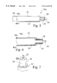
- FIG. 5 is a partial cutaway view of a single signal transmitter pen having an output signal transducer
- FIG. 6 is a detailed cutaway view of the pointing tip of a single signal transmitter pen having an output signal transducer
- FIG. 7 is a partial perspective view of the pointing tip of a single signal transmitter pen having a single output signal transducer
- FIG. 8 is schematic view of the transmission of an output signal from a single signal transmitter pen
- FIG. 9 shows a shaped pulse waveform of one embodiment of an output signal sent from a transmitter pen
- FIG. 10 shows a calculated transcribed path of a single signal transmitter pen from sequential locations within the writing area of a white board
- FIG. 11 shows a periodic output signal pulse train as it is sent from a single signal transmitter pen
- FIG. 12 shows an output signal as it arrives at a first external receiver at a first receiver location
- FIG. 13 shows an output signal as it arrives at a first external receiver at a second receiver location
- FIG. 14 shows the phase difference of an output signal arriving at two external receivers, which is used by the signal processor to determine the direction of arrival of the output signal;
- FIG. 15 shows an output signal arriving at a first external receiver at a first receiver location
- FIG. 16 shows an output signal arriving at a second external receiver at a first receiver location
- FIG. 17 is a perspective view showing changes in transmitter pen orientation which can alter the received waveform of the second output signal as it arrives at an external receiver;
- FIG. 18 a top view showing the directional reception characteristics of one embodiment of second output sensors at external receivers
- FIG. 19 is an alternate embodiment of the transmitter pen location system, having movable receivers, an automatic-calibration transmitter, and wireless communication between the receivers and the signal processor;
- FIG. 20 is a top view of a time of arrival transmitter pen location system, which shows the geometric relationship between a single signal transmitter pen and three external receivers, with the calculated position of the single signal transmitter pen shown as the intersection of three arc lengths;
- FIG. 21 shows an ultrasound pulse train signal as it is received at a first receiver location in a time of arrival transmitter pen location system
- FIG. 22 shows an ultrasound pulse train signal as it is received at a second receiver location in a time of arrival transmitter pen location system
- FIG. 23 shows an ultrasound pulse train signal as it is received at a third receiver location in a time of arrival transmitter pen location system
- FIG. 24 shows a large writing area direction of arrival transmitter pen location system, in which a white board transmitter sends a return signal to a transmitter pen having a receiver circuit; allowing the period between subsequent output signals to be controlled; and
- FIG. 25 shows a large writing area single signal transmitter pen having a receiver circuit
- FIG. 26 is a top view of a combined direction and time of arrival dual-signal transmitter pen location system, in which a dual signal transmitter pen is located within the writing area of a surface;
- FIG. 27 is a partial top view of a combined direction and time of arrival, dual signal receiver pod located on a surface
- FIG. 28 is a partial cutaway view of a dual signal transmitter pen having a first output signal transducer and a second output signal transducer;
- FIG. 29 is a detailed cutaway view of the pointing tip of a dual signal transmitter pen
- FIG. 30 is a partial perspective view of the pointing tip of a dual signal transmitter pen
- FIG. 31 is schematic view of the transmission of first output signal and a second output signal from a dual signal transmitter pen
- FIG. 32 shows a repeated dual output signal as it is sent from a dual signal transmitter pen
- FIG. 33 shows a secondary output signal that includes encoded information which indicates a pen up position and supplementary information
- FIG. 34 shows a secondary output signal that includes encoded information which indicates a pen down position and supplementary information.
- FIG. 1 is a top view of a single signal transmitter pen 30 a located within the writing area 14 of a surface 12 , in which the single signal transmitter pen 30 a repeatedly sends a time dependent output signal 16 to at least two external receivers 20 a, 20 b at each of two receiver locations 18 a and 18 b.
- the surface 12 is typically a whiteboard, a blackboard, a drafting table, an overhead projector, a projector screen, or any kind of presentation surface.
- a first incline angle ⁇ 1 15 a is defined between the first receiver location 18 a and the direction of transmission of the output signal 16 .
- a second incline angle ⁇ 2 15 b is defined between the second receiver location 18 b and the direction of transmission of the output signal 16 .
- the single signal transmitter pen 30 a has a transducer element 28 (FIGS. 5-8) having an output signal 16 , which is used to determine the location of the pointing tip 36 (FIGS. 5-7) of the single signal transmitter pen 30 a, in relation to the writing area 14 of a surface 12 within a transmitter pen location system 10 a, 10 b, 10 c.
- the output transducer 28 transmits a time dependent output signal 16 from the single signal transmitter pen 30 to the external receivers 20 a, 20 b at receiver locations 18 a and 18 b.
- the output signal 16 which is repeatedly transmitted from the single signal transmitter pen 30 a, typically in a periodic manner, arrives at two or more receiver locations 18 , at times which are dependent on the velocity of the output signal 16 and the distance from the transmitter pen 30 a to each of the receivers 20 a, 20 b.
- the frequency of the output signal 16 lies within the ultrasound frequency spectrum.
- the signal 16 is sampled by the signal processor. 57 (FIG. 8 ), such as by an A/D converter at either the receiver locations 18 a, 18 b or the signal processor 57 .
- the sampled signal 16 is then transferred to the signal processor 57 (FIG. 8 ).
- the location of the pointing tip 36 (FIGS.
- the transmitter pen 30 is then determined by the signal processor 57 , by measuring the relative phase difference of the output signal 16 between external receivers 20 a, 20 b at each receiver location 18 a, 18 b, using the difference in the phase of the arriving output signal 16 at each receiver 20 a and 20 b to determine the direction of arrival 15 a, 15 b of the output signal 16 to each of the receiver locations 18 a, 18 b, and then by determining the location of the single signal transmitter pen 30 a, based on the simultaneous calculated directions 15 a, 15 b to each of the receiver locations 18 a, 18 b.
- FIG. 2 shows the geometric relationship 21 between a single signal transmitter pen 30 a and two external receivers 18 , with the calculated (X 1 ,Y 1 ) position 22 of the single signal transmitter pen 30 a represented in relation to an X-axis 24 and a Y-axis 26 .
- the distance d a between the first receiver location 18 a and the calculated (X 1 ,Y 1 ) position 22 is defined along direction vector 23 a.
- the distance d b between the second external receiver location 18 b and the calculated (X 1 ,Y 1 ) position 22 is defined along direction vector 23 b.
- the (X 1 , Y 1 ) position 22 of the single signal transmitter pen 30 a is shown, and is calculated, as the intersection 22 of the first direction vector 23 a and the second direction vector 23 b within the writing area 14 .
- FIG. 3 is a partial top view of external receivers 20 a, 20 b at receiver locations 18 a, 18 b, which are located on a surface 12 .
- the first receiver location 18 a includes a first external receiver 20 a and a second external receiver 20 b, and includes a signal connection 55 a towards a signal processor 57 (FIG. 10 ).
- the second receiver location 18 b also includes a first external receiver 20 a and a second external receiver 20 b, and includes a signal connection 55 b to the signal processor 57 .
- the direction of arrival transmitter pen location process (FIGS. 1-4, 10 ), which uses an output signal 16 to locate the single signal transmitter pen 30 a relative to the writing area 14 of a white board 12 , comprises the following steps:
- FIG. 4 is a perspective view of an alternate embodiment of the direction of arrival transmitter pen location system 10 b, in which a single signal transmitter pen 30 a is located within a writing volume 14 b, and in which the single signal transmitter pen 30 a periodically sends an output signal 16 to external receivers 20 a and 20 b at each of three receiver locations 18 a, 18 b, and 18 c.
- the geometric relationship between the single signal transmitter pen 30 a and the receiver locations 18 a, 18 b and 18 c is repeatedly determined, wherein the successive calculated (X,Y,Z) positions 31 a, 31 b, 31 c of the single signal transmitter pen 30 a describe a path 82 , in relation to an X-axis 24 , a Y-axis 26 , and a Z-axis 29 .
- FIG. 5 is a partial cutaway view of a single signal transmitter pen 30 a having an output signal transducer 28 , which is used with either the direction of arrival location system 10 a, 10 b, 10 c (FIGS. 1 , 2 , 4 , 10 ) or the time of arrival location system 10 d (FIG. 20 ). While the transmitter pen 30 a is described as a pen, it can be any sort of movable transmitter device.
- the transmitter circuitry 40 connected to the output signal transducer 28 through leads 46 a and 46 b, excites the output signal transducer 28 to produce an output signal 16 .
- the output signal 16 pulse train 89 (FIG. 11) has a periodic frequency of 100 pulses per second. It is preferred that the transmitter circuitry 40 include an out-of-phase driving mechanism, which effectively shapes and squelches the output-signal 16 to produce a short duration pulsed output signal 16 .
- FIG. 6 is a detailed cutaway view of the pointing tip 36 of a single signal transmitter pen 30 a having an output signal transducer 28 .
- FIG. 7 is a partial perspective view of the pointing tip 36 of a single signal transmitter pen 30 a having a single piezoelectric output signal transducer 28 .
- An optional finger guard 38 protects the output signal transducer 28 .
- FIG. 8 is schematic view 50 of the transmission of the output signal 16 from a single signal transmitter pen 30 a, which is typically an ultrasound output signal 16 .
- the output signal 16 is transmitted from one or more transducers 28 located near the pointing tip 36 of the single signal transmitter pen 30 a.
- the transducer 28 is a cylindrical layered piezoelectric layer 56 surrounded by an outer conductive layer 54 a and an inner conductive layer 54 b, which is connected to the transmitter circuitry 40 by leads 46 a and 46 b and lead connections 52 a and 52 b.
- the ultrasound transducer 28 used is Part No. AT/R 40-10P, manufactured by Nippon Ceramic Co. Ltd., of Tottori-Shi, Japan.
- the single signal transmitter pen 30 a repeatedly transmits output signals 16 , typically periodically, with a period 95 (FIG. 11 ).
- FIG. 9 shows a prior shaped pulse waveform 16 a and a present, subsequent shaped pulse waveform 16 b sent from either a single signal transmitter pen 30 a, 30 b (FIG. 25 ), or a dual signal transmitter pen 30 c (FIGS. 26, 28 - 30 ).
- an ultrasound second output signal 16 can have any waveform shape, including a single ultrasound pulse 72 , it is preferred that the waveform be shaped to have a short duration, with distinctive wave characteristics, which allows the waveform to be measured and compared accurately, to provide an accurate calculated position for a transmitter pen 30 .
- the subsequent second output signals 16 a, 16 b each include two major pulses 72 a and 72 b, with specific timing between them.
- each of the signals 16 retain major features, such as waveform characteristics 72 a, 72 b, as well as wavelength dependent features, such as peaks 76 a, 76 b, 76 c, and 76 d, the position of relative peaks 76 , and peak amplitudes. Comparison of these features between subsequent stored digitized output signals 16 a and current output signals 16 b allows the calculated transcribed path 82 of a transmitter pen 30 to be accurately determined. As well, the use of distinctive waveform characteristics 72 a, 72 b allows the transmission of other information to be sent from the transmitter pen 30 to the external receivers 20 , as, discussed below.
- Comparison of the present output signal 16 b to one or more stored output signals 16 a is preferably repeated for all external receivers 20 at each receiver location 18 , giving multiple estimates of the time of propagation of the output signal 16 b, and different arrays with the stored prior signals 16 a.
- FIG. 10 is a top view 80 of one embodiment of the direction of arrival transmitter pen location system 10 c, which shows a calculated transcribed path 82 of a single signal transmitter pen 30 a from sequential locations within the writing area 14 of a surface 12 .
- the receivers 18 are connected 55 to a signal processor 57 , which calculates successive X-Y locations 84 a, 84 b, . . . 84 n, in relation to a defined X-axis 24 and a Y-axis 26 .
- . . 84 n define a path 82 for the single signal transmitter pen 30 a.
- the successive X-Y locations 84 a, 84 b . . . 84 n, and the defined path 82 can then be stored or transferred by the signal processor 57 .
- a functional area 85 is defined within the writing area 14 of the surface 12 .
- Activation of the single signal transmitter pen 30 a within the functional area 85 is selectively used to send function commands to either the signal processor 57 , or to a computer 87 connected to the signal processor 57 .
- Function commands can be used to print the displayed image path 82 , save the image path 82 , create a new page, or to control functions on the connected computer 87 , such as by activating pull-down menus on a graphic-user interface (GUI) 93 on the connected computer 87 .
- GUI graphic-user interface
- a programmable control application 91 within the computer 87 communicates with the signal processor 57 , to control system options, such as waveform comparison algorithms, and the desired number of previous output signals 16 a to be stored 99 and compared to current output signals 16 b. Since the prior output signals 16 a are captured and stored in a digital manner, the comparison between prior output signals 16 a and current output signals 16 b can be efficiently monitored or modified through the programmable control application software 91 .
- FIG. 11 shows an output signal 16 as it is sent from a single signal transmitter pen 30 a, 30 b.
- the output signal pulse train 89 a is comprised of a repeated transmission of an output signal 16 .
- the repeated transmission of the output signal 16 is typically characterized by a period P 1 95 .
- the ultrasound output signal 16 arrives at each of the external receivers 20 a, 20 b at receiver locations 18 at times which are dependent on the speed of the output signal 16 , and the distance between the transmitter pen 30 and receivers 20 a, 20 b.
- FIG. 12 shows the output signal 16 as it arrives at a first external receiver 20 a of a first receiver location 18 a.
- FIG. 13 shows the same output signal 16 as it arrives at a first external receiver 20 a of a second, further receiver location 18 b.
- the time of arrival of the output signal 16 is dependent on the distance between the movable single signal transmitter pen 30 a, 30 b and each of the external receivers 20 a and 20 b.
- the difference in path length, for the arriving output signal 16 between neighboring receivers 20 a, 20 b, is seen as a shift in phase of the arriving output signal 16 , and is analyzed by the signal processor 57 to determine the direction of arrival 15 a, 15 b of the output signal 16 to each receiver location 18 .
- the accuracy of the location of the single signal transmitter pen 30 a is therefore dependent on the accuracy with which the signal processor 57 connected to the external receivers 20 at receiver locations 18 can consistently determine the direction of arrival 15 a, 15 b of the ultrasound signal waveform 16 .
- FIG. 14 is a graph showing a received output signal 16 at external receivers 20 a, 20 b at a receiver location 18 . Since the external receivers 20 a and 20 b are slightly offset from each other, the output signal 16 typically defines a slightly different path length to arrive at the external receivers 20 a and 20 b.
- the calculated phase difference 90 between the received output signal 16 at external receivers 20 a, 20 b at receiver location 18 a provides the first incline angle ⁇ 1 15 a.
- the calculated phase difference 90 between the received output signal 16 at external receivers 20 a, 20 b at receiver location 18 b is analyzed by the signal processor 57 , and provides the second incline angle ⁇ 2 15 b .
- the X,Y position of the transmitter pen is determined within the two-dimensional writing area 14 .
- Determination of the number of full cycle shifts that exists between received output signals 16 at separated external receivers 20 a and 20 b is accomplished by the signal processor 57 (FIG. 10 ). While there are differences-between the received amplitude of the output signals 16 at neighboring external receivers 20 a, 20 b at each receiver location, each of the signals 16 retain major features, such as waveform characteristics 72 a, 72 b, as well as wavelength dependent features, such as peaks 76 a, 76 b, 76 c, and 76 d, the position of relative peaks 76 , and peak amplitudes. Comparison of these features between digitized output signals 16 at neighboring receivers 20 a, 20 b allows the direction of arrival 15 a, 15 b of a second output signal 16 to be accurately determined.
- FIG. 15 and FIG. 16 show a typical system configuration, where the arrival of the output signal 16 at the first external receiver 20 a lags the arrival of the output signal 16 at the second external receiver 20 b by multiple wavelengths.
- FIG. 17 is a perspective view showing changes in transmitter pen orientation in relation to external receiver locations 18 a, 18 b, which can significantly alter the received waveform of the output signal 16 as it arrives at receiver locations 18 , 118 .
- the amplitude of the incoming waveform 16 can change significantly from the distance to each of the receiver locations 18 a, 18 b.
- Other factors also contribute to the attenuation of the output signal 16 , including the angular orientation 98 a, 98 b between the transmitter pen 30 and the external receivers 20 , the angle 96 of the inclined movable transmitter pen 30 against the surface of the writing area 14 , the axial rotation 97 of the transmitter pen 30 , and even the available source power to the output circuitry 40 within the transmitter pen 30 .
- the external receivers 20 a, 20 b within receiver locations 18 a, 18 b are typically placed at an angle of approximately 45 degrees in relation to a rectangular writing area 14 , to improve signal detection of the second output signal 16 .
- the direction of arrival, transmitter pen location system 10 a, 10 b, 10 c can accurately determine the location of the transmitter pen 30 , even when the output signal 16 is significantly attenuated.
- the direction of arrival transmitter pen location system 10 a, 10 b, 10 c includes simultaneous output: signals 16 a arriving at closely spaced external receivers 20 a, 20 b at each receiver location 18 . While the output signal 16 is commonly attenuated, as discussed above, attenuation characteristics are similar between the output signal as it received at closely spaced external receivers 20 a, 20 b. Therefore, the comparison of the received output signal 16 to calculate of direction of arrival yields accurate results.
- the direction of arrival transmitter pen location system 10 a, 10 b, 10 c advantageously stores one or more prior signals 16 a for each external receiver 20 a, 20 b, allowing the comparison of a large number of features between the current second output signal 16 b and one or more prior second output signals 16 a for each external 20 a, 20 b.
- the storage of the received signal 16 to memory 158 allows signal processing comparison techniques between the current output signal 16 b and the stored waveform 16 a to be performed, such as by cross-correlation methods. An accurate comparison between the features of the present 16 b and prior output signals 16 a can therefore be made.
- the second output signals 16 b arrive at the signal processor 57 , they are preferably normalized to prior stored signals 16 a.
- the received second output signals 16 b and one or more stored second output signals 16 a are normalized to each other, a valid comparison can be made between the normalized output signals 16 a, 16 b.
- the received output signals 16 b and one or more stored second output signals 16 a have widely varying signal strengths, it is still possible to cross-correlate features between the normalized signals, rather than to compare the amplitude of a limited number of data points.
- preferred embodiments of the direction of arrival transmitter pen location system 10 a, 10 b, 10 c allow changes to the comparison of features between the current second output signal 16 b and one or more stored prior second output signals 16 a.
- the programmable control application 91 (FIG. 10) is typically controllable and updatable, allowing the signal processor 57 to be updated, and to be easily adapted to different transmitter pens 30 , different surfaces 12 , and different external receivers 20 .
- the output signal characteristics of the circuitry 40 and characteristic transmitter output signal 16 can optionally communicate secondary information to the receiver locations 18 .
- Such supplementary information can include pen activation status, or pen types, such as different colored pens, or for pens of different widths, or even for calculated line types, such as for dashed lines.
- the transmitter pens 30 can optionally communicate the designated user of each transmitter pen 30 .
- FIG. 9 shows a typical output signal 16 b for a transmitter pen 30 in a “pen down” position.
- the output signal 16 b is modifiable by the transmitter circuitry 40 to designate different signal states, such as to communicate whether the pen is inactivated in a first “pen up” position, or in an activated second “pen down” position.
- the present output signal 16 b includes two waveform pulses 72 a, 72 b to designate a “pen down” position.
- the present output signal 16 b typically includes a single ultrasound pulse 72 a to designate a “pen up” position.
- the signal processor 57 determines that the transmitter pen 30 is currently in its “pen up” position.
- the “pen up” position typically means that the pointing tip 36 of the transmitter pen 30 is not in contact with either the writing area 14 of the surface 12 , or with another writing surface placed within the writing area 14 , such as a piece of paper.
- the signal processor 57 determines that the pen 30 is currently in its “pen down” position, and the directions of arrival 15 a, 15 b of the pen 30 are also determined.
- the “pen down” position 68 b typically means that the pen tip 36 is in contact with either the writing area 14 of the surface 12 , or with another writing surface placed within the writing area 14 , such as a piece of paper.
- the transmitter pen 30 As the transmitter pen 30 , is moved along a path 82 in the pen-down position, a series of output signals 16 are received at the external receivers 20 , from which successive directions of arrival are calculated, and subsequently X-Y coordinates are determined, to produce a representation of the path 82 of the transmitter pen 30 . In some embodiments, the position of the transmitter pen 30 is also calculated when the transmitter pen is not in contact with the writing area 14 .
- the transmitter circuitry 40 in the transmitter pen 30 preferably communicates pen attributes, and can include switching or continuous adjustment control to produce a transmitter signal 16 indicative of different pen attributes.
- a transmitter pen 30 which contains a single writing tip 36 having one color of ink, such as black ink, may be selectively adjusted by the user to produce an output signal 16 that corresponds to drawn paths 82 of varying colors, widths, or line styles. While the user draws or writes upon a writing surface 14 , such as a white board 12 , displaying a black path 82 (FIG. 10 ), such as figures or letters, the transmitted and processed signal for the path 82 is dependent upon the pen characteristics chosen by the user.
- FIG. 9 shows an output signal 16 that indicates a pen down position, using a two waveform pulses 72 , the addition and spacing of waveform pulses 72 are preferably used to communicate encoded supplementary information, such as designated color, width, line type, or author.
- the time between multiple waveform pulses 72 spans a time that is specific to a particular pen color.
- a first time delay between the waveform pulses 72 can specify al pen color of black, while a second time delay between the waveform pulses 72 can specify a pen color of blue.
- the direction of arrival transmitter pen location system 10 a, 10 b, 10 c offers significant advantages over prior art location methods.
- the use of an improved process for calculating the phase difference between arriving output signals 16 allows the directions of arrival 15 a, 15 b to be determined accurately, and allows the transmitter pen 30 to have a single transmitter 28 .
- the distance d 1 17 (FIG. 1) between receiver locations 18 can either be set once, such as for receiver locations 18 that are mounted a fixed distance from each other, or can be periodically set, such as for receiver locations 18 that can be remounted at different positions.
- the distance do between fixed receiver locations 18 can be stored within the signal processor 57 , such as for manufactured transmitter pen 30 and board systems 10 in which the distance between fixed receiver locations 18 is controlled by the design of the surface 12 .
- FIG. 19 is an alternate embodiment of the transmitter pen location system 10 d, in which the receiver locations 18 a, 18 b are movable, wherein a calibration transmitter 92 is added at one receiver location 18 b, providing automatic self-calibration for the system 10 d.
- An auto-calibration transmission signal 94 is sent from the receiver location 18 b, and is received at another receiver location 18 a.
- the signal processor 57 analyzes the incoming auto-calibration transmission signal 94 , and determines the distance d 1 between the receiver locations 18 a, 18 b.
- a wireless connection is provided between the receivers 18 a, 18 b and the signal processor 57 , wherein information data signals 160 a, 160 b are transmitted from the receiver locations 18 a, 18 b to the signal processor 57 .
- the direction of arrival transmitter pen location system 10 a, 10 b, 10 c can also be adapted to larger writing areas 14 .
- the period between subsequent output signal pulses 16 is determined by the largest distance across the writing area 14 .
- the single signal transmitter pen 30 b includes a pen receiver 144 , and the surface 12 includes a white board transmitter 102 , which in this embodiment is shown next to one of the receiver locations 18 b.
- the signal processor 57 determines that the single signal transmitter pen 30 b is far from one or more of the receiver locations 18 . The increased distance requires a longer period between subsequent output signals 16 . In this event, the signal processor 57 sends a return signal 104 to the transmitter pen receiver 144 through the white board transmitter 102 .
- the signal circuitry 40 within the single signal transmitter pen 30 b then controllably lowers the frequency of transmission of output signals 16 , in response to the return signal 104 .
- Lowering the transmitted frequency of the single signal pulse train 89 a allows each of the output signals 16 to reach the furthest of each of the external receiver locations 18 before the transmission of a subsequent output signal 16 , so that there is no overlap of information between receipt of the output signals 16 .
- the large area system 10 e allows the single signal transmitter pen 30 b to be located accurately over a large writing area 14 .
- FIG. 20 is a top view of a time of arrival transmitter pen location system 10 e, which shows the geometric relationship between a single signal transmitter pen 30 a, 30 b and three or more external receiver locations 18 a, 18 b, 18 c, each having a single external receiver 20 .
- the position of the single signal transmitter pen 30 a, 30 b is calculated as the intersection of three arc lengths 101 a, 101 b and 101 c .
- receiver locations 18 a, 18 b, . . . 18 n one of the signal paths 16 acts as a relative starting point for the other signal paths 16 .
- the signal processor 57 preferably compares repeatable reference points 77 (FIG. 9) between present signals 16 b arriving at each receiver 18 a, 18 b, 18 c and one or more stored prior output signals 16 a for each receiver 18 a, 18 b, 18 c.
- Any repeatable reference point 77 on the output ultrasound signal waveform 16 is sufficient to compare a present output ultrasound signal waveform 16 b arriving at an receiver location 18 to a stored prior output ultrasound signal waveform 16 a arriving at the same receiver location 18 b, as long as the repeatable reference point 77 is consistently identified on the current output ultrasound signal waveform 16 b and on the stored prior output ultrasound signal waveform 16 a.
- the crossing time threshold 73 indicates a starting point for the repeated ultrasound output signals 16 .
- time of arrival transmitter pen location system 10 e it is preferred to use a linearly decaying ultrasound threshold 73 , since the amplitude of the ultrasound signal 16 falls off like 1/r with distance.
- N the number of receiver locations 18 (where N ⁇ 3), as shown in FIG. 20, the ultrasound signal 16 is received at three or more external receiver locations 18 .
- the signal processor 57 finds a repeatable reference point 77 on the ultrasound output signal 16 a, 16 b, which in one embodiment lies between the threshold crossing 73 and the second peak 76 b.
- a threshold value 75 of 0.5 volts is used to determine points along the subsequent output signals 16 a, 16 b.
- the first point along the first output signal 16 a to cross the threshold value is located along the first peak 76 a.
- the first point along the second output signal 16 b to cross the threshold value 75 is located along the second peak 76 b. Since subsequent output signals 16 a, 16 b typically have different amplitudes, arbitrary measurement of a threshold 75 to determine a reference point 77 can yield differences between subsequent signals 16 on the order of a wavelength.
- the signal processor 57 preferably stores a prior output signal 16 a, and compares repeatable features between the present second output signal 16 b and the stored prior second output signal 16 a.
- Repeatable features that are distinguishable typically include the shape of major peaks 72 a, 72 b and minor peaks 76 a, 76 b, interpeak spacing, and the relative amplitude of the major peaks 72 a, 72 b and minor peaks 76 a, 76 b.
- the prior output signal 16 a is preferably stored, any or all features can be analyzed and compared, to determine an accurate repeatable reference point 77 . Even the combined relationship between sets of features can be compared.
- the current output signal 16 b and one or more stored prior output signals 16 a are energy-normalized, such that individual peaks 72 , 76 are fit to each other between the current output signal 16 b and the stored prior output signals 16 a.
- the normalized output signals are then compared for features that do not depend on the amplitude of separate points on the signals 16 a, 16 b, but on the relationship between features.
- the signal processor 57 adjusts the actual threshold crossing on peak 76 b on the present output signal 16 b by the period of one wavelength, to establish an adjusted threshold crossing 77 that is consistent with the features of the stored signal 16 a.
- the signal processor 57 preferably uses the previously received and stored pulse 16 a, from the same external receiver location 18 to determine the repeatable reference point 77 on the current ultrasound signal 16 b.
- This preferred comparison is performed for the present output signal 16 b and the prior output signal 16 a for each of the receiver locations 18 a, 18 b, 18 c.
- the output signal 16 a is preferably stored 99 for each external receiver 20 at receiver locations 18 , to provide an accurate comparison for subsequent output signals 16 arriving at each external receiver 20 .
- the current ultrasound signal 16 b for each receiver location 18 are then stored within memory 99 for analysis of subsequent output signals 16 .
- one or more prior signals 16 a with reference points 73 , 77 , can be used to determine repeatable features 77 of the current output signal 16 b.
- a limited number of previous ultrasound signals 16 a from each receiver location 18 are typically stored, to conserve memory space within memory 99 .
- N ⁇ 3 output signals 16 b are then stored within memory 99 as prior output signals 16 a, for the analysis of subsequent output signals 16 b.
- the comparison of the currently received output signal 16 b to previously received and stored output signals 16 a results in consistent time values, which yield consistent pen location values 84 a, 84 b, . . . 84 n that define a smooth path 82 (FIG. 10 ).
- each signal period is started and is defined by the transmission of an ultrasound waveform 16 .
- FIG. 21 shows an ultrasound pulse train signal 16 as it is received at a first receiver location 18 a at time t 1 in a time of arrival phase array ultrasound system 10 d.
- FIG. 22 shows the ultrasound pulse train signal 16 as it is received at a second receiver location 18 b. at time t 2
- FIG. 23 shows the ultrasound pulse train signal 16 as it is received at a third receiver location 18 c at time t 3 .
- the relative time for the ultrasound signal 16 to arrive at the three receiver locations 18 a, 18 b, 18 c provides an X-Y location of the single signal transmitter pen 30 a, 30 b.
- Times t 1 , t 2 , and t 3 are calculated, in terms of a and b (FIG. 20 ), which are then used to calculate the X-Y location of the single signal transmitter pen 30 a, 30 b.
- the signal processor 57 determines that there is a problem with one or more of the time estimates t i .
- the signal processor 57 can also average the known distance D with the calculated distance D between receiver locations 18 , to adaptively change the value of D.
- FIG. 26 is a top view of a combined direction and time of arrival dual-signal transmitter pen location system 10 g, in which a dual signal transmitter pen 30 c is located within the writing area 14 of a surface 12 .
- FIG. 27 is a partial top view of a combined direction and time of arrival, dual signal receiver pod located on a surface.
- the dual-signal transmitter pen 30 c has multiple transducer elements 28 , 128 (FIGS.
- the primary output transducer 28 transmits a primary output signal 16 from the dual signal transmitter pen 30 b to external receivers 20 a, 20 b at the receiver location 118 .
- the primary output signal sensors 28 are ultrasound sensors, Part No. AT/R 40-10P, manufactured by Nippon Ceramic Co. Ltd., of Tottori-Shi, Japan.
- the primary output transducer 28 on the transmitter pen 30 is an ultrasonic transmitter 28 .
- a secondary output element 128 preferably an electromagnetic or infrared transmitter 128 , transmits a secondary output signal 128 from the dual signal transmitter pen 30 b to a secondary output signal receiver 120 (FIGS. 26 , 27 ) at a combined receiver location pod 118 .
- the secondary output signal receiver 120 is an infrared photodiode, Part No. SFH 205FA, manufactured by Siemens Microelectronics, Inc., of Cupertino, Calif.
- FIG. 28 is a partial cutaway view of a dual-signal transmitter pen 30 b having a primary output signal transducer 28 and a secondary output signal transducer 128 . While the dual-signal transmitter pen 30 b is described as a pen, it can be any sort of movable transmitter device.
- the transmitter circuitry 40 connected to the secondary output signal transducer 128 through leads 42 a and 42 b, excites the secondary output signal transducer 128 , to produce a secondary output signal 116 .
- the transmitter circuitry 40 is also connected to the primary output signal transducer 28 through leads 46 a and 46 b, and excites the primary output signal transducer 28 , to produce a primary output signal 16 .
- the primary output signal 16 pulse train has a periodic frequency of 100 pulses per second.
- FIG. 29 is a detailed cutaway view of the pointing tip 36 of a dual-signal transmitter pen 30 c having a first output signal transducer 28 and a secondary output signal transducer 128 .
- FIG. 30 is a partial perspective view of the pointing tip 36 of a dual-signal transmitter pen 30 c having a plurality of secondary output signal transducers 128 and a single piezoelectric primary output signal transducer 28 .
- An optional finger guard 38 protects the secondary output signal transducers 128 and the primary output signal-transducer 28 .
- FIG. 31 is schematic view of the transmission a dual signal pulse train 89 b from a dual signal transmitter pen 30 c, comprising a repeated first output signal 16 having a period P 1 95 , and a repeated second output signal 116 having a period P 2 105 .
- FIG. 32 shows a repeated dual output signal pulse train 89 b as it is sent from a dual signal transmitter pen 30 c.
- the first output signal 16 is typically an ultrasound output signal 16 , which is transmitted from one or more ultrasound transducers 28 located near the pointing tip 36 of the dual signal transmitter pen 30 c.
- the ultrasound transducer 28 is a cylindrical layered piezoelectric layer 56 surrounded by an outer conductive layer 54 a and an inner conductive layer 54 b, which is connected to the transmitter circuitry 40 by leads 46 a and 46 b and lead connections 52 a and 52 b.
- the ultrasound transducer 28 used is Part No. AT/R 40-10P, manufactured by Nippon Ceramic Co. Ltd., of Tottori-Shi, Japan.
- the second output signal 116 is typically an infrared output signal 116 , which is transmitted from one or more infrared transducers 128 located near the pointing tip 36 of the dual signal transmitter pen 30 c.
- the infrared transducers 128 are Part No. SFH426, manufactured by Siemens Microelectronics, Inc., of Cupertino, Calif. While only one infrared transducer 128 is required, the use of more than one infrared transducer 128 is preferred, since it allows better line-of-sight transmission of the second output signal 116 to the dual signal receiver pod 118 , such that the dual signal transmitter pen 30 c can be rotated by the user.
- the dual signal transmitter pen location process which uses a repeated transmission of a first output signal 16 and a second output signal 116 to locate the dual signal transmitter pen 30 c relative to the writing area 14 of a surface 12 , comprises the following steps:
- the first output signal 16 is attenuated similarly as it arrives at each of the first output signal receivers 20 a, 20 b at the dual signal receiver location 118 , which allows an accurate determined direction to be calculated, as described above for the single signal direction of arrival transmitter pen location system 10 a, 10 b, 10 c.
- the dual signal transmitter pen location system 10 g preferably stores 99 (FIG. 26) the received first output signals 16 b received at each of the first signal receivers 20 a, 20 b, typically replacing the prior first output signals 16 a, whereby the process is repeated for the next received first output signal 16 b.
- precision is improved further, by storing more than one previous first output signal pulse 16 , and by comparing the incoming first output signal 16 b to a plurality of prior first output signals 16 a.
- the output signal characteristics of the circuitry 40 and characteristic transmitter output signals 16 , 116 can optionally communicate secondary information to the external receivers 20 a, 20 b, 120 .
- Such supplementary information can include pen activation status, or pen types, such as different colored pens, or for pens of different widths, or even for calculated line types, such as for dashed lines.
- the transmitter pens 30 c can optionally communicate the designated user of each transmitter pen 30 a.
- the first output signal 16 can be modified to transmit supplementary information.
- the second output signal 116 can be modified to transmit supplementary information.
- FIG. 33 shows a second output signal 116 that includes encoded information 126 which indicates a pen up position 129 a and supplementary information 126 c - 126 e.
- FIG. 34 shows a second output signal 116 that includes encoded information 126 which indicates a pen down position 129 b and supplementary information 126 c - 126 e.
- FIG. 33 shows a secondary output signal 116 that indicates a pen up position 129 a, using a single pulse 126 a, and encoded supplementary information 126 c - 126 e.
- the secondary output signal 116 includes a single infrared pulse 126 a within time window 131 a to designate a “pen up” position 129 a.
- the first output signal 116 includes two closely spaced infrared pulses 126 a and 126 b to designate a “pen down” position 129 b, as shown in FIG. 34 .
- the supplementary information 126 c - 126 e provides bit information, which defines pen characteristics, such as designated color, width, line type, or user identification (e.g. author).
- a timeline 124 is broken up into discreet windows 131 a - 131 d, wherein the presence or absence of an infrared pulse 126 c - 126 e indicates a binary “0” or “1”, which can be combined with pulses within other windows 131 a - 131 d along the timeline 124 , to specify a pen color or type.
- the presence of an infrared signal pulse 126 within a window 131 is identified as a bit within a number.
- three windows 131 b - 131 d of 25-50 ms, 50-75 ms, and 75-100 ms are used to specify pen color.
- the first window 131 a of 0-25 ms is used to start the secondary output signal 116 , in relation to the primary ultrasound signal 16 within a signal pulse train 89 b.
- the three-bit number is chosen to represent pen color or type.
- the binary number for the 25-50 ms window 131 b is a “0”; the binary number for the 50-75 ms window 131 c is a “1”; and the binary number for the 75-100 ms window 131 d is a “1”.
- the same “green” transmitter pen 30 c is shown in the down position 129 b in FIG. 34 .
- transmitter pen location system 10 and its methods of use are described herein in connection with computer input systems, the techniques can be implemented for other control or display devices, or any combination thereof, as desired.
Abstract
Description


Claims (96)
Priority Applications (13)
| Application Number | Priority Date | Filing Date | Title |
|---|---|---|---|
| US09/189,299 US6414673B1 (en) | 1998-11-10 | 1998-11-10 | Transmitter pen location system |
| JP2000581475A JP4808845B2 (en) | 1998-11-10 | 1999-10-08 | Transmitter pen positioning system |
| BR9906838-9A BR9906838A (en) | 1998-11-10 | 1999-10-08 | "transmitter pen location system" |
| AT99950278T ATE328289T1 (en) | 1998-11-10 | 1999-10-08 | LOCATION SYSTEM FOR PEN WITH TRANSMITTER |
| AU62971/99A AU741604B2 (en) | 1998-11-10 | 1999-10-08 | Transmitter pen location system |
| PCT/US1999/023541 WO2000028348A1 (en) | 1998-11-10 | 1999-10-08 | Transmitter pen location system |
| IL13716199A IL137161A0 (en) | 1998-11-10 | 1999-10-08 | Transmitter pen location system |
| EP99950278A EP1046055B1 (en) | 1998-11-10 | 1999-10-08 | Transmitter pen location system |
| DE69931602T DE69931602T2 (en) | 1998-11-10 | 1999-10-08 | LOCATION SYSTEM FOR PIN WITH TRANSMITTER |
| EP05027787A EP1635186A3 (en) | 1998-11-10 | 1999-10-08 | Transmitter pen location system |
| CA002316799A CA2316799A1 (en) | 1998-11-10 | 1999-10-08 | Transmitter pen location system |
| IL137161A IL137161A (en) | 1998-11-10 | 2000-07-04 | Transmitter pen location system |
| JP2009245347A JP4809469B2 (en) | 1998-11-10 | 2009-10-26 | Transmitter pen positioning system |
Applications Claiming Priority (1)
| Application Number | Priority Date | Filing Date | Title |
|---|---|---|---|
| US09/189,299 US6414673B1 (en) | 1998-11-10 | 1998-11-10 | Transmitter pen location system |
Publications (1)
| Publication Number | Publication Date |
|---|---|
| US6414673B1 true US6414673B1 (en) | 2002-07-02 |
Family
ID=22696733
Family Applications (1)
| Application Number | Title | Priority Date | Filing Date |
|---|---|---|---|
| US09/189,299 Expired - Lifetime US6414673B1 (en) | 1998-11-10 | 1998-11-10 | Transmitter pen location system |
Country Status (10)
| Country | Link |
|---|---|
| US (1) | US6414673B1 (en) |
| EP (2) | EP1046055B1 (en) |
| JP (2) | JP4808845B2 (en) |
| AT (1) | ATE328289T1 (en) |
| AU (1) | AU741604B2 (en) |
| BR (1) | BR9906838A (en) |
| CA (1) | CA2316799A1 (en) |
| DE (1) | DE69931602T2 (en) |
| IL (2) | IL137161A0 (en) |
| WO (1) | WO2000028348A1 (en) |
Cited By (90)
| Publication number | Priority date | Publication date | Assignee | Title |
|---|---|---|---|---|
| US20010006006A1 (en) * | 1999-12-23 | 2001-07-05 | Hill Nicholas P.R. | Contact sensitive device |
| US20010020936A1 (en) * | 2000-02-21 | 2001-09-13 | Kenzo Tsuji | Coordinate-capturing apparatus |
| US20020031243A1 (en) * | 1998-08-18 | 2002-03-14 | Ilya Schiller | Using handwritten information |
| US20030095708A1 (en) * | 2001-11-21 | 2003-05-22 | Arkady Pittel | Capturing hand motion |
| US6577273B2 (en) * | 2000-02-23 | 2003-06-10 | Fujitsu Limited | Radio transceiver and method of controlling direction of radio-wave emission |
| US6639585B1 (en) * | 1999-07-29 | 2003-10-28 | Brother Kogyo Kabushiki Kaisha | Coordinate reading device |
| US6654008B2 (en) * | 2000-11-27 | 2003-11-25 | Matsushita Electric Industrial Co., Ltd. | Electronic whiteboard and penholder used for the same |
| US20040010910A1 (en) * | 2002-06-19 | 2004-01-22 | Brian Farrell | Chip package sealing method |
| WO2004010592A2 (en) * | 2002-07-22 | 2004-01-29 | Measurement Specialties, Inc. | Handheld device having ultrasonic transducer for axial transmission of acoustic signals |
| US6703570B1 (en) * | 2000-05-10 | 2004-03-09 | International Business Machines Corporation | Digital pen using ultrasonic tracking |
| US20040070616A1 (en) * | 2002-06-02 | 2004-04-15 | Hildebrandt Peter W. | Electronic whiteboard |
| US6731270B2 (en) * | 1998-10-21 | 2004-05-04 | Luidia Inc. | Piezoelectric transducer for data entry device |
| WO2004053781A2 (en) * | 2002-12-06 | 2004-06-24 | New Transducers Limited | Contact sensitive device |
| US20040133366A1 (en) * | 2002-12-06 | 2004-07-08 | New Transducers Limited | Contact sensitive device |
| US20040160421A1 (en) * | 2001-07-04 | 2004-08-19 | Sullivan Darius Martin | Contact sensitive device |
| US20040164972A1 (en) * | 2003-02-24 | 2004-08-26 | Carl Stewart R. | Implement for optically inferring information from a planar jotting surface |
| US6784876B1 (en) | 1999-07-29 | 2004-08-31 | Brother Kogyo Kabushiki Kaisha | Coordinate reading device |
| US20040169644A1 (en) * | 2000-12-29 | 2004-09-02 | Intel Corporation | Wireless display systems and stylii |
| US20040236311A1 (en) * | 2003-05-23 | 2004-11-25 | Ishii Jerry Seiichi | Medical connector and method for nasally administering or removing a substance |
| US20040239651A1 (en) * | 2003-05-27 | 2004-12-02 | Fujitsu Component Limited | Ultrasonic coordinate input apparatus and method |
| US20050073508A1 (en) * | 1998-08-18 | 2005-04-07 | Digital Ink, Inc., A Massachusetts Corporation | Tracking motion of a writing instrument |
| US20050083314A1 (en) * | 2001-07-22 | 2005-04-21 | Tomer Shalit | Computerized portable handheld means |
| US20050093830A1 (en) * | 2003-10-29 | 2005-05-05 | Dan Li | Methods and apparatus to provide a handheld pointer-based user interface |
| GB2408337A (en) * | 2003-11-21 | 2005-05-25 | Marc Zuta | Location of pen-shaped graphic input device based on phase measurements of received ultrasound waves |
| US20050133700A1 (en) * | 2003-12-22 | 2005-06-23 | Buermann Dale H. | Method and apparatus for determining absolute position of a tip of an elongate object on a plane surface with invariant features |
| WO2005059801A1 (en) * | 2003-12-19 | 2005-06-30 | Intel Corporation | Electronic pen-computer multimedia interactive system |
| US20050170586A1 (en) * | 2004-01-29 | 2005-08-04 | O2Ic, Inc., (A California Corporation) | Method of manufacturing non-volatile DRAM |
| US20050168437A1 (en) * | 2004-01-30 | 2005-08-04 | Carl Stewart R. | Processing pose data derived from the pose of an elongate object |
| US20050219204A1 (en) * | 2004-04-05 | 2005-10-06 | Wyatt Huddleston | Interactive display system |
| US20050232642A1 (en) * | 2002-04-19 | 2005-10-20 | Koninklijke Philips Electronics N.V. | Method and device to identify a periodic light source |
| US20050264545A1 (en) * | 2004-05-27 | 2005-12-01 | Walker Ray A | Method and system for determining the location of a movable icon on a display surface |
| US20060028457A1 (en) * | 2004-08-08 | 2006-02-09 | Burns David W | Stylus-Based Computer Input System |
| SG119244A1 (en) * | 2004-07-07 | 2006-02-28 | Sony Corp | System and method for wireless location of an object |
| US20060166681A1 (en) * | 2002-08-09 | 2006-07-27 | Andrew Lohbihler | Method and apparatus for position sensing |
| WO2007024460A1 (en) | 2005-08-19 | 2007-03-01 | Cisco Technology, Inc. | Automatic radio site survey using a robot |
| US20070075982A1 (en) * | 2000-07-05 | 2007-04-05 | Smart Technologies, Inc. | Passive Touch System And Method Of Detecting User Input |
| EP1785817A2 (en) * | 2005-11-02 | 2007-05-16 | Samsung Electronics Co., Ltd. | External operation signal recognition system of a mobile communication terminal |
| US20070263181A1 (en) * | 2004-03-04 | 2007-11-15 | Ben Q Mobile Gmbh & Co.Ohg | Method for Operating a Mobile Device for Projecting Image Data, and Mobile Projector Device |
| US20070262246A1 (en) * | 2006-05-04 | 2007-11-15 | Arkady Pittel | Efficiently focusing light |
| US20080042998A1 (en) * | 2006-08-17 | 2008-02-21 | Orsley Timothy J | Method and system for screen navigation |
| US20080166175A1 (en) * | 2007-01-05 | 2008-07-10 | Candledragon, Inc. | Holding and Using an Electronic Pen and Paper |
| US20080169132A1 (en) * | 2007-01-03 | 2008-07-17 | Yao Ding | Multiple styli annotation system |
| US7427983B1 (en) * | 2002-06-02 | 2008-09-23 | Steelcase Development Corporation | Visual communication system |
| US20080259030A1 (en) * | 2007-04-18 | 2008-10-23 | Raphael Holtzman | Pre-assembled part with an associated surface convertible to a transcription apparatus |
| US20090103396A1 (en) * | 2005-05-26 | 2009-04-23 | Jong-Bum Seo | Information Input Apparatus Using Ultrasonic Waves and Position Recognition Method Thereof |
| US20090115746A1 (en) * | 2007-01-08 | 2009-05-07 | Pegasus Technologies Ltd. | Electronic pen device |
| US7567627B1 (en) * | 2005-11-07 | 2009-07-28 | Raytheon Company | Estimating the location of a transmitter according to phase differences |
| US7584432B1 (en) * | 1999-01-13 | 2009-09-01 | Promethean Limited | Interactive display system |
| US7619617B2 (en) | 2002-11-15 | 2009-11-17 | Smart Technologies Ulc | Size/scale and orientation determination of a pointer in a camera-based touch system |
| US20090306929A1 (en) * | 2008-06-04 | 2009-12-10 | Mettler-Toledo, Inc. | Ultrasonic dimensioning system and method |
| US7643006B2 (en) | 2003-09-16 | 2010-01-05 | Smart Technologies Ulc | Gesture recognition method and touch system incorporating the same |
| US20100002936A1 (en) * | 2003-09-26 | 2010-01-07 | Khomo Malome T | Spatial character recognition technique and chirographic text character reader |
| US20100206645A1 (en) * | 2009-02-17 | 2010-08-19 | Jacob Harel | Data Entry Device Utilizing Writing Implement Rotation |
| US20100270091A1 (en) * | 2009-04-28 | 2010-10-28 | Yao Ding | Digital transcription system utilizing small aperture acoustical sensors |
| US20100271906A1 (en) * | 2009-04-28 | 2010-10-28 | Yao Ding | Digital transcription system utilizing accoustical detectors having apertures with a vertical orientation relative to the work surface |
| US7826641B2 (en) | 2004-01-30 | 2010-11-02 | Electronic Scripting Products, Inc. | Apparatus and method for determining an absolute pose of a manipulated object in a real three-dimensional environment with invariant features |
| US7961909B2 (en) | 2006-03-08 | 2011-06-14 | Electronic Scripting Products, Inc. | Computer interface employing a manipulated object with absolute pose detection component and a display |
| USRE42794E1 (en) | 1999-12-27 | 2011-10-04 | Smart Technologies Ulc | Information-inputting device inputting contact point of object on recording surfaces as information |
| US8089462B2 (en) | 2004-01-02 | 2012-01-03 | Smart Technologies Ulc | Pointer tracking across multiple overlapping coordinate input sub-regions defining a generally contiguous input region |
| USRE43084E1 (en) | 1999-10-29 | 2012-01-10 | Smart Technologies Ulc | Method and apparatus for inputting information including coordinate data |
| US8094137B2 (en) | 2007-07-23 | 2012-01-10 | Smart Technologies Ulc | System and method of detecting contact on a display |
| US8110757B1 (en) | 2004-04-23 | 2012-02-07 | Luidia Inc. | Interference removal in pointing device locating systems |
| US8115753B2 (en) | 2007-04-11 | 2012-02-14 | Next Holdings Limited | Touch screen system with hover and click input methods |
| US8120596B2 (en) | 2004-05-21 | 2012-02-21 | Smart Technologies Ulc | Tiled touch system |
| US8149221B2 (en) | 2004-05-07 | 2012-04-03 | Next Holdings Limited | Touch panel display system with illumination and detection provided from a single edge |
| US8274496B2 (en) | 2004-04-29 | 2012-09-25 | Smart Technologies Ulc | Dual mode touch systems |
| US20120249481A1 (en) * | 2011-04-01 | 2012-10-04 | Wistron Corporation | Optical coordinate input device and coordinate calculation method thereof |
| US8289299B2 (en) | 2003-02-14 | 2012-10-16 | Next Holdings Limited | Touch screen signal processing |
| US8339378B2 (en) | 2008-11-05 | 2012-12-25 | Smart Technologies Ulc | Interactive input system with multi-angle reflector |
| US8384693B2 (en) | 2007-08-30 | 2013-02-26 | Next Holdings Limited | Low profile touch panel systems |
| US8405636B2 (en) | 2008-01-07 | 2013-03-26 | Next Holdings Limited | Optical position sensing system and optical position sensor assembly |
| US8432377B2 (en) | 2007-08-30 | 2013-04-30 | Next Holdings Limited | Optical touchscreen with improved illumination |
| US20130120323A1 (en) * | 2011-11-15 | 2013-05-16 | Daniel H. Scharff | Radial Layout for Acoustic Wave Touch Sensor |
| US8456451B2 (en) | 2003-03-11 | 2013-06-04 | Smart Technologies Ulc | System and method for differentiating between pointers used to contact touch surface |
| US8456418B2 (en) | 2003-10-09 | 2013-06-04 | Smart Technologies Ulc | Apparatus for determining the location of a pointer within a region of interest |
| US8456447B2 (en) | 2003-02-14 | 2013-06-04 | Next Holdings Limited | Touch screen signal processing |
| US20130141392A1 (en) * | 2011-12-02 | 2013-06-06 | Kai-Chung Cheng | Optical touch module and related method of rotary angle adjustment |
| US20130162953A1 (en) * | 2011-12-23 | 2013-06-27 | Yao Ding | Acoustical Receiver and Pen Transcription System Adapted for Rejecting Virtual Pen Images |
| US8508508B2 (en) | 2003-02-14 | 2013-08-13 | Next Holdings Limited | Touch screen signal processing with single-point calibration |
| US8692768B2 (en) | 2009-07-10 | 2014-04-08 | Smart Technologies Ulc | Interactive input system |
| US8902193B2 (en) | 2008-05-09 | 2014-12-02 | Smart Technologies Ulc | Interactive input system and bezel therefor |
| US9229540B2 (en) | 2004-01-30 | 2016-01-05 | Electronic Scripting Products, Inc. | Deriving input from six degrees of freedom interfaces |
| US9304629B2 (en) | 2011-11-15 | 2016-04-05 | Elo Touch Solutions, Inc. | Radial transducer for acoustic wave touch sensor |
| US20160109557A1 (en) * | 2014-10-15 | 2016-04-21 | The Boeing Company | Sensor array measurements using select sensor pairs |
| WO2016106163A1 (en) * | 2014-12-21 | 2016-06-30 | Luidia, Inc. | Method and system for transcribing marker locations, including erasures |
| US9442607B2 (en) | 2006-12-04 | 2016-09-13 | Smart Technologies Inc. | Interactive input system and method |
| CN109946650A (en) * | 2019-04-12 | 2019-06-28 | 扬州市职业大学(扬州市广播电视大学) | A kind of positioning system and method that wireless synchronization transmitting-receiving is isolated |
| US10678322B2 (en) | 2013-11-18 | 2020-06-09 | At&T Intellectual Property I, L.P. | Pressure sensing via bone conduction |
| US10831316B2 (en) | 2018-07-26 | 2020-11-10 | At&T Intellectual Property I, L.P. | Surface interface |
| US11577159B2 (en) | 2016-05-26 | 2023-02-14 | Electronic Scripting Products Inc. | Realistic virtual/augmented/mixed reality viewing and interactions |
Families Citing this family (13)
| Publication number | Priority date | Publication date | Assignee | Title |
|---|---|---|---|---|
| DE10110260A1 (en) * | 2001-03-02 | 2002-09-05 | Weis Steffen | Cursor representation on a monitor or screen in which position on the screen of the signal generator and the indicator coincide using a beam, wave or particle, as a signaler |
| US7279646B2 (en) | 2001-05-25 | 2007-10-09 | Intel Corporation | Digital signature collection and authentication |
| JP2003036225A (en) * | 2001-07-24 | 2003-02-07 | Matsushita Electric Ind Co Ltd | Electronic bulletin board system |
| JP4969191B2 (en) * | 2006-09-20 | 2012-07-04 | 株式会社日立製作所 | Tube expansion confirmation inspection device |
| JP2010521015A (en) * | 2006-10-05 | 2010-06-17 | ペガサス テクノロジーズ リミテッド | DIGITAL PEN SYSTEM, TRANSMITTER DEVICE, RECEIVER DEVICE, AND THEIR MANUFACTURING METHOD AND USING METHOD |
| CA2681589A1 (en) * | 2007-03-27 | 2008-10-02 | Epos Development Ltd. | System and method for positioning |
| JP5526557B2 (en) * | 2009-02-19 | 2014-06-18 | 日本電気株式会社 | Electronic pen and electronic pen system |
| JP5216969B2 (en) * | 2009-02-26 | 2013-06-19 | 独立行政法人情報通信研究機構 | Position estimation device |
| FR2944109A1 (en) * | 2009-04-06 | 2010-10-08 | Inside Contactless | LOCATION OF A PORTABLE OBJECT EMITTING A FIELD E OR H WITHIN A WORKING AREA AND DETECTION OF IMPACT |
| KR101039399B1 (en) * | 2009-07-21 | 2011-06-08 | (주)펜앤프리 | Apparatus for generating signal |
| DE202009012659U1 (en) | 2009-09-21 | 2009-12-03 | Steins, Winfried | Media unit for displaying and entering information |
| JP6281745B2 (en) * | 2014-03-06 | 2018-02-21 | カシオ計算機株式会社 | Sliding operation detection device, electronic device and program |
| WO2016147848A1 (en) * | 2015-03-17 | 2016-09-22 | 株式会社村田製作所 | Sensor positioning device |
Citations (9)
| Publication number | Priority date | Publication date | Assignee | Title |
|---|---|---|---|---|
| US4814552A (en) * | 1987-12-02 | 1989-03-21 | Xerox Corporation | Ultrasound position input device |
| US5142506A (en) | 1990-10-22 | 1992-08-25 | Logitech, Inc. | Ultrasonic position locating method and apparatus therefor |
| GB2304190A (en) | 1995-08-05 | 1997-03-12 | Power Magnetics And Electronic | Tracking system |
| EP0797105A2 (en) | 1996-03-21 | 1997-09-24 | Siemens Aktiengesellschaft | Method for measuring the time of flight of electric, electromagnetic or acoustic signals |
| US5717168A (en) * | 1992-11-17 | 1998-02-10 | Lectra Systemes | Method and device for capturing and processing graphical information |
| US5750941A (en) * | 1994-12-15 | 1998-05-12 | Fujitsu Limited | Ultrasonic coordinates input device |
| WO1998038595A1 (en) | 1997-02-28 | 1998-09-03 | Electronics For Imaging, Inc. | Marking device for electronic presentation board |
| WO1998039729A2 (en) | 1997-03-05 | 1998-09-11 | Electronics For Imaging, Inc. | Digitizer system for electronic blackboard |
| US6335723B1 (en) * | 1998-10-02 | 2002-01-01 | Tidenet, Inc. | Transmitter pen location system |
Family Cites Families (10)
| Publication number | Priority date | Publication date | Assignee | Title |
|---|---|---|---|---|
| JPS58141Y2 (en) * | 1981-09-09 | 1983-01-05 | 古野電気株式会社 | Pseudo position signal transmitter |
| JPS59168512A (en) * | 1983-03-15 | 1984-09-22 | Shinko Electric Co Ltd | Control method for position of traveling object |
| JPS60176130A (en) * | 1984-02-22 | 1985-09-10 | Matsushita Seiko Co Ltd | Ultrasonic wave projecting type input device |
| JPH07113667B2 (en) * | 1985-09-19 | 1995-12-06 | 日本無線株式会社 | Loran C receiver cycle selection device |
| JPH0245782A (en) * | 1988-08-08 | 1990-02-15 | Mitsubishi Electric Corp | Detecting method for radio wave arrival direction |
| JPH0776788B2 (en) * | 1989-03-13 | 1995-08-16 | リオン株式会社 | Aircraft flight position detector |
| JPH0833441B2 (en) * | 1989-12-01 | 1996-03-29 | 沖電気工業株式会社 | Acoustic positioning device |
| US5144594A (en) | 1991-05-29 | 1992-09-01 | Cyber Scientific | Acoustic mouse system |
| JP3307146B2 (en) * | 1995-03-27 | 2002-07-24 | 三菱電機株式会社 | Positioning device |
| SE506517C3 (en) * | 1995-06-19 | 1998-02-05 | Jan G Faeger | Procedure for saturating objects and apparatus for obtaining a set of objects with kaenda laegen |
-
1998
- 1998-11-10 US US09/189,299 patent/US6414673B1/en not_active Expired - Lifetime
-
1999
- 1999-10-08 JP JP2000581475A patent/JP4808845B2/en not_active Expired - Fee Related
- 1999-10-08 EP EP99950278A patent/EP1046055B1/en not_active Expired - Lifetime
- 1999-10-08 WO PCT/US1999/023541 patent/WO2000028348A1/en active IP Right Grant
- 1999-10-08 AT AT99950278T patent/ATE328289T1/en not_active IP Right Cessation
- 1999-10-08 AU AU62971/99A patent/AU741604B2/en not_active Ceased
- 1999-10-08 EP EP05027787A patent/EP1635186A3/en not_active Withdrawn
- 1999-10-08 BR BR9906838-9A patent/BR9906838A/en not_active IP Right Cessation
- 1999-10-08 CA CA002316799A patent/CA2316799A1/en not_active Abandoned
- 1999-10-08 IL IL13716199A patent/IL137161A0/en active IP Right Grant
- 1999-10-08 DE DE69931602T patent/DE69931602T2/en not_active Expired - Lifetime
-
2000
- 2000-07-04 IL IL137161A patent/IL137161A/en not_active IP Right Cessation
-
2009
- 2009-10-26 JP JP2009245347A patent/JP4809469B2/en not_active Expired - Fee Related
Patent Citations (9)
| Publication number | Priority date | Publication date | Assignee | Title |
|---|---|---|---|---|
| US4814552A (en) * | 1987-12-02 | 1989-03-21 | Xerox Corporation | Ultrasound position input device |
| US5142506A (en) | 1990-10-22 | 1992-08-25 | Logitech, Inc. | Ultrasonic position locating method and apparatus therefor |
| US5717168A (en) * | 1992-11-17 | 1998-02-10 | Lectra Systemes | Method and device for capturing and processing graphical information |
| US5750941A (en) * | 1994-12-15 | 1998-05-12 | Fujitsu Limited | Ultrasonic coordinates input device |
| GB2304190A (en) | 1995-08-05 | 1997-03-12 | Power Magnetics And Electronic | Tracking system |
| EP0797105A2 (en) | 1996-03-21 | 1997-09-24 | Siemens Aktiengesellschaft | Method for measuring the time of flight of electric, electromagnetic or acoustic signals |
| WO1998038595A1 (en) | 1997-02-28 | 1998-09-03 | Electronics For Imaging, Inc. | Marking device for electronic presentation board |
| WO1998039729A2 (en) | 1997-03-05 | 1998-09-11 | Electronics For Imaging, Inc. | Digitizer system for electronic blackboard |
| US6335723B1 (en) * | 1998-10-02 | 2002-01-01 | Tidenet, Inc. | Transmitter pen location system |
Cited By (169)
| Publication number | Priority date | Publication date | Assignee | Title |
|---|---|---|---|---|
| US7773076B2 (en) | 1998-08-18 | 2010-08-10 | CandleDragon Inc. | Electronic pen holding |
| US20020031243A1 (en) * | 1998-08-18 | 2002-03-14 | Ilya Schiller | Using handwritten information |
| US20050073508A1 (en) * | 1998-08-18 | 2005-04-07 | Digital Ink, Inc., A Massachusetts Corporation | Tracking motion of a writing instrument |
| US20080001078A1 (en) * | 1998-08-18 | 2008-01-03 | Candledragon, Inc. | Tracking motion of a writing instrument |
| US20060176287A1 (en) * | 1998-08-18 | 2006-08-10 | Arkady Pittel | Light sources for digital pen |
| US7268774B2 (en) * | 1998-08-18 | 2007-09-11 | Candledragon, Inc. | Tracking motion of a writing instrument |
| US20070030258A1 (en) * | 1998-08-18 | 2007-02-08 | Arkady Pittel | Capturing handwriting |
| US20100008551A9 (en) * | 1998-08-18 | 2010-01-14 | Ilya Schiller | Using handwritten information |
| US6731270B2 (en) * | 1998-10-21 | 2004-05-04 | Luidia Inc. | Piezoelectric transducer for data entry device |
| US7584432B1 (en) * | 1999-01-13 | 2009-09-01 | Promethean Limited | Interactive display system |
| US20090295723A1 (en) * | 1999-01-13 | 2009-12-03 | Promethean Limited | Interactive display system |
| US6639585B1 (en) * | 1999-07-29 | 2003-10-28 | Brother Kogyo Kabushiki Kaisha | Coordinate reading device |
| US6784876B1 (en) | 1999-07-29 | 2004-08-31 | Brother Kogyo Kabushiki Kaisha | Coordinate reading device |
| USRE43084E1 (en) | 1999-10-29 | 2012-01-10 | Smart Technologies Ulc | Method and apparatus for inputting information including coordinate data |
| US7157649B2 (en) * | 1999-12-23 | 2007-01-02 | New Transducers Limited | Contact sensitive device |
| US20070084643A1 (en) * | 1999-12-23 | 2007-04-19 | New Transducers Limited | Contact sensitive device |
| US8830211B2 (en) | 1999-12-23 | 2014-09-09 | Nvf Tech Ltd. | Contact sensitive device |
| US20010006006A1 (en) * | 1999-12-23 | 2001-07-05 | Hill Nicholas P.R. | Contact sensitive device |
| USRE42794E1 (en) | 1999-12-27 | 2011-10-04 | Smart Technologies Ulc | Information-inputting device inputting contact point of object on recording surfaces as information |
| US20030197692A1 (en) * | 2000-02-21 | 2003-10-23 | Oki Electric Industry Co., Ltd. | Coordinate-capturing apparatus |
| US7336262B2 (en) * | 2000-02-21 | 2008-02-26 | Oki Data Corporation | Coordinate-capturing apparatus |
| US20010020936A1 (en) * | 2000-02-21 | 2001-09-13 | Kenzo Tsuji | Coordinate-capturing apparatus |
| US20040198393A1 (en) * | 2000-02-23 | 2004-10-07 | Hajime Hamada | Radio transceiver and method of controlling direction of radio-wave emission |
| US7391371B2 (en) | 2000-02-23 | 2008-06-24 | Fujitsu Limited | Radio transceiver and method of controlling direction of radio-wave emission |
| US7026991B2 (en) | 2000-02-23 | 2006-04-11 | Fujitsu Limited | Radio transceiver and method of controlling direction of radio-wave emission |
| US6577273B2 (en) * | 2000-02-23 | 2003-06-10 | Fujitsu Limited | Radio transceiver and method of controlling direction of radio-wave emission |
| US20040014433A1 (en) * | 2000-02-23 | 2004-01-22 | Hajime Hamada | Radio transceiver and method of controlling direction of radio-wave emission |
| US20040266354A1 (en) * | 2000-02-23 | 2004-12-30 | Hajime Hamada | Radio transceiver and method of controlling direction of radio-wave emission |
| US6864839B2 (en) | 2000-02-23 | 2005-03-08 | Fujitsu Limited | Radio transceiver and method of controlling direction of radio-wave emission |
| US6703570B1 (en) * | 2000-05-10 | 2004-03-09 | International Business Machines Corporation | Digital pen using ultrasonic tracking |
| US7755613B2 (en) | 2000-07-05 | 2010-07-13 | Smart Technologies Ulc | Passive touch system and method of detecting user input |
| US20080219507A1 (en) * | 2000-07-05 | 2008-09-11 | Smart Technologies Ulc | Passive Touch System And Method Of Detecting User Input |
| US20070075982A1 (en) * | 2000-07-05 | 2007-04-05 | Smart Technologies, Inc. | Passive Touch System And Method Of Detecting User Input |
| US8378986B2 (en) | 2000-07-05 | 2013-02-19 | Smart Technologies Ulc | Passive touch system and method of detecting user input |
| US8203535B2 (en) | 2000-07-05 | 2012-06-19 | Smart Technologies Ulc | Passive touch system and method of detecting user input |
| US8055022B2 (en) | 2000-07-05 | 2011-11-08 | Smart Technologies Ulc | Passive touch system and method of detecting user input |
| US6654008B2 (en) * | 2000-11-27 | 2003-11-25 | Matsushita Electric Industrial Co., Ltd. | Electronic whiteboard and penholder used for the same |
| US7248251B2 (en) * | 2000-12-29 | 2007-07-24 | Intel Corporation | Wireless display systems and stylii |
| US20040169644A1 (en) * | 2000-12-29 | 2004-09-02 | Intel Corporation | Wireless display systems and stylii |
| US20040173389A1 (en) * | 2001-07-04 | 2004-09-09 | New Transducers Limited | Contact sensitive device |
| US6922642B2 (en) | 2001-07-04 | 2005-07-26 | New Transducers Limited | Contact sensitive device |
| US8274480B2 (en) | 2001-07-04 | 2012-09-25 | New Transducers Limited | Contact sensitive device |
| US20040160421A1 (en) * | 2001-07-04 | 2004-08-19 | Sullivan Darius Martin | Contact sensitive device |
| US20060132464A1 (en) * | 2001-07-04 | 2006-06-22 | New Transducers Limited | Contact sensitive device |
| US20050083314A1 (en) * | 2001-07-22 | 2005-04-21 | Tomer Shalit | Computerized portable handheld means |
| US20070182725A1 (en) * | 2001-11-21 | 2007-08-09 | Arkady Pittel | Capturing Hand Motion |
| US7257255B2 (en) | 2001-11-21 | 2007-08-14 | Candledragon, Inc. | Capturing hand motion |
| US20030095708A1 (en) * | 2001-11-21 | 2003-05-22 | Arkady Pittel | Capturing hand motion |
| US20050232642A1 (en) * | 2002-04-19 | 2005-10-20 | Koninklijke Philips Electronics N.V. | Method and device to identify a periodic light source |
| US7358854B2 (en) * | 2002-04-19 | 2008-04-15 | Koninklijke Philips Electronics N.V. | Method and device to identify a periodic light source |
| US7427983B1 (en) * | 2002-06-02 | 2008-09-23 | Steelcase Development Corporation | Visual communication system |
| US20040070616A1 (en) * | 2002-06-02 | 2004-04-15 | Hildebrandt Peter W. | Electronic whiteboard |
| US20040010910A1 (en) * | 2002-06-19 | 2004-01-22 | Brian Farrell | Chip package sealing method |
| WO2004010592A3 (en) * | 2002-07-22 | 2004-05-27 | Measurement Spec Inc | Handheld device having ultrasonic transducer for axial transmission of acoustic signals |
| US20060273696A1 (en) * | 2002-07-22 | 2006-12-07 | Minoru Toda | Handheld device having ultrasonic transducer for axial transmission of acoustic signals |
| WO2004010592A2 (en) * | 2002-07-22 | 2004-01-29 | Measurement Specialties, Inc. | Handheld device having ultrasonic transducer for axial transmission of acoustic signals |
| US20040169439A1 (en) * | 2002-07-22 | 2004-09-02 | Minoru Toda | Handheld device having ultrasonic transducer for axial transmission of acoustic signals |
| US7342350B2 (en) | 2002-07-22 | 2008-03-11 | Measurement Specialties, Inc. | Handheld device having ultrasonic transducer for axial transmission of acoustic signals |
| US7218040B2 (en) | 2002-07-22 | 2007-05-15 | Measurement Specialties, Inc. | Handheld device having ultrasonic transducer for axial transmission of acoustic signals |
| US20060166681A1 (en) * | 2002-08-09 | 2006-07-27 | Andrew Lohbihler | Method and apparatus for position sensing |
| US20100234044A1 (en) * | 2002-08-09 | 2010-09-16 | Xyz Interactive Technologies Inc. | Method and Apparatus for Position Sensing |
| US7619617B2 (en) | 2002-11-15 | 2009-11-17 | Smart Technologies Ulc | Size/scale and orientation determination of a pointer in a camera-based touch system |
| US8228304B2 (en) | 2002-11-15 | 2012-07-24 | Smart Technologies Ulc | Size/scale orientation determination of a pointer in a camera-based touch system |
| US7184898B2 (en) | 2002-12-06 | 2007-02-27 | New Transducers Limited | Contact sensitive device |
| US20070118305A1 (en) * | 2002-12-06 | 2007-05-24 | Sullivan Darius M | Contact sensitive device |
| US6871149B2 (en) | 2002-12-06 | 2005-03-22 | New Transducers Limited | Contact sensitive device |
| WO2004053781A2 (en) * | 2002-12-06 | 2004-06-24 | New Transducers Limited | Contact sensitive device |
| WO2004053781A3 (en) * | 2002-12-06 | 2004-12-02 | New Transducers Ltd | Contact sensitive device |
| US20040133366A1 (en) * | 2002-12-06 | 2004-07-08 | New Transducers Limited | Contact sensitive device |
| CN100405266C (en) * | 2002-12-06 | 2008-07-23 | 新型转换器有限公司 | Contact sensitive device |
| US20050165564A1 (en) * | 2002-12-06 | 2005-07-28 | New Transducers Limited | Contact sensitive device |
| US7376523B2 (en) | 2002-12-06 | 2008-05-20 | New Transducers Limited | Contact sensitive device |
| US8508508B2 (en) | 2003-02-14 | 2013-08-13 | Next Holdings Limited | Touch screen signal processing with single-point calibration |
| US8466885B2 (en) | 2003-02-14 | 2013-06-18 | Next Holdings Limited | Touch screen signal processing |
| US8456447B2 (en) | 2003-02-14 | 2013-06-04 | Next Holdings Limited | Touch screen signal processing |
| US8289299B2 (en) | 2003-02-14 | 2012-10-16 | Next Holdings Limited | Touch screen signal processing |
| US7203384B2 (en) | 2003-02-24 | 2007-04-10 | Electronic Scripting Products, Inc. | Implement for optically inferring information from a planar jotting surface |
| US20040164972A1 (en) * | 2003-02-24 | 2004-08-26 | Carl Stewart R. | Implement for optically inferring information from a planar jotting surface |
| US8456451B2 (en) | 2003-03-11 | 2013-06-04 | Smart Technologies Ulc | System and method for differentiating between pointers used to contact touch surface |
| US20040236311A1 (en) * | 2003-05-23 | 2004-11-25 | Ishii Jerry Seiichi | Medical connector and method for nasally administering or removing a substance |
| US7760194B2 (en) * | 2003-05-27 | 2010-07-20 | Fujtisu Component Limited | Ultrasonic coordinate input apparatus and method |
| US20040239651A1 (en) * | 2003-05-27 | 2004-12-02 | Fujitsu Component Limited | Ultrasonic coordinate input apparatus and method |
| US20080297595A1 (en) * | 2003-05-30 | 2008-12-04 | Hildebrandt Peter W | Visual communication system |
| US8179382B2 (en) | 2003-05-30 | 2012-05-15 | Steelcase Development Corporation | Visual communication system |
| US7643006B2 (en) | 2003-09-16 | 2010-01-05 | Smart Technologies Ulc | Gesture recognition method and touch system incorporating the same |
| US20100002936A1 (en) * | 2003-09-26 | 2010-01-07 | Khomo Malome T | Spatial character recognition technique and chirographic text character reader |
| US8254731B2 (en) * | 2003-09-26 | 2012-08-28 | Khomo Malome T | Spatial character recognition technique and chirographic text character reader |
| US8456418B2 (en) | 2003-10-09 | 2013-06-04 | Smart Technologies Ulc | Apparatus for determining the location of a pointer within a region of interest |
| US20100097317A1 (en) * | 2003-10-29 | 2010-04-22 | Dan Li | Methods and apparatus to provide a handheld pointer-based user interface |
| US7735024B2 (en) | 2003-10-29 | 2010-06-08 | Intel Corporation | Methods and apparatus to provide a handheld pointer-based user interface |
| US8572514B2 (en) | 2003-10-29 | 2013-10-29 | Intel Corporation | Methods and apparatus to provide a handheld pointer-based user interface |
| US20050093830A1 (en) * | 2003-10-29 | 2005-05-05 | Dan Li | Methods and apparatus to provide a handheld pointer-based user interface |
| GB2408337B (en) * | 2003-11-21 | 2005-11-23 | Marc Zuta | Graphic input device and method |
| GB2408337A (en) * | 2003-11-21 | 2005-05-25 | Marc Zuta | Location of pen-shaped graphic input device based on phase measurements of received ultrasound waves |
| CN1922611B (en) * | 2003-12-19 | 2010-09-29 | 英特尔公司 | Electronic pen-computer multimedia interactive system |
| WO2005059801A1 (en) * | 2003-12-19 | 2005-06-30 | Intel Corporation | Electronic pen-computer multimedia interactive system |
| US20070013680A1 (en) * | 2003-12-19 | 2007-01-18 | Yeung Minerva M | Electronic pen-computer multimedia interactive system |
| US7088440B2 (en) | 2003-12-22 | 2006-08-08 | Electronic Scripting Products, Inc. | Method and apparatus for determining absolute position of a tip of an elongate object on a plane surface with invariant features |
| US20050133700A1 (en) * | 2003-12-22 | 2005-06-23 | Buermann Dale H. | Method and apparatus for determining absolute position of a tip of an elongate object on a plane surface with invariant features |
| US8089462B2 (en) | 2004-01-02 | 2012-01-03 | Smart Technologies Ulc | Pointer tracking across multiple overlapping coordinate input sub-regions defining a generally contiguous input region |
| US20050170586A1 (en) * | 2004-01-29 | 2005-08-04 | O2Ic, Inc., (A California Corporation) | Method of manufacturing non-volatile DRAM |
| US10191559B2 (en) | 2004-01-30 | 2019-01-29 | Electronic Scripting Products, Inc. | Computer interface for manipulated objects with an absolute pose detection component |
| US9939911B2 (en) | 2004-01-30 | 2018-04-10 | Electronic Scripting Products, Inc. | Computer interface for remotely controlled objects and wearable articles with absolute pose detection component |
| US8542219B2 (en) | 2004-01-30 | 2013-09-24 | Electronic Scripting Products, Inc. | Processing pose data derived from the pose of an elongate object |
| US9235934B2 (en) | 2004-01-30 | 2016-01-12 | Electronic Scripting Products, Inc. | Computer interface employing a wearable article with an absolute pose detection component |
| US7826641B2 (en) | 2004-01-30 | 2010-11-02 | Electronic Scripting Products, Inc. | Apparatus and method for determining an absolute pose of a manipulated object in a real three-dimensional environment with invariant features |
| US20050168437A1 (en) * | 2004-01-30 | 2005-08-04 | Carl Stewart R. | Processing pose data derived from the pose of an elongate object |
| US9229540B2 (en) | 2004-01-30 | 2016-01-05 | Electronic Scripting Products, Inc. | Deriving input from six degrees of freedom interfaces |
| US20070263181A1 (en) * | 2004-03-04 | 2007-11-15 | Ben Q Mobile Gmbh & Co.Ohg | Method for Operating a Mobile Device for Projecting Image Data, and Mobile Projector Device |
| US20050219204A1 (en) * | 2004-04-05 | 2005-10-06 | Wyatt Huddleston | Interactive display system |
| US8110757B1 (en) | 2004-04-23 | 2012-02-07 | Luidia Inc. | Interference removal in pointing device locating systems |
| US8274496B2 (en) | 2004-04-29 | 2012-09-25 | Smart Technologies Ulc | Dual mode touch systems |
| US8149221B2 (en) | 2004-05-07 | 2012-04-03 | Next Holdings Limited | Touch panel display system with illumination and detection provided from a single edge |
| US8120596B2 (en) | 2004-05-21 | 2012-02-21 | Smart Technologies Ulc | Tiled touch system |
| US20050264545A1 (en) * | 2004-05-27 | 2005-12-01 | Walker Ray A | Method and system for determining the location of a movable icon on a display surface |
| SG119244A1 (en) * | 2004-07-07 | 2006-02-28 | Sony Corp | System and method for wireless location of an object |
| WO2006020462A3 (en) * | 2004-08-08 | 2006-05-04 | David W Burns | Stylus-based computer input system |
| WO2006020462A2 (en) * | 2004-08-08 | 2006-02-23 | Burns David W | Stylus-based computer input system |
| US20060028457A1 (en) * | 2004-08-08 | 2006-02-09 | Burns David W | Stylus-Based Computer Input System |
| US20090103396A1 (en) * | 2005-05-26 | 2009-04-23 | Jong-Bum Seo | Information Input Apparatus Using Ultrasonic Waves and Position Recognition Method Thereof |
| WO2007024460A1 (en) | 2005-08-19 | 2007-03-01 | Cisco Technology, Inc. | Automatic radio site survey using a robot |
| EP1785817A2 (en) * | 2005-11-02 | 2007-05-16 | Samsung Electronics Co., Ltd. | External operation signal recognition system of a mobile communication terminal |
| EP1785817A3 (en) * | 2005-11-02 | 2012-08-22 | Samsung Electronics Co., Ltd. | External operation signal recognition system of a mobile communication terminal |
| US7567627B1 (en) * | 2005-11-07 | 2009-07-28 | Raytheon Company | Estimating the location of a transmitter according to phase differences |
| US7961909B2 (en) | 2006-03-08 | 2011-06-14 | Electronic Scripting Products, Inc. | Computer interface employing a manipulated object with absolute pose detection component and a display |
| US8553935B2 (en) | 2006-03-08 | 2013-10-08 | Electronic Scripting Products, Inc. | Computer interface employing a manipulated object with absolute pose detection component and a display |
| US7755026B2 (en) | 2006-05-04 | 2010-07-13 | CandleDragon Inc. | Generating signals representative of sensed light that is associated with writing being done by a user |
| US20070262246A1 (en) * | 2006-05-04 | 2007-11-15 | Arkady Pittel | Efficiently focusing light |
| US20080042998A1 (en) * | 2006-08-17 | 2008-02-21 | Orsley Timothy J | Method and system for screen navigation |
| US7940253B2 (en) * | 2006-08-17 | 2011-05-10 | Avago Technologies Ecbu Ip (Singapore) Pte. Ltd. | Method and system for screen navigation |
| US9442607B2 (en) | 2006-12-04 | 2016-09-13 | Smart Technologies Inc. | Interactive input system and method |
| US20080169132A1 (en) * | 2007-01-03 | 2008-07-17 | Yao Ding | Multiple styli annotation system |
| US20080166175A1 (en) * | 2007-01-05 | 2008-07-10 | Candledragon, Inc. | Holding and Using an Electronic Pen and Paper |
| US20090115746A1 (en) * | 2007-01-08 | 2009-05-07 | Pegasus Technologies Ltd. | Electronic pen device |
| US8115753B2 (en) | 2007-04-11 | 2012-02-14 | Next Holdings Limited | Touch screen system with hover and click input methods |
| US20080259030A1 (en) * | 2007-04-18 | 2008-10-23 | Raphael Holtzman | Pre-assembled part with an associated surface convertible to a transcription apparatus |
| US8339375B2 (en) | 2007-04-18 | 2012-12-25 | Luidia, Inc. | Pre-assembled part with an associated surface convertible to a transcription apparatus |
| US8085249B2 (en) | 2007-04-18 | 2011-12-27 | Luidia Inc. | Pre-assembled part with an associated surface convertible to a transcription apparatus |
| US8094137B2 (en) | 2007-07-23 | 2012-01-10 | Smart Technologies Ulc | System and method of detecting contact on a display |
| US8432377B2 (en) | 2007-08-30 | 2013-04-30 | Next Holdings Limited | Optical touchscreen with improved illumination |
| US8384693B2 (en) | 2007-08-30 | 2013-02-26 | Next Holdings Limited | Low profile touch panel systems |
| US8405637B2 (en) | 2008-01-07 | 2013-03-26 | Next Holdings Limited | Optical position sensing system and optical position sensor assembly with convex imaging window |
| US8405636B2 (en) | 2008-01-07 | 2013-03-26 | Next Holdings Limited | Optical position sensing system and optical position sensor assembly |
| US8902193B2 (en) | 2008-05-09 | 2014-12-02 | Smart Technologies Ulc | Interactive input system and bezel therefor |
| US20090306929A1 (en) * | 2008-06-04 | 2009-12-10 | Mettler-Toledo, Inc. | Ultrasonic dimensioning system and method |
| US20110162456A1 (en) * | 2008-06-04 | 2011-07-07 | Mettler-Toledo, Inc. | Ultrasonic dimensioning system and method |
| US8339378B2 (en) | 2008-11-05 | 2012-12-25 | Smart Technologies Ulc | Interactive input system with multi-angle reflector |
| US9285899B2 (en) * | 2009-02-17 | 2016-03-15 | Pnf Co., Ltd. | Data entry device utilizing writing implement rotation |
| US20100206645A1 (en) * | 2009-02-17 | 2010-08-19 | Jacob Harel | Data Entry Device Utilizing Writing Implement Rotation |
| US20100271906A1 (en) * | 2009-04-28 | 2010-10-28 | Yao Ding | Digital transcription system utilizing accoustical detectors having apertures with a vertical orientation relative to the work surface |
| US20100270091A1 (en) * | 2009-04-28 | 2010-10-28 | Yao Ding | Digital transcription system utilizing small aperture acoustical sensors |
| US8064290B2 (en) * | 2009-04-28 | 2011-11-22 | Luidia, Inc. | Digital transcription system utilizing small aperture acoustical sensors |
| US8120994B2 (en) * | 2009-04-28 | 2012-02-21 | Luidia, Inc. | Digital transcription system utilizing acoustical detectors having apertures with a vertical orientation relative to the work surface |
| US8692768B2 (en) | 2009-07-10 | 2014-04-08 | Smart Technologies Ulc | Interactive input system |
| US20120249481A1 (en) * | 2011-04-01 | 2012-10-04 | Wistron Corporation | Optical coordinate input device and coordinate calculation method thereof |
| US9304629B2 (en) | 2011-11-15 | 2016-04-05 | Elo Touch Solutions, Inc. | Radial transducer for acoustic wave touch sensor |
| US9348467B2 (en) * | 2011-11-15 | 2016-05-24 | Elo Touch Solutions, Inc. | Radial layout for acoustic wave touch sensor |
| US20130120323A1 (en) * | 2011-11-15 | 2013-05-16 | Daniel H. Scharff | Radial Layout for Acoustic Wave Touch Sensor |
| US20130141392A1 (en) * | 2011-12-02 | 2013-06-06 | Kai-Chung Cheng | Optical touch module and related method of rotary angle adjustment |
| US8872802B2 (en) * | 2011-12-02 | 2014-10-28 | Wistron Corporation | Optical touch module and related method of rotary angle adjustment |
| US8641197B2 (en) * | 2011-12-23 | 2014-02-04 | Luidia Inc. | Acoustical receiver and pen transcription system adapted for rejecting virtual pen images |
| US20130162953A1 (en) * | 2011-12-23 | 2013-06-27 | Yao Ding | Acoustical Receiver and Pen Transcription System Adapted for Rejecting Virtual Pen Images |
| US10678322B2 (en) | 2013-11-18 | 2020-06-09 | At&T Intellectual Property I, L.P. | Pressure sensing via bone conduction |
| US20160109557A1 (en) * | 2014-10-15 | 2016-04-21 | The Boeing Company | Sensor array measurements using select sensor pairs |
| WO2016106163A1 (en) * | 2014-12-21 | 2016-06-30 | Luidia, Inc. | Method and system for transcribing marker locations, including erasures |
| US11577159B2 (en) | 2016-05-26 | 2023-02-14 | Electronic Scripting Products Inc. | Realistic virtual/augmented/mixed reality viewing and interactions |
| US10831316B2 (en) | 2018-07-26 | 2020-11-10 | At&T Intellectual Property I, L.P. | Surface interface |
| CN109946650A (en) * | 2019-04-12 | 2019-06-28 | 扬州市职业大学(扬州市广播电视大学) | A kind of positioning system and method that wireless synchronization transmitting-receiving is isolated |
| CN109946650B (en) * | 2019-04-12 | 2023-09-15 | 扬州市职业大学(扬州市广播电视大学) | Positioning system and method for wireless synchronous receiving and transmitting separation |
Also Published As
| Publication number | Publication date |
|---|---|
| BR9906838A (en) | 2000-10-17 |
| AU6297199A (en) | 2000-05-29 |
| CA2316799A1 (en) | 2000-05-18 |
| EP1635186A3 (en) | 2007-12-05 |
| ATE328289T1 (en) | 2006-06-15 |
| JP2002529746A (en) | 2002-09-10 |
| JP2010019857A (en) | 2010-01-28 |
| EP1046055B1 (en) | 2006-05-31 |
| IL137161A (en) | 2006-08-20 |
| AU741604B2 (en) | 2001-12-06 |
| IL137161A0 (en) | 2001-07-24 |
| EP1635186A2 (en) | 2006-03-15 |
| DE69931602D1 (en) | 2006-07-06 |
| EP1046055A1 (en) | 2000-10-25 |
| DE69931602T2 (en) | 2006-11-02 |
| JP4808845B2 (en) | 2011-11-02 |
| JP4809469B2 (en) | 2011-11-09 |
| WO2000028348A1 (en) | 2000-05-18 |
Similar Documents
| Publication | Publication Date | Title |
|---|---|---|
| US6414673B1 (en) | Transmitter pen location system | |
| US6335723B1 (en) | Transmitter pen location system | |
| US6184873B1 (en) | Pen positioning system | |
| US4991148A (en) | Acoustic digitizing system | |
| US4317005A (en) | Position-determining system | |
| EP0960383B1 (en) | Retrofittable apparatus for converting a substantially planar surface into an electronic data capture device | |
| EP1982253B1 (en) | Touch detection | |
| US6292177B1 (en) | Marking device for electronic presentation board | |
| US20030144814A1 (en) | Ultrasonic length measuring apparatus and method for coordinate input | |
| US6724371B1 (en) | Presentation board digitizers | |
| US20010048430A1 (en) | Presentation board digitizer systems | |
| WO2010096243A2 (en) | Data entry device utilizing writing implement rotation | |
| AU7937101A (en) | Transmitter pen location system | |
| JPS6083126A (en) | Coordinate detector for input position | |
| AU718394C (en) | Retrofittable apparatus for converting a substantially planar surface into an electronic data capture device |
Legal Events
| Date | Code | Title | Description |
|---|---|---|---|
| AS | Assignment |
Owner name: ELECTRONICS FOR IMAGING, INC., CALIFORNIA Free format text: ASSIGNMENT OF ASSIGNORS INTEREST;ASSIGNORS:WOOD, ROBERT P.;HAREL, JACOB;HOU, ALFRED SAMSON;AND OTHERS;REEL/FRAME:009579/0086 Effective date: 19981005 |
|
| AS | Assignment |
Owner name: TIDENET, IC., CALIFORNIA Free format text: ASSIGNMENT OF ASSIGNORS INTEREST;ASSIGNOR:ELECTRONICS FOR IMAGING, INC.;REEL/FRAME:010869/0925 Effective date: 20000621 |
|
| STCF | Information on status: patent grant |
Free format text: PATENTED CASE |
|
| AS | Assignment |
Owner name: ELECTRONICS FOR IMAGING, CALIFORNIA Free format text: ASSIGNMENT OF ASSIGNORS INTEREST;ASSIGNOR:TIDENET, INC.;REEL/FRAME:013943/0236 Effective date: 20030606 |
|
| AS | Assignment |
Owner name: LUIDIA, INC., CALIFORNIA Free format text: ASSIGNMENT OF ASSIGNORS INTEREST;ASSIGNOR:ELECTRONICS FOR IMAGING;REEL/FRAME:014043/0270 Effective date: 20030702 |
|
| FEPP | Fee payment procedure |
Free format text: PAT HOLDER CLAIMS SMALL ENTITY STATUS, ENTITY STATUS SET TO SMALL (ORIGINAL EVENT CODE: LTOS); ENTITY STATUS OF PATENT OWNER: SMALL ENTITY |
|
| AS | Assignment |
Owner name: SILICON VALLEY BANK, CALIFORNIA Free format text: SECURITY INTEREST;ASSIGNOR:LUIDIA, INC;REEL/FRAME:015251/0585 Effective date: 20040414 |
|
| FPAY | Fee payment |
Year of fee payment: 4 |
|
| AS | Assignment |
Owner name: LUIDIA, INC, CALIFORNIA Free format text: RELEASE;ASSIGNOR:SILICON VALLEY BANK;REEL/FRAME:020704/0950 Effective date: 20080314 |
|
| FPAY | Fee payment |
Year of fee payment: 8 |
|
| AS | Assignment |
Owner name: SILICON VALLEY BANK, CALIFORNIA Free format text: SECURITY AGREEMENT;ASSIGNOR:LUIDIA, INC.;REEL/FRAME:026717/0804 Effective date: 20110805 |
|
| AS | Assignment |
Owner name: LUIDIA, INC., CALIFORNIA Free format text: RELEASE BY SECURED PARTY;ASSIGNOR:SILICON VALLEY BANK;REEL/FRAME:031817/0201 Effective date: 20131217 |
|
| FPAY | Fee payment |
Year of fee payment: 12 |
|
| AS | Assignment |
Owner name: ALL QUALITY AND SERVICES, INC., CALIFORNIA Free format text: COURT ORDER;ASSIGNOR:LUIDIA, INC.;REEL/FRAME:036281/0667 Effective date: 20150219 |
|
| AS | Assignment |
Owner name: LUIDIA, INC., CALIFORNIA Free format text: DECLARATION;ASSIGNOR:LUIDIA, INC.;REEL/FRAME:036742/0131 Effective date: 20150930 Owner name: LUIDIA, INC., CALIFORNIA Free format text: CORRECTION BY DECLARATION OF INCORRECT NUMBER 6226051 RECORDED AT REEL 036742 FRAME 131;ASSIGNOR:LUIDIA, INC.;REEL/FRAME:036742/0131 Effective date: 20150930 |
|
| AS | Assignment |
Owner name: PNF CO., LTD., CALIFORNIA Free format text: ASSIGNMENT OF ASSIGNORS INTEREST;ASSIGNOR:LUIDIA, INC.;REEL/FRAME:038614/0213 Effective date: 20150127 |
|
| AS | Assignment |
Owner name: PNF CO., LTD., CALIFORNIA Free format text: CORRECTIVE ASSIGNMENT TO CORRECT THE APPLICATION NUMBER 6226051 PREVIOUSLY RECORDED AT REEL: 038614 FRAME: 0213. ASSIGNOR(S) HEREBY CONFIRMS THE ASSIGNMENT;ASSIGNOR:LUIDIA, INC.;REEL/FRAME:044510/0893 Effective date: 20150127 |