US6411954B1 - Method and apparatus for persisting object oriented data - Google Patents
Method and apparatus for persisting object oriented data Download PDFInfo
- Publication number
- US6411954B1 US6411954B1 US09/444,484 US44448499A US6411954B1 US 6411954 B1 US6411954 B1 US 6411954B1 US 44448499 A US44448499 A US 44448499A US 6411954 B1 US6411954 B1 US 6411954B1
- Authority
- US
- United States
- Prior art keywords
- data set
- persistent
- data
- committed
- redundant
- Prior art date
- Legal status (The legal status is an assumption and is not a legal conclusion. Google has not performed a legal analysis and makes no representation as to the accuracy of the status listed.)
- Expired - Lifetime
Links
Images


Classifications
-
- G—PHYSICS
- G06—COMPUTING; CALCULATING OR COUNTING
- G06F—ELECTRIC DIGITAL DATA PROCESSING
- G06F9/00—Arrangements for program control, e.g. control units
- G06F9/06—Arrangements for program control, e.g. control units using stored programs, i.e. using an internal store of processing equipment to receive or retain programs
- G06F9/46—Multiprogramming arrangements
- G06F9/466—Transaction processing
-
- G—PHYSICS
- G06—COMPUTING; CALCULATING OR COUNTING
- G06F—ELECTRIC DIGITAL DATA PROCESSING
- G06F9/00—Arrangements for program control, e.g. control units
- G06F9/06—Arrangements for program control, e.g. control units using stored programs, i.e. using an internal store of processing equipment to receive or retain programs
- G06F9/44—Arrangements for executing specific programs
- G06F9/448—Execution paradigms, e.g. implementations of programming paradigms
- G06F9/4488—Object-oriented
- G06F9/4493—Object persistence
-
- Y—GENERAL TAGGING OF NEW TECHNOLOGICAL DEVELOPMENTS; GENERAL TAGGING OF CROSS-SECTIONAL TECHNOLOGIES SPANNING OVER SEVERAL SECTIONS OF THE IPC; TECHNICAL SUBJECTS COVERED BY FORMER USPC CROSS-REFERENCE ART COLLECTIONS [XRACs] AND DIGESTS
- Y10—TECHNICAL SUBJECTS COVERED BY FORMER USPC
- Y10S—TECHNICAL SUBJECTS COVERED BY FORMER USPC CROSS-REFERENCE ART COLLECTIONS [XRACs] AND DIGESTS
- Y10S707/00—Data processing: database and file management or data structures
- Y10S707/99931—Database or file accessing
- Y10S707/99938—Concurrency, e.g. lock management in shared database
Definitions
- the present invention generally relates to operational maintenance of data processing systems, and more particularly to saving and restoring state information.
- OOP object oriented programming
- Object oriented database management systems are well-suited for integration with object oriented applications and provide the necessary functionality for backing-up and recovering transaction oriented data.
- the backup and recovery process can be cumbersome in certain applications where the end-user neither needs nor requires the capabilities of a robust database management system.
- a fully capable database management system may be costly and require significant computing resources.
- Object oriented database management systems are less than optimal for use with applications requiring data integrity but having low transaction rates.
- Persistent storage is established for a working data set and a committed data set.
- the areas for the working and committed data sets are used for storage of the persistent data objects.
- the updated version is written to the working data set.
- references to the working data set and the committed data set are switched, whereby the working data set becomes the committed data set and the committed data set becomes the working data set.
- a computer program product that is configured to be operable to persist object oriented data objects.
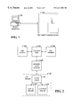
- FIG. 1 illustrates a systems operations console coupled to a host data processing system
- FIG. 2 is a functional block diagram illustrating software components used to interface, operate, and manage host 102 , in accordance with one embodiment of the invention
- FIG. 3 is a flowchart of a process for updating persistent data in accordance with one embodiment of the invention.
- FIG. 4 is a flowchart of a process that implements a start method in a persistent object controller
- FIG. 5A is a flowchart of a process for committing persistent data objects
- FIG. 5B illustrates a current persistent data set, a control record, and working and committed data sets as related initially at time t i , after a first commit at time t commit1 , and after a second commit at time t commit2 ;
- FIG. 6 is a flowchart of an example process for recovering persistent data
- FIG. 7 is an object model diagram that illustrates class relationships for managing persistent data.
- FIGS. 8A, 8 B, and 8 C illustrate the interrelationships between persistent data objects, indices, saved indices, and saved data of persistent data objects.
- the present invention is believed to be applicable to a variety of object oriented applications.
- the invention has been found to be particularly applicable and beneficial for persisting data objects related to operations and configuration information of a large scale data processing system. While the present invention is not so limited, an appreciation of the present invention is presented by way of an embodiment including a systems operations console and a host data processing system.
- FIG. 1 illustrates a systems operations console coupled to a host data processing system.
- Host system 102 is a 2200 Series data processing system, for example, and includes configurable computing resources such as memory subsystems, mass storage subsystems, communication channels, and multiple instruction processors.
- the computing resources are typically managed by the host operating system (not shown) and configured for availability by a system operator via operations console 104 . It will be appreciated that the platform on which the operations console is implemented can be built within the cabinet of host 102 or implemented in a separate cabinet as shown.
- operations console 104 an operator can partition host 102 into multiple data processing systems, enable or disable access to storage systems, and activate or deactivate instruction processors, for example. Since operations console 104 oversees the various partitions and configuration information of host 102 and is implemented on a separate computing platform, the operations console must ensure that the configuration information will persist between an unexpected shutdown of the console and restarting the console.
- FIG. 2 is a functional block diagram illustrating software components used to interface, operate, and manage host 102 , in accordance with one embodiment of the invention.
- the software components include user interface 122 , operations logic 124 , host interface 126 , and persistent object controller 128 .
- Various software technologies can be used to implement the different components.
- an object-oriented language may be suitable for user interface 122 , operations logic 124 , and persistent object controller 128
- a third generation language, such as C may be suitable for host interface 126 .
- User interface 122 and operations logic 124 provide the functionality that enables the operator to manage the operations of host 102 .
- User interface 122 may be implemented as a graphical user interface, for example, and operations logic 124 includes the rules that govern operation of system 102 .
- operations logic 124 restricts the operator to configuring valid hardware combinations.
- Host interface 126 is conventional software that provides communication between operations logic 124 and the operating system of host 102 .
- persistent object controller 128 is implemented in C++ and manages information that must persist relative to the configuration of host 102 .
- the persistent configuration information may include which processors, communications channels, mass storage devices, and input/output channels are associated with which partition.
- Class definitions support extensibility of the configuration data to persist, and persistent object controller controls and tracks which data is persistent, along with committing data to persistent storage and recovering persistent data when necessary.
- Updates to persistent data as stored in computer memory of console 104 is performed by the software component responsible for the data, for example, operations logic 124 .
- Persistent object controller 128 handles committing the updates to data storage element 130 .
- storage element 130 is a conventional magnetic disk of the type generally used with microcomputers. Those skilled in the art will recognize other suitable media. The reliability of storage element 130 is commensurate with the nature of the persistent data. For example in a systems operations environment, the storage element should be very reliable since a failure could have a far-reaching impact on applications hosted by system 102 .
- Persistent object controller 128 uses commit and recover procedures, as initiated by operations logic 124 , for example, to store and recover persistent data to and from storage element 130 . All persistent data objects are registered with persistent object controller 128 and defined to be part of a persistent data set. After an application such as operations logic 124 has updated the persistent data set and determined that the data can be committed, a call is made to a commit method that is implemented in persistent object controller 128 . The commit method writes the persistent data set to working data set 132 , and then switches working data set 132 and committed data set 134 . In other words, at commit time the working data set becomes the committed data set and the committed data set becomes the working data set. The switch is accomplished in one embodiment by updating control record 136 with new references to the working and committed data sets.
- FIG. 3 is a flowchart of a process for updating persistent data in accordance with one embodiment of the invention.
- the process is performed by software, for example, operations logic 124 having persistent data registered with persistent object controller 128 .
- the process generally follows a transaction-oriented procedure for committing data at the appropriate time.
- a start method as provided by persistent object controller 128 is initiated by the calling software.
- the start method generally associates a transaction object with the thread of the calling software.
- the transaction object is used to track the persistent data objects locked by the transaction.
- the persistent data is updated in computer memory, and the commit procedure of the persistent object controller is initiated at step 166 .
- the commit procedure generally entails writing the updated persistent data from memory to mass storage, and maintaining working and committed versions of the persistent data.
- FIG. 4 is a flowchart of a process that implements a start method in persistent object controller 128 in accordance with one embodiment of the invention.
- the start method coordinates the association of transaction objects with threads that are updating persistent data.
- Each thread that initiates the start method has associated therewith a transaction object.
- the start method of the persistent object controller searches for the thread of the calling application in a thread table (not shown).
- the thread table indicates which threads presently have transaction objects associated therewith. If the thread is found, decision step 174 directs control to step 176 to obtain the associated transaction object.
- the start-count that is associated with the thread is incremented. The start-count is used to track by thread the number of transactions involving persistent data that are in process and incomplete. When a thread initiates committing persistent data, the persistent data is written to persistent storage only when there are no transactions currently in process by the thread.
- step 180 If the thread of the calling application does not yet have an associated transaction object, control is directed to step 180 where a new transaction object is instantiated. At step 182 , a new entry is added to the transaction map (not shown).
- the transaction map (as embodied in the Trans Map attribute of the Persistent Controller object of FIG. 7) is a table having the thread identifier as the key and the transaction object pointer as the value.
- the transaction map is used to find a thread's transaction object on a lock/unlock call without having to pass the transaction object in the call.
- the thread identifier is obtained from the operating system and is used as the key into the transaction map to obtain the pointer to the transaction object. Control is returned to the calling application at step 184 .
- FIG. 5A is a flowchart of a process for committing persistent data objects in accordance with one embodiment of the invention.
- the commit process generally writes the updated persistent data to working data set 132 and updates control record 136 to switch references between working data set 132 and committed data set 134 .
- the persistent data objects may optionally be stored redundantly. That is, duplicate versions of working data set 132 and committed data set 134 are maintained if a “redundancy” parameter is associated with the persistent data objects. Thus, if redundancy is specified, decision step 210 directs control to step 212 where the current persistent data is written to a redundant working data set. It will be appreciated that the data storage element on which the redundant data is stored may be the same as or separate from data storage element 130 , depending up on the level of data protection desired.
- control record is updated.
- the control record includes references to working data set 132 and committed data set 134 , which are switched after working data set 132 has been written.
- the former working data set is the present committed data set
- the former committed data set is the current working data set.
- the working and committed data sets are maintained to preserve data integrity in the event console 104 fails while writing to working data set 132 .
- decision step 216 directs control to step 218 where the redundant control record is updated.
- the references to the redundant working data set and redundant committed data set are switched, whereby the former redundant working data set becomes the current redundant committed data set and the former redundant committed data set becomes the current redundant working data set.
- control record from console 104 is written to control record 136 of storage element 130 . If redundancy is specified (decision step 222 ), the redundant control record is also written to a storage element (step 224 ). Control is returned to the calling application at step 226 .
- the method for committing and restoring persistent data is handled by persistent object controller 128 such that pointers between objects can be recreated when a recovery is done from storage element 130 .
- objects are registered for persistence they are assigned an index.
- index is saved instead.
- pointers When it is necessary to recreate the objects from persistent storage empty versions of all objects are created. These objects are then populated. As pointers are restored the index is used to create a pointer to the correct object.
- FIG. 5B illustrates a current persistent data set, a control record, and working and committed data sets as related initially at time t i , after a first commit at time t commit1 and after a second commit at time t commit2 .
- control record 136 references data set 262 as the working data set and data set 264 as the committed data set.
- Current data set 266 represents the persistent data as present in the memory of console 104 .
- the current persistent data set 266 is written to data set 262 , which then becomes the committed data set, and data set 264 becomes the working data set.
- current persistent data set 266 is written to data set 264 , which becomes the committed data set, and data set 262 becomes the working data set.
- FIG. 6 is a flowchart of an example process for recovering persistent data in accordance with one embodiment of the invention.
- control record 136 is read from storage element 130
- the redundant control is read if redundancy is specified.
- control record 136 and in the redundant control record are compared at step 186 , and the committed data set that is referenced by the control record having the later timestamp is selected for restoration.
- the committed data set selected at step 286 is read from storage element 130 , and at step 290 , the current data set is updated using data from the selected committed data set. Control is returned the calling application at step 292 .
- FIG. 7 is an object model diagram that illustrates class relationships for managing persistent data in accordance with one embodiment of the invention.
- Objects of the Persistent Data class inherit from the Serializable class.
- Persistent objects inherit from an object that allows the capability of persistence. It is, therefore possible to create different instances of a particular object some of which are persistent and some of which are not. The act of registering an object makes it persistent when the transaction completes.
- Objects for which persistence is desired are allowed to contain both persistent and non-persistent data.
- the Load and Store methods of the Serializable class provide the means to make this selection. These methods provide the selection of data and its transition to or from a serial stream.
- the Persistent Data class from which all persistent objects inherit declares, as pure virtual, the load and store methods (for saving and restoring data). As shown in the object model diagram, it is the Serializable class that declares, as pure virtual, the load and store methods. All persistent objects are forced to implement these methods because they indirectly inherit from the Serializable class. Persistent objects inherit from the Persistent Data class which inherits from the Serializable class.
- the persistent controller will call load and store on the objects of the Persistent Data class, but the actual implementation of these methods is in the objects that inherit from the Persistent Data class.
- a default constructor When persistent data is recovered, a default constructor (no data supplied) is used to create each object in the file and then call the load method on each object so that the object can load its data. For committing persistent data, each object that has been modified during the transaction (identified using the list in the transaction object) is called to commit its data to the persistent stream (buffer that is written to the persistent file). The method called is the store method.
- Read Lock Count count of read locks outstanding. Read Lock Count allows for nested locking (e.g. lock, lock, unlock, unlock). A count >0 locks object from being used by another thread (transaction).
- Write Lock Count count of write locks outstanding. Count allows for nested locking (e.g. lock, lock, unlock, unlock). A count >0 locks object from being used by another thread (transaction). When this count is >0 we will write this object (call the store method) during commit.
- Index index value assigned to this object instance.
- Lock sets (increments) lock count. Parameter indicates read or write. If another thread has the object locked, then this causes a wait.
- Register register this object instance with the persistent subsystem. This method gets the index value for the object and locks the object for write.
- Deregister calls the persistent subsystem to mark the object as being deregistered and locks the object for write. The object will be removed from persistence on the next commit.
- application data desired to be persistent are implemented as objects that inherit from the Persistent Data class.
- Free stack vector of freed index values.
- File 1 and file 2 file handles for the two persistent files (local and redundant)
- Start starts a transaction. If the thread already has a transaction, this increments the start count on the transaction. If not, then a new transaction object is allocated with a count of 1.
- Recover recovers persistent objects from the persistent file. This is used at system startup/initialization to re-create persistent objects.
- Remove object removes an object from the transaction's object list. Called because an unlock has been done which resulted in 0 locks left up.
- Add object adds an object to the transaction's object list.
- FIGS. 8A, 8 B, and 8 C illustrate the interrelationships between persistent data objects, indices, saved indices, and saved data of persistent data objects.
- FIG. 8A shows a memory 310 having example persistent data objects 312 , 314 , and 316 . While not shown, it will be appreciated that each of persistent data objects 312 , 314 , and 316 may include additional attributes that reference the data for which persistence is desired.
- Object 312 is stored at memory address 111111
- object 314 is stored at memory address 333333
- object 316 is stored at memory address 222222 , for example.
- Each persistent data object includes an attribute that references one or more related persistent data objects.
- object 312 has an attribute, the memory address 333333 , for referencing the related data object 314
- object 314 references the data object at address 222222 .
- These memory references indicate class relationships between the persistent data objects.
- Each of persistent data objects 312 , 314 , and 316 also includes an index value for referencing an entry in persistent controller object map 320 of FIG. 8 B.
- Each entry in map 320 is associated with a persistent data object and includes the memory address of the persistent data object and the persistent storage address at which the persistent data object is stored.
- the persistent storage address is, for example, a file relative offset into persistent data file 322 of FIG. 8 C.
- the persistent data object of at memory address 333333 is stored in file 322 at offset 32
- the persistent data object of at memory address 222222 is stored in file 322 at offset 47
- the persistent data object of at memory address 111111 is stored in file 322 at offset 60 .
- Each of the persistent data objects stored in file 322 includes its associated index, along with attribute values that reference related persistent data objects (if there are related objects).
- the persistent data object from memory address 111111 has the index value 5 and is stored at offset 60 .
- Persistent data object 324 at offset 60 includes two attributes. The first attribute is the index value 5 that is associated with the persistent data object, and the second attribute references the index of a related persistent data object.
- the attribute value 2 is the index attribute of persistent data object 314 which is pointed to by data object 314 .
- data object 326 stored at file offset 32 and having index value 2 is associated with persistent data object 314 and has an attribute value 4 which references the index of persistent data object 316 . Since object 316 has no related objects, there is attribute value. Storing the indices of the related persistent data objects provides efficient reconstruction of the object relationships when data is recovered from persistent data file 322 .
- the present invention provides, among other aspects, a method for persisting data objects without incurring the overhead of an object oriented database management system.
- Other aspects and embodiments of the present invention will be apparent to those skilled in the art from consideration of the specification and practice of the invention disclosed herein. It is intended that the specification and illustrated embodiments be considered as examples only, with a true scope and spirit of the invention being indicated by the following claims.
Abstract
Description
Claims (20)
Priority Applications (5)
| Application Number | Priority Date | Filing Date | Title |
|---|---|---|---|
| US09/444,484 US6411954B1 (en) | 1999-11-19 | 1999-11-19 | Method and apparatus for persisting object oriented data |
| JP2001539104A JP2003515213A (en) | 1999-11-19 | 2000-11-14 | Method and apparatus for persisting object-oriented data |
| PCT/US2000/031154 WO2001037078A2 (en) | 1999-11-19 | 2000-11-14 | Method and apparatus for persisting object oriented data |
| EP00977197A EP1234229B1 (en) | 1999-11-19 | 2000-11-14 | Method and apparatus for persisting object oriented data |
| DE60009548T DE60009548T2 (en) | 1999-11-19 | 2000-11-14 | METHOD AND DEVICE FOR PERSISTING OBJECT-ORIENTED DATA |
Applications Claiming Priority (1)
| Application Number | Priority Date | Filing Date | Title |
|---|---|---|---|
| US09/444,484 US6411954B1 (en) | 1999-11-19 | 1999-11-19 | Method and apparatus for persisting object oriented data |
Publications (1)
| Publication Number | Publication Date |
|---|---|
| US6411954B1 true US6411954B1 (en) | 2002-06-25 |
Family
ID=23765097
Family Applications (1)
| Application Number | Title | Priority Date | Filing Date |
|---|---|---|---|
| US09/444,484 Expired - Lifetime US6411954B1 (en) | 1999-11-19 | 1999-11-19 | Method and apparatus for persisting object oriented data |
Country Status (5)
| Country | Link |
|---|---|
| US (1) | US6411954B1 (en) |
| EP (1) | EP1234229B1 (en) |
| JP (1) | JP2003515213A (en) |
| DE (1) | DE60009548T2 (en) |
| WO (1) | WO2001037078A2 (en) |
Cited By (9)
| Publication number | Priority date | Publication date | Assignee | Title |
|---|---|---|---|---|
| US20020152423A1 (en) * | 2001-02-05 | 2002-10-17 | Mccabe Harry | Persistent session and data in transparently distributed objects |
| US20040015829A1 (en) * | 2001-06-01 | 2004-01-22 | Ward Mullins | System, method and software for creating, maintaining, navigating or manipulating complex data objects and their data relationships |
| US20040172420A1 (en) * | 2001-07-03 | 2004-09-02 | Dahms John F A | System and method of object-oriented persistence |
| US20040204778A1 (en) * | 2003-01-06 | 2004-10-14 | Harish Lalapeth | Method for persisting SNMP MIB data in files |
| US20100153397A1 (en) * | 2000-10-13 | 2010-06-17 | Miosoft Corporation | Maintaining a relationship between two different items of data |
| US20100191705A1 (en) * | 2000-10-13 | 2010-07-29 | Miosoft Corporation, A Delaware Corporation | Persistent data storage techniques |
| US9442862B2 (en) | 2013-01-21 | 2016-09-13 | International Business Machines Corporation | Polymorph table with shared columns |
| US10783136B1 (en) * | 2017-02-28 | 2020-09-22 | Virtuozzo International Gmbh | Management of garbage data in distributed systems |
| US11115486B2 (en) * | 2018-08-08 | 2021-09-07 | Microsoft Technology Licensing, Llc | Data re-use across documents |
Citations (5)
| Publication number | Priority date | Publication date | Assignee | Title |
|---|---|---|---|---|
| US5377350A (en) * | 1993-04-30 | 1994-12-27 | International Business Machines Corporation | System for cooperative communication between local object managers to provide verification for the performance of remote calls by object messages |
| US5751958A (en) * | 1995-06-30 | 1998-05-12 | Peoplesoft, Inc. | Allowing inconsistency in a distributed client-server application |
| US5884327A (en) * | 1996-09-25 | 1999-03-16 | International Business Machines Corporation | System, method and program for performing two-phase commit with a coordinator that performs no logging |
| US6192408B1 (en) * | 1997-09-26 | 2001-02-20 | Emc Corporation | Network file server sharing local caches of file access information in data processors assigned to respective file systems |
| US6275953B1 (en) * | 1997-09-26 | 2001-08-14 | Emc Corporation | Recovery from failure of a data processor in a network server |
Family Cites Families (5)
| Publication number | Priority date | Publication date | Assignee | Title |
|---|---|---|---|---|
| US5819306A (en) * | 1995-02-14 | 1998-10-06 | General Magic | Shadow mechanism for a modifiable object oriented system |
| US5960445A (en) * | 1996-04-24 | 1999-09-28 | Sony Corporation | Information processor, method of updating a program and information processing system |
| JPH10287027A (en) * | 1997-02-14 | 1998-10-27 | Canon Inc | Printer apparatus and method for protecting information at printer apparatus |
| DE19720990A1 (en) * | 1997-05-20 | 1998-11-26 | Alsthom Cge Alcatel | Program-controlled setup with the possibility of reloading and switching to the second operating system without program interruption |
| US6324411B1 (en) * | 1997-05-20 | 2001-11-27 | Telefonaktiebolaget Lm Ericsson (Publ) | Background software loading in cellular telecommunication systems |
-
1999
- 1999-11-19 US US09/444,484 patent/US6411954B1/en not_active Expired - Lifetime
-
2000
- 2000-11-14 EP EP00977197A patent/EP1234229B1/en not_active Expired - Lifetime
- 2000-11-14 JP JP2001539104A patent/JP2003515213A/en active Pending
- 2000-11-14 DE DE60009548T patent/DE60009548T2/en not_active Expired - Fee Related
- 2000-11-14 WO PCT/US2000/031154 patent/WO2001037078A2/en active IP Right Grant
Patent Citations (5)
| Publication number | Priority date | Publication date | Assignee | Title |
|---|---|---|---|---|
| US5377350A (en) * | 1993-04-30 | 1994-12-27 | International Business Machines Corporation | System for cooperative communication between local object managers to provide verification for the performance of remote calls by object messages |
| US5751958A (en) * | 1995-06-30 | 1998-05-12 | Peoplesoft, Inc. | Allowing inconsistency in a distributed client-server application |
| US5884327A (en) * | 1996-09-25 | 1999-03-16 | International Business Machines Corporation | System, method and program for performing two-phase commit with a coordinator that performs no logging |
| US6192408B1 (en) * | 1997-09-26 | 2001-02-20 | Emc Corporation | Network file server sharing local caches of file access information in data processors assigned to respective file systems |
| US6275953B1 (en) * | 1997-09-26 | 2001-08-14 | Emc Corporation | Recovery from failure of a data processor in a network server |
Cited By (16)
| Publication number | Priority date | Publication date | Assignee | Title |
|---|---|---|---|---|
| US8935225B2 (en) | 2000-10-13 | 2015-01-13 | Miosoft Corporation | Persistent data storage techniques |
| US9830348B2 (en) | 2000-10-13 | 2017-11-28 | Miosoft Corporation | Persistent data storage techniques |
| US9189536B2 (en) * | 2000-10-13 | 2015-11-17 | Miosoft Corporation | Maintaining a relationship between two different items of data |
| US20100153397A1 (en) * | 2000-10-13 | 2010-06-17 | Miosoft Corporation | Maintaining a relationship between two different items of data |
| US20100191705A1 (en) * | 2000-10-13 | 2010-07-29 | Miosoft Corporation, A Delaware Corporation | Persistent data storage techniques |
| US8489567B2 (en) | 2000-10-13 | 2013-07-16 | Microsoft Corporation | Persistent data storage techniques |
| US7146532B2 (en) * | 2001-02-05 | 2006-12-05 | Affiniti, Inc. | Persistent session and data in transparently distributed objects |
| US20020152423A1 (en) * | 2001-02-05 | 2002-10-17 | Mccabe Harry | Persistent session and data in transparently distributed objects |
| US20040015829A1 (en) * | 2001-06-01 | 2004-01-22 | Ward Mullins | System, method and software for creating, maintaining, navigating or manipulating complex data objects and their data relationships |
| US7043481B2 (en) * | 2001-06-01 | 2006-05-09 | Thought, Inc. | System, method and software for creating, maintaining, navigating or manipulating complex data objects and their data relationships |
| US8019789B2 (en) * | 2001-07-03 | 2011-09-13 | Research In Motion Limited | System and method of object-oriented persistence |
| US20040172420A1 (en) * | 2001-07-03 | 2004-09-02 | Dahms John F A | System and method of object-oriented persistence |
| US20040204778A1 (en) * | 2003-01-06 | 2004-10-14 | Harish Lalapeth | Method for persisting SNMP MIB data in files |
| US9442862B2 (en) | 2013-01-21 | 2016-09-13 | International Business Machines Corporation | Polymorph table with shared columns |
| US10783136B1 (en) * | 2017-02-28 | 2020-09-22 | Virtuozzo International Gmbh | Management of garbage data in distributed systems |
| US11115486B2 (en) * | 2018-08-08 | 2021-09-07 | Microsoft Technology Licensing, Llc | Data re-use across documents |
Also Published As
| Publication number | Publication date |
|---|---|
| DE60009548D1 (en) | 2004-05-06 |
| DE60009548T2 (en) | 2005-02-24 |
| JP2003515213A (en) | 2003-04-22 |
| EP1234229B1 (en) | 2004-03-31 |
| WO2001037078A3 (en) | 2002-05-10 |
| WO2001037078A2 (en) | 2001-05-25 |
| EP1234229A2 (en) | 2002-08-28 |
Similar Documents
| Publication | Publication Date | Title |
|---|---|---|
| Verhofstad | Recovery techniques for database systems | |
| US7543181B2 (en) | Recovery from failures within data processing systems | |
| US6895529B2 (en) | Rebuilding “in-doubt” states reliably after multiple system failures in a data processing system performing two-phase transaction processing | |
| US6061769A (en) | Data set backup in a shared environment | |
| US20040215998A1 (en) | Recovery from failures within data processing systems | |
| US5408652A (en) | Method and apparatus for heterogenous database access by generating different access procedures for different database data structures | |
| US5151987A (en) | Recovery objects in an object oriented computing environment | |
| US5437026A (en) | Removing uncommitted changes made to stored data by a database management system | |
| US20070283111A1 (en) | Method and System for Transporting Data Content on a Storage Area Network | |
| KR100233178B1 (en) | Method and system for updating mass storage device configuration records | |
| US5740434A (en) | System for maintenance of database integrity | |
| US5745905A (en) | Method for optimizing space in a memory having backup and database areas | |
| JPH0760420B2 (en) | "Apparatus and method for dynamically reconfiguring I / O unit" | |
| US8108356B2 (en) | Method for recovering data in a storage system | |
| US6411954B1 (en) | Method and apparatus for persisting object oriented data | |
| KR100819022B1 (en) | Managing a relationship between one target volume and one source volume | |
| US5999935A (en) | Tail compression of a sparse log stream of a multisystem environment | |
| Härder et al. | Processing and transaction concepts for cooperation of engineering workstations and a database server | |
| US6125393A (en) | System of compressing the tail of a sparse log stream of a multisystem environment | |
| Gray et al. | The recovery manager of a data management system | |
| US6092084A (en) | One system of a multisystem environment taking over log entries owned by another system | |
| US6076095A (en) | Method of one system of a multisystem environment taking over log entries owned by another system | |
| US7685122B1 (en) | Facilitating suspension of batch application program access to shared IMS resources | |
| EP0834128B1 (en) | Data set backup in a shared environment | |
| JP2574532B2 (en) | Resource management method in fault tolerant system |
Legal Events
| Date | Code | Title | Description |
|---|---|---|---|
| AS | Assignment |
Owner name: UNISYS CORPORATION, MINNESOTA Free format text: ASSIGNMENT OF ASSIGNORS INTEREST;ASSIGNORS:ROFFE, JAMES (NMI);STAFFORD, EDWARD (NMI);REEL/FRAME:010403/0543 Effective date: 19991021 |
|
| FEPP | Fee payment procedure |
Free format text: PAYOR NUMBER ASSIGNED (ORIGINAL EVENT CODE: ASPN); ENTITY STATUS OF PATENT OWNER: LARGE ENTITY |
|
| STCF | Information on status: patent grant |
Free format text: PATENTED CASE |
|
| FPAY | Fee payment |
Year of fee payment: 4 |
|
| AS | Assignment |
Owner name: UNISYS CORPORATION, PENNSYLVANIA Free format text: RELEASE BY SECURED PARTY;ASSIGNOR:CITIBANK, N.A.;REEL/FRAME:023312/0044 Effective date: 20090601 Owner name: UNISYS HOLDING CORPORATION, DELAWARE Free format text: RELEASE BY SECURED PARTY;ASSIGNOR:CITIBANK, N.A.;REEL/FRAME:023312/0044 Effective date: 20090601 Owner name: UNISYS CORPORATION,PENNSYLVANIA Free format text: RELEASE BY SECURED PARTY;ASSIGNOR:CITIBANK, N.A.;REEL/FRAME:023312/0044 Effective date: 20090601 Owner name: UNISYS HOLDING CORPORATION,DELAWARE Free format text: RELEASE BY SECURED PARTY;ASSIGNOR:CITIBANK, N.A.;REEL/FRAME:023312/0044 Effective date: 20090601 |
|
| AS | Assignment |
Owner name: UNISYS CORPORATION, PENNSYLVANIA Free format text: RELEASE BY SECURED PARTY;ASSIGNOR:CITIBANK, N.A.;REEL/FRAME:023263/0631 Effective date: 20090601 Owner name: UNISYS HOLDING CORPORATION, DELAWARE Free format text: RELEASE BY SECURED PARTY;ASSIGNOR:CITIBANK, N.A.;REEL/FRAME:023263/0631 Effective date: 20090601 Owner name: UNISYS CORPORATION,PENNSYLVANIA Free format text: RELEASE BY SECURED PARTY;ASSIGNOR:CITIBANK, N.A.;REEL/FRAME:023263/0631 Effective date: 20090601 Owner name: UNISYS HOLDING CORPORATION,DELAWARE Free format text: RELEASE BY SECURED PARTY;ASSIGNOR:CITIBANK, N.A.;REEL/FRAME:023263/0631 Effective date: 20090601 |
|
| AS | Assignment |
Owner name: DEUTSCHE BANK TRUST COMPANY AMERICAS, AS COLLATERA Free format text: PATENT SECURITY AGREEMENT (PRIORITY LIEN);ASSIGNOR:UNISYS CORPORATION;REEL/FRAME:023355/0001 Effective date: 20090731 |
|
| AS | Assignment |
Owner name: DEUTSCHE BANK TRUST COMPANY AMERICAS, AS COLLATERA Free format text: PATENT SECURITY AGREEMENT (JUNIOR LIEN);ASSIGNOR:UNISYS CORPORATION;REEL/FRAME:023364/0098 Effective date: 20090731 |
|
| FPAY | Fee payment |
Year of fee payment: 8 |
|
| AS | Assignment |
Owner name: GENERAL ELECTRIC CAPITAL CORPORATION, AS AGENT, IL Free format text: SECURITY AGREEMENT;ASSIGNOR:UNISYS CORPORATION;REEL/FRAME:026509/0001 Effective date: 20110623 |
|
| AS | Assignment |
Owner name: UNISYS CORPORATION, PENNSYLVANIA Free format text: RELEASE BY SECURED PARTY;ASSIGNOR:DEUTSCHE BANK TRUST COMPANY;REEL/FRAME:030004/0619 Effective date: 20121127 |
|
| AS | Assignment |
Owner name: UNISYS CORPORATION, PENNSYLVANIA Free format text: RELEASE BY SECURED PARTY;ASSIGNOR:DEUTSCHE BANK TRUST COMPANY AMERICAS, AS COLLATERAL TRUSTEE;REEL/FRAME:030082/0545 Effective date: 20121127 |
|
| FPAY | Fee payment |
Year of fee payment: 12 |
|
| AS | Assignment |
Owner name: WELLS FARGO BANK, NATIONAL ASSOCIATION, AS COLLATE Free format text: PATENT SECURITY AGREEMENT;ASSIGNOR:UNISYS CORPORATION;REEL/FRAME:042354/0001 Effective date: 20170417 Owner name: WELLS FARGO BANK, NATIONAL ASSOCIATION, AS COLLATERAL TRUSTEE, NEW YORK Free format text: PATENT SECURITY AGREEMENT;ASSIGNOR:UNISYS CORPORATION;REEL/FRAME:042354/0001 Effective date: 20170417 |
|
| AS | Assignment |
Owner name: JPMORGAN CHASE BANK, N.A., AS ADMINISTRATIVE AGENT, ILLINOIS Free format text: SECURITY INTEREST;ASSIGNOR:UNISYS CORPORATION;REEL/FRAME:044144/0081 Effective date: 20171005 Owner name: JPMORGAN CHASE BANK, N.A., AS ADMINISTRATIVE AGENT Free format text: SECURITY INTEREST;ASSIGNOR:UNISYS CORPORATION;REEL/FRAME:044144/0081 Effective date: 20171005 |
|
| AS | Assignment |
Owner name: UNISYS CORPORATION, PENNSYLVANIA Free format text: RELEASE BY SECURED PARTY;ASSIGNOR:WELLS FARGO BANK, NATIONAL ASSOCIATION (SUCCESSOR TO GENERAL ELECTRIC CAPITAL CORPORATION);REEL/FRAME:044416/0358 Effective date: 20171005 |
|
| AS | Assignment |
Owner name: UNISYS CORPORATION, PENNSYLVANIA Free format text: RELEASE BY SECURED PARTY;ASSIGNOR:WELLS FARGO BANK, NATIONAL ASSOCIATION;REEL/FRAME:054231/0496 Effective date: 20200319 |