US6398342B1 - Open jet compensation during multi-pass printing - Google Patents
Open jet compensation during multi-pass printing Download PDFInfo
- Publication number
- US6398342B1 US6398342B1 US09/929,196 US92919601A US6398342B1 US 6398342 B1 US6398342 B1 US 6398342B1 US 92919601 A US92919601 A US 92919601A US 6398342 B1 US6398342 B1 US 6398342B1
- Authority
- US
- United States
- Prior art keywords
- jet
- mask
- jets
- replacement
- Prior art date
- Legal status (The legal status is an assumption and is not a legal conclusion. Google has not performed a legal analysis and makes no representation as to the accuracy of the status listed.)
- Expired - Lifetime
Links
- 238000007639 printing Methods 0.000 title claims description 50
- 230000002950 deficient Effects 0.000 abstract description 27
- 238000000034 method Methods 0.000 abstract description 23
- 230000001174 ascending effect Effects 0.000 description 7
- 238000004581 coalescence Methods 0.000 description 7
- 230000008569 process Effects 0.000 description 7
- 230000015556 catabolic process Effects 0.000 description 5
- 238000006731 degradation reaction Methods 0.000 description 5
- 239000007787 solid Substances 0.000 description 4
- 238000010304 firing Methods 0.000 description 2
- 238000007641 inkjet printing Methods 0.000 description 2
- 230000007704 transition Effects 0.000 description 2
- 241001522296 Erithacus rubecula Species 0.000 description 1
- 239000003086 colorant Substances 0.000 description 1
- 230000000295 complement effect Effects 0.000 description 1
- 238000010586 diagram Methods 0.000 description 1
- 238000005516 engineering process Methods 0.000 description 1
- 238000001914 filtration Methods 0.000 description 1
- 230000006870 function Effects 0.000 description 1
- 239000007788 liquid Substances 0.000 description 1
- 230000007246 mechanism Effects 0.000 description 1
- 230000004048 modification Effects 0.000 description 1
- 238000012986 modification Methods 0.000 description 1
- 229920006395 saturated elastomer Polymers 0.000 description 1
Images


Classifications
-
- B—PERFORMING OPERATIONS; TRANSPORTING
- B41—PRINTING; LINING MACHINES; TYPEWRITERS; STAMPS
- B41J—TYPEWRITERS; SELECTIVE PRINTING MECHANISMS, i.e. MECHANISMS PRINTING OTHERWISE THAN FROM A FORME; CORRECTION OF TYPOGRAPHICAL ERRORS
- B41J2/00—Typewriters or selective printing mechanisms characterised by the printing or marking process for which they are designed
- B41J2/005—Typewriters or selective printing mechanisms characterised by the printing or marking process for which they are designed characterised by bringing liquid or particles selectively into contact with a printing material
- B41J2/01—Ink jet
- B41J2/015—Ink jet characterised by the jet generation process
- B41J2/04—Ink jet characterised by the jet generation process generating single droplets or particles on demand
- B41J2/045—Ink jet characterised by the jet generation process generating single droplets or particles on demand by pressure, e.g. electromechanical transducers
- B41J2/04501—Control methods or devices therefor, e.g. driver circuits, control circuits
- B41J2/0451—Control methods or devices therefor, e.g. driver circuits, control circuits for detecting failure, e.g. clogging, malfunctioning actuator
-
- B—PERFORMING OPERATIONS; TRANSPORTING
- B41—PRINTING; LINING MACHINES; TYPEWRITERS; STAMPS
- B41J—TYPEWRITERS; SELECTIVE PRINTING MECHANISMS, i.e. MECHANISMS PRINTING OTHERWISE THAN FROM A FORME; CORRECTION OF TYPOGRAPHICAL ERRORS
- B41J2/00—Typewriters or selective printing mechanisms characterised by the printing or marking process for which they are designed
- B41J2/005—Typewriters or selective printing mechanisms characterised by the printing or marking process for which they are designed characterised by bringing liquid or particles selectively into contact with a printing material
- B41J2/01—Ink jet
- B41J2/015—Ink jet characterised by the jet generation process
- B41J2/04—Ink jet characterised by the jet generation process generating single droplets or particles on demand
- B41J2/045—Ink jet characterised by the jet generation process generating single droplets or particles on demand by pressure, e.g. electromechanical transducers
- B41J2/04501—Control methods or devices therefor, e.g. driver circuits, control circuits
- B41J2/04541—Specific driving circuit
-
- B—PERFORMING OPERATIONS; TRANSPORTING
- B41—PRINTING; LINING MACHINES; TYPEWRITERS; STAMPS
- B41J—TYPEWRITERS; SELECTIVE PRINTING MECHANISMS, i.e. MECHANISMS PRINTING OTHERWISE THAN FROM A FORME; CORRECTION OF TYPOGRAPHICAL ERRORS
- B41J2/00—Typewriters or selective printing mechanisms characterised by the printing or marking process for which they are designed
- B41J2/005—Typewriters or selective printing mechanisms characterised by the printing or marking process for which they are designed characterised by bringing liquid or particles selectively into contact with a printing material
- B41J2/01—Ink jet
- B41J2/015—Ink jet characterised by the jet generation process
- B41J2/04—Ink jet characterised by the jet generation process generating single droplets or particles on demand
- B41J2/045—Ink jet characterised by the jet generation process generating single droplets or particles on demand by pressure, e.g. electromechanical transducers
- B41J2/04501—Control methods or devices therefor, e.g. driver circuits, control circuits
- B41J2/04543—Block driving
-
- B—PERFORMING OPERATIONS; TRANSPORTING
- B41—PRINTING; LINING MACHINES; TYPEWRITERS; STAMPS
- B41J—TYPEWRITERS; SELECTIVE PRINTING MECHANISMS, i.e. MECHANISMS PRINTING OTHERWISE THAN FROM A FORME; CORRECTION OF TYPOGRAPHICAL ERRORS
- B41J2/00—Typewriters or selective printing mechanisms characterised by the printing or marking process for which they are designed
- B41J2/005—Typewriters or selective printing mechanisms characterised by the printing or marking process for which they are designed characterised by bringing liquid or particles selectively into contact with a printing material
- B41J2/01—Ink jet
- B41J2/015—Ink jet characterised by the jet generation process
- B41J2/04—Ink jet characterised by the jet generation process generating single droplets or particles on demand
- B41J2/045—Ink jet characterised by the jet generation process generating single droplets or particles on demand by pressure, e.g. electromechanical transducers
- B41J2/04501—Control methods or devices therefor, e.g. driver circuits, control circuits
- B41J2/0457—Power supply level being detected or varied
-
- B—PERFORMING OPERATIONS; TRANSPORTING
- B41—PRINTING; LINING MACHINES; TYPEWRITERS; STAMPS
- B41J—TYPEWRITERS; SELECTIVE PRINTING MECHANISMS, i.e. MECHANISMS PRINTING OTHERWISE THAN FROM A FORME; CORRECTION OF TYPOGRAPHICAL ERRORS
- B41J2/00—Typewriters or selective printing mechanisms characterised by the printing or marking process for which they are designed
- B41J2/005—Typewriters or selective printing mechanisms characterised by the printing or marking process for which they are designed characterised by bringing liquid or particles selectively into contact with a printing material
- B41J2/01—Ink jet
- B41J2/015—Ink jet characterised by the jet generation process
- B41J2/04—Ink jet characterised by the jet generation process generating single droplets or particles on demand
- B41J2/045—Ink jet characterised by the jet generation process generating single droplets or particles on demand by pressure, e.g. electromechanical transducers
- B41J2/04501—Control methods or devices therefor, e.g. driver circuits, control circuits
- B41J2/0458—Control methods or devices therefor, e.g. driver circuits, control circuits controlling heads based on heating elements forming bubbles
-
- B—PERFORMING OPERATIONS; TRANSPORTING
- B41—PRINTING; LINING MACHINES; TYPEWRITERS; STAMPS
- B41J—TYPEWRITERS; SELECTIVE PRINTING MECHANISMS, i.e. MECHANISMS PRINTING OTHERWISE THAN FROM A FORME; CORRECTION OF TYPOGRAPHICAL ERRORS
- B41J2/00—Typewriters or selective printing mechanisms characterised by the printing or marking process for which they are designed
- B41J2/005—Typewriters or selective printing mechanisms characterised by the printing or marking process for which they are designed characterised by bringing liquid or particles selectively into contact with a printing material
- B41J2/01—Ink jet
- B41J2/21—Ink jet for multi-colour printing
- B41J2/2132—Print quality control characterised by dot disposition, e.g. for reducing white stripes or banding
- B41J2/2139—Compensation for malfunctioning nozzles creating dot place or dot size errors
-
- B—PERFORMING OPERATIONS; TRANSPORTING
- B41—PRINTING; LINING MACHINES; TYPEWRITERS; STAMPS
- B41J—TYPEWRITERS; SELECTIVE PRINTING MECHANISMS, i.e. MECHANISMS PRINTING OTHERWISE THAN FROM A FORME; CORRECTION OF TYPOGRAPHICAL ERRORS
- B41J29/00—Details of, or accessories for, typewriters or selective printing mechanisms not otherwise provided for
- B41J29/377—Cooling or ventilating arrangements
-
- B—PERFORMING OPERATIONS; TRANSPORTING
- B41—PRINTING; LINING MACHINES; TYPEWRITERS; STAMPS
- B41J—TYPEWRITERS; SELECTIVE PRINTING MECHANISMS, i.e. MECHANISMS PRINTING OTHERWISE THAN FROM A FORME; CORRECTION OF TYPOGRAPHICAL ERRORS
- B41J29/00—Details of, or accessories for, typewriters or selective printing mechanisms not otherwise provided for
- B41J29/38—Drives, motors, controls or automatic cut-off devices for the entire printing mechanism
- B41J29/393—Devices for controlling or analysing the entire machine ; Controlling or analysing mechanical parameters involving printing of test patterns
-
- G—PHYSICS
- G06—COMPUTING; CALCULATING OR COUNTING
- G06K—GRAPHICAL DATA READING; PRESENTATION OF DATA; RECORD CARRIERS; HANDLING RECORD CARRIERS
- G06K15/00—Arrangements for producing a permanent visual presentation of the output data, e.g. computer output printers
- G06K15/02—Arrangements for producing a permanent visual presentation of the output data, e.g. computer output printers using printers
- G06K15/10—Arrangements for producing a permanent visual presentation of the output data, e.g. computer output printers using printers by matrix printers
- G06K15/102—Arrangements for producing a permanent visual presentation of the output data, e.g. computer output printers using printers by matrix printers using ink jet print heads
- G06K15/105—Multipass or interlaced printing
- G06K15/107—Mask selection
-
- H—ELECTRICITY
- H04—ELECTRIC COMMUNICATION TECHNIQUE
- H04N—PICTORIAL COMMUNICATION, e.g. TELEVISION
- H04N1/00—Scanning, transmission or reproduction of documents or the like, e.g. facsimile transmission; Details thereof
- H04N1/04—Scanning arrangements, i.e. arrangements for the displacement of active reading or reproducing elements relative to the original or reproducing medium, or vice versa
- H04N1/19—Scanning arrangements, i.e. arrangements for the displacement of active reading or reproducing elements relative to the original or reproducing medium, or vice versa using multi-element arrays
- H04N1/1906—Arrangements for performing substitution scanning for a defective element
-
- H—ELECTRICITY
- H04—ELECTRIC COMMUNICATION TECHNIQUE
- H04N—PICTORIAL COMMUNICATION, e.g. TELEVISION
- H04N1/00—Scanning, transmission or reproduction of documents or the like, e.g. facsimile transmission; Details thereof
- H04N1/04—Scanning arrangements, i.e. arrangements for the displacement of active reading or reproducing elements relative to the original or reproducing medium, or vice versa
- H04N1/19—Scanning arrangements, i.e. arrangements for the displacement of active reading or reproducing elements relative to the original or reproducing medium, or vice versa using multi-element arrays
- H04N1/191—Scanning arrangements, i.e. arrangements for the displacement of active reading or reproducing elements relative to the original or reproducing medium, or vice versa using multi-element arrays the array comprising a one-dimensional array, or a combination of one-dimensional arrays, or a substantially one-dimensional array, e.g. an array of staggered elements
- H04N1/1911—Simultaneously or substantially simultaneously scanning picture elements on more than one main scanning line, e.g. scanning in swaths
-
- G—PHYSICS
- G06—COMPUTING; CALCULATING OR COUNTING
- G06K—GRAPHICAL DATA READING; PRESENTATION OF DATA; RECORD CARRIERS; HANDLING RECORD CARRIERS
- G06K2215/00—Arrangements for producing a permanent visual presentation of the output data
- G06K2215/0082—Architecture adapted for a particular function
- G06K2215/0085—Error recovery
Definitions
- the invention relates to multi-pass ink-jet printing. More particularly, the invention relates to a method and system for detecting one or more failed ink jets and thereafter compensating for the one or more failed ink jets with the remaining operational ink jets.
- Multi-pass printing is a technique used to reduce banding in ink-jet printing. Dots of ink, when still in liquid form, tend to run together due to surface tension. This is referred to as coalescence. To print a high quality image it is important to print individual round dots. But to achieve fall saturated colors, the dots must overlap to completely cover the paper. By only printing a portion of the image data so as to avoid simultaneously printing adjacent dots during each printing cycle, coalescence may be largely avoided. Additionally, by avoiding all horizontal adjacencies, the transverse speed of the printing mechanism can be increased up to two times the rated print speed of the printhead.
- Multi-pass printing is accomplished by filtering the image data using a print mask to determine which dots are to be printed in each swath.
- a swath is defined as a region, or portion, of a recording medium which is printed upon by a given portion, or print zone, of a printhead cartridge having a specified number of ink jets, as the printhead cartridge passes over the recording medium.
- the swath successively advances through each print zone after each pass of the printhead and is partially printed in each print zone.
- the printing of a swath is completed after it has successively advanced through each print zone.
- each jet of a printhead is assigned the role of ejecting ink, as necessary, onto pre-specified areas or “dots” on a raster line which is currently in the jet's respective print zone.
- a jet sometimes fails either due to being clogged or electrical problems in its firing circuitry. When this occurs, the pre-specified areas which are assigned to the failed jet in accordance with a respective jet mask, are not printed upon. Therefore, if one or more jets fail and there are many areas in which intended ink drops are not deposited, the quality of the printed image may significantly suffer.
- an ink-jet printer comprises a printhead having a plurality of print zones, wherein each print zone has a plurality of ink jets such that each ink jet is configured to print dots on a recording medium in accordance with a print mask.
- the plurality of ink jets comprises a plurality of jet groups such that each jet group has at least one ink jet corresponding to each print zone, wherein each jet group is responsible for printing dots on a respective raster line of the recording medium.
- the print mask When an ink jet in a jet group is detected as being non-functional, at least a portion of the print mask is replaced with a replacement print mask such that one or more of the remaining ink jets in that jet group compensates for the non-functional ink jet, wherein the replacement print mask avoids the simultaneous printing of horizontally adjacent dots on the respective raster line.
- FIG. 1 is a block diagram of the components of an ink jet printer system.
- FIG. 2 illustrates a portion of a print mask for a 104 jet printhead having six print zones corresponding to a six-pass multi-pass printing configuration.
- FIG. 3 illustrates six jet masks corresponding to jet group # 2 of the print mask of FIG. 2, each jet mask corresponding to a respective jet and a respective print zone.
- FIG. 4 illustrates the dots on the raster line which are printed in each print zone in accordance with the six jet masks of jet group # 2 of FIG. 3, as the raster line on the recording medium is successively advanced through each print zone.
- FIG. 5 illustrates the printing configuration of successive swaths of a recording medium as the recording medium successively passes through the six print zones of the printhead of FIG. 2 when using the print mask of FIG. 2 .
- FIG. 6 illustrates a first replacement jet group mask for a jet group which has one defective jet, in accordance with one embodiment of the invention.
- FIG. 7 illustrates a second replacement jet group mask for a first jet group which has two defective jets, in accordance with one embodiment of the invention.
- FIG. 8 illustrates a third replacement jet group mask for a jet group which has three defective jets, in accordance with one embodiment of the invention.
- FIG. 9 illustrates a fourth replacement jet group mask for a jet group which has four defective jets, in accordance with one embodiment of the invention.
- FIG. 10 illustrates the correlation between each of the six print zones and each replacement jet mask of the first replacement jet group mask of FIG. 5 .
- FIG. 11 illustrates a portion of a print mask when jet 12 in jet group 12 is determined to be non-functional and jet group mask 12 has been replaced by the first replacement jet group mask of FIG. 6 .
- FIG. 12 illustrates the printing configuration of successive swaths of a recording medium as the recording medium successively passes through the six print zones of the printhead of FIG. 2 when using the print mask of FIG. 11 .
- FIG. 13 illustrates identical replacement jet masks assigned to adjacent jets within each print zone.
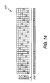
- FIG. 14 illustrates the first replacement jet group mask of FIG. 6, having its individual jet masks rotated in a round robin fashion to be utilized on a second jet group, adjacent to the first jet group.
- FIG. 15 illustrates the first replacement jet group mask of FIG. 6 assigned to a first jet group and the rotated version of the first replacement jet group mask as shown in FIG. 14, assigned to a second jet group, adjacent the first jet group, in accordance with one embodiment of the invention.
- various components of a typical inkjet printer 54 having a host computer 50 coupled thereto, is illustrated. These various components include control electronics of the inkjet printer 54 which are used to control ink droplet ejection from the ink jets of a printhead cartridge 44 of a printhead carriage 42 .
- a host computer 51 communicates with a processor 52 integral with the ink jet printer 54 .
- the host computer 51 runs driver software which issues print commands and sends data to the ink jet printer.
- the processor 52 communicates with a display and keypad 56 , memory 58 , and drive circuits 60 which control the print carriage motor 62 and paper motor 63 as well as powering a fan 66 .
- the processor 52 routes signals to print logic 70 , which actuates the ink jet nozzles of the ink jet printhead 44 .
- print logic 70 actuates the ink jet nozzles of the ink jet printhead 44 .
- the processor 52 in accordance with internal firmware stored in a portion of the memory 58 , selectively ejects ink droplets from the nozzles of the ink jet print head of each cartridge.
- the programming of the processor thus determines which nozzle of the print head is assigned to be used to eject an ink droplet onto any given grid location of the printed image when the relevant swath being printed calls for a droplet at that given grid location.
- the set of nozzle to grid location assignments is commonly referred to as a print mask, and the print mask definition is stored in memory 58 in the ink jet printer. The function and operation of a print mask is described in further detail below with reference to FIGS. 2-15.
- FIG. 2 one example of a print mask 100 having six print zones 102 a-f , and 17 individual jet masks 104 within each print zone 102 a-f (for a total of 102 individual jet masks 104 ), is illustrated.
- a separate print mask 100 is defined for each print-mode (number of passes) supported by the device and is used, unchanged, throughout the processing and printing of an image.
- the print mask 100 is made up of the individual jet masks 104 that determine the dots fired by each jet of a printhead.
- These individual jet masks 104 are configured such that adjacent jets on the printhead do not print horizontally or vertically adjacent dots during a single pass of the printhead across the recording medium. As described above, by avoiding horizontal and vertical adjacencies, printing anomalies and distortions caused by the coalescence of adjacent dots are substantially reduced.
- the individual jet masks 104 are arranged into zones 102 a-f that correspond to the number of passes for which that print mask was designed.
- a set of a jets having one jet from each zone makes up a complementary jet group. Jet masks for each jet in a jet group make up a jet group mask.
- jet mask no.'s 2 , 19 , 36 , 53 , 70 and 87 make up jet group mask no. 2 .
- FIG. 4 illustrates one embodiment of jet group mask no. 2 which includes the six jet masks 2 , 19 , 36 , 53 , 70 and 87 .
- These six jet masks 2 , 19 , 36 , 53 , 70 and 87 correspond to the six print zones 1 , 2 , 3 , 4 , 5 and 6 , respectively.
- each print zone 102 a-f prints a swath of the recording medium.
- a swath may be defined as the set of seventeen vertically adjacent raster lines on the recording medium within each respective print zone.
- the invention is not limited by any specific number of raster lines in a swath or jet masks in a given print zone. Different embodiments are envisioned which contain different numbers of raster lines per swath and/or jet masks per print zone.
- each jet mask 2 , 19 , 36 , 53 , 70 and 87 of the jet group mask of FIG. 3 is illustrated within its corresponding print zone 1 - 6 .
- Each raster line in a swath is printed by a single jet group with the work being shared between the members of that jet group. For example, during a first pass of the printhead over the recording medium, a swath of the recording medium is in print zone # 1 and the second jet of the printhead belonging to jet group 2 , prints dots on a corresponding second raster line 302 of the swath in accordance with jet mask 2 of FIG. 3 .
- jet mask 2 indicates which dots on the second raster line that jet 2 is responsible for printing. If the image requires ink to be printed on a dot for which the second jet is responsible for, this dot is printed during the first pass of the printhead over the swath when it is in print zone 1 .
- the recording media is advanced by an amount equal to the size of one zone such that the swath is now in print zone 2 .
- the second raster line 302 is aligned with a jet of the printhead which is a member of jet group 2 .
- the second raster line 302 which has been partially printed upon by the second jet when it was in print zone 1 , is now printed upon, as necessary, by the nineteenth jet of the printhead during a second pass of the printhead over the recording medium.
- the nineteenth jet and its corresponding jet mask 19 is the next member of jet group 2 which is responsible for printing the second raster line 302 in the swath. Jet mask 19 allocates which dots are printed by the nineteenth jet.
- the recording media is once again advanced by an amount equal to the size of one zone such that the swath is now in print zone 3 .
- the second raster line 302 is aligned with a 36th jet of the printhead and is printed upon, as necessary, by the 36th jet in accordance with jet mask 36 , during a third pass of the printhead over the recording medium.
- the above-described process is repeated until the swath has been printed upon in each print zone. As shown in FIG. 3, after the swath has completed the six-pass printing process and advanced through each of the six print zones, all the dots of the raster line 302 are accounted for.
- the term “dot” refers to any area of any shape or size on a recording medium, which may be covered by ink by a jet.
- FIG. 5 illustrates adjacent swaths of a recording medium which have undergone various stages of a six-pass (hence, six zone) printing process.
- the configuration of dots on the recording medium represents all the dots which may be printed in a given zone plus all previous zones.
- the image to be printed on the recording medium is a solid image, otherwise known as a “color fill,” covering the entire printable surface area.
- each dot is within a square box which represents the area on the recording medium which is intended to be covered by the dot of ink.
- these square boxes are illustrated merely for purposes of distinguishing the different areas or “dots” on the recording medium and are not visible on the actual recording medium.
- the dots printed on the recording medium may have overlapping areas such that there are no spaces between adjacent dots if a solid image, or full “color-fill” is desired.
- Open jet compensation is a modification to the multi-pass printing method described above, which allows for the use of information regarding defective or non-functional jets to dynamically modify the print masks of a printhead to compensate for the non-functional jets.
- This type of compensation scheme typically results in minimal degradation in print quality and no degradation in printing speed when there are relatively few defective jets in each jet group.
- a jet group contains defective jets
- the jet masks for the entire group are replaced with a replacement jet group mask that is appropriate for the number of functional jets remaining in that group.
- the maximum number of jets in a jet group is 6. Therefore, replacement jet group masks have been defined for 2, 3, 4 and 5 jets remaining. These replacement jet group masks take the responsibility of firing dots away from the defective jets and assigns the responsibility for printing the entire raster line to the remaining functional jets within that jet group.
- Defective jets can result from open traces, damaged drop ejection resistors, changed resistance values, or poor contact between the cartridge and the “flex circuit” which provides control signals to the cartridge. As discussed above, defective jets can also result from clogged jet nozzles. All of these errors will cause a jet or jets not to fire, resulting in anomalies in the printed image.
- the invention may utilize any well-known method or system of detecting defective jets in ink-jet printers. After one or more jets have been determined to be non-functional, a list of the defective jets may be generated, either automatically or via manual input by an operator of the ink jet printer, and stored within a memory of the ink-jet printer.
- This list of defective jets may then be accessed as necessary to update the print masks of the respective printhead cartridge.
- a novel method and system for detecting defective jets in a printhead is utilized. This novel method and system is described in a commonly-owned, concurrently filed patent application entitled, Method and System for Detecting Nonfunctional Elements in an Ink Jet Printer, U.S. application Ser. No.: 09/127,398, now U.S. Pat. No. 6,199,969 the entirety of which is incorporated by reference herein.
- a first replacement jet group mask 500 replaces the original jet group mask of that jet group in order to allocate printing of the entire raster line to the five remaining, functional jets of the jet group.
- the first replacement jet group mask 500 includes individual replacement jet masks 501 - 505 . When one of six jets in a jet group fails, that jet is shut off, or completely masked, and the original jet masks for the remaining five functional jets of that jet group are replaced by the replacement jet masks 501 - 505 .
- the first jet in the first print zone is simply turned off, or completely masked, such that it emits no ink, and replacement jet masks 501 - 505 are assigned to the remaining jets of that jet group.
- the replacement jet masks 501 - 505 are assigned to the remaining jets such that replacement jet masks 501 - 505 are assigned to the remaining functional jets for that jet group by order of ascending print zone numbers for each remaining functional jet. If the jet corresponding to print zone 1 has failed, then the first functional jet, by order of ascending print zones, is the jet in print zone 2 for that respective jet group. Therefore, replacement mask 501 is assigned to that jet in print zone 2 . Similarly, the replacement mask 502 is assigned to the jet in print zone 3 for that respective jet group, and replacement mask 503 is assigned to the jet in print zone 4 , and so on.
- the non-functional jet was determined to be in print zone 3 , for example, the first functional jet would be that corresponding to print zone 1 . Therefore, replacement mask 501 would be assigned to the respective jet for that jet group in print zone 1 , replacement mask 502 would be assigned to the respective jet in print zone 2 , and replacement mask 503 would be assigned to the respective jet in print zone 4 , and so on.
- the second replacement jet group mask 600 for a jet group having two non-functional jets is illustrated.
- the second set of replacement masks 600 includes replacement masks 601 - 604 each corresponding to one of the four remaining jets for that jet group. Similar to the allocation scheme described above with reference to FIG. 6, the replacement masks 601 - 604 are allocated to the remaining functional jets by order of ascending print zone numbers. For example, if a jet group has non-functional jets in print zones 1 and 4 , the first functional jet would be that in print zone 2 .
- replacement mask 601 would be assigned to that jet in print zone 2
- replacement mask 602 would be assigned to the corresponding jet in print zone 3
- replacement mask 603 would be assigned to the corresponding jet in print zone
- replacement mask 604 would be assigned to the corresponding jet in print zone 6 .
- the replacement masks 601 - 604 allow the four remaining functional jets of a jet group having two non-functional jets to print a complete raster line 605 , having no dots unaccounted for.
- FIG. 8 illustrates a third replacement jet group mask 700 for a jet group having three non-functional jets.
- the third set of replacement masks 700 includes replacement masks 701 - 703 , which are allocated to the three remaining functional jets of a jet group determined to have three non-functional jets.
- the replacement masks 701 - 703 are assigned to the remaining jets by order of ascending print zone numbers, as discussed above with reference to FIGS. 6 and 7.
- the replacement masks 701 - 703 allow the remaining jets of a jet group, having three non-functional jets, to print a complete raster line 704 , with no dots unaccounted for.
- FIG. 9 illustrates a fourth set of replacement masks 800 for a jet group having four non-functional jets.
- the fourth set of replacement masks 800 includes replacement masks 801 and 802 , which are allocated to the two remaining functional jets of a jet group determined to have four non-functional jets.
- the replacement masks 801 and 802 are assigned to the remaining jets by order of ascending print zone numbers, as discussed above with reference to FIGS. 6, 7 and 8 .
- the replacement masks 801 and 802 allow the remaining jets of a jet group, having four non-functional jets, to print a complete raster line 803 , with no dots unaccounted for.
- FIG. 10 illustrates the replacement masks 501 - 505 of the first replacement jet group mask 500 assigned to the remaining jets of a jet group having one non-functional jet, each remaining jet being in a respective print zone.
- the defective, or non-functional, jet is located in print zone 1 . Therefore, the jet in print zone 1 is completely masked, or turned off, such that no dots are fired onto a respective raster line of a recording medium in print zone 1 .
- the recording medium e.g., a sheet of paper
- the raster line advances to the next print zone and the next jet in the respective jet group may print dots on the raster line in accordance with the replacement jet mask 501 .
- the raster line successively passes through each of the print zones and the successive jets of the respective jet group print dots on the raster line in accordance with their respective replacement masks 501 - 505 .
- each dot, or designated printing area, on the raster line is accounted for, as shown by the completed raster line 506 .
- FIG. 11 shows a portion of a print mask having the first replacement jet group mask 500 of FIG. 6 assigned to jet group 12 because jet 12 of jet group 12 has been determined to be non-functional.
- jet 12 in print zone 1 , of jet group 12 , is completely masked and, therefore, not responsible for printing any dots on its respective raster line.
- the remaining jets 29 , 46 , 63 , 80 and 97 of jet group 12 have been assigned replacement masks 501 , 502 , 503 , 504 and 505 (FIG. 6 ), respectively, so as to compensate for the non-functional jet 12 .
- FIG. 12 illustrates adjacent swaths of a recording medium which have completed one or more stages of a six-zone printing process, with the first replacement jet group mask 500 of FIG. 6 assigned to jet group 12 .
- raster line 12 corresponding to the non-functional jet 12 , in print zone 1 , does not have any dots printed on it. However, as this raster line advances through each of the successive stages, it will be completely “filled in” with dots. As shown in FIG. 12, after raster line 12 has completed printing in print zone 6 , all of the dots of the raster line are filled in.
- the configuration of dots on the recording medium represents all the dots which may be printed in a given print zone plus all previous print zones.
- the image to be printed on the recording medium is a solid block of ink covering the entire printable surface area, otherwise referred to as a color fill.
- each dot is within a square box which represents the area on the recording medium W which is intended to be covered by the dot of ink.
- these square boxes are illustrated merely for the purpose of distinguishing the different areas on the recording medium and are not necessarily visible on the actual recording medium.
- the dots printed on the recording medium may have overlapping areas such that there are no spaces between adjacent dots if a solid image is desired.
- the same set of replacement masks corresponding to that number of non-functional jets, is used regardless of which jet in the jet group is identified as defective.
- FIG. 11 when replacement masks are applied to the overall default print mask for the entire printhead, some vertical adjacencies will occur. The occurrence of these vertical adjacencies is infrequent and results in minimal quality degradation.
- FIG. 13 illustrates the use of identical replacement jet masks for adjacent jet groups each having one defective jet.
- the first set of replacement jet masks 500 of FIG. 6 is used for each of the adjacent jet groups.
- adjacent remaining functional jets for both jet groups would produce a significant number of vertically adjacent dots within each print zone. This results in a significant increase in coalescence and, consequently, significant print quality degradation.
- a rotation scheme is used for the placement of the replacement masks. For example, if a jet fails in jet group 1 , then the replacement jet masks 501 - 505 (FIG. 6) are successively applied to the remaining functional jets of jet group 1 in the order 501 , 502 , 503 , 504 and 505 . Each replacement mask 501 - 505 is assigned to its respective jet by order of ascending print zone number, as described above.
- the replacement masks 501 - 505 are rotated such that they are applied to the remaining functional jets of jet group 2 in the order 502 , 503 , 504 , 505 and then 501 .
- This rotation process is repeated each time another jet in an another adjacent jet group, e.g., jet group 3 , is determined to be non-functional.
- the next rotation would result in the replacement masks being applied in the order 503 , 504 , 505 , 501 and then 502 .
- FIG. 14 illustrates the first set of replacement masks 500 after its replacement masks 501 - 505 have been rotated once such that the order that the replacement masks 501 - 505 are applied to the remaining functional jets of a jet group is now 502 , 503 , 504 , 505 and then back to 501 .
- replacement mask 502 is now the first one which is applied to the remaining functional jet in the lowest print zone
- replacement mask 503 is applied to the functional jet in the next lowest print zone and so on.
- Replacement mask 501 is now the last replacement mask to be applied.
- a first jet 130 of a first jet group is non-functional and a second jet 132 of a second, adjacent jet group is also non-functional.
- the replacement jet masks 501 - 505 are applied to the adjacent jet groups using the rotation scheme described above.
- replacement mask 501 is applied to a first remaining functional jet of the first jet group
- replacement mask 502 is applied to a second remaining functional jet, adjacent to the first remaining jet, of the second jet group.
- a firmware algorithm which updates one print zone of the print mask per pass of the printhead, allows for the smooth transition to open jet compensation.
- Print zone 1 always prints on an unprinted swath of the recording media.
- Print zone 2 always overprints the region printed by zone 1 and must use jet masks that correspond to the ones used by zone 1 in the previous pass of the printhead, etc. If a new defective jet is detected in the middle of printing job, only the jet masks corresponding to print zone 1 are updated for the next pass of the printhead. After completion of that pass, the jet masks corresponding to print zone 2 are updated but the jet masks corresponding to the remaining zones are left unchanged.
- the one or more failed jets may be compensated for by the remaining jets in a failed jet's respective jet group. This is accomplished by assigning replacement jet masks to the remaining functional jets within each jet group having one or more failed jets such that the remaining functional jets compensate for the failed jet(s) within their respective jet groups.
- This method and system does not utilize auxiliary jets which are idle during times of normal operation. Therefore, the resources of the printhead are maximized.
- the method and system of the invention allows the multi-pass printing method to reduce or eliminate coalescence of printed dots by following a compensation scheme which avoids the printing of vertically and horizontally adjacent dots during a single pass of the printhead over the recording medium. If adjacent jets are non-functional, then the order of assignment of the replacement masks to the remaining functional jets of the second jet group is rotated such that adjacent functional jets do not have identical replacement masks. In this way, vertical adjacencies are minimized.
- the method and system of the invention successively updates the portions of the print mask corresponding to only one print zone at a time. For example, if a defective jet is detected during printing, then prior to the next pass of the printhead over the recording medium, the jet masks corresponding to print zone 1 are updated and the printhead is then allowed to make another pass over the recording medium. Prior to the next pass, the jet masks corresponding to print zone 2 are updated, and so on. In this way, if a defective or nonfunctional jet is detected during the middle of a printing job, a smooth transition from the original jet group mask to the replacement jet group masked is achieved.
Abstract
Description
Claims (3)
Priority Applications (1)
| Application Number | Priority Date | Filing Date | Title |
|---|---|---|---|
| US09/929,196 US6398342B1 (en) | 1997-08-01 | 2001-08-13 | Open jet compensation during multi-pass printing |
Applications Claiming Priority (3)
| Application Number | Priority Date | Filing Date | Title |
|---|---|---|---|
| US5508097P | 1997-08-01 | 1997-08-01 | |
| US09/127,397 US6302511B1 (en) | 1997-08-01 | 1998-07-31 | Open jet compensation during multi-pass printing |
| US09/929,196 US6398342B1 (en) | 1997-08-01 | 2001-08-13 | Open jet compensation during multi-pass printing |
Related Parent Applications (1)
| Application Number | Title | Priority Date | Filing Date |
|---|---|---|---|
| US09/127,397 Continuation US6302511B1 (en) | 1997-08-01 | 1998-07-31 | Open jet compensation during multi-pass printing |
Publications (1)
| Publication Number | Publication Date |
|---|---|
| US6398342B1 true US6398342B1 (en) | 2002-06-04 |
Family
ID=21995457
Family Applications (3)
| Application Number | Title | Priority Date | Filing Date |
|---|---|---|---|
| US09/127,398 Expired - Lifetime US6199969B1 (en) | 1997-08-01 | 1998-07-31 | Method and system for detecting nonfunctional elements in an ink jet printer |
| US09/127,397 Expired - Lifetime US6302511B1 (en) | 1997-08-01 | 1998-07-31 | Open jet compensation during multi-pass printing |
| US09/929,196 Expired - Lifetime US6398342B1 (en) | 1997-08-01 | 2001-08-13 | Open jet compensation during multi-pass printing |
Family Applications Before (2)
| Application Number | Title | Priority Date | Filing Date |
|---|---|---|---|
| US09/127,398 Expired - Lifetime US6199969B1 (en) | 1997-08-01 | 1998-07-31 | Method and system for detecting nonfunctional elements in an ink jet printer |
| US09/127,397 Expired - Lifetime US6302511B1 (en) | 1997-08-01 | 1998-07-31 | Open jet compensation during multi-pass printing |
Country Status (6)
| Country | Link |
|---|---|
| US (3) | US6199969B1 (en) |
| EP (1) | EP0999935B1 (en) |
| AU (1) | AU8765098A (en) |
| CA (1) | CA2298530A1 (en) |
| DE (1) | DE69819510T2 (en) |
| WO (1) | WO1999008875A1 (en) |
Cited By (7)
| Publication number | Priority date | Publication date | Assignee | Title |
|---|---|---|---|---|
| US6659580B2 (en) | 1998-07-22 | 2003-12-09 | Canon Kabushiki Kaisha | Printing apparatus, control method therefor, and computer-readable memory |
| US20040017578A1 (en) * | 2002-07-25 | 2004-01-29 | Gallant John M. | Method of detecting bad dots in print zone |
| US6733100B1 (en) | 1999-08-24 | 2004-05-11 | Canon Kabushiki Kaisha | Printing apparatus, control method therefor, and computer-readable memory |
| US20050078133A1 (en) * | 2003-10-10 | 2005-04-14 | Pep-Lluis Molinet | Compensation of lateral position changes in printing |
| US20050110817A1 (en) * | 2003-11-24 | 2005-05-26 | Xerox Corporation | Ink jet processes |
| US20060061616A1 (en) * | 2004-09-17 | 2006-03-23 | Fuji Photo Film Co., Ltd. | Image recording apparatus and image correction method |
| US20060291745A1 (en) * | 2005-06-28 | 2006-12-28 | Samsung Electronics Co., Ltd. | Apparatus and method for compensating for defective pixel |
Families Citing this family (108)
| Publication number | Priority date | Publication date | Assignee | Title |
|---|---|---|---|---|
| US6786420B1 (en) | 1997-07-15 | 2004-09-07 | Silverbrook Research Pty. Ltd. | Data distribution mechanism in the form of ink dots on cards |
| US6702417B2 (en) * | 1997-07-12 | 2004-03-09 | Silverbrook Research Pty Ltd | Printing cartridge with capacitive sensor identification |
| US6618117B2 (en) | 1997-07-12 | 2003-09-09 | Silverbrook Research Pty Ltd | Image sensing apparatus including a microcontroller |
| AUPO850597A0 (en) | 1997-08-11 | 1997-09-04 | Silverbrook Research Pty Ltd | Image processing method and apparatus (art01a) |
| AUPO802797A0 (en) | 1997-07-15 | 1997-08-07 | Silverbrook Research Pty Ltd | Image processing method and apparatus (ART54) |
| US6879341B1 (en) | 1997-07-15 | 2005-04-12 | Silverbrook Research Pty Ltd | Digital camera system containing a VLIW vector processor |
| US6690419B1 (en) | 1997-07-15 | 2004-02-10 | Silverbrook Research Pty Ltd | Utilising eye detection methods for image processing in a digital image camera |
| US7207654B2 (en) | 1997-07-15 | 2007-04-24 | Silverbrook Research Pty Ltd | Ink jet with narrow chamber |
| US7110024B1 (en) | 1997-07-15 | 2006-09-19 | Silverbrook Research Pty Ltd | Digital camera system having motion deblurring means |
| US6985207B2 (en) | 1997-07-15 | 2006-01-10 | Silverbrook Research Pty Ltd | Photographic prints having magnetically recordable media |
| US7551201B2 (en) | 1997-07-15 | 2009-06-23 | Silverbrook Research Pty Ltd | Image capture and processing device for a print on demand digital camera system |
| US6624848B1 (en) | 1997-07-15 | 2003-09-23 | Silverbrook Research Pty Ltd | Cascading image modification using multiple digital cameras incorporating image processing |
| US20020008723A1 (en) * | 1998-07-21 | 2002-01-24 | Xin Wen | Printer and method of compensating for malperforming and inoperative ink nozzles in a print head |
| AUPP702098A0 (en) | 1998-11-09 | 1998-12-03 | Silverbrook Research Pty Ltd | Image creation method and apparatus (ART73) |
| US6270187B1 (en) | 1998-12-14 | 2001-08-07 | Hewlett-Packard Company | Method and apparatus for hiding errors in single-pass incremental printing |
| US6354689B1 (en) * | 1998-12-22 | 2002-03-12 | Eastman Kodak Company | Method of compensating for malperforming nozzles in a multitone inkjet printer |
| US6755495B2 (en) * | 2001-03-15 | 2004-06-29 | Hewlett-Packard Development Company, L.P. | Integrated control of power delivery to firing resistors for printhead assembly |
| US6729707B2 (en) * | 2002-04-30 | 2004-05-04 | Hewlett-Packard Development Company, L.P. | Self-calibration of power delivery control to firing resistors |
| AUPP996099A0 (en) | 1999-04-23 | 1999-05-20 | Silverbrook Research Pty Ltd | A method and apparatus(sprint01) |
| US6513434B1 (en) * | 1999-05-17 | 2003-02-04 | Fuji Photo Film Co., Ltd. | On-press recording type lithographic printing method and apparatus |
| AUPQ056099A0 (en) | 1999-05-25 | 1999-06-17 | Silverbrook Research Pty Ltd | A method and apparatus (pprint01) |
| US6637853B1 (en) | 1999-07-01 | 2003-10-28 | Lexmark International, Inc. | Faulty nozzle detection in an ink jet printer by printing test patterns and scanning with a fixed optical sensor |
| US6215557B1 (en) * | 1999-07-01 | 2001-04-10 | Lexmark International, Inc. | Entry of missing nozzle information in an ink jet printer |
| US6190000B1 (en) * | 1999-08-30 | 2001-02-20 | Hewlett-Packard Company | Method and apparatus for masking address out failures |
| GB2356601A (en) * | 1999-11-10 | 2001-05-30 | Lexmark Int Inc | Faulty nozzle mapping in an ink jet printer |
| US6443556B1 (en) * | 2000-02-29 | 2002-09-03 | Hewlett-Packard Company | Automated and semiautomated printmask generation for incremental printing |
| US6312098B1 (en) * | 2000-03-01 | 2001-11-06 | Hewlett-Packard Company | Banding reduction in incremental printing, through use of complementary weights for complementary printhead regions |
| JP2004501009A (en) * | 2000-06-30 | 2004-01-15 | シルバーブルック リサーチ ピーティワイ リミテッド | Anti-fault resistance of inkjet using adjacent nozzles |
| AU2005202028B2 (en) * | 2000-06-30 | 2006-08-17 | Memjet Technology Limited | Method for fault tolerance printing |
| SG155762A1 (en) * | 2000-06-30 | 2009-10-29 | Silverbrook Res Pty Ltd | Ink jet fault tolerance method |
| WO2002002331A1 (en) * | 2000-06-30 | 2002-01-10 | Silverbrook Research Pty Ltd | Ink jet fault tolerance using adjacent nozzles |
| US6378979B1 (en) * | 2000-11-30 | 2002-04-30 | Hewlett-Packard Company | Power short circuit detection and protection in a print system |
| US6554414B2 (en) | 2001-01-02 | 2003-04-29 | 3M Innovative Properties Company | Rotatable drum inkjet printing apparatus for radiation curable ink |
| US6550906B2 (en) | 2001-01-02 | 2003-04-22 | 3M Innovative Properties Company | Method and apparatus for inkjet printing using UV radiation curable ink |
| US6595615B2 (en) | 2001-01-02 | 2003-07-22 | 3M Innovative Properties Company | Method and apparatus for selection of inkjet printing parameters |
| US6464334B2 (en) * | 2001-01-08 | 2002-10-15 | Hewlett-Packard Company | Method for improving the quality of printing processes involving black pixel depletion |
| EP1250233A1 (en) * | 2001-01-09 | 2002-10-23 | Encad, Inc. | Ink jet printhead quality management system and method |
| US7046389B2 (en) * | 2001-04-04 | 2006-05-16 | Hewlett-Packard Development Company, L.P. | Variable density under/overprinting maps for improving print quality |
| DE60223322T2 (en) * | 2001-08-31 | 2008-03-13 | Canon K.K. | Image printing device and associated control method |
| US6543890B1 (en) | 2001-12-19 | 2003-04-08 | 3M Innovative Properties Company | Method and apparatus for radiation curing of ink used in inkjet printing |
| KR100406971B1 (en) * | 2002-01-31 | 2003-11-28 | 삼성전자주식회사 | Ink jet printer and printing system thereof and method of compensating for deteriorated nozzle |
| KR100437377B1 (en) * | 2002-02-15 | 2004-06-25 | 삼성전자주식회사 | An inkjet printer capable of checking as to whether nozzle is normal or not and method for informing about abnormal nozzle |
| DE60210208T2 (en) * | 2002-03-15 | 2006-12-28 | Agfa-Gevaert | Printing method and apparatus for replacing defective printing elements |
| US7036900B2 (en) | 2002-03-15 | 2006-05-02 | Agfa Gevaert | Printing method and apparatus for back-up of defective marking elements |
| US6874862B2 (en) * | 2002-04-26 | 2005-04-05 | Hewlett-Packard Development Company, L.P. | Inkjet printing device with multiple nozzles positioned to print at each target location on a print medium |
| TW539622B (en) * | 2002-05-16 | 2003-07-01 | Benq Corp | Method and related apparatus for performing short and open circuit detecting of ink-jet printer head |
| US6758547B2 (en) * | 2002-07-10 | 2004-07-06 | Lexmark International, Inc. | Method and apparatus for machine specific overcurrent detection |
| EP1405724B1 (en) * | 2002-10-03 | 2008-09-03 | Canon Kabushiki Kaisha | Ink-jet printing method, ink-jet printing apparatus, and program |
| US7227652B2 (en) * | 2002-10-17 | 2007-06-05 | Lexmark International, Inc. | Switching power supply, method of operation and device-and-power-supply assembly |
| US7404616B2 (en) | 2002-12-02 | 2008-07-29 | Silverbrook Research Pty Ltd | Printhead cartridge having an integrated circuit storing an identifier for use in mobile device |
| US7740347B2 (en) | 2002-12-02 | 2010-06-22 | Silverbrook Research Pty Ltd | Ink usage tracking in a cartridge for a mobile device |
| US7519772B2 (en) | 2003-12-02 | 2009-04-14 | Silverbrook Research Pty Ltd | Method of updating IC cache |
| US7121639B2 (en) | 2002-12-02 | 2006-10-17 | Silverbrook Research Pty Ltd | Data rate equalisation to account for relatively different printhead widths |
| AU2003302611B2 (en) * | 2002-12-02 | 2007-04-19 | Memjet Technology Limited | Dead nozzle compensation |
| CN100415523C (en) * | 2002-12-31 | 2008-09-03 | 杭州宏华数码科技股份有限公司 | Spray head installing method of ink-jet printing machine |
| US7546226B1 (en) | 2003-03-12 | 2009-06-09 | Microsoft Corporation | Architecture for automating analytical view of business applications |
| US7313561B2 (en) | 2003-03-12 | 2007-12-25 | Microsoft Corporation | Model definition schema |
| US20040241667A1 (en) * | 2003-05-30 | 2004-12-02 | Chesk William G. | Pulse-jet ejection head diagnostic system |
| US20050018006A1 (en) * | 2003-06-27 | 2005-01-27 | Samsung Electronics Co., Ltd. | Method of determining missing nozzles in an inkjet printer |
| US7011395B2 (en) * | 2003-06-27 | 2006-03-14 | Lexmark International, Inc. | Print head energy storage |
| US6825675B1 (en) | 2003-06-27 | 2004-11-30 | Lexmark International, Inc. | Method for detecting a shorted printhead in a printer having at least two printheads |
| US7140711B2 (en) | 2003-07-21 | 2006-11-28 | 3M Innovative Properties Company | Method and apparatus for inkjet printing using radiation curable ink |
| US7101016B2 (en) * | 2004-01-18 | 2006-09-05 | Hewlett-Packard Company | Adjustment of fluid-ejection energy to yield fluid drop masses having consistent ratio |
| US7237864B2 (en) * | 2004-02-06 | 2007-07-03 | Hewlett-Packard Development Company, L.P. | Fluid ejection device identification |
| US7449662B2 (en) * | 2004-04-26 | 2008-11-11 | Hewlett-Packard Development Company, L.P. | Air heating apparatus |
| US7227756B2 (en) * | 2004-05-27 | 2007-06-05 | Lexmark International, Inc. | Power supply keying arrangement for use with an electrical apparatus |
| US7461925B2 (en) * | 2005-03-04 | 2008-12-09 | Hewlett-Packard Development Company, L.P. | Adjusting power |
| US7756681B2 (en) * | 2005-03-10 | 2010-07-13 | Hewlett-Packard Development Company, L.P. | Power supply circuit |
| US7506180B2 (en) * | 2005-03-10 | 2009-03-17 | Hewlett-Packard Development Company, L.P. | System and method for determining the power drawn from a switching power supply by counting the number of times a switching power supply switch is enabled |
| US7665819B2 (en) * | 2005-04-21 | 2010-02-23 | Tonerhead, Inc. | Method and apparatus for a printer cartridge tester |
| US7673958B2 (en) * | 2005-06-21 | 2010-03-09 | Hewlett-Packard Development Company, L.P. | Defective imaging element compensation |
| US7635174B2 (en) * | 2005-08-22 | 2009-12-22 | Lexmark International, Inc. | Heater chip test circuit and methods for using the same |
| KR100750131B1 (en) * | 2005-09-23 | 2007-08-21 | 삼성전자주식회사 | Apparatus and method for testing nozzle |
| US7467853B2 (en) * | 2005-12-05 | 2008-12-23 | Silverbrook Research Pty Ltd | Cradle for printhead cartridge having power regulation interface |
| US7461910B2 (en) * | 2005-12-05 | 2008-12-09 | Silverbrook Research Pty Ltd | Printing system having power storage printhead cartridge interface |
| US7722185B2 (en) | 2005-12-05 | 2010-05-25 | Silverbrook Research Pty Ltd | Cradle for printhead cartridge having power storage interface |
| US7465020B2 (en) * | 2005-12-05 | 2008-12-16 | Silverbrook Research Pty Ltd | Printhead cartridge interface having power storage |
| US7461922B2 (en) * | 2005-12-05 | 2008-12-09 | Silverbrook Research Pty Ltd | Printing system having power regulating printhead cartridge interface |
| US7448718B2 (en) * | 2006-09-29 | 2008-11-11 | Eastman Kodak Company | Determining defective resistors in inkjet printers |
| EP2073983A4 (en) * | 2006-10-09 | 2012-08-01 | Silverbrook Res Pty Ltd | Printhead ic with open actuator test |
| US7384128B2 (en) | 2006-10-10 | 2008-06-10 | Silverbrook Research Pty Ltd | Printhead IC with nozzle array for linking with adjacent printhead IC's |
| US7938500B2 (en) | 2006-10-10 | 2011-05-10 | Silverbrook Research Pty Ltd | Printhead IC with multiple temperature sensors |
| US7413288B2 (en) | 2006-10-10 | 2008-08-19 | Silverbrook Research Pty Ltd | Externally applied write addresses for printhead integrated circuits |
| US7819494B2 (en) | 2006-10-10 | 2010-10-26 | Silverbrook Research Pty Ltd | Printhead IC with multi-stage print data loading and firing |
| US7722163B2 (en) | 2006-10-10 | 2010-05-25 | Silverbrook Research Pty Ltd | Printhead IC with clock recovery circuit |
| US7780256B2 (en) | 2006-10-10 | 2010-08-24 | Silverbrook Research Pty Ltd | Printhead IC with spaced nozzle firing sequence |
| US7681970B2 (en) | 2006-10-10 | 2010-03-23 | Silverbrook Research Pty Ltd | Self initialising printhead IC |
| US7604321B2 (en) | 2006-10-10 | 2009-10-20 | Silverbrook Research Pty Ltd | Thermal inkjet printhead with de-clog firing mode |
| US7425048B2 (en) | 2006-10-10 | 2008-09-16 | Silverbrook Research Pty Ltd | Printhead IC with de-activatable temperature sensor |
| US7845747B2 (en) | 2006-10-10 | 2010-12-07 | Silverbrook Research Pty Ltd | Printhead with sub-ejection pulse for non-firing nozzles |
| US8016389B2 (en) | 2006-10-10 | 2011-09-13 | Silverbrook Research Pty Ltd | Printhead IC with staggered nozzle firing pulses |
| US7946674B2 (en) | 2006-10-10 | 2011-05-24 | Silverbrook Research Pty Ltd | Printhead IC with open actuator test |
| US7425047B2 (en) | 2006-10-10 | 2008-09-16 | Silverbrook Research Pty Ltd | Printhead IC compatible with mutally incompatible print engine controllers |
| US7793117B2 (en) * | 2006-10-12 | 2010-09-07 | Hewlett-Packard Development Company, L.P. | Method, apparatus and system for determining power supply to a load |
| US8564252B2 (en) | 2006-11-10 | 2013-10-22 | Cypress Semiconductor Corporation | Boost buffer aid for reference buffer |
| US8157340B2 (en) * | 2006-11-21 | 2012-04-17 | Intermec Ip Corp. | Apparatus and method for thermal printers that employ a battery or other portable power source |
| US7753466B2 (en) * | 2006-12-21 | 2010-07-13 | Hon Hai Precision Industry Co., Ltd. | Device for manufacturing color printing and method using same |
| US8035401B2 (en) | 2007-04-18 | 2011-10-11 | Cypress Semiconductor Corporation | Self-calibrating driver for charging a capacitive load to a desired voltage |
| US7815275B2 (en) * | 2007-07-27 | 2010-10-19 | Shilin Guo | Interactive visual card-selection process for mitigating light-area banding in a pagewide array |
| US7748815B2 (en) * | 2007-08-06 | 2010-07-06 | Hewlett-Packard Development Company, L.P. | Disabling a nozzle |
| US8194376B2 (en) * | 2009-03-09 | 2012-06-05 | Hewlett-Packard Development Company, L.P. | Energy storage discharge circuitry |
| US8364870B2 (en) | 2010-09-30 | 2013-01-29 | Cypress Semiconductor Corporation | USB port connected to multiple USB compliant devices |
| US9667240B2 (en) | 2011-12-02 | 2017-05-30 | Cypress Semiconductor Corporation | Systems and methods for starting up analog circuits |
| US8733885B1 (en) * | 2013-02-13 | 2014-05-27 | Hewlett-Packard Development Company, L.P. | Print head array testing |
| WO2018071024A1 (en) * | 2016-10-13 | 2018-04-19 | Hewlett-Packard Development Company, L.P. | Switches for bypass capacitors |
| WO2018143989A1 (en) * | 2017-02-02 | 2018-08-09 | Hewlett-Packard Development Company, L.P. | Nozzle replacement to minimize visual discontinuities |
| US11090924B2 (en) * | 2017-04-14 | 2021-08-17 | Hewlett-Packard Development Company, L.P. | Fluidic die with nozzle displacement mask register |
| WO2019212511A1 (en) | 2018-04-30 | 2019-11-07 | Hewlett-Packard Development Company, L.P. | Potential printhead strike determination |
Citations (16)
| Publication number | Priority date | Publication date | Assignee | Title |
|---|---|---|---|---|
| JPS6367164A (en) | 1986-09-10 | 1988-03-25 | Mitsubishi Electric Corp | Printing method by serial thermal printer |
| US4748453A (en) | 1987-07-21 | 1988-05-31 | Xerox Corporation | Spot deposition for liquid ink printing |
| US4963882A (en) * | 1988-12-27 | 1990-10-16 | Hewlett-Packard Company | Printing of pixel locations by an ink jet printer using multiple nozzles for each pixel or pixel row |
| US4965593A (en) | 1989-07-27 | 1990-10-23 | Hewlett-Packard Company | Print quality of dot printers |
| US4967203A (en) | 1989-09-29 | 1990-10-30 | Hewlett-Packard Company | Interlace printing process |
| EP0394699A1 (en) | 1989-04-24 | 1990-10-31 | Lexmark International, Inc. | Apparatus and method for detecting failure of thermal heaters in ink jet printers |
| US4999646A (en) | 1989-11-29 | 1991-03-12 | Hewlett-Packard Company | Method for enhancing the uniformity and consistency of dot formation produced by color ink jet printing |
| JPH03259755A (en) | 1990-03-09 | 1991-11-19 | Hitachi Ltd | Specifying device for accident aspect of electric power system |
| US5124720A (en) | 1990-08-01 | 1992-06-23 | Hewlett-Packard Company | Fault-tolerant dot-matrix printing |
| JPH0728525A (en) | 1993-07-15 | 1995-01-31 | Toshiba Corp | Self-advancing robot |
| EP0694396A2 (en) | 1994-07-21 | 1996-01-31 | Canon Kabushiki Kaisha | Recording apparatus for performing complementary recording and recording method therefor |
| WO1996032263A1 (en) | 1995-04-12 | 1996-10-17 | Eastman Kodak Company | Nozzle duplication for fault tolerance in integrated printing heads |
| EP0855270A2 (en) | 1997-01-24 | 1998-07-29 | Hewlett-Packard Company | System and method for printing with a portion of an ink-jet print head |
| EP0863004A2 (en) | 1997-03-04 | 1998-09-09 | Hewlett-Packard Company | Dynamic multi-pass print mode corrections to compensate for malfunctioning inkjet nozzles |
| WO1998040222A1 (en) | 1997-03-12 | 1998-09-17 | Raster Graphics Inc. | Printing system and ink jet nozzle control method and apparatus having compensation for malfunctioning nozzles |
| US6168261B1 (en) * | 1992-04-27 | 2001-01-02 | Canon Kabushiki Kaisha | Recording apparatus and recording method |
Family Cites Families (6)
| Publication number | Priority date | Publication date | Assignee | Title |
|---|---|---|---|---|
| US4595935A (en) * | 1984-08-14 | 1986-06-17 | Ncr Canada Ltd. | System for detecting defective thermal printhead elements |
| JPH03256755A (en) | 1990-03-08 | 1991-11-15 | Toshiba Corp | Thermal recorder |
| JPH07285225A (en) | 1994-04-15 | 1995-10-31 | Nec Corp | Print compensation for ink jet printer and device therefor |
| JP3590702B2 (en) * | 1995-11-16 | 2004-11-17 | 富士写真フイルム株式会社 | Method and apparatus for measuring resistance data of thermal head and thermal printer having the same |
| US5789934A (en) * | 1996-05-23 | 1998-08-04 | Hewlett-Packard Company | Test circuit including a power supply with a current transformer to monitor capacitor output current |
| US6089693A (en) * | 1998-01-08 | 2000-07-18 | Xerox Corporation | Pagewidth ink jet printer including multiple pass defective nozzle correction |
-
1998
- 1998-07-31 WO PCT/US1998/016101 patent/WO1999008875A1/en active IP Right Grant
- 1998-07-31 EP EP98939165A patent/EP0999935B1/en not_active Expired - Lifetime
- 1998-07-31 DE DE69819510T patent/DE69819510T2/en not_active Expired - Lifetime
- 1998-07-31 US US09/127,398 patent/US6199969B1/en not_active Expired - Lifetime
- 1998-07-31 CA CA002298530A patent/CA2298530A1/en not_active Abandoned
- 1998-07-31 AU AU87650/98A patent/AU8765098A/en not_active Abandoned
- 1998-07-31 US US09/127,397 patent/US6302511B1/en not_active Expired - Lifetime
-
2001
- 2001-08-13 US US09/929,196 patent/US6398342B1/en not_active Expired - Lifetime
Patent Citations (17)
| Publication number | Priority date | Publication date | Assignee | Title |
|---|---|---|---|---|
| JPS6367164A (en) | 1986-09-10 | 1988-03-25 | Mitsubishi Electric Corp | Printing method by serial thermal printer |
| US4748453A (en) | 1987-07-21 | 1988-05-31 | Xerox Corporation | Spot deposition for liquid ink printing |
| US4963882B1 (en) * | 1988-12-27 | 1996-10-29 | Hewlett Packard Co | Printing of pixel locations by an ink jet printer using multiple nozzles for each pixel or pixel row |
| US4963882A (en) * | 1988-12-27 | 1990-10-16 | Hewlett-Packard Company | Printing of pixel locations by an ink jet printer using multiple nozzles for each pixel or pixel row |
| EP0394699A1 (en) | 1989-04-24 | 1990-10-31 | Lexmark International, Inc. | Apparatus and method for detecting failure of thermal heaters in ink jet printers |
| US4965593A (en) | 1989-07-27 | 1990-10-23 | Hewlett-Packard Company | Print quality of dot printers |
| US4967203A (en) | 1989-09-29 | 1990-10-30 | Hewlett-Packard Company | Interlace printing process |
| US4999646A (en) | 1989-11-29 | 1991-03-12 | Hewlett-Packard Company | Method for enhancing the uniformity and consistency of dot formation produced by color ink jet printing |
| JPH03259755A (en) | 1990-03-09 | 1991-11-19 | Hitachi Ltd | Specifying device for accident aspect of electric power system |
| US5124720A (en) | 1990-08-01 | 1992-06-23 | Hewlett-Packard Company | Fault-tolerant dot-matrix printing |
| US6168261B1 (en) * | 1992-04-27 | 2001-01-02 | Canon Kabushiki Kaisha | Recording apparatus and recording method |
| JPH0728525A (en) | 1993-07-15 | 1995-01-31 | Toshiba Corp | Self-advancing robot |
| EP0694396A2 (en) | 1994-07-21 | 1996-01-31 | Canon Kabushiki Kaisha | Recording apparatus for performing complementary recording and recording method therefor |
| WO1996032263A1 (en) | 1995-04-12 | 1996-10-17 | Eastman Kodak Company | Nozzle duplication for fault tolerance in integrated printing heads |
| EP0855270A2 (en) | 1997-01-24 | 1998-07-29 | Hewlett-Packard Company | System and method for printing with a portion of an ink-jet print head |
| EP0863004A2 (en) | 1997-03-04 | 1998-09-09 | Hewlett-Packard Company | Dynamic multi-pass print mode corrections to compensate for malfunctioning inkjet nozzles |
| WO1998040222A1 (en) | 1997-03-12 | 1998-09-17 | Raster Graphics Inc. | Printing system and ink jet nozzle control method and apparatus having compensation for malfunctioning nozzles |
Cited By (10)
| Publication number | Priority date | Publication date | Assignee | Title |
|---|---|---|---|---|
| US6659580B2 (en) | 1998-07-22 | 2003-12-09 | Canon Kabushiki Kaisha | Printing apparatus, control method therefor, and computer-readable memory |
| US6733100B1 (en) | 1999-08-24 | 2004-05-11 | Canon Kabushiki Kaisha | Printing apparatus, control method therefor, and computer-readable memory |
| US20040017578A1 (en) * | 2002-07-25 | 2004-01-29 | Gallant John M. | Method of detecting bad dots in print zone |
| US20050078133A1 (en) * | 2003-10-10 | 2005-04-14 | Pep-Lluis Molinet | Compensation of lateral position changes in printing |
| US6942308B2 (en) * | 2003-10-10 | 2005-09-13 | Hewlett-Packard Development Company, L.P. | Compensation of lateral position changes in printing |
| US20050110817A1 (en) * | 2003-11-24 | 2005-05-26 | Xerox Corporation | Ink jet processes |
| US7021739B2 (en) | 2003-11-24 | 2006-04-04 | Xerox Corporation | Ink jet processes |
| US20060061616A1 (en) * | 2004-09-17 | 2006-03-23 | Fuji Photo Film Co., Ltd. | Image recording apparatus and image correction method |
| US7289248B2 (en) * | 2004-09-17 | 2007-10-30 | Fujifilm Corporation | Image recording apparatus and image correction method |
| US20060291745A1 (en) * | 2005-06-28 | 2006-12-28 | Samsung Electronics Co., Ltd. | Apparatus and method for compensating for defective pixel |
Also Published As
| Publication number | Publication date |
|---|---|
| WO1999008875A1 (en) | 1999-02-25 |
| CA2298530A1 (en) | 1999-02-25 |
| US6199969B1 (en) | 2001-03-13 |
| EP0999935A1 (en) | 2000-05-17 |
| AU8765098A (en) | 1999-03-08 |
| DE69819510D1 (en) | 2003-12-11 |
| US6302511B1 (en) | 2001-10-16 |
| EP0999935B1 (en) | 2003-11-05 |
| DE69819510T2 (en) | 2004-09-23 |
Similar Documents
| Publication | Publication Date | Title |
|---|---|---|
| US6398342B1 (en) | Open jet compensation during multi-pass printing | |
| US5640183A (en) | Redundant nozzle dot matrix printheads and method of use | |
| US6695435B1 (en) | Selective replacement for artifact reduction | |
| US6310640B1 (en) | Banding reduction in multipass printmodes | |
| JP3472250B2 (en) | Ink jet printing method and apparatus | |
| US9028028B2 (en) | Defective printer nozzle compensation control | |
| JP4250264B2 (en) | Recording apparatus, control method therefor, and computer-readable memory | |
| JPH106488A (en) | Ink jet recording method and its apparatus | |
| JP2000071432A (en) | Method and device for compensating troubled ink jet nozzle | |
| US20090128594A1 (en) | Defective nozzle replacement in a printer | |
| AU2000253742B2 (en) | Ink jet fault tolerance using adjacent nozzles | |
| US6776474B2 (en) | Method of printing color images with ink jet printer | |
| US6273549B1 (en) | Multiple pass color shift correction technique for an inkjet printer | |
| JP2003276186A (en) | Print method and printer with error correction | |
| US6536869B1 (en) | Hybrid printmask for multidrop inkjet printer | |
| EP1303409B1 (en) | Ink jet fault tolerance using extra ink dots | |
| JP2004174816A (en) | Ink jet recorder | |
| JPH07256874A (en) | Equipment and method for recording | |
| EP0730367A1 (en) | Method and system for interlaced printing | |
| JPH11115223A (en) | Printing apparatus | |
| JP7268370B2 (en) | Recording device and recording method | |
| EP2616245B1 (en) | Method of camouflaging artefacts in high coverage areas in images to be printed | |
| JP2002361988A (en) | Serial printer and its operating method for printing test pattern | |
| JP2004174750A (en) | Ink jet recorder | |
| JPH08267834A (en) | Multi-pass printing method |
Legal Events
| Date | Code | Title | Description |
|---|---|---|---|
| FEPP | Fee payment procedure |
Free format text: PAYOR NUMBER ASSIGNED (ORIGINAL EVENT CODE: ASPN); ENTITY STATUS OF PATENT OWNER: LARGE ENTITY |
|
| STCF | Information on status: patent grant |
Free format text: PATENTED CASE |
|
| FPAY | Fee payment |
Year of fee payment: 4 |
|
| AS | Assignment |
Owner name: EASTMAN KODAK COMPANY, NEW YORK Free format text: MERGER;ASSIGNOR:ENCAD, INC.;REEL/FRAME:019754/0597 Effective date: 20060313 |
|
| FPAY | Fee payment |
Year of fee payment: 8 |
|
| AS | Assignment |
Owner name: CITICORP NORTH AMERICA, INC., AS AGENT, NEW YORK Free format text: SECURITY INTEREST;ASSIGNORS:EASTMAN KODAK COMPANY;PAKON, INC.;REEL/FRAME:028201/0420 Effective date: 20120215 |
|
| AS | Assignment |
Owner name: WILMINGTON TRUST, NATIONAL ASSOCIATION, AS AGENT, Free format text: PATENT SECURITY AGREEMENT;ASSIGNORS:EASTMAN KODAK COMPANY;PAKON, INC.;REEL/FRAME:030122/0235 Effective date: 20130322 Owner name: WILMINGTON TRUST, NATIONAL ASSOCIATION, AS AGENT, MINNESOTA Free format text: PATENT SECURITY AGREEMENT;ASSIGNORS:EASTMAN KODAK COMPANY;PAKON, INC.;REEL/FRAME:030122/0235 Effective date: 20130322 |
|
| AS | Assignment |
Owner name: BARCLAYS BANK PLC, AS ADMINISTRATIVE AGENT, NEW YORK Free format text: INTELLECTUAL PROPERTY SECURITY AGREEMENT (SECOND LIEN);ASSIGNORS:EASTMAN KODAK COMPANY;FAR EAST DEVELOPMENT LTD.;FPC INC.;AND OTHERS;REEL/FRAME:031159/0001 Effective date: 20130903 Owner name: JPMORGAN CHASE BANK, N.A., AS ADMINISTRATIVE, DELAWARE Free format text: INTELLECTUAL PROPERTY SECURITY AGREEMENT (FIRST LIEN);ASSIGNORS:EASTMAN KODAK COMPANY;FAR EAST DEVELOPMENT LTD.;FPC INC.;AND OTHERS;REEL/FRAME:031158/0001 Effective date: 20130903 Owner name: BARCLAYS BANK PLC, AS ADMINISTRATIVE AGENT, NEW YO Free format text: INTELLECTUAL PROPERTY SECURITY AGREEMENT (SECOND LIEN);ASSIGNORS:EASTMAN KODAK COMPANY;FAR EAST DEVELOPMENT LTD.;FPC INC.;AND OTHERS;REEL/FRAME:031159/0001 Effective date: 20130903 Owner name: EASTMAN KODAK COMPANY, NEW YORK Free format text: RELEASE OF SECURITY INTEREST IN PATENTS;ASSIGNORS:CITICORP NORTH AMERICA, INC., AS SENIOR DIP AGENT;WILMINGTON TRUST, NATIONAL ASSOCIATION, AS JUNIOR DIP AGENT;REEL/FRAME:031157/0451 Effective date: 20130903 Owner name: PAKON, INC., NEW YORK Free format text: RELEASE OF SECURITY INTEREST IN PATENTS;ASSIGNORS:CITICORP NORTH AMERICA, INC., AS SENIOR DIP AGENT;WILMINGTON TRUST, NATIONAL ASSOCIATION, AS JUNIOR DIP AGENT;REEL/FRAME:031157/0451 Effective date: 20130903 Owner name: JPMORGAN CHASE BANK, N.A., AS ADMINISTRATIVE, DELA Free format text: INTELLECTUAL PROPERTY SECURITY AGREEMENT (FIRST LIEN);ASSIGNORS:EASTMAN KODAK COMPANY;FAR EAST DEVELOPMENT LTD.;FPC INC.;AND OTHERS;REEL/FRAME:031158/0001 Effective date: 20130903 Owner name: BANK OF AMERICA N.A., AS AGENT, MASSACHUSETTS Free format text: INTELLECTUAL PROPERTY SECURITY AGREEMENT (ABL);ASSIGNORS:EASTMAN KODAK COMPANY;FAR EAST DEVELOPMENT LTD.;FPC INC.;AND OTHERS;REEL/FRAME:031162/0117 Effective date: 20130903 |
|
| FPAY | Fee payment |
Year of fee payment: 12 |
|
| AS | Assignment |
Owner name: EASTMAN KODAK COMPANY, NEW YORK Free format text: RELEASE BY SECURED PARTY;ASSIGNOR:JP MORGAN CHASE BANK N.A.;REEL/FRAME:041581/0943 Effective date: 20170126 Owner name: EASTMAN KODAK COMPANY, NEW YORK Free format text: RELEASE BY SECURED PARTY;ASSIGNOR:BANK OF AMERICA, N.A.;REEL/FRAME:041582/0013 Effective date: 20170126 |
|
| AS | Assignment |
Owner name: COMMERCIAL COPY INNOVATIONS, INC., CALIFORNIA Free format text: ASSIGNMENT OF ASSIGNORS INTEREST;ASSIGNOR:EASTMAN KODAK COMPANY;REEL/FRAME:041735/0922 Effective date: 20161209 |
|
| AS | Assignment |
Owner name: KODAK (NEAR EAST), INC., NEW YORK Free format text: RELEASE BY SECURED PARTY;ASSIGNOR:JP MORGAN CHASE BANK, N.A., AS ADMINISTRATIVE AGENT;REEL/FRAME:049814/0001 Effective date: 20190617 Owner name: NPEC, INC., NEW YORK Free format text: RELEASE BY SECURED PARTY;ASSIGNOR:JP MORGAN CHASE BANK, N.A., AS ADMINISTRATIVE AGENT;REEL/FRAME:049814/0001 Effective date: 20190617 Owner name: QUALEX, INC., NEW YORK Free format text: RELEASE BY SECURED PARTY;ASSIGNOR:JP MORGAN CHASE BANK, N.A., AS ADMINISTRATIVE AGENT;REEL/FRAME:049814/0001 Effective date: 20190617 Owner name: CREO MANUFACTURING AMERICA LLC, NEW YORK Free format text: RELEASE BY SECURED PARTY;ASSIGNOR:JP MORGAN CHASE BANK, N.A., AS ADMINISTRATIVE AGENT;REEL/FRAME:049814/0001 Effective date: 20190617 Owner name: EASTMAN KODAK COMPANY, NEW YORK Free format text: RELEASE BY SECURED PARTY;ASSIGNOR:JP MORGAN CHASE BANK, N.A., AS ADMINISTRATIVE AGENT;REEL/FRAME:049814/0001 Effective date: 20190617 Owner name: LASER PACIFIC MEDIA CORPORATION, NEW YORK Free format text: RELEASE BY SECURED PARTY;ASSIGNOR:JP MORGAN CHASE BANK, N.A., AS ADMINISTRATIVE AGENT;REEL/FRAME:049814/0001 Effective date: 20190617 Owner name: KODAK AVIATION LEASING LLC, NEW YORK Free format text: RELEASE BY SECURED PARTY;ASSIGNOR:JP MORGAN CHASE BANK, N.A., AS ADMINISTRATIVE AGENT;REEL/FRAME:049814/0001 Effective date: 20190617 Owner name: FPC, INC., NEW YORK Free format text: RELEASE BY SECURED PARTY;ASSIGNOR:JP MORGAN CHASE BANK, N.A., AS ADMINISTRATIVE AGENT;REEL/FRAME:049814/0001 Effective date: 20190617 Owner name: KODAK PORTUGUESA LIMITED, NEW YORK Free format text: RELEASE BY SECURED PARTY;ASSIGNOR:JP MORGAN CHASE BANK, N.A., AS ADMINISTRATIVE AGENT;REEL/FRAME:049814/0001 Effective date: 20190617 Owner name: KODAK AMERICAS, LTD., NEW YORK Free format text: RELEASE BY SECURED PARTY;ASSIGNOR:JP MORGAN CHASE BANK, N.A., AS ADMINISTRATIVE AGENT;REEL/FRAME:049814/0001 Effective date: 20190617 Owner name: KODAK REALTY, INC., NEW YORK Free format text: RELEASE BY SECURED PARTY;ASSIGNOR:JP MORGAN CHASE BANK, N.A., AS ADMINISTRATIVE AGENT;REEL/FRAME:049814/0001 Effective date: 20190617 Owner name: KODAK PHILIPPINES, LTD., NEW YORK Free format text: RELEASE BY SECURED PARTY;ASSIGNOR:JP MORGAN CHASE BANK, N.A., AS ADMINISTRATIVE AGENT;REEL/FRAME:049814/0001 Effective date: 20190617 Owner name: FAR EAST DEVELOPMENT LTD., NEW YORK Free format text: RELEASE BY SECURED PARTY;ASSIGNOR:JP MORGAN CHASE BANK, N.A., AS ADMINISTRATIVE AGENT;REEL/FRAME:049814/0001 Effective date: 20190617 Owner name: KODAK IMAGING NETWORK, INC., NEW YORK Free format text: RELEASE BY SECURED PARTY;ASSIGNOR:JP MORGAN CHASE BANK, N.A., AS ADMINISTRATIVE AGENT;REEL/FRAME:049814/0001 Effective date: 20190617 Owner name: PAKON, INC., NEW YORK Free format text: RELEASE BY SECURED PARTY;ASSIGNOR:JP MORGAN CHASE BANK, N.A., AS ADMINISTRATIVE AGENT;REEL/FRAME:049814/0001 Effective date: 20190617 |
|
| AS | Assignment |
Owner name: FAR EAST DEVELOPMENT LTD., NEW YORK Free format text: RELEASE BY SECURED PARTY;ASSIGNOR:BARCLAYS BANK PLC;REEL/FRAME:052773/0001 Effective date: 20170202 Owner name: KODAK AMERICAS LTD., NEW YORK Free format text: RELEASE BY SECURED PARTY;ASSIGNOR:BARCLAYS BANK PLC;REEL/FRAME:052773/0001 Effective date: 20170202 Owner name: EASTMAN KODAK COMPANY, NEW YORK Free format text: RELEASE BY SECURED PARTY;ASSIGNOR:BARCLAYS BANK PLC;REEL/FRAME:052773/0001 Effective date: 20170202 Owner name: NPEC INC., NEW YORK Free format text: RELEASE BY SECURED PARTY;ASSIGNOR:BARCLAYS BANK PLC;REEL/FRAME:052773/0001 Effective date: 20170202 Owner name: QUALEX INC., NEW YORK Free format text: RELEASE BY SECURED PARTY;ASSIGNOR:BARCLAYS BANK PLC;REEL/FRAME:052773/0001 Effective date: 20170202 Owner name: LASER PACIFIC MEDIA CORPORATION, NEW YORK Free format text: RELEASE BY SECURED PARTY;ASSIGNOR:BARCLAYS BANK PLC;REEL/FRAME:052773/0001 Effective date: 20170202 Owner name: KODAK (NEAR EAST) INC., NEW YORK Free format text: RELEASE BY SECURED PARTY;ASSIGNOR:BARCLAYS BANK PLC;REEL/FRAME:052773/0001 Effective date: 20170202 Owner name: FPC INC., NEW YORK Free format text: RELEASE BY SECURED PARTY;ASSIGNOR:BARCLAYS BANK PLC;REEL/FRAME:052773/0001 Effective date: 20170202 Owner name: KODAK REALTY INC., NEW YORK Free format text: RELEASE BY SECURED PARTY;ASSIGNOR:BARCLAYS BANK PLC;REEL/FRAME:052773/0001 Effective date: 20170202 Owner name: KODAK PHILIPPINES LTD., NEW YORK Free format text: RELEASE BY SECURED PARTY;ASSIGNOR:BARCLAYS BANK PLC;REEL/FRAME:052773/0001 Effective date: 20170202 |