US6370882B1 - Temperature controlled compartment apparatus - Google Patents
Temperature controlled compartment apparatus Download PDFInfo
- Publication number
- US6370882B1 US6370882B1 US09/659,433 US65943300A US6370882B1 US 6370882 B1 US6370882 B1 US 6370882B1 US 65943300 A US65943300 A US 65943300A US 6370882 B1 US6370882 B1 US 6370882B1
- Authority
- US
- United States
- Prior art keywords
- interior compartment
- air
- heat exchange
- thermoelectric module
- thermoelectric
- Prior art date
- Legal status (The legal status is an assumption and is not a legal conclusion. Google has not performed a legal analysis and makes no representation as to the accuracy of the status listed.)
- Expired - Fee Related
Links
- 238000001816 cooling Methods 0.000 claims abstract description 20
- 238000010438 heat treatment Methods 0.000 claims abstract description 12
- 238000009413 insulation Methods 0.000 claims description 6
- 230000005611 electricity Effects 0.000 claims 2
- 235000013305 food Nutrition 0.000 description 9
- 239000004065 semiconductor Substances 0.000 description 8
- 238000010792 warming Methods 0.000 description 7
- 239000000919 ceramic Substances 0.000 description 6
- 239000000463 material Substances 0.000 description 6
- 239000004020 conductor Substances 0.000 description 4
- 238000010411 cooking Methods 0.000 description 4
- 240000008415 Lactuca sativa Species 0.000 description 2
- 230000003134 recirculating effect Effects 0.000 description 2
- 235000012045 salad Nutrition 0.000 description 2
- 241000218657 Picea Species 0.000 description 1
- 238000010521 absorption reaction Methods 0.000 description 1
- 238000007792 addition Methods 0.000 description 1
- 235000013361 beverage Nutrition 0.000 description 1
- 229910052797 bismuth Inorganic materials 0.000 description 1
- JCXGWMGPZLAOME-UHFFFAOYSA-N bismuth atom Chemical compound [Bi] JCXGWMGPZLAOME-UHFFFAOYSA-N 0.000 description 1
- 235000008429 bread Nutrition 0.000 description 1
- 235000021210 cold soups Nutrition 0.000 description 1
- 230000006835 compression Effects 0.000 description 1
- 238000007906 compression Methods 0.000 description 1
- 238000010276 construction Methods 0.000 description 1
- 235000011850 desserts Nutrition 0.000 description 1
- 238000010292 electrical insulation Methods 0.000 description 1
- 230000002708 enhancing effect Effects 0.000 description 1
- 238000001704 evaporation Methods 0.000 description 1
- 230000008020 evaporation Effects 0.000 description 1
- 238000012986 modification Methods 0.000 description 1
- 230000004048 modification Effects 0.000 description 1
- 239000000523 sample Substances 0.000 description 1
- 239000007787 solid Substances 0.000 description 1
- XSOKHXFFCGXDJZ-UHFFFAOYSA-N telluride(2-) Chemical compound [Te-2] XSOKHXFFCGXDJZ-UHFFFAOYSA-N 0.000 description 1
Images


Classifications
-
- F—MECHANICAL ENGINEERING; LIGHTING; HEATING; WEAPONS; BLASTING
- F25—REFRIGERATION OR COOLING; COMBINED HEATING AND REFRIGERATION SYSTEMS; HEAT PUMP SYSTEMS; MANUFACTURE OR STORAGE OF ICE; LIQUEFACTION SOLIDIFICATION OF GASES
- F25D—REFRIGERATORS; COLD ROOMS; ICE-BOXES; COOLING OR FREEZING APPARATUS NOT OTHERWISE PROVIDED FOR
- F25D19/00—Arrangement or mounting of refrigeration units with respect to devices or objects to be refrigerated, e.g. infrared detectors
-
- F—MECHANICAL ENGINEERING; LIGHTING; HEATING; WEAPONS; BLASTING
- F25—REFRIGERATION OR COOLING; COMBINED HEATING AND REFRIGERATION SYSTEMS; HEAT PUMP SYSTEMS; MANUFACTURE OR STORAGE OF ICE; LIQUEFACTION SOLIDIFICATION OF GASES
- F25B—REFRIGERATION MACHINES, PLANTS OR SYSTEMS; COMBINED HEATING AND REFRIGERATION SYSTEMS; HEAT PUMP SYSTEMS
- F25B21/00—Machines, plants or systems, using electric or magnetic effects
- F25B21/02—Machines, plants or systems, using electric or magnetic effects using Peltier effect; using Nernst-Ettinghausen effect
- F25B21/04—Machines, plants or systems, using electric or magnetic effects using Peltier effect; using Nernst-Ettinghausen effect reversible
-
- F—MECHANICAL ENGINEERING; LIGHTING; HEATING; WEAPONS; BLASTING
- F25—REFRIGERATION OR COOLING; COMBINED HEATING AND REFRIGERATION SYSTEMS; HEAT PUMP SYSTEMS; MANUFACTURE OR STORAGE OF ICE; LIQUEFACTION SOLIDIFICATION OF GASES
- F25B—REFRIGERATION MACHINES, PLANTS OR SYSTEMS; COMBINED HEATING AND REFRIGERATION SYSTEMS; HEAT PUMP SYSTEMS
- F25B2321/00—Details of machines, plants or systems, using electric or magnetic effects
- F25B2321/02—Details of machines, plants or systems, using electric or magnetic effects using Peltier effects; using Nernst-Ettinghausen effects
- F25B2321/023—Mounting details thereof
-
- F—MECHANICAL ENGINEERING; LIGHTING; HEATING; WEAPONS; BLASTING
- F25—REFRIGERATION OR COOLING; COMBINED HEATING AND REFRIGERATION SYSTEMS; HEAT PUMP SYSTEMS; MANUFACTURE OR STORAGE OF ICE; LIQUEFACTION SOLIDIFICATION OF GASES
- F25B—REFRIGERATION MACHINES, PLANTS OR SYSTEMS; COMBINED HEATING AND REFRIGERATION SYSTEMS; HEAT PUMP SYSTEMS
- F25B2321/00—Details of machines, plants or systems, using electric or magnetic effects
- F25B2321/02—Details of machines, plants or systems, using electric or magnetic effects using Peltier effects; using Nernst-Ettinghausen effects
- F25B2321/025—Removal of heat
- F25B2321/0251—Removal of heat by a gas
-
- F—MECHANICAL ENGINEERING; LIGHTING; HEATING; WEAPONS; BLASTING
- F25—REFRIGERATION OR COOLING; COMBINED HEATING AND REFRIGERATION SYSTEMS; HEAT PUMP SYSTEMS; MANUFACTURE OR STORAGE OF ICE; LIQUEFACTION SOLIDIFICATION OF GASES
- F25D—REFRIGERATORS; COLD ROOMS; ICE-BOXES; COOLING OR FREEZING APPARATUS NOT OTHERWISE PROVIDED FOR
- F25D23/00—General constructional features
- F25D23/12—Arrangements of compartments additional to cooling compartments; Combinations of refrigerators with other equipment, e.g. stove
-
- F—MECHANICAL ENGINEERING; LIGHTING; HEATING; WEAPONS; BLASTING
- F25—REFRIGERATION OR COOLING; COMBINED HEATING AND REFRIGERATION SYSTEMS; HEAT PUMP SYSTEMS; MANUFACTURE OR STORAGE OF ICE; LIQUEFACTION SOLIDIFICATION OF GASES
- F25D—REFRIGERATORS; COLD ROOMS; ICE-BOXES; COOLING OR FREEZING APPARATUS NOT OTHERWISE PROVIDED FOR
- F25D2317/00—Details or arrangements for circulating cooling fluids; Details or arrangements for circulating gas, e.g. air, within refrigerated spaces, not provided for in other groups of this subclass
- F25D2317/06—Details or arrangements for circulating cooling fluids; Details or arrangements for circulating gas, e.g. air, within refrigerated spaces, not provided for in other groups of this subclass with forced air circulation
- F25D2317/065—Details or arrangements for circulating cooling fluids; Details or arrangements for circulating gas, e.g. air, within refrigerated spaces, not provided for in other groups of this subclass with forced air circulation characterised by the air return
- F25D2317/0655—Details or arrangements for circulating cooling fluids; Details or arrangements for circulating gas, e.g. air, within refrigerated spaces, not provided for in other groups of this subclass with forced air circulation characterised by the air return through the top
-
- F—MECHANICAL ENGINEERING; LIGHTING; HEATING; WEAPONS; BLASTING
- F25—REFRIGERATION OR COOLING; COMBINED HEATING AND REFRIGERATION SYSTEMS; HEAT PUMP SYSTEMS; MANUFACTURE OR STORAGE OF ICE; LIQUEFACTION SOLIDIFICATION OF GASES
- F25D—REFRIGERATORS; COLD ROOMS; ICE-BOXES; COOLING OR FREEZING APPARATUS NOT OTHERWISE PROVIDED FOR
- F25D2317/00—Details or arrangements for circulating cooling fluids; Details or arrangements for circulating gas, e.g. air, within refrigerated spaces, not provided for in other groups of this subclass
- F25D2317/06—Details or arrangements for circulating cooling fluids; Details or arrangements for circulating gas, e.g. air, within refrigerated spaces, not provided for in other groups of this subclass with forced air circulation
- F25D2317/066—Details or arrangements for circulating cooling fluids; Details or arrangements for circulating gas, e.g. air, within refrigerated spaces, not provided for in other groups of this subclass with forced air circulation characterised by the air supply
- F25D2317/0665—Details or arrangements for circulating cooling fluids; Details or arrangements for circulating gas, e.g. air, within refrigerated spaces, not provided for in other groups of this subclass with forced air circulation characterised by the air supply from the top
-
- F—MECHANICAL ENGINEERING; LIGHTING; HEATING; WEAPONS; BLASTING
- F25—REFRIGERATION OR COOLING; COMBINED HEATING AND REFRIGERATION SYSTEMS; HEAT PUMP SYSTEMS; MANUFACTURE OR STORAGE OF ICE; LIQUEFACTION SOLIDIFICATION OF GASES
- F25D—REFRIGERATORS; COLD ROOMS; ICE-BOXES; COOLING OR FREEZING APPARATUS NOT OTHERWISE PROVIDED FOR
- F25D2317/00—Details or arrangements for circulating cooling fluids; Details or arrangements for circulating gas, e.g. air, within refrigerated spaces, not provided for in other groups of this subclass
- F25D2317/06—Details or arrangements for circulating cooling fluids; Details or arrangements for circulating gas, e.g. air, within refrigerated spaces, not provided for in other groups of this subclass with forced air circulation
- F25D2317/068—Details or arrangements for circulating cooling fluids; Details or arrangements for circulating gas, e.g. air, within refrigerated spaces, not provided for in other groups of this subclass with forced air circulation characterised by the fans
- F25D2317/0683—Details or arrangements for circulating cooling fluids; Details or arrangements for circulating gas, e.g. air, within refrigerated spaces, not provided for in other groups of this subclass with forced air circulation characterised by the fans the fans not of the axial type
-
- F—MECHANICAL ENGINEERING; LIGHTING; HEATING; WEAPONS; BLASTING
- F25—REFRIGERATION OR COOLING; COMBINED HEATING AND REFRIGERATION SYSTEMS; HEAT PUMP SYSTEMS; MANUFACTURE OR STORAGE OF ICE; LIQUEFACTION SOLIDIFICATION OF GASES
- F25D—REFRIGERATORS; COLD ROOMS; ICE-BOXES; COOLING OR FREEZING APPARATUS NOT OTHERWISE PROVIDED FOR
- F25D25/00—Charging, supporting, and discharging the articles to be cooled
- F25D25/02—Charging, supporting, and discharging the articles to be cooled by shelves
- F25D25/024—Slidable shelves
- F25D25/025—Drawers
Definitions
- This invention relates to an apparatus having a temperature controlled compartment within the apparatus and, in particular, is directed to a kitchen drawer apparatus that may be either heated or cooled for warming or cooling, respectively, plates, containers, food products, and the like or holding the same at a desired temperature.
- warming ovens in the form of a drawer that is heated to a desired temperature, usually by electrical heating elements, for various purposes, such as, warming plates before cooked food is served on the plates, warming certain food products to a desired temperature, such as bread or buns, or simply maintaining previously cooked foods at a desired warm temperature without further cooking of the food.
- Such warming ovens serve many of the purposes of a cooking oven, but usually are of a simpler design, less expensive, smaller and operate a much lower temperature, thereby allowing the cooking oven to be used for cooking some food while other food is being merely warmed or maintained in a warmed condition.
- thermoelectric heat pump is provided for selective operation either to draw heat from the interior compartment for creating a cooling compartment or to pump heat into the interior compartment for creating a warming compartment.
- thermoelectric heat pump is provided for selective operation either to draw heat from the interior compartment for creating a cooling compartment or to pump heat into the interior compartment for creating a warming compartment.
- Still another object of the present invention is to provide such an apparatus in the form of an insulated kitchen drawer through which either hot or cold air is selectively circulated and then past a thermoelectric heat pump for selectively cooling or heating the air.
- FIG. 1 is a plan view of the temperature controlled compartment apparatus of the present invention in the form of a kitchen drawer for mounting in a cabinet or wall;
- FIG. 2 is a front elevation view of the kitchen drawer apparatus of FIG. 1;
- FIG. 3 is a sectional elevation view taken substantially on the line 3 — 3 of FIG. 1 and illustrating the air circulation paths of the kitchen drawer apparatus;
- FIG. 4 is a side sectional elevation view taken substantially on the line 4 — 4 of FIG. 1;
- FIG. 5 is an enlarged sectional elevation of one of the thermoelectric heat pump modules used in the apparatus as shown at the circle 5 in the FIG. 4;
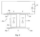
- FIG. 6 is a simplified diagrammatic illustration of the structure of the thermocouple elements that form the thermoelectric heat pump modules, such as shown in FIG. 5, that are used in the apparatus of the present invention
- FIG. 7 is a simplified sectional plan view taken substantially on the line 7 — 7 of FIG. 3 for illustrating the external air circulating arrangement
- FIG. 8 is simplified sectional plan view taken substantially on the line 8 — 8 in FIG. 3 for illustrating the internal air recirculating arrangement for the interior compartment.
- FIGS. 1-8 The preferred embodiment of the present invention shown in FIGS. 1-8 is illustrated as an apparatus 10 having a drawer 12 so that the apparatus may be conveniently mounted in an opening in a wall or in the front of a kitchen cabinet, similar to mounting of conventional warming ovens, but the apparatus may be constructed in other configurations, such as merely having a front door, without departing from the present invention.
- the apparatus 10 includes a double-walled housing 14 with insulation 16 between the walls on all sides, top and bottom, where possible, for reducing undesirable heat transfer between the exterior of the housing and interior compartment 18 formed within the housing 14 .
- the drawer 12 is supported in the housing 14 by rollers 20 in a conventional manner for ease in sliding the drawer 12 in and out of the interior compartment 18 .
- the front 12 a of the drawer 12 also includes insulation 16 .
- thermoelectric module thermoelectric heat pump modules 24 a and 24 b
- the thermoelectric modules 24 a and 24 b are located between the center of the housing 14 and the left and right, respectively, side walls of the housing 14 and approximately in the center in the front to back direction.
- each thermoelectric module 24 is provided with a pair of heat sinks 26 and 28 in vertically spaced relationship with the upper heat sink 26 having a multiplicity of upwardly extending fins 26 a and the lower heat sink 28 having a multiplicity of downwardly extending fins 28 a. Further, the fins 26 a and 28 a all extend in the lateral direction from right to left, as viewed in FIGS. 1, 3 , 7 , and 8 , and for the full width of the thermoelectric module 24 .
- thermoelectric module 24 includes a thermocouple heat pump device 34 sandwiched between the heat sinks 26 and 28 with a heat transfer block 36 on one or both sides. Insulation 38 also is sandwiched between the heat sinks 26 and 28 at all locations other than the location of the thermocouple heat pump device 34 .
- the heat sinks 26 and 28 are held together by screws 40 surrounded by thermal washers 42 for minimizing the heat transfer between heat sinks 26 and 28 , except through the thermocouple heat pump device 34 and heat transfer block 36 .
- thermocouple heat pump device 34 is a solid state semiconductor that may be of any conventional type and normally will be comprised of a plurality of individual thermocouples 34 a having a “p” type semiconductor material 34 b and “n” type semiconductor material 34 c, such as bismuth telluride, sandwiched between a conductor 34 d that joins the semiconductors 34 b and 34 c and conductors 34 e and 34 f that are connected to the opposite poles of a DC electrical source 44 for applying a voltage across and a current through the semiconductor materials 34 b and 34 c.
- p type semiconductor material
- n type semiconductor material
- a metalized ceramic plate 34 g is provided below conductor 34 d and another metalized ceramic plate 34 h is provided above conductors 34 e, 34 f for providing electrical insulation and thermal conduction, such as to the heat sinks 26 and 28 (not shown in FIG. 6 ).
- the positive DC voltage is applied to the n-semiconductor material 34 c, the electrons pass from the p-semiconductor material 34 b to the n type semiconductor material 34 c and heat is absorbed through the metallic ceramic plate 34 g and discharged through the metallic ceramic plate 34 h to create cold and hot sides, respectively, of the thermocouple 34 a.
- thermocouple heat pump device 34 is created that is capable of developing a substantial temperature differential across the device.
- Thermocouple heat pump devices of this type are available from various sources, such as Melcor of 1040 Spruce Street, Trenton, N. J. 08648, but it will readily appear to those skilled in the art that similar devices from other sources may be used in the present invention.
- a single thermocouple heat pump device 34 may be capable of creating a temperature differential of 70° C.
- thermocouple heat pump device does not directly represent the temperature differential that can be created in the mediums on opposite sides, such as the air on the opposite sides of the thermoelectric heat pump module 24 described above.
- a motorized impeller fan 50 is provided in an opening 52 in the lower panel 32 of the heat exchange assemblage 22 at approximately the center (left to right and front to back) for drawing area from the interior compartment 18 and drawer 12 .
- a duct 54 conducts the air from the fan 50 laterally in both directions, as shown by the arrows 56 , between and along the fins 28 a of the thermoelectric modules 24 a and 24 b where heat is absorbed from the circulating air by the fins.
- the cooled air is discharged from between the fins into laterally spaced plenums 58 and then through a plurality of openings or louvers 60 back into the interior chamber 18 and drawer 12 .
- the thermoelectric modules 24 a, 24 b and fan 50 energized, the air within interior compartment 18 is continually circulated and cooled for cooling the contents of the drawer 12 .
- thermoelectric modules 24 a and 24 b means are provided for circulating external air past the upwardly extending fins 26 a of the thermoelectric modules 24 a and 24 b.
- a pair of motorized impeller fans 62 a and 62 b are provided in the heat exchange assemblage 22 at laterally spaced locations in a level above the location of the centrally located fan 50 .
- the fans 62 a and 62 b are positioned below openings 64 a and 64 b, respectively, in the upper panel 30 for drawing in air from above the apparatus 10 .
- the air is discharged by fans 62 a and 62 b through ducts 66 a and 66 b, respectively, to and through the spaces between the upwardly extending fins 26 a on the thermoelectric modules 24 a and 24 b where the circulating external air absorbs heat from the fins that has been conducted or pumped through the thermoelectric modules by the thermocouple heat pump device 34 .
- Ducts 68 a and 68 b then conduct the heated air toward and through the rear of the apparatus 10 to discharge the air to atmosphere at a sufficient distance from the fans at 62 a and 62 b to avoid any direct recirculation of the heated air.
- the fans 62 a, 62 b and the thermoelectric heat pump modules 24 a and 24 b activated in a manner for cooling the internal chamber 18 , the fins 26 a of the heat sink 26 are continually cooled by the circulating air and the efficiency of the heat exchange assemblage 22 is maximized. While an arrangement with two fans 62 a and 62 b has been described for effectively doubling the air circulated past the heat sink fins 26 a over the quantity of air circulated past the heat sink fins 28 a to the interior compartment 18 for improving the efficiency, it will be readily understood by those skilled in the art that a single fan or more than two fans may be used.
- the front wall 70 of the drawer 12 is provided with a plurality of vent openings 70 a for allowing the fans 62 a and 62 b to draw fresh air from the room for cooling, rather than recirculating the air discharged from the ducts 68 a, 68 b and ducting may be provided for enhancing this air circulation path.
- a temperature probe 72 is provided in the apparatus, such as in the ceiling of the interior compartment 18 (see FIG. 4 ), and connected to a thermostat 74 for selectively controlling the temperature within the interior chamber 18 and drawer 12 by a selection switch 76 .
- the switch 76 may be provided with a continuously adjustable temperature control or a multiple temperature levels control, i e., high, medium, and low, for the cooling operation in which the polarity of the DC electrical source is established for cooling the interior compartment 18 and, in addition, continuous or multi-level controls for heating the compartment 18 by switching the polarity of the DC electrical source 44 .
- Other controls, such as a timer 78 also may be provided.
Abstract
Description
Claims (20)
Priority Applications (6)
| Application Number | Priority Date | Filing Date | Title |
|---|---|---|---|
| US09/659,433 US6370882B1 (en) | 2000-09-08 | 2000-09-08 | Temperature controlled compartment apparatus |
| IL14516001A IL145160A0 (en) | 2000-09-08 | 2001-08-28 | Temperature controlled compartment apparatus |
| CA002356419A CA2356419A1 (en) | 2000-09-08 | 2001-08-30 | Temperature controlled compartment apparatus |
| GB0121746A GB2371677A (en) | 2000-09-08 | 2001-09-07 | Temperature controlled compartment apparatus with thermoelectric module |
| MXPA01009093A MXPA01009093A (en) | 2000-09-08 | 2001-09-07 | Controlled temperature compartment apparatus. |
| US10/115,709 US20020121095A1 (en) | 2000-09-08 | 2002-04-03 | Controlled temperature compartment apparatus |
Applications Claiming Priority (1)
| Application Number | Priority Date | Filing Date | Title |
|---|---|---|---|
| US09/659,433 US6370882B1 (en) | 2000-09-08 | 2000-09-08 | Temperature controlled compartment apparatus |
Related Child Applications (1)
| Application Number | Title | Priority Date | Filing Date |
|---|---|---|---|
| US10/115,709 Continuation-In-Part US20020121095A1 (en) | 2000-09-08 | 2002-04-03 | Controlled temperature compartment apparatus |
Publications (1)
| Publication Number | Publication Date |
|---|---|
| US6370882B1 true US6370882B1 (en) | 2002-04-16 |
Family
ID=24645382
Family Applications (2)
| Application Number | Title | Priority Date | Filing Date |
|---|---|---|---|
| US09/659,433 Expired - Fee Related US6370882B1 (en) | 2000-09-08 | 2000-09-08 | Temperature controlled compartment apparatus |
| US10/115,709 Abandoned US20020121095A1 (en) | 2000-09-08 | 2002-04-03 | Controlled temperature compartment apparatus |
Family Applications After (1)
| Application Number | Title | Priority Date | Filing Date |
|---|---|---|---|
| US10/115,709 Abandoned US20020121095A1 (en) | 2000-09-08 | 2002-04-03 | Controlled temperature compartment apparatus |
Country Status (5)
| Country | Link |
|---|---|
| US (2) | US6370882B1 (en) |
| CA (1) | CA2356419A1 (en) |
| GB (1) | GB2371677A (en) |
| IL (1) | IL145160A0 (en) |
| MX (1) | MXPA01009093A (en) |
Cited By (23)
| Publication number | Priority date | Publication date | Assignee | Title |
|---|---|---|---|---|
| US6693260B1 (en) * | 2001-06-04 | 2004-02-17 | Spacessories Inc. | Warming apparatus |
| US20050000231A1 (en) * | 2003-07-02 | 2005-01-06 | Ju-Yeon Lee | Wearable cooler using thermoelectric module |
| US6854275B2 (en) * | 2002-08-08 | 2005-02-15 | International Business Machines Corporation | Method for cooling automated storage library media using thermoelectric cooler |
| US20070101737A1 (en) * | 2005-11-09 | 2007-05-10 | Masao Akei | Refrigeration system including thermoelectric heat recovery and actuation |
| US20070101749A1 (en) * | 2005-11-09 | 2007-05-10 | Pham Hung M | Refrigeration system including thermoelectric module |
| WO2008019805A2 (en) * | 2006-08-17 | 2008-02-21 | Oliver Gneuss | Serving device |
| US7619182B2 (en) | 2006-01-08 | 2009-11-17 | Whirlpool Corporation | Warming drawer |
| US20100088590A1 (en) * | 2008-10-07 | 2010-04-08 | Bigmachines, Inc. | Methods and apparatus for generating a dynamic document |
| US20100242523A1 (en) * | 2009-03-31 | 2010-09-30 | Todd Rubright | Electric Cooling System for Electronic Equipment |
| US20100281429A1 (en) * | 2009-04-30 | 2010-11-04 | Bigmachines, Inc. | Methods and apparatus for configuring a product using an array of configuration sets |
| US20110016889A1 (en) * | 2006-10-24 | 2011-01-27 | Bsh Bosch Und Siemens Hausgerate Gmbh | Heating apparatus having at least two thermoelectric modules which are connected in series |
| US20110183599A1 (en) * | 2010-01-26 | 2011-07-28 | Channell Commercial Corporation | Uninteruptable power supply enclosure and battery locker |
| WO2011092591A1 (en) * | 2010-01-28 | 2011-08-04 | Jairo Botia | Drawer system for pharmaceutical and medical surgical products incorporating dynamic advertising devices |
| CN101196352B (en) * | 2007-12-27 | 2011-12-21 | 左秀锦 | Minitype intelligent cold trap based on semiconductor refrigeration technology |
| US20130276465A1 (en) * | 2011-02-15 | 2013-10-24 | Lg Electronics Inc. | Refrigerator |
| US20150173527A1 (en) * | 2013-12-23 | 2015-06-25 | Hussmann Corporation | Zone cooling in a refrigerated merchandiser |
| CN105987466A (en) * | 2015-02-05 | 2016-10-05 | 青岛海尔智能技术研发有限公司 | Cold and hot air separation method of semiconductor refrigeration module |
| EP3100788A1 (en) * | 2015-06-05 | 2016-12-07 | Stratec Biomedical AG | Device, system and method for cooling a reagent compartment |
| US9524506B2 (en) | 2011-10-21 | 2016-12-20 | Bigmachines, Inc. | Methods and apparatus for maintaining business rules in a configuration system |
| US10065278B2 (en) | 2013-01-22 | 2018-09-04 | Western Industries Incorporated | Spill resistant warming drawer |
| CN110455007A (en) * | 2019-08-19 | 2019-11-15 | 山东凡迈电子科技有限公司 | A kind of vehicle-mounted attemperator |
| CN111609495A (en) * | 2020-04-17 | 2020-09-01 | 广东美的白色家电技术创新中心有限公司 | Fresh air refrigerating equipment for kitchen |
| CN111609502A (en) * | 2020-04-17 | 2020-09-01 | 广东美的白色家电技术创新中心有限公司 | Fresh air refrigerating equipment for kitchen |
Families Citing this family (21)
| Publication number | Priority date | Publication date | Assignee | Title |
|---|---|---|---|---|
| US6625991B1 (en) * | 2002-07-10 | 2003-09-30 | Delta T, Llc | Space saving food chiller |
| US7451603B2 (en) * | 2004-03-22 | 2008-11-18 | General Mills, Inc. | Portable cooled merchandizing unit |
| US20070251016A1 (en) * | 2004-12-28 | 2007-11-01 | Steve Feher | Convective seating and sleeping systems |
| US7272936B2 (en) * | 2004-12-28 | 2007-09-25 | Steve Feher | Variable temperature cushion and heat pump |
| CN100432575C (en) * | 2006-07-11 | 2008-11-12 | 陈少鹏 | Temperature control device |
| CN102135368B (en) * | 2006-10-24 | 2013-03-27 | Lg电子株式会社 | Refrigerator |
| US20090000031A1 (en) * | 2007-06-29 | 2009-01-01 | Steve Feher | Multiple convective cushion seating and sleeping systems and methods |
| GB2509207B (en) * | 2012-11-06 | 2014-11-05 | Alan Nuttall Ltd | Open fronted cabinet |
| GB201316911D0 (en) | 2013-09-24 | 2013-11-06 | Alan Nuttall Ltd | Energy saving food storage unit |
| EP3063485A1 (en) * | 2013-11-01 | 2016-09-07 | Arçelik Anonim Sirketi | Refrigerator with improved energy management mode and method for controlling the refrigerator |
| CN104776664B (en) * | 2015-05-07 | 2017-02-01 | 天津商业大学 | Multifunctional refrigeration and insulation can |
| KR20180087618A (en) * | 2017-01-25 | 2018-08-02 | 엘지전자 주식회사 | Container and Refrigerator including the same |
| CN107174008A (en) * | 2017-07-13 | 2017-09-19 | 四川云物益邦科技有限公司 | A kind of storage device for intensive archives of paper quality |
| US11788783B2 (en) * | 2017-11-07 | 2023-10-17 | MVE Biological Solutions US, LLC | Cryogenic freezer |
| US10663218B2 (en) | 2017-11-17 | 2020-05-26 | Omnicell, Inc. | Dispensing system with temperature controlled drawers |
| EP3710764A4 (en) * | 2017-11-17 | 2021-09-29 | Omnicell, Inc. | Temperature controlled dispense drawer |
| US11536506B2 (en) | 2018-09-12 | 2022-12-27 | Omnicell, Inc. | Temperature controlled dispense drawer |
| KR102454181B1 (en) * | 2017-12-19 | 2022-10-14 | 엘지전자 주식회사 | Refrigerator |
| CN112773180B (en) * | 2021-02-07 | 2021-09-14 | 广州一盒科技有限公司 | Cooking box temperature control device |
| US20230175764A1 (en) * | 2021-12-06 | 2023-06-08 | Whirlpool Corporation | Refrigerated storage structure |
| CN116133348B (en) * | 2023-04-18 | 2023-06-20 | 潍坊达创数控设备有限公司 | Temperature regulation control system of high-power server room |
Citations (7)
| Publication number | Priority date | Publication date | Assignee | Title |
|---|---|---|---|---|
| US4364234A (en) * | 1981-03-25 | 1982-12-21 | Koolatron Industries, Ltd. | Control circuitry for thermoelectric environmental chamber |
| US4782664A (en) * | 1987-09-16 | 1988-11-08 | Allied Products Corporation | Thermoelectric heat exchanger |
| US4922721A (en) * | 1989-05-01 | 1990-05-08 | Marlow Industries, Inc. | Transporter unit with communication media environmental storage modules |
| US5315830A (en) * | 1993-04-14 | 1994-05-31 | Marlow Industries, Inc. | Modular thermoelectric assembly |
| US5605047A (en) * | 1994-01-12 | 1997-02-25 | Owens-Corning Fiberglas Corp. | Enclosure for thermoelectric refrigerator and method |
| US5661978A (en) * | 1994-12-09 | 1997-09-02 | Pyxis Corporation | Medical dispensing drawer and thermoelectric device for cooling the contents therein |
| US6122918A (en) * | 1999-07-09 | 2000-09-26 | Odin Design Limited | Storage cabinet for cigars |
Family Cites Families (3)
| Publication number | Priority date | Publication date | Assignee | Title |
|---|---|---|---|---|
| US4838911A (en) * | 1987-07-24 | 1989-06-13 | Robertson William M | Video tape storage cabinet |
| US5301508A (en) * | 1992-08-14 | 1994-04-12 | Rubbermaid Incorporated | Thermoelectric portable container |
| US6022498A (en) * | 1996-04-19 | 2000-02-08 | Q2100, Inc. | Methods for eyeglass lens curing using ultraviolet light |
-
2000
- 2000-09-08 US US09/659,433 patent/US6370882B1/en not_active Expired - Fee Related
-
2001
- 2001-08-28 IL IL14516001A patent/IL145160A0/en unknown
- 2001-08-30 CA CA002356419A patent/CA2356419A1/en not_active Abandoned
- 2001-09-07 MX MXPA01009093A patent/MXPA01009093A/en active IP Right Grant
- 2001-09-07 GB GB0121746A patent/GB2371677A/en not_active Withdrawn
-
2002
- 2002-04-03 US US10/115,709 patent/US20020121095A1/en not_active Abandoned
Patent Citations (8)
| Publication number | Priority date | Publication date | Assignee | Title |
|---|---|---|---|---|
| US4364234A (en) * | 1981-03-25 | 1982-12-21 | Koolatron Industries, Ltd. | Control circuitry for thermoelectric environmental chamber |
| US4782664A (en) * | 1987-09-16 | 1988-11-08 | Allied Products Corporation | Thermoelectric heat exchanger |
| US4922721A (en) * | 1989-05-01 | 1990-05-08 | Marlow Industries, Inc. | Transporter unit with communication media environmental storage modules |
| US5315830A (en) * | 1993-04-14 | 1994-05-31 | Marlow Industries, Inc. | Modular thermoelectric assembly |
| US5315830B1 (en) * | 1993-04-14 | 1998-04-07 | Marlow Ind Inc | Modular thermoelectric assembly |
| US5605047A (en) * | 1994-01-12 | 1997-02-25 | Owens-Corning Fiberglas Corp. | Enclosure for thermoelectric refrigerator and method |
| US5661978A (en) * | 1994-12-09 | 1997-09-02 | Pyxis Corporation | Medical dispensing drawer and thermoelectric device for cooling the contents therein |
| US6122918A (en) * | 1999-07-09 | 2000-09-26 | Odin Design Limited | Storage cabinet for cigars |
Cited By (38)
| Publication number | Priority date | Publication date | Assignee | Title |
|---|---|---|---|---|
| US6693260B1 (en) * | 2001-06-04 | 2004-02-17 | Spacessories Inc. | Warming apparatus |
| US6854275B2 (en) * | 2002-08-08 | 2005-02-15 | International Business Machines Corporation | Method for cooling automated storage library media using thermoelectric cooler |
| US20050000231A1 (en) * | 2003-07-02 | 2005-01-06 | Ju-Yeon Lee | Wearable cooler using thermoelectric module |
| US20070101738A1 (en) * | 2005-11-09 | 2007-05-10 | Masao Akei | Vapor compression circuit and method including a thermoelectric device |
| US20070101749A1 (en) * | 2005-11-09 | 2007-05-10 | Pham Hung M | Refrigeration system including thermoelectric module |
| US20070101750A1 (en) * | 2005-11-09 | 2007-05-10 | Pham Hung M | Refrigeration system including thermoelectric module |
| US7752852B2 (en) | 2005-11-09 | 2010-07-13 | Emerson Climate Technologies, Inc. | Vapor compression circuit and method including a thermoelectric device |
| US20070101740A1 (en) * | 2005-11-09 | 2007-05-10 | Masao Akei | Vapor compression circuit and method including a thermoelectric device |
| US20070101739A1 (en) * | 2005-11-09 | 2007-05-10 | Masao Akei | Vapor compression circuit and method including a thermoelectric device |
| US20070101748A1 (en) * | 2005-11-09 | 2007-05-10 | Pham Hung M | Refrigeration system including thermoelectric module |
| US8307663B2 (en) | 2005-11-09 | 2012-11-13 | Emerson Climate Technologies, Inc. | Vapor compression circuit and method including a thermoelectric device |
| US20070101737A1 (en) * | 2005-11-09 | 2007-05-10 | Masao Akei | Refrigeration system including thermoelectric heat recovery and actuation |
| US7619182B2 (en) | 2006-01-08 | 2009-11-17 | Whirlpool Corporation | Warming drawer |
| WO2008019805A2 (en) * | 2006-08-17 | 2008-02-21 | Oliver Gneuss | Serving device |
| WO2008019805A3 (en) * | 2006-08-17 | 2008-04-17 | Oliver Gneuss | Serving device |
| US20110016889A1 (en) * | 2006-10-24 | 2011-01-27 | Bsh Bosch Und Siemens Hausgerate Gmbh | Heating apparatus having at least two thermoelectric modules which are connected in series |
| US8438860B2 (en) * | 2006-10-24 | 2013-05-14 | Bsh Bosch Und Siemens Hausgeraete Gmbh | Heating apparatus having at least two thermoelectric modules which are connected in series |
| CN101196352B (en) * | 2007-12-27 | 2011-12-21 | 左秀锦 | Minitype intelligent cold trap based on semiconductor refrigeration technology |
| US20100088590A1 (en) * | 2008-10-07 | 2010-04-08 | Bigmachines, Inc. | Methods and apparatus for generating a dynamic document |
| US8578265B2 (en) | 2008-10-07 | 2013-11-05 | Bigmachines, Inc. | Methods and apparatus for generating a dynamic document |
| US20100242523A1 (en) * | 2009-03-31 | 2010-09-30 | Todd Rubright | Electric Cooling System for Electronic Equipment |
| US20100281429A1 (en) * | 2009-04-30 | 2010-11-04 | Bigmachines, Inc. | Methods and apparatus for configuring a product using an array of configuration sets |
| US20110183599A1 (en) * | 2010-01-26 | 2011-07-28 | Channell Commercial Corporation | Uninteruptable power supply enclosure and battery locker |
| WO2011092591A1 (en) * | 2010-01-28 | 2011-08-04 | Jairo Botia | Drawer system for pharmaceutical and medical surgical products incorporating dynamic advertising devices |
| US20130276465A1 (en) * | 2011-02-15 | 2013-10-24 | Lg Electronics Inc. | Refrigerator |
| US9605888B2 (en) * | 2011-02-15 | 2017-03-28 | Lg Electronics Inc. | Refrigerator |
| US9524506B2 (en) | 2011-10-21 | 2016-12-20 | Bigmachines, Inc. | Methods and apparatus for maintaining business rules in a configuration system |
| US10065278B2 (en) | 2013-01-22 | 2018-09-04 | Western Industries Incorporated | Spill resistant warming drawer |
| US9737156B2 (en) * | 2013-12-23 | 2017-08-22 | Hussmann Corporation | Zone cooling in a refrigerated merchandiser |
| US20150173527A1 (en) * | 2013-12-23 | 2015-06-25 | Hussmann Corporation | Zone cooling in a refrigerated merchandiser |
| CN105987466A (en) * | 2015-02-05 | 2016-10-05 | 青岛海尔智能技术研发有限公司 | Cold and hot air separation method of semiconductor refrigeration module |
| CN105987466B (en) * | 2015-02-05 | 2020-11-24 | 青岛海尔智能技术研发有限公司 | Cold and hot air isolation mode of semiconductor refrigeration module |
| GB2539192A (en) * | 2015-06-05 | 2016-12-14 | Stratec Biomedical Ag | Device, system and method for cooling a reagent compartment |
| EP3100788A1 (en) * | 2015-06-05 | 2016-12-07 | Stratec Biomedical AG | Device, system and method for cooling a reagent compartment |
| US10335794B2 (en) | 2015-06-05 | 2019-07-02 | Stratec Se | Device, system and method for cooling a reagent compartment |
| CN110455007A (en) * | 2019-08-19 | 2019-11-15 | 山东凡迈电子科技有限公司 | A kind of vehicle-mounted attemperator |
| CN111609495A (en) * | 2020-04-17 | 2020-09-01 | 广东美的白色家电技术创新中心有限公司 | Fresh air refrigerating equipment for kitchen |
| CN111609502A (en) * | 2020-04-17 | 2020-09-01 | 广东美的白色家电技术创新中心有限公司 | Fresh air refrigerating equipment for kitchen |
Also Published As
| Publication number | Publication date |
|---|---|
| CA2356419A1 (en) | 2002-03-08 |
| GB2371677A (en) | 2002-07-31 |
| IL145160A0 (en) | 2002-06-30 |
| MXPA01009093A (en) | 2004-11-10 |
| GB0121746D0 (en) | 2001-10-31 |
| US20020121095A1 (en) | 2002-09-05 |
Similar Documents
| Publication | Publication Date | Title |
|---|---|---|
| US6370882B1 (en) | Temperature controlled compartment apparatus | |
| KR101768724B1 (en) | Refrigerator | |
| WO2020253252A1 (en) | Air-conditioning all-in-one machine for kitchen | |
| US3100970A (en) | Thermoelectrically refrigerated apparatus | |
| US3052100A (en) | Refrigeration system | |
| US3167925A (en) | Thermoelectric cooling device | |
| WO2020253254A1 (en) | Air-conditioning all-in-one machine for use in kitchen | |
| JP3199815U (en) | wine cellar | |
| KR101821097B1 (en) | Refrigerator | |
| JP2016090131A (en) | refrigerator | |
| KR100599841B1 (en) | Structure of food storage for cooling and warming | |
| JP2000320942A (en) | Refrigerator | |
| JP2017207264A (en) | Wine cellar and temperature control method | |
| JP3199891U (en) | wine cellar | |
| JP2000274913A (en) | Storage chamber | |
| WO2008082392A1 (en) | Thermoelectric hot/cold pans | |
| KR20060058350A (en) | Cooling and heating cabinet for vehicle | |
| JPH10108737A (en) | Meal serving vehicle | |
| JP3214485U (en) | wine cellar | |
| KR20050026600A (en) | Cool and hot storage device | |
| JP2000097546A (en) | Cooling storehouse | |
| KR102614571B1 (en) | Storehouse incorporated with air conditioner | |
| KR20020088279A (en) | A storage chamber with peltier element | |
| KR101946580B1 (en) | Refrigerator | |
| KR200342789Y1 (en) | Storage for cooling and warming |
Legal Events
| Date | Code | Title | Description |
|---|---|---|---|
| AS | Assignment |
Owner name: DISTINCTIVE APPLIANCES, INC., CALIFORNIA Free format text: ASSIGNMENT OF ASSIGNORS INTEREST;ASSIGNORS:ADAMSKI, JOSEPH R.;JIN, ZHIHUI;REEL/FRAME:011327/0728 Effective date: 20001201 |
|
| REMI | Maintenance fee reminder mailed | ||
| FPAY | Fee payment |
Year of fee payment: 4 |
|
| SULP | Surcharge for late payment | ||
| REMI | Maintenance fee reminder mailed | ||
| LAPS | Lapse for failure to pay maintenance fees | ||
| STCH | Information on status: patent discontinuation |
Free format text: PATENT EXPIRED DUE TO NONPAYMENT OF MAINTENANCE FEES UNDER 37 CFR 1.362 |
|
| FP | Lapsed due to failure to pay maintenance fee |
Effective date: 20100416 |
|
| AS | Assignment |
Owner name: DACOR, INC., CALIFORNIA Free format text: CHANGE OF NAME;ASSIGNOR:DISTINCTIVE APPLIANCES, INC.;REEL/FRAME:026101/0531 Effective date: 20060830 |
|
| AS | Assignment |
Owner name: CLEAR WITH COMPUTERS, LLC, TEXAS Free format text: ASSIGNMENT OF ASSIGNORS INTEREST;ASSIGNOR:DACOR, INC.;REEL/FRAME:026116/0575 Effective date: 20100814 |
|
| AS | Assignment |
Owner name: LATERAL U.S. CREDIT OPPORTUNITIES FUND, L.P., CALI Free format text: SECURITY INTEREST;ASSIGNOR:DACOR (FORMERLY DISTINCTIVE APPLIANCES, INC.);REEL/FRAME:038488/0675 Effective date: 20160506 |
|
| AS | Assignment |
Owner name: DACOR, CALIFORNIA Free format text: RELEASE BY SECURED PARTY;ASSIGNOR:LATERAL U.S. CREDIT OPPORTUNITIES FUND, L.P.;REEL/FRAME:039663/0478 Effective date: 20160907 |