US6370146B1 - Method and apparatus for non-disruptive addition of a new node to an inter-nodal network - Google Patents
Method and apparatus for non-disruptive addition of a new node to an inter-nodal network Download PDFInfo
- Publication number
- US6370146B1 US6370146B1 US09/107,152 US10715298A US6370146B1 US 6370146 B1 US6370146 B1 US 6370146B1 US 10715298 A US10715298 A US 10715298A US 6370146 B1 US6370146 B1 US 6370146B1
- Authority
- US
- United States
- Prior art keywords
- node
- inter
- nodes
- message
- nodal
- Prior art date
- Legal status (The legal status is an assumption and is not a legal conclusion. Google has not performed a legal analysis and makes no representation as to the accuracy of the status listed.)
- Expired - Lifetime
Links
- 238000000034 method Methods 0.000 title claims abstract description 45
- 230000001360 synchronised effect Effects 0.000 claims abstract description 16
- 230000004044 response Effects 0.000 claims description 28
- 230000008878 coupling Effects 0.000 claims description 22
- 238000010168 coupling process Methods 0.000 claims description 22
- 238000005859 coupling reaction Methods 0.000 claims description 22
- 238000004891 communication Methods 0.000 claims description 20
- 230000007704 transition Effects 0.000 claims description 12
- 238000010586 diagram Methods 0.000 description 13
- 230000008569 process Effects 0.000 description 8
- 238000012545 processing Methods 0.000 description 6
- 238000009434 installation Methods 0.000 description 3
- 230000008859 change Effects 0.000 description 2
- 238000013461 design Methods 0.000 description 2
- 238000001514 detection method Methods 0.000 description 2
- 230000014509 gene expression Effects 0.000 description 2
- 238000002955 isolation Methods 0.000 description 2
- 239000007787 solid Substances 0.000 description 2
- 238000012546 transfer Methods 0.000 description 2
- 230000001960 triggered effect Effects 0.000 description 2
- 230000003466 anti-cipated effect Effects 0.000 description 1
- 238000013475 authorization Methods 0.000 description 1
- 230000000903 blocking effect Effects 0.000 description 1
- 238000010276 construction Methods 0.000 description 1
- 230000000593 degrading effect Effects 0.000 description 1
- 230000000694 effects Effects 0.000 description 1
- 238000005516 engineering process Methods 0.000 description 1
- 239000000835 fiber Substances 0.000 description 1
- RGNPBRKPHBKNKX-UHFFFAOYSA-N hexaflumuron Chemical compound C1=C(Cl)C(OC(F)(F)C(F)F)=C(Cl)C=C1NC(=O)NC(=O)C1=C(F)C=CC=C1F RGNPBRKPHBKNKX-UHFFFAOYSA-N 0.000 description 1
- 230000003993 interaction Effects 0.000 description 1
- 238000012423 maintenance Methods 0.000 description 1
- 238000012986 modification Methods 0.000 description 1
- 230000004048 modification Effects 0.000 description 1
- 230000003287 optical effect Effects 0.000 description 1
- 230000011664 signaling Effects 0.000 description 1
- 238000012795 verification Methods 0.000 description 1
Images


Classifications
-
- H—ELECTRICITY
- H04—ELECTRIC COMMUNICATION TECHNIQUE
- H04L—TRANSMISSION OF DIGITAL INFORMATION, e.g. TELEGRAPHIC COMMUNICATION
- H04L69/00—Network arrangements, protocols or services independent of the application payload and not provided for in the other groups of this subclass
- H04L69/40—Network arrangements, protocols or services independent of the application payload and not provided for in the other groups of this subclass for recovering from a failure of a protocol instance or entity, e.g. service redundancy protocols, protocol state redundancy or protocol service redirection
-
- H—ELECTRICITY
- H04—ELECTRIC COMMUNICATION TECHNIQUE
- H04L—TRANSMISSION OF DIGITAL INFORMATION, e.g. TELEGRAPHIC COMMUNICATION
- H04L12/00—Data switching networks
- H04L12/54—Store-and-forward switching systems
- H04L12/56—Packet switching systems
- H04L12/5601—Transfer mode dependent, e.g. ATM
- H04L2012/5625—Operations, administration and maintenance [OAM]
- H04L2012/5627—Fault tolerance and recovery
Definitions
- the present invention relates generally to the field of telecommunications and, more specifically, to a system for expansion of a telecommunications network with minimal disruption of traffic service on the network.
- Switching capacity must be analyzed in terms of current demand and projected demand in order to find a solution that is cost effective for both present and future service. For example, assume that a developing country is in the process of building a basic telecommunications system and intends to provide service to most of its current population. Such a population is most likely geographically distributed among small areas of high density (cities) and larger areas of low density (suburban and rural). In addition, the population is probably growing, but at different rates in different areas. Thus, the challenge for a telecommunications system designer is to provide sufficient switching capacity to support satisfactory service to most or all of the population while also anticipating likely increases in future demand and providing for economical expansion.
- the patent describes an open, high speed, high bandwidth digital communications network for connecting multiple programmable telecommunications switches to form a large capacity, non-blocking switching system.
- the network is implemented using one or more inter-nodal networks which provide a medium for transferring information over the network, and a plurality of programmable switches, each of which appears as a node on the network and serves a group of ports. Additional switches (nodes) may be added to the network as desired to increase the system's switching capacity.
- Each node includes circuitry for transmitting and receiving variable-length, packetized information over the network, thus enabling each node to receive information from or transmit information to all other nodes.
- the network may carry any type of information present in the system including voice, data, video, multimedia, control, configuration and maintenance, and the bandwidth of the network may be divided or shared across various information types.
- devices or resources other than programmable switches may also act as nodes on the network, thereby gaining direct access to all information passing through the network.
- voice processing resources such as voice mail/message systems or other enhanced service platforms may, by becoming nodes, gain direct access to all ports served by the system without the need for a large central switch.
- the system's ability to transfer information of any type, in a readily usable form, at high speed across the network enables any service, feature or voice processing resource which is available at a given node to be provided to any port of the same or any other node.
- the programmable switching nodes and the other nodes on an expandable telecommunications system are connected by a physical medium.
- the physical medium When it is desired to modify an active inter-nodal network in order to enhance the services or increase the capacity provided by the system, by the inclusion of one or more additional nodes, the physical medium must be modified to accommodate an additional node. More specifically, the physical connections between the nodes in the inter-nodal network adjacent to the area to be expanded must be temporarily physically disconnected in order to connect the new node or nodes into the network. When the physical medium is disconnected, that portion of the inter-nodal network cannot, of course, carry telecommunications traffic. Typically, in such a case, the system, in whole or in part, must be taken out of service, thus leading to possibly unacceptable levels of service interruption.
- a new node which is added to the system must be properly configured before beginning operation to avoid undesired interference with other nodes.
- the present invention provides, in brief summary, a method and system for non-disruptive addition of one or more nodes to an active inter-nodal network in a telecommunications system.
- the invention is implemented in a method and an associated system which includes a plurality of interconnected nodes, which may be nodes used for telecommunications switching, or other nodes used for voice processing resources such as voice mail/messaging and the like.
- the nodes are interconnected by an inter-nodal network which carries packetized information among all the nodes served by the inter-nodal network.
- Each node has an open mode of operation and a special mode of operation referred to as loopback mode. More specifically, each node has an “A” I/O port, which has its own transmit and receive coupling, and a “B” I/O port, which has its own transmit and receive coupling.
- A I/O port
- B I/O port
- packets traverse between the node and the inter-nodal network by coming into the node through the receive coupling of the “A” port and exiting the node by the transmit coupling of the “B” I/O port.
- one of the I/O ports is effectively disconnected from the system while the other “loops back” and functions to both transmit and receive packets using its own transmit and receive coupling and an alternate communication path to continue to pass packets onto and receive packets from the inter-nodal network.
- a host is connected in communicating relationship with at least one of the nodes in the system.
- the host controls certain aspects of the system's operations by sending messages addressed to all nodes or specific messages to individual nodes.
- the system is also configured so that one of the nodes is a master node.
- the master node is capable of sending control messages addressed to the other, non-master, nodes in the network.
- the master does this messaging, in part, by using a unique inter-nodal network control word.
- the inter-nodal network control word is a set of bits contained within a frame which in turn contains one or more packets originating from a particular node.
- a unique messaging sequence involves an interplay between messages issued by the host, which may be controlled by a user, and messages issued in turn by the master node, using the inter-nodal network control word.
- the inter-nodal network control word allows nodes to receive and execute instructions in a synchronized manner while avoiding the necessity of forcing the host to attempt to simultaneously communicate with multiple nodes.
- a non-master node will be enabled to write into the inter-nodal network control word to communicate certain types of information to the master node. This is also a time-saving technique which can by utilized to avoid interruption of system operation.
- a location is selected along the inter-nodal network to connect one or more new nodes.
- new node shall include one or more new nodes which can be programmable switching nodes, voice processing resource nodes, or other nodes, or a combination thereof as desired in a particular application.
- the two nodes in the active system which are adjacent to the selected location are identified.
- the two nodes between which the new node is to be added shall be referred to herein as the “neighbor” nodes, as they will neighbor the new node when it is added to the system.
- the new node is prepared by the host for addition to the network by being programmed with instructions about the installation procedure it needs to follow.
- the inter-nodal network is then checked to ascertain whether any existing nodes are coincidentally operating in loopback mode. If no existing nodes are operating in loopback mode, the expansion of the system by the addition of the new node may continue. If, on the other hand, there is a node operating in loopback mode, then the fault or other condition causing that node to operate in loopback mode will have to be resolved first. This is because performing the installation procedure while any node is concurrently operating in loopback mode could cause other nodes to become isolated, and thus, cause interruption of service.
- the host issues a message addressed to the master node, instructing it to notify the two neighbor nodes, using the inter-nodal network control word, to begin a first synchronized routine to change their respective I/O ports to operate in loopback mode after a predetermined time delay. After this predetermined time period elapses, both neighbor nodes change their respective ports to operate in loopback mode essentially simultaneously. Accordingly, packetized information traversing the inter-nodal network continues to travel through the network uninterrupted except for that portion of the inter-nodal network between the two neighbor nodes. That portion is now temporarily isolated and inactive. Thus, the physical disconnection of that portion of the inter-nodal network can now take place without interruption of the remainder of the network. Thereafter, the new node or nodes are physically connected into the network.
- the new node follows a sequence of instructions, triggered by certain host-issued messages, which causes the node to wait while the inter-nodal network, which continues to carry normal traffic, is configured to include the new node.
- This sequence of instructions is a short cut around the normal sequence of messages which would be followed by a node when an inter-nodal network is being brought into service and initialized.
- the new node follows the short cut instructions so that it enters the network in a running state as if it had always been in the network. This avoids the new node following its pre-programmed instructions for network initialization.
- the two neighbor nodes After the new node is connected into the inter-nodal network and the configurations tasks are accomplished, the two neighbor nodes must return to the open mode of operation out of loopback mode. In a manner similar to the sequence followed to place the two neighbor nodes into loopback mode, both nodes must be brought out of loopback mode approximately simultaneously. Otherwise, if one node returns its respective port to normal mode first, this leaves only one node operating in loopback mode, and the network will not function properly.
- a message is issued by the host, addressed to the master node, instructing it to notify the two neighbor nodes to commence a second synchronized routine, this time to discontinue loopback mode and return to open mode after a predetermined time delay.
- the predetermined time delay allows both nodes to receive the instruction and begin the timing sequence prior to either one of them returning to the open mode of operation. In this way, both neighbor nodes, between which the new node is now inserted, return to open mode essentially simultaneously.
- the host sends a message to the new node in response to which the new node attempts to verify that it is recognizable by the master node.
- the new node does this by sending a message to the master node, using the inter-nodal network control word.
- the new node waits for an acknowledgment from the master node. When the acknowledgment is received, then a final verification is performed to ascertain that the new node or nodes as well as the neighbor nodes have open ports. Thereafter, the new node can be configured to transmit and receive packets to and from the inter-nodal network, or to perform a redundancy function by being configured in a receive only mode, as desired in the application.
- FIG. 1A is a schematic diagram of an expandable telecommunications system which employs a single inter-nodal network to transfer information among nodes;
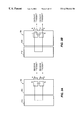
- FIG. 1B is a schematic diagram of the system of FIG. 1A also depicting a new node to be added to the system and the two nodes adjacent to the new nodes operating in loopback mode in accordance with a preferred embodiment of the present invention
- FIG. 1C is a schematic diagram of the system of FIG. 1A expanded in accordance with the present invention by the addition of a new node;
- FIG. 2 is a block diagram which illustrates the telecommunications system and the I/O ports of each node in the system, also illustrating the operation of the neighbor nodes during the installation procedure of a new node;
- FIGS. 3A and 3B are block diagrams which illustrate the open mode of operation and a loopback mode of operation of a node
- FIG. 4 is a block diagram illustrating a preferred embodiment of a frame structure which includes the inter-nodal network control word
- FIG. 5 is a message flow diagram which illustrates certain aspects of the messaging sequence used to place the two neighbor nodes in a loopback mode of operation when a non-master node initially received the operative host-issued message;
- FIG. 6 is a timing diagram which illustrates the time relationship of certain messaging sequences
- FIG. 7 is a message flow diagram which illustrates certain aspects of the messaging sequence used to place the two neighbor nodes in a loopback mode of operation when the master node initially receives the operative host-issued message;
- FIG. 8 is a flow diagram illustrating the logical states in which a new node operates while being added to the system
- FIG. 9 is a message flow diagram which illustrates the expand network messaging sequence when a non-master node receives the initial message from the host about expanding the inter-nodal network.
- FIG. 10 is a message flow diagram which illustrates the expand network messaging sequence when the master node receives the initial message from the host about expanding the network.
- FIG. 1A shows a large capacity, expandable, fully programmable telecommunications switching system 2 . Details of the construction and operation of the system 2 may be found in the above-cited U.S. Pat. No. 5,544,163. To aid in understanding of the present invention, certain aspects of the system 2 are discussed here.
- the telecommunications system 2 comprises a host 4 , and three nodes, 6 a through 6 c, connected in communicating relationship by an inter-nodal network 12 .
- nodes being either programmable switching nodes or other types of non-switching (e.g., voice processing or communications services) nodes or bridge nodes may be used in essentially any combination in the system 2 .
- node 6 d may be of any type that is compatible with inter-nodal network 12 .
- FIG. 1 B The new node 6 d may be of any type that is compatible with inter-nodal network 12 .
- FIG. 1C illustrates new node 6 d as it is incorporated into the system while the nodes proximate to it, node 6 a and node 6 c are in loopback mode as schematically illustrated in FIG. 1C by looped back port 7 on node 6 a and looped back port 9 on node 6 c.
- FIG. 2 illustrates in greater detail the telecommunications system 2 .
- the inter-nodal network 12 is configured for providing high speed digital communications among nodes 6 a through 6 c as represented by the solid line 12 a.
- the node 6 a includes a host interface which is connected in communicating relationship with the host 4 by a local area network (LAN) such as Ethernet or some other communication link 8 .
- LAN local area network
- the node 6 a may receive messages from the host 4 which are intended for one of the other nodes and pass such messages to the appropriate node over the inter-nodal network 12 a.
- Other types of host/node interfaces may be used instead of or in addition to the LAN/link 8 .
- one or more of the remaining nodes 6 b and 6 c may also be directly connected in communicating relationship with the host 4 via LAN/link 8 (not shown). In the absence of a direct link from the host 4 to each of nodes 6 b and 6 c, such nodes are preferably connected in communicating relationship with node 6 a in such fashion as to allow messages to be transmitted to and received from host 4 .
- the inter-nodal network 12 is preferably implemented using one or more fiber optic rings. However, the inter-nodal network 12 may also be implemented with any suitable communication network, such as, for example, wide area networks, wireless communications networks, the PSTN, ATM, SONET and the Internet.
- any suitable communication network such as, for example, wide area networks, wireless communications networks, the PSTN, ATM, SONET and the Internet.
- the overall operation of the system 2 is controlled by the host 4 , which is commonly implemented with a personal computer (PC), workstation, fault tolerant or other computer on which a user's application software runs.
- the host 4 communicates with the nodes 6 a through 6 c by exchanging messages over the LAN/link 8 .
- the messages are typically used to configure the nodes as well as to direct call processing functions such as making connections and providing communication services (i.e., tone detection, tone generation and conferencing).
- a host can be implemented as a printed circuit card that is physically connected within a node, or it may be an external host.
- Each of the nodes 6 a through 6 c may include interfaces 10 a through 10 c with the public switched telephone network (PSTN) (not shown) or a private network (not shown).
- PSTN public switched telephone network
- private network is intended in a broad sense to refer to any network or line or other interface other than the PSTN.
- Network/line interfaces 10 a through 10 c may terminate either digital networks or analog trunks/lines, or combinations of both types.
- the network/line interfaces of a given node may include suitable interfaces for performing telecommunications using ATM, Signaling System 7 (SS7), ISDN, T1-Robbed Bit, E1-CAS, TCP/IP or other communications protocols.
- each of the nodes of 6 a through 6 c includes two I/O ports, denoted A and B, which are physically interfaced with the inter-nodal network 12 a.
- each of nodes 6 a through 6 c receives packetized information through port A and transmits packetized information to the other nodes through port B as indicated by the solid arrows.
- FIGS. 3A and 3B An alternative mode of operation, the loopback mode, may be understood with reference to FIGS. 3A and 3B.
- packetized information is received from the inter-nodal network 12 (not shown in FIG. 3A) at port A of a network I/O card 40 a and is passed through to a nodal switch 44 a of node 6 a.
- Information originating from the nodal switch 44 a within node 6 a is passed through the network I/O card 40 a and then transmitted by way of port B as shown in FIG. 3 A.
- information passing between the nodal switch 44 a and the inter-nodal network 12 passes in one direction only, through each of ports A and B.
- port A is effectively disconnected from the inter-nodal network 12 while port B functions to both receive and transmit information.
- packets still pass through the node 6 a.
- a particular node may operate in loopback mode as to a certain port in response to a message from the host or a detection of any number of conditions on the inter-nodal network 12 , such as either a fault, or during initialization of the system.
- a frame 50 contains at least one packet 54 and may contain additional packets 58 , 60 for carrying data, address and control information over the inter-nodal network 12 .
- the maximum number of packets frame 50 may contain is a largely function of the bandwidth of the inter-nodal network 12 .
- frame 50 may contain up to thirty packets.
- Each frame 50 begins with an inter-nodal network control word 64 which is preferably a 16-bit entity.
- Control word 64 is used to effect certain control functions with respect to a node which either receives the control word or transmits it to another node.
- the master node will use the control word 64 to direct a non-master node to perform a particular control function.
- non-master nodes may use the control word 64 to communicate with the master node.
- Each packet 54 , 58 , 60 contains a start-of-packet (SOP) entity 66 , a source address (SRC) 68 , which is preferably a logical node identification (ID) of the node from which frame 50 originates, a destination address (DST) 70 , which is preferably a logical node ID of the node to which the frame 50 is destined.
- SOP start-of-packet
- SRC source address
- DST destination address
- a payload 72 which, in the illustrative embodiment, has a capacity of 512 bytes of data.
- An end-of-packet (EOP) entity 74 follows the payload 72 .
- the end of frame 50 is represented by an end-of-transmission (EOT) entity 78 .
- FIG. 2 Details of a messaging sequence followed in accordance with the present invention when a node, such as the node 6 d (FIG. 2 ), is to be added to an active inter-nodal network 12 will now be described. Assume that the inter-nodal network 12 has been appropriately configured and initialized and is now carrying data among nodes 6 a - 6 c. Further assume that one of those nodes has become a master node through an arbitration process described in U.S. Pat. No. 5,923,643, referenced above. For this example, we will assume that node 6 b is the master node.
- the host 4 already has this information as a result of being automatically notified by any node when that node has gone into loopback mode for any reason (i.e., fault isolation, node addition in progress, etc.) If there is a node with a looped back port, it should first be restored to open mode before proceeding further with the process of adding a new node. Otherwise, there is a risk that a node may become isolated when the two neighbor nodes adjacent to the position selected for the new node loop back their respective ports.
- the host 4 begins the process of adding a new node by issuing a LOOPBK_PORT message 80 a which is received by a system monitor (SYM) task 81 running on non-master node 6 a.
- SYM system monitor
- the SYM 81 issues a LOOPBK_PORT message 80 b to a ring configure (RCFG) task 83 , which in turn issues a LOOPBK_PORT message 80 c to a ring control (RCTL) task 85 running on the non-master node 6 a.
- RCFG ring configure
- RCTL ring control
- This message and the others shown with solid arrows are messages which pass between processes internal to a node or they are API (Application Program Interface) messages issued or received by the host.
- the messages shown with a dashed line are messages which are sent, using control word 64 , over the inter-nodal network 12 .
- the RCTL task 85 In response to the LOOPBK_PORT message 80 c, the RCTL task 85 , using control word 64 , passes a LOOPBK_LOOP_BACK_Indication message 84 a to the master node 6 b over the inter-nodal network 12 . As a result of receiving the LOOPBK_LOOP BACK_Indication message 84 a, the master node 6 b is informed that the neighbor nodes are to be instructed to loop back their respective ports.
- this message is preferably sent continuously until the non-master node 6 a (sending the message) receives a LOOPBK_LOOP_BACK_ACK 84 b from the master node 6 b.
- the non-master node 6 a will stop sending any messages using the network control word 64 . This allows the master node 6 b to be the only node in the network which controls the contents of the control word 64 . If the non-master node 6 a does not receive the acknowledgment from the master node 6 b, it will notify the host 4 that there has been an interruption in the procedure.
- the master node 6 b does send the acknowledgment and takes control of the control word 64 , it is programmed to thereafter start sending the LOOPBK_PREPARE_LOOP BACK message 85 a, again using control word 64 . This message is sent to the neighbor nodes between which the new node is to be added.
- the LOOPBK_PREPARE_LOOP BACK message 85 a is sent by the master node, as indicated by reference numeral 89 , preferably continuously for approximately 200 ms to be sure that both neighbor nodes receive it. (It should be noted that acknowledgment messages are omitted from FIG. 6 for purposes of improved clarity.)
- the neighbor nodes initialize a timing procedure during which the nodes read the control word 64 approximately every 250 microseconds, as indicated by reference numeral 90 . This is to ensure that the neighbor nodes will react quickly to the anticipated instructions from the master node 6 b.
- each node 6 b will receive this message with a maximum of Ims delay, as they read the control word 64 as indicated by reference numeral 92 .
- each node will preferably schedule the transition of the operating mode of its respective I/O port from open to loopback mode in approximately 2 ms. This 2 ms delay allows both nodes to receive the instruction before either one of them actually transitions to loopback mode. Otherwise, one of the nodes might receive the message and immediately loop back its port thereby possibly causing the other node never to receive the loop back instruction.
- the master node After a 2 ms delay, the master node sends a LOOPBK_LOOP BACK_COMPLETED message 87 using control word 64 .
- the two neighbor nodes are programmed to wait for the message 87 . If the neighbor nodes do not receive it within a certain time period, then they will notify the host of a problem. Otherwise, after that time period, the non-master node 6 a informs the host 4 of the successful completion of this phase of the process via messages 88 a, 88 b and 88 c of FIG. 5 . At this point, port “A” of node 6 a and port “B” of node 6 c are operating in loopback mode.
- FIG. 7 illustrates the case in which the master node 6 b is the node that receives the initial loop back port message 80 a from the host 4 because it is one of the neighbor nodes in that instance.
- the initial messaging sequence in which the message 80 a passes to the SYM 81 task which in turn passes message 80 b to the RCFG 83 task, and ultimately to the RCTL 85 task is the same as that described with reference to FIG. 5 .
- the LOOPBK_LOOP_BACK_Indication and LOOPBK_ACK sequence does not need to be followed because the master node 6 b has been notified directly by the host 4 and the master node 6 b simply sends the LOOPBK_PREPARE_LOOP BACK message 85 in order to begin the synchronized routine for the two neighbor nodes in that instance to loop back their respective ports simultaneously.
- the master node waits for the acknowledgement ACK message 85 b from the non-master, and it also waits for its own ACK message 85 b ′. Assuming that such acknowledgments are received, the process continues in the manner described herein.
- both neighbor nodes such as the neighbor nodes 6 a and 6 c of FIG. 2
- the physical connection of the new node 6 d into the network 12 can take place.
- the new node 6 d must be prepared, however, for entry into an active inter-nodal network. It is desired that the new node 6 d operate as if it had always been part of the network 12 .
- the new node 6 d is programmed in accordance with the present invention to short cut the normal sequence of operating states through which it would otherwise transition and, instead, to follow a special sequence of states until it is in a running state and the network 12 is ready to include it.
- FIG. 8 is a state transition diagram illustrating the states in which the new node 6 d will remain while both it and the network 12 are prepared for its addition thereto.
- the new node 6 d is powered on and begins operations in the RESET state designated in step 93 . It is typically configured in hardware to immediately begin to look for an external connection by checking for light (i.e., the presence of an optical signal) on its “A” and “B” I/O ports.
- the new node 6 d is connected, typically by an Ethernet interface, to the host 4 . (FIG. 2 ).
- the system software needed to operate the node on the network is then down-loaded into an appropriate storage device within the node.
- the new node 6 d is then preferably assigned, by the host 4 , a unique logical node ID which will identify it on the network 12 , as described in U.S. Pat. No. 5,923,643, referenced herein.
- a message is then issued by the host 4 , which may be controlled by a user, to cause the new node to perform a diagnostic check, as desired in the particular circumstances. This is designated in FIG. 8 by the message box 95 entitled MSG: RIC_DIAGNOSTICS. Diagnostic sequences may then be run to check the operation of the node 6 d. Any diagnostics should be run before the new node 6 d is brought into service on the network to prevent undesirable service interruption.
- the node After performing all diagnostic tasks triggered by the RIC-DIAGNOSTICS message 95 , the node waits for configuration messages in the GET CONFIG state 96 . Normally, upon receipt of such information, a node would automatically move to the ESTABLISH CLOCKWISE state 98 and through the remaining states 98 through 104 , in the normal sequence of events. However, in accordance with the invention, a message is then issued by the host 4 entitled MSG: PREPARE_FOR_ADDITION 106 , which causes the node 6 d to operate on an alternative path in which it transitions to the WAIT — FOR_CONFIG_IN_ADDITION state 108 . This is a short cut from the normal sequence of states several of which are illustrated by example in steps 98 through 104 of FIG. 8 .
- the new node 6 d will wait in the state 108 until it receives configuration information from the host 4 . Before the host provides such information, however, it is preferred that the new node 6 d is checked to ascertain that both of its I/O ports are open, that its transmitters are disabled in hardware, (this is so that the node cannot begin transmitting onto the network until it is desired that it do so), and that the diagnostic checks have been successful. Now, the configuration messages may be sent by the host 4 as indicated by block 110 in FIG. 8 .
- These configuration messages will preferably include the following elements: a logical network identification, as there may be more than one network in the system 2 , an indication that the new node is configured for the transmit mode (which becomes effective only after subsequent authorization as described hereinafter), and the number of packets, such as the packets described with reference to FIG. 4, it will use.
- a logical network identification as there may be more than one network in the system 2
- an indication that the new node is configured for the transmit mode which becomes effective only after subsequent authorization as described hereinafter
- the number of packets such as the packets described with reference to FIG. 4, it will use.
- the new node 6 d is ready to be brought into service on the inter-nodal network 12 . It has been prepared and is waiting in its WAIT FOR ADDITION 112 state. Consequently, the two neighbor nodes 6 a and 6 c (FIG. 2) should now be returned in synchronized fashion to open operating mode.
- the re-opening of the looped back ports in the neighbor nodes is managed in a manner similar to the sequence followed to place the nodes in loop back mode.
- a non-master node such as the node 6 a in FIG. 2
- the host 4 issues an EXPAND_NETWORK message 120 a which is received by the SYM task 81 on node 6 a.
- the SYM task 81 sends an EXPAND_NETWORK message 120 b to the RCFG task 83 , which in turn sends message 120 c to the RCTL task 85 of the non-master node.
- the RCTL task 85 uses the control word 64 , passes an EXPNTK_EXPAND_IND 126 a to the master node 6 b.
- the master node 6 b then sends an EXPNTK_EXPAND_ACK message 126 b acknowledging receipt of message 126 a from node 6 a.
- the non-master node 6 a stops sending any messages using the inter-nodal network control word 64 . This allows the master node 6 b to have sole use of control word 64 .
- the master node 6 b then sends a EXPNTK_PREPARE_OPEN message 128 a.
- the master node sends the EXPNTK_PREPARE_OPEN message 128 a continuously for approximately 200 ms to allow both neighbor nodes to receive it. Once the neighbor nodes receive that message, they acknowledge it with messages 128 b.
- both neighbor nodes receive message 128 a, they initialize a timing procedure similar to that previously described to read control word 64 every 250 microseconds, to allow for a quick response time.
- the master node 6 b then immediately sends the EXPNTK_OPEN_PORT message 130 .
- the two neighbor nodes schedule the opening of their looped back ports in 2 ms.
- the master node starts to send the EXPNTK_COMPLETED message 132 .
- the neighbor nodes now with their respective I/O ports open, read control word 64 until each node receives the EXPNTK_COMPLETED message 132 . This verifies that the inter-nodal network is intact.
- FIG. 10 illustrates a messaging sequence which may be used when it is the master node that receives the message from the host 4 because it is one of the neighbor nodes in that instance.
- the master node can immediately begin to send the EXPNTK_PREPARE_OPEN message 128 a to begin the synchronized routine which then proceeds in the same manner as discussed with reference to FIG. 9 .
- any node on the inter-nodal network 12 there are no looped back I/O ports in any node on the inter-nodal network 12 .
- that node In order to enable the new node 6 d to come into service (e.g., make connections, etc.), that node must transition to the RUNNING state 116 (FIG. 8 ).
- the new node 6 d will attempt to verify that it is visible on the inter-nodal network 12 by writing its node identification (ID) into the control word 64 .
- ID node identification
- the master node 6 b receives the control word 64 containing the node ID for the new node, it returns that node ID in the control word 64 as an acknowledgment.
- the new node 6 d When the new node 6 d receives its own node ID back from the master node 6 b, it then configures its transmitter to transmit, if it has previously been instructed to do so by the host during the configuration step. The new node 6 d then transitions to the RUNNING state 116 and is now in service on the inter-nodal network 12 .
- the foregoing arrangement may be used to add more than one node to an inter-nodal network at one time without an interruption of service, so long as only one break is made in the inter-nodal network.
Abstract
Description
Claims (33)
Priority Applications (8)
| Application Number | Priority Date | Filing Date | Title |
|---|---|---|---|
| US09/107,152 US6370146B1 (en) | 1998-06-29 | 1998-06-29 | Method and apparatus for non-disruptive addition of a new node to an inter-nodal network |
| PCT/US1999/014615 WO2000001130A1 (en) | 1998-06-29 | 1999-06-28 | Method and apparatus for non-disruptive addition of a new node to an inter-nodal network |
| JP2000557599A JP2002519947A (en) | 1998-06-29 | 1999-06-28 | Method and apparatus for non-destructively adding new nodes to an inter-node network |
| CA002334972A CA2334972C (en) | 1998-06-29 | 1999-06-28 | Method and apparatus for non-disruptive addition of a new node to an inter-nodal network |
| AU48395/99A AU749265B2 (en) | 1998-06-29 | 1999-06-28 | Method and apparatus for non-disruptive addition of a new node to an inter-nodal network |
| DE69922200T DE69922200T2 (en) | 1998-06-29 | 1999-06-28 | METHOD AND DEVICE FOR TROUBLE ADDING FROM A NEW NODE TO A NODE NETWORK |
| EP99931995A EP1092308B1 (en) | 1998-06-29 | 1999-06-28 | Method and apparatus for non-disruptive addition of a new node to an inter-nodal network |
| AT99931995T ATE283600T1 (en) | 1998-06-29 | 1999-06-28 | METHOD AND APPARATUS FOR EFFECTIVELY ADDING A NEW NODE TO A NODE NETWORK |
Applications Claiming Priority (1)
| Application Number | Priority Date | Filing Date | Title |
|---|---|---|---|
| US09/107,152 US6370146B1 (en) | 1998-06-29 | 1998-06-29 | Method and apparatus for non-disruptive addition of a new node to an inter-nodal network |
Publications (1)
| Publication Number | Publication Date |
|---|---|
| US6370146B1 true US6370146B1 (en) | 2002-04-09 |
Family
ID=22315111
Family Applications (1)
| Application Number | Title | Priority Date | Filing Date |
|---|---|---|---|
| US09/107,152 Expired - Lifetime US6370146B1 (en) | 1998-06-29 | 1998-06-29 | Method and apparatus for non-disruptive addition of a new node to an inter-nodal network |
Country Status (8)
| Country | Link |
|---|---|
| US (1) | US6370146B1 (en) |
| EP (1) | EP1092308B1 (en) |
| JP (1) | JP2002519947A (en) |
| AT (1) | ATE283600T1 (en) |
| AU (1) | AU749265B2 (en) |
| CA (1) | CA2334972C (en) |
| DE (1) | DE69922200T2 (en) |
| WO (1) | WO2000001130A1 (en) |
Cited By (22)
| Publication number | Priority date | Publication date | Assignee | Title |
|---|---|---|---|---|
| US20020083187A1 (en) * | 2000-10-26 | 2002-06-27 | Sim Siew Yong | Method and apparatus for minimizing network congestion during large payload delivery |
| US20020131423A1 (en) * | 2000-10-26 | 2002-09-19 | Prismedia Networks, Inc. | Method and apparatus for real-time parallel delivery of segments of a large payload file |
| US20030007461A1 (en) * | 2001-05-15 | 2003-01-09 | Priscilla Chen | Procedures for merging the mediation device protocol with a network layer protocol |
| US20030020976A1 (en) * | 2001-07-18 | 2003-01-30 | Murali Krishnaswamy | Method and apparatus for automatic port interconnection discovery in an optical network |
| US20030123486A1 (en) * | 2001-12-31 | 2003-07-03 | Globespanvirata Incorporated | System and method for utilizing power management functionality between DSL peers |
| US20030235158A1 (en) * | 2001-03-09 | 2003-12-25 | Chung-Chieh Lee | Protocol for a self-organizing network using a logical spanning tree backbone |
| US20040003111A1 (en) * | 2001-04-20 | 2004-01-01 | Masahiro Maeda | Protocol and structure for self-organizing network |
| US20040018839A1 (en) * | 2002-06-06 | 2004-01-29 | Oleg Andric | Protocol and structure for mobile nodes in a self-organizing communication network |
| US20040042501A1 (en) * | 2002-05-23 | 2004-03-04 | Hester Lance Eric | Media access control and distributed data processing using mediation devices in an asynchronous network |
| US20040078483A1 (en) * | 2002-10-16 | 2004-04-22 | Raymond Simila | System and method for implementing virtual loopbacks in ethernet switching elements |
| US6732262B1 (en) * | 1999-10-08 | 2004-05-04 | Fujitsu Limited | Method and system for controlling reset of IEEE 1394 network |
| US7006434B1 (en) * | 2000-02-10 | 2006-02-28 | Ciena Corporation | System for non-disruptive insertion and removal of nodes in an ATM sonet ring |
| US20060077946A1 (en) * | 2004-09-24 | 2006-04-13 | Microsoft Corporation | Using a connected wireless computer as a conduit for a disconnected wireless computer |
| US20060250969A1 (en) * | 2005-05-06 | 2006-11-09 | Lionel Florit | System and method for implementing reflector ports within hierarchical networks |
| US7272613B2 (en) | 2000-10-26 | 2007-09-18 | Intel Corporation | Method and system for managing distributed content and related metadata |
| US20080240116A1 (en) * | 2007-03-26 | 2008-10-02 | Motorola, Inc. | Method and Apparatus for Determining the Locating of Nodes in a Wireless Network |
| US7570927B2 (en) | 2006-06-16 | 2009-08-04 | Motorola, Inc. | Decentralized wireless communication network and method having a plurality of devices |
| US7581035B1 (en) * | 2001-08-16 | 2009-08-25 | Netapp, Inc. | Non-disruptive network topology modification |
| US7603460B2 (en) | 2004-09-24 | 2009-10-13 | Microsoft Corporation | Detecting and diagnosing performance problems in a wireless network through neighbor collaboration |
| US8086227B2 (en) | 2004-09-24 | 2011-12-27 | Microsoft Corporation | Collaboratively locating disconnected clients and rogue access points in a wireless network |
| US20120017007A1 (en) * | 2002-06-19 | 2012-01-19 | Chapman William L | Robustness improvement for bandwidth communication system |
| US20120072916A1 (en) * | 2010-09-20 | 2012-03-22 | International Business Machines Corporation | Future system that can participate in systems management activities until an actual system is on-line |
Citations (5)
| Publication number | Priority date | Publication date | Assignee | Title |
|---|---|---|---|---|
| US4680753A (en) * | 1985-04-03 | 1987-07-14 | Texas Instruments Incorporated | System and method for controlling network bus communications for input-output interlocking information among distributed programmable controllers |
| US5535213A (en) * | 1994-12-14 | 1996-07-09 | International Business Machines Corporation | Ring configurator for system interconnection using fully covered rings |
| US5544163A (en) | 1994-03-08 | 1996-08-06 | Excel, Inc. | Expandable telecommunications system |
| US5923643A (en) * | 1997-02-27 | 1999-07-13 | Excel, Inc. | Redundancy, expanded switching capacity and fault isolation arrangements for expandable telecommunications system |
| US6047331A (en) * | 1997-02-19 | 2000-04-04 | Massachusetts Institute Of Technology | Method and apparatus for automatic protection switching |
Family Cites Families (6)
| Publication number | Priority date | Publication date | Assignee | Title |
|---|---|---|---|---|
| JPS6177448A (en) * | 1984-09-21 | 1986-04-21 | Fujitsu Ltd | Node switching system |
| JPS62284539A (en) * | 1986-06-02 | 1987-12-10 | Matsushita Electric Ind Co Ltd | Loop network equipment |
| JPH0340620A (en) * | 1989-07-07 | 1991-02-21 | Hitachi Ltd | Slot access system |
| JPH03241943A (en) * | 1990-02-19 | 1991-10-29 | Nec Corp | Local area network |
| JP3109601B2 (en) * | 1991-02-25 | 2000-11-20 | 日本電信電話株式会社 | Double loop transmission device |
| US6278718B1 (en) * | 1996-08-29 | 2001-08-21 | Excel, Inc. | Distributed network synchronization system |
-
1998
- 1998-06-29 US US09/107,152 patent/US6370146B1/en not_active Expired - Lifetime
-
1999
- 1999-06-28 JP JP2000557599A patent/JP2002519947A/en active Pending
- 1999-06-28 WO PCT/US1999/014615 patent/WO2000001130A1/en active IP Right Grant
- 1999-06-28 AT AT99931995T patent/ATE283600T1/en not_active IP Right Cessation
- 1999-06-28 CA CA002334972A patent/CA2334972C/en not_active Expired - Fee Related
- 1999-06-28 AU AU48395/99A patent/AU749265B2/en not_active Ceased
- 1999-06-28 EP EP99931995A patent/EP1092308B1/en not_active Expired - Lifetime
- 1999-06-28 DE DE69922200T patent/DE69922200T2/en not_active Expired - Lifetime
Patent Citations (5)
| Publication number | Priority date | Publication date | Assignee | Title |
|---|---|---|---|---|
| US4680753A (en) * | 1985-04-03 | 1987-07-14 | Texas Instruments Incorporated | System and method for controlling network bus communications for input-output interlocking information among distributed programmable controllers |
| US5544163A (en) | 1994-03-08 | 1996-08-06 | Excel, Inc. | Expandable telecommunications system |
| US5535213A (en) * | 1994-12-14 | 1996-07-09 | International Business Machines Corporation | Ring configurator for system interconnection using fully covered rings |
| US6047331A (en) * | 1997-02-19 | 2000-04-04 | Massachusetts Institute Of Technology | Method and apparatus for automatic protection switching |
| US5923643A (en) * | 1997-02-27 | 1999-07-13 | Excel, Inc. | Redundancy, expanded switching capacity and fault isolation arrangements for expandable telecommunications system |
Non-Patent Citations (2)
| Title |
|---|
| Noh T.H. et al, "Reconfiguration for Service and Self-Healing in ATM Networks Based on Virtual Paths" Computer Networks and ISDN Systems, 1997. NL, North Holland Publishing, Amsterdam, vol. 29, No. 16, p. 1857-1867, XP004107248, ISSN: 0169-7552 (1997). |
| Yang, C.S. et al., "A Reconfigurable Modular Falut-Tolerant Binary Tree Architecture" Proceedings of the International Phoenix Conference on Computers and Communications, U.S. New York, IEEE, vol. Conf 12, p. 37-41 XP000370456, ISBN 0-7803-0922-7, (1993). |
Cited By (45)
| Publication number | Priority date | Publication date | Assignee | Title |
|---|---|---|---|---|
| US6732262B1 (en) * | 1999-10-08 | 2004-05-04 | Fujitsu Limited | Method and system for controlling reset of IEEE 1394 network |
| US7006434B1 (en) * | 2000-02-10 | 2006-02-28 | Ciena Corporation | System for non-disruptive insertion and removal of nodes in an ATM sonet ring |
| US20030046369A1 (en) * | 2000-10-26 | 2003-03-06 | Sim Siew Yong | Method and apparatus for initializing a new node in a network |
| US7058014B2 (en) | 2000-10-26 | 2006-06-06 | Intel Corporation | Method and apparatus for generating a large payload file |
| US20020112069A1 (en) * | 2000-10-26 | 2002-08-15 | Sim Siew Yong | Method and apparatus for generating a large payload file |
| US7181523B2 (en) | 2000-10-26 | 2007-02-20 | Intel Corporation | Method and apparatus for managing a plurality of servers in a content delivery network |
| US20030031176A1 (en) * | 2000-10-26 | 2003-02-13 | Sim Siew Yong | Method and apparatus for distributing large payload file to a plurality of storage devices in a network |
| US7272613B2 (en) | 2000-10-26 | 2007-09-18 | Intel Corporation | Method and system for managing distributed content and related metadata |
| US6857012B2 (en) * | 2000-10-26 | 2005-02-15 | Intel Corporation | Method and apparatus for initializing a new node in a network |
| US7165095B2 (en) | 2000-10-26 | 2007-01-16 | Intel Corporation | Method and apparatus for distributing large payload file to a plurality of storage devices in a network |
| US7076553B2 (en) | 2000-10-26 | 2006-07-11 | Intel Corporation | Method and apparatus for real-time parallel delivery of segments of a large payload file |
| US20020083187A1 (en) * | 2000-10-26 | 2002-06-27 | Sim Siew Yong | Method and apparatus for minimizing network congestion during large payload delivery |
| US20020131423A1 (en) * | 2000-10-26 | 2002-09-19 | Prismedia Networks, Inc. | Method and apparatus for real-time parallel delivery of segments of a large payload file |
| US20050198238A1 (en) * | 2000-10-26 | 2005-09-08 | Sim Siew Y. | Method and apparatus for initializing a new node in a network |
| US20020083118A1 (en) * | 2000-10-26 | 2002-06-27 | Sim Siew Yong | Method and apparatus for managing a plurality of servers in a content delivery network |
| US7177270B2 (en) | 2000-10-26 | 2007-02-13 | Intel Corporation | Method and apparatus for minimizing network congestion during large payload delivery |
| US7047287B2 (en) | 2000-10-26 | 2006-05-16 | Intel Corporation | Method and apparatus for automatically adapting a node in a network |
| US20030235158A1 (en) * | 2001-03-09 | 2003-12-25 | Chung-Chieh Lee | Protocol for a self-organizing network using a logical spanning tree backbone |
| US6982960B2 (en) * | 2001-03-09 | 2006-01-03 | Motorola, Inc. | Protocol for self-organizing network using a logical spanning tree backbone |
| US20040003111A1 (en) * | 2001-04-20 | 2004-01-01 | Masahiro Maeda | Protocol and structure for self-organizing network |
| US7171476B2 (en) | 2001-04-20 | 2007-01-30 | Motorola, Inc. | Protocol and structure for self-organizing network |
| US7251222B2 (en) | 2001-05-15 | 2007-07-31 | Motorola, Inc. | Procedures for merging the mediation device protocol with a network layer protocol |
| US20030007461A1 (en) * | 2001-05-15 | 2003-01-09 | Priscilla Chen | Procedures for merging the mediation device protocol with a network layer protocol |
| US7725039B2 (en) * | 2001-07-18 | 2010-05-25 | Meriton Networks Us Inc. | Method and apparatus for automatic port interconnection discovery in an optical network |
| US20030020976A1 (en) * | 2001-07-18 | 2003-01-30 | Murali Krishnaswamy | Method and apparatus for automatic port interconnection discovery in an optical network |
| US20100098410A1 (en) * | 2001-07-18 | 2010-04-22 | Meriton Networks Us Inc. | Method and apparatus for automatic port interconnection discovery in an optical network |
| US7581035B1 (en) * | 2001-08-16 | 2009-08-25 | Netapp, Inc. | Non-disruptive network topology modification |
| US20030123486A1 (en) * | 2001-12-31 | 2003-07-03 | Globespanvirata Incorporated | System and method for utilizing power management functionality between DSL peers |
| US20040042501A1 (en) * | 2002-05-23 | 2004-03-04 | Hester Lance Eric | Media access control and distributed data processing using mediation devices in an asynchronous network |
| US7492773B2 (en) | 2002-05-23 | 2009-02-17 | Motorola, Inc. | Media access control and distributed data processing using mediation devices in an asynchronous network |
| US20040018839A1 (en) * | 2002-06-06 | 2004-01-29 | Oleg Andric | Protocol and structure for mobile nodes in a self-organizing communication network |
| US8855220B2 (en) * | 2002-06-19 | 2014-10-07 | Intellectual Ventures Fund 83 Llc | Robustness improvement for bandwidth communication system |
| US20120017007A1 (en) * | 2002-06-19 | 2012-01-19 | Chapman William L | Robustness improvement for bandwidth communication system |
| US20040078483A1 (en) * | 2002-10-16 | 2004-04-22 | Raymond Simila | System and method for implementing virtual loopbacks in ethernet switching elements |
| US8086227B2 (en) | 2004-09-24 | 2011-12-27 | Microsoft Corporation | Collaboratively locating disconnected clients and rogue access points in a wireless network |
| US7603460B2 (en) | 2004-09-24 | 2009-10-13 | Microsoft Corporation | Detecting and diagnosing performance problems in a wireless network through neighbor collaboration |
| US20060077946A1 (en) * | 2004-09-24 | 2006-04-13 | Microsoft Corporation | Using a connected wireless computer as a conduit for a disconnected wireless computer |
| US7760654B2 (en) * | 2004-09-24 | 2010-07-20 | Microsoft Corporation | Using a connected wireless computer as a conduit for a disconnected wireless computer |
| US20060250969A1 (en) * | 2005-05-06 | 2006-11-09 | Lionel Florit | System and method for implementing reflector ports within hierarchical networks |
| US8050183B2 (en) | 2005-05-06 | 2011-11-01 | Cisco Technology, Inc. | System and method for implementing reflector ports within hierarchical networks |
| WO2006121643A1 (en) * | 2005-05-06 | 2006-11-16 | Cisco Technology, Inc. | System and method for implementing reflector ports within hierarchical networks |
| US7570927B2 (en) | 2006-06-16 | 2009-08-04 | Motorola, Inc. | Decentralized wireless communication network and method having a plurality of devices |
| US20080240116A1 (en) * | 2007-03-26 | 2008-10-02 | Motorola, Inc. | Method and Apparatus for Determining the Locating of Nodes in a Wireless Network |
| US20120072916A1 (en) * | 2010-09-20 | 2012-03-22 | International Business Machines Corporation | Future system that can participate in systems management activities until an actual system is on-line |
| US8527747B2 (en) * | 2010-09-20 | 2013-09-03 | International Business Machines Corporation | Future system that can participate in systems management activities until an actual system is on-line |
Also Published As
| Publication number | Publication date |
|---|---|
| AU4839599A (en) | 2000-01-17 |
| CA2334972A1 (en) | 2000-01-06 |
| WO2000001130A1 (en) | 2000-01-06 |
| CA2334972C (en) | 2008-12-09 |
| EP1092308A1 (en) | 2001-04-18 |
| DE69922200D1 (en) | 2004-12-30 |
| ATE283600T1 (en) | 2004-12-15 |
| AU749265B2 (en) | 2002-06-20 |
| EP1092308B1 (en) | 2004-11-24 |
| JP2002519947A (en) | 2002-07-02 |
| DE69922200T2 (en) | 2005-11-10 |
Similar Documents
| Publication | Publication Date | Title |
|---|---|---|
| US6370146B1 (en) | Method and apparatus for non-disruptive addition of a new node to an inter-nodal network | |
| US4709365A (en) | Data transmission system and method | |
| US6952396B1 (en) | Enhanced dual counter rotating ring network control system | |
| US5923643A (en) | Redundancy, expanded switching capacity and fault isolation arrangements for expandable telecommunications system | |
| US5182747A (en) | Method for controlling the insertion of stations into fddi network | |
| US5291490A (en) | Node for a communication network | |
| JP2967178B2 (en) | How to reroute packet mode data connections | |
| EP1655904A1 (en) | Stack switch manager protocol with pass-through mode | |
| US6973049B2 (en) | Auto-configuration of network interfaces in a bidirectional ring network | |
| KR20080089285A (en) | Method for protection switching in ethernet ring network | |
| JP2005502268A (en) | Method for supporting SDH / SONET automatic protection switching over Ethernet | |
| US5285449A (en) | Protocol for hybrid local area networks | |
| US20070217438A1 (en) | Ring node device and method of connecting terminal to ring node device | |
| US7246168B1 (en) | Technique for improving the interaction between data link switch backup peer devices and ethernet switches | |
| US5495232A (en) | Wiring concentrator for data networks | |
| US20060013126A1 (en) | Tunnel failure notification apparatus and method | |
| EP0243590B1 (en) | Method and apparatus for establishing a limited broadcast path within an interconnection network | |
| US7317681B1 (en) | Redundancy for dual optical ring concentrator | |
| JP3844215B2 (en) | Network configuration management system, node device, network configuration management method, node device control method, and node device control program | |
| RU2113060C1 (en) | Method for switching blocks in unit which provides transmission of data packets | |
| US7518981B1 (en) | Method and system for a graceful reroute of connections on a link | |
| WO2006027824A1 (en) | Communication network system and trouble detecting apparatus | |
| CN116261166A (en) | Link detection method, public network node and storage medium | |
| JPH09284324A (en) | Atm communication system using loop-shaped bus and its change-over method | |
| JPH04242342A (en) | Node equipment for indefinite communication network |
Legal Events
| Date | Code | Title | Description |
|---|---|---|---|
| AS | Assignment |
Owner name: EXCEL SWITCHING CORPORATION, MASSACHUSETTS Free format text: ASSIGNMENT OF ASSIGNORS INTEREST;ASSIGNORS:HIGGINS, PETER;JAZWIERSKI, JAFAL J.;REEL/FRAME:009459/0963 Effective date: 19980825 |
|
| STCF | Information on status: patent grant |
Free format text: PATENTED CASE |
|
| FPAY | Fee payment |
Year of fee payment: 4 |
|
| AS | Assignment |
Owner name: EXCEL SWITCHING CORPORATION, MASSACHUSETTS Free format text: RELEASE BY SECURED PARTY;ASSIGNOR:COMERICA BANK;REEL/FRAME:019920/0425 Effective date: 20060615 Owner name: BROOKTROUT, INC, MASSACHUSETTS Free format text: RELEASE BY SECURED PARTY;ASSIGNOR:COMERICA BANK;REEL/FRAME:019920/0425 Effective date: 20060615 Owner name: EAS GROUP, INC., MASSACHUSETTS Free format text: RELEASE BY SECURED PARTY;ASSIGNOR:COMERICA BANK;REEL/FRAME:019920/0425 Effective date: 20060615 |
|
| FPAY | Fee payment |
Year of fee payment: 8 |
|
| FPAY | Fee payment |
Year of fee payment: 12 |
|
| AS | Assignment |
Owner name: OMEGA CREDIT OPPORTUNITIES MASTER FUND, LP, NEW YORK Free format text: SECURITY INTEREST;ASSIGNOR:WSOU INVESTMENTS, LLC;REEL/FRAME:043966/0574 Effective date: 20170822 Owner name: OMEGA CREDIT OPPORTUNITIES MASTER FUND, LP, NEW YO Free format text: SECURITY INTEREST;ASSIGNOR:WSOU INVESTMENTS, LLC;REEL/FRAME:043966/0574 Effective date: 20170822 |
|
| AS | Assignment |
Owner name: WSOU INVESTMENTS, LLC, CALIFORNIA Free format text: ASSIGNMENT OF ASSIGNORS INTEREST;ASSIGNOR:ALCATEL LUCENT;REEL/FRAME:044000/0053 Effective date: 20170722 |
|
| AS | Assignment |
Owner name: WSOU INVESTMENTS, LLC, CALIFORNIA Free format text: RELEASE BY SECURED PARTY;ASSIGNOR:OCO OPPORTUNITIES MASTER FUND, L.P. (F/K/A OMEGA CREDIT OPPORTUNITIES MASTER FUND LP;REEL/FRAME:049246/0405 Effective date: 20190516 |
|
| AS | Assignment |
Owner name: OT WSOU TERRIER HOLDINGS, LLC, CALIFORNIA Free format text: SECURITY INTEREST;ASSIGNOR:WSOU INVESTMENTS, LLC;REEL/FRAME:056990/0081 Effective date: 20210528 |