US6360804B1 - Hand tool for adhesive strip application - Google Patents
Hand tool for adhesive strip application Download PDFInfo
- Publication number
- US6360804B1 US6360804B1 US09/395,191 US39519199A US6360804B1 US 6360804 B1 US6360804 B1 US 6360804B1 US 39519199 A US39519199 A US 39519199A US 6360804 B1 US6360804 B1 US 6360804B1
- Authority
- US
- United States
- Prior art keywords
- strip
- channel
- tool
- cutter
- hand tool
- Prior art date
- Legal status (The legal status is an assumption and is not a legal conclusion. Google has not performed a legal analysis and makes no representation as to the accuracy of the status listed.)
- Expired - Lifetime
Links
Images


Classifications
-
- E—FIXED CONSTRUCTIONS
- E06—DOORS, WINDOWS, SHUTTERS, OR ROLLER BLINDS IN GENERAL; LADDERS
- E06B—FIXED OR MOVABLE CLOSURES FOR OPENINGS IN BUILDINGS, VEHICLES, FENCES OR LIKE ENCLOSURES IN GENERAL, e.g. DOORS, WINDOWS, BLINDS, GATES
- E06B3/00—Window sashes, door leaves, or like elements for closing wall or like openings; Layout of fixed or moving closures, e.g. windows in wall or like openings; Features of rigidly-mounted outer frames relating to the mounting of wing frames
- E06B3/66—Units comprising two or more parallel glass or like panes permanently secured together
- E06B3/673—Assembling the units
- E06B3/67326—Assembling spacer elements with the panes
- E06B3/6733—Assembling spacer elements with the panes by applying, e.g. extruding, a ribbon of hardenable material on or between the panes
-
- B—PERFORMING OPERATIONS; TRANSPORTING
- B29—WORKING OF PLASTICS; WORKING OF SUBSTANCES IN A PLASTIC STATE IN GENERAL
- B29C—SHAPING OR JOINING OF PLASTICS; SHAPING OF MATERIAL IN A PLASTIC STATE, NOT OTHERWISE PROVIDED FOR; AFTER-TREATMENT OF THE SHAPED PRODUCTS, e.g. REPAIRING
- B29C63/00—Lining or sheathing, i.e. applying preformed layers or sheathings of plastics; Apparatus therefor
- B29C63/0026—Lining or sheathing, i.e. applying preformed layers or sheathings of plastics; Apparatus therefor an edge face with strip material, e.g. a panel edge
-
- B—PERFORMING OPERATIONS; TRANSPORTING
- B29—WORKING OF PLASTICS; WORKING OF SUBSTANCES IN A PLASTIC STATE IN GENERAL
- B29C—SHAPING OR JOINING OF PLASTICS; SHAPING OF MATERIAL IN A PLASTIC STATE, NOT OTHERWISE PROVIDED FOR; AFTER-TREATMENT OF THE SHAPED PRODUCTS, e.g. REPAIRING
- B29C66/00—General aspects of processes or apparatus for joining preformed parts
- B29C66/40—General aspects of joining substantially flat articles, e.g. plates, sheets or web-like materials; Making flat seams in tubular or hollow articles; Joining single elements to substantially flat surfaces
- B29C66/41—Joining substantially flat articles ; Making flat seams in tubular or hollow articles
- B29C66/43—Joining a relatively small portion of the surface of said articles
-
- B—PERFORMING OPERATIONS; TRANSPORTING
- B29—WORKING OF PLASTICS; WORKING OF SUBSTANCES IN A PLASTIC STATE IN GENERAL
- B29C—SHAPING OR JOINING OF PLASTICS; SHAPING OF MATERIAL IN A PLASTIC STATE, NOT OTHERWISE PROVIDED FOR; AFTER-TREATMENT OF THE SHAPED PRODUCTS, e.g. REPAIRING
- B29C66/00—General aspects of processes or apparatus for joining preformed parts
- B29C66/40—General aspects of joining substantially flat articles, e.g. plates, sheets or web-like materials; Making flat seams in tubular or hollow articles; Joining single elements to substantially flat surfaces
- B29C66/47—Joining single elements to sheets, plates or other substantially flat surfaces
- B29C66/472—Joining single elements to sheets, plates or other substantially flat surfaces said single elements being substantially flat
- B29C66/4722—Fixing strips to surfaces other than edge faces
-
- B—PERFORMING OPERATIONS; TRANSPORTING
- B65—CONVEYING; PACKING; STORING; HANDLING THIN OR FILAMENTARY MATERIAL
- B65H—HANDLING THIN OR FILAMENTARY MATERIAL, e.g. SHEETS, WEBS, CABLES
- B65H35/00—Delivering articles from cutting or line-perforating machines; Article or web delivery apparatus incorporating cutting or line-perforating devices, e.g. adhesive tape dispensers
- B65H35/0006—Article or web delivery apparatus incorporating cutting or line-perforating devices
- B65H35/002—Hand-held or table apparatus
- B65H35/0026—Hand-held or table apparatus for delivering pressure-sensitive adhesive tape
- B65H35/0033—Hand-held or table apparatus for delivering pressure-sensitive adhesive tape and affixing it to a surface
-
- B—PERFORMING OPERATIONS; TRANSPORTING
- B29—WORKING OF PLASTICS; WORKING OF SUBSTANCES IN A PLASTIC STATE IN GENERAL
- B29C—SHAPING OR JOINING OF PLASTICS; SHAPING OF MATERIAL IN A PLASTIC STATE, NOT OTHERWISE PROVIDED FOR; AFTER-TREATMENT OF THE SHAPED PRODUCTS, e.g. REPAIRING
- B29C66/00—General aspects of processes or apparatus for joining preformed parts
- B29C66/01—General aspects dealing with the joint area or with the area to be joined
- B29C66/05—Particular design of joint configurations
- B29C66/10—Particular design of joint configurations particular design of the joint cross-sections
- B29C66/11—Joint cross-sections comprising a single joint-segment, i.e. one of the parts to be joined comprising a single joint-segment in the joint cross-section
- B29C66/112—Single lapped joints
- B29C66/1122—Single lap to lap joints, i.e. overlap joints
-
- B—PERFORMING OPERATIONS; TRANSPORTING
- B29—WORKING OF PLASTICS; WORKING OF SUBSTANCES IN A PLASTIC STATE IN GENERAL
- B29C—SHAPING OR JOINING OF PLASTICS; SHAPING OF MATERIAL IN A PLASTIC STATE, NOT OTHERWISE PROVIDED FOR; AFTER-TREATMENT OF THE SHAPED PRODUCTS, e.g. REPAIRING
- B29C66/00—General aspects of processes or apparatus for joining preformed parts
- B29C66/40—General aspects of joining substantially flat articles, e.g. plates, sheets or web-like materials; Making flat seams in tubular or hollow articles; Joining single elements to substantially flat surfaces
- B29C66/47—Joining single elements to sheets, plates or other substantially flat surfaces
- B29C66/474—Joining single elements to sheets, plates or other substantially flat surfaces said single elements being substantially non-flat
-
- B—PERFORMING OPERATIONS; TRANSPORTING
- B29—WORKING OF PLASTICS; WORKING OF SUBSTANCES IN A PLASTIC STATE IN GENERAL
- B29K—INDEXING SCHEME ASSOCIATED WITH SUBCLASSES B29B, B29C OR B29D, RELATING TO MOULDING MATERIALS OR TO MATERIALS FOR MOULDS, REINFORCEMENTS, FILLERS OR PREFORMED PARTS, e.g. INSERTS
- B29K2309/00—Use of inorganic materials not provided for in groups B29K2303/00 - B29K2307/00, as reinforcement
- B29K2309/08—Glass
-
- Y—GENERAL TAGGING OF NEW TECHNOLOGICAL DEVELOPMENTS; GENERAL TAGGING OF CROSS-SECTIONAL TECHNOLOGIES SPANNING OVER SEVERAL SECTIONS OF THE IPC; TECHNICAL SUBJECTS COVERED BY FORMER USPC CROSS-REFERENCE ART COLLECTIONS [XRACs] AND DIGESTS
- Y10—TECHNICAL SUBJECTS COVERED BY FORMER USPC
- Y10T—TECHNICAL SUBJECTS COVERED BY FORMER US CLASSIFICATION
- Y10T156/00—Adhesive bonding and miscellaneous chemical manufacture
- Y10T156/12—Surface bonding means and/or assembly means with cutting, punching, piercing, severing or tearing
- Y10T156/1348—Work traversing type
- Y10T156/1352—Work traversing type with liquid applying means
- Y10T156/1361—Cutting after bonding
-
- Y—GENERAL TAGGING OF NEW TECHNOLOGICAL DEVELOPMENTS; GENERAL TAGGING OF CROSS-SECTIONAL TECHNOLOGIES SPANNING OVER SEVERAL SECTIONS OF THE IPC; TECHNICAL SUBJECTS COVERED BY FORMER USPC CROSS-REFERENCE ART COLLECTIONS [XRACs] AND DIGESTS
- Y10—TECHNICAL SUBJECTS COVERED BY FORMER USPC
- Y10T—TECHNICAL SUBJECTS COVERED BY FORMER US CLASSIFICATION
- Y10T156/00—Adhesive bonding and miscellaneous chemical manufacture
- Y10T156/17—Surface bonding means and/or assemblymeans with work feeding or handling means
- Y10T156/1788—Work traversing type and/or means applying work to wall or static structure
- Y10T156/1795—Implement carried web supply
-
- Y—GENERAL TAGGING OF NEW TECHNOLOGICAL DEVELOPMENTS; GENERAL TAGGING OF CROSS-SECTIONAL TECHNOLOGIES SPANNING OVER SEVERAL SECTIONS OF THE IPC; TECHNICAL SUBJECTS COVERED BY FORMER USPC CROSS-REFERENCE ART COLLECTIONS [XRACs] AND DIGESTS
- Y10—TECHNICAL SUBJECTS COVERED BY FORMER USPC
- Y10T—TECHNICAL SUBJECTS COVERED BY FORMER US CLASSIFICATION
- Y10T156/00—Adhesive bonding and miscellaneous chemical manufacture
- Y10T156/18—Surface bonding means and/or assembly means with handle or handgrip
Definitions
- This invention relates to a manual method and apparatus for applying a flexible adhesive strip around the perimeter edge of a rigid substrate. More particularly, the present invention relates to an improved manual method and apparatus for applying an insulating edge strip onto glass sheets as part of the manufacturing process of insulating glass units.
- Insulating glass units can be manufactured using a horizontal or vertical production line.
- the advantages of vertical unit production include: higher productivity; lower equipment costs; less floor space; convenient glass handling, including; large glass sheets, easy on-line gas filling, and simpler automation of various unit production operations, including, glass feed, glass movement, unit assembly and sealant gunning.
- Adhesive strip products are typically applied with the glass in a horizontal position.
- an air flotation assembly table is typically used.
- the air flotation table features a moveable suction cup that successively rotates the glass through 90° and linearly moves the glass to a convenient position close to the perimeter edge of the table.
- the hand tool must be held in position as the glass is rotated around.
- there can be abnormal movement of the operator's body including: prolonged spinal curvature; unnatural trunk rotation, and hyperextension of the shoulder, elbow and arm. In the long term, this abnormal movement may potentially cause repetitive stress disorders and related health problems.
- the glass sheets are tilted down to a horizontal position for strip application and the strip is applied using conventional rotating tables and hand tools.
- the glass sheets For unit assembly, the glass sheets must then be tilted back into a vertical position and because of this extra glass movement, productivity is reduced.
- the adhesive strip product described in U.S. Pat. No. 4,831,799 incorporates a vapor barrier backing.
- a half circular notch is made in the spacer and this creates a flex point that allows for easy corner formation.
- Various application tools have been developed for forming these notched corners and as documented in photographs of a prototype Edgetech application tool, one way of forming these corner notches is through the use of a slidable circular punch. When activated, the hollow punch removes a half circular portion or slug of strip material. Because of the acrylic side adhesive, these slugs adhere together and as a result, the slug material can be easily ejected from the tool.
- the advantage is that the tool can remain in continuous contact with the glass and the productivity of strip application is improved.
- the tool can also incorporate a blade for cutting through the adhesive strip.
- a blade for cutting through the adhesive strip As described in U.S. Pat. No. 5,472,558 issued to Lafond, one approach is add a separate blade that operates in combination with the punch to both notch and cut through the adhesive strip at the final corner.
- the Lafond tool For operating the pneumatic cylinder, the Lafond tool also features a finger trigger that is located below a cylindrical handle and operated by means of a finger pulling action.
- a finger trigger that is located below a cylindrical handle and operated by means of a finger pulling action.
- the present invention provides a hand tool for applying adhesive strip material to a substrate having an edge and a major face, said hand tool comprising: a body having a lower surface and a channel extending therethrough adjacent said lower surface for receiving a strip of material therein; a substrate positioning member located close to said channel on said lower surface of said body for guiding said tool along said edge of said substrate, said lower surface of said body being elevated from said major face by said strip when said strip is fed through said channel; an adjustable wheel for applying pressure on said strip to urge said strip to adhere with said substrate major face; and a cutting mechanism mounted on said body, said cutting mechanism being selectively operable for partially cutting said strip and for fully cutting said strip.
- the cutting mechanism is preferably provided by a cutter and a displacement means that is selectively operable to shift relative alignment of the strip with respect to the cutter so that the cutter can partially or fully cut through the strip as desired. For example when applying a spacer strip around a rectangular glass sheet, starting at one corner and extending successively along each edge, at the second, third and fourth corners the spacer strip will be partially cut to facilitate its bending through a right angle at that corner, whereas when all four sides have been complete, the strip will be severed at the first corner.
- the cutter is in the form of a reciprocating punch or knife oriented substantially at right angles to the channel, and a displacement means is effective to displace the strip laterally in the channel so that the strip which is normally partially aligned with the cutter, but when the strip is to be severed, it is moved to become fully aligned with the cutter. It will be appreciated that the same effect can be achieved by arranging for the cutter rather than the strip to be displaceable laterally with respect to the channel.
- the cutter can be in the form of a hollow tubular punch aligned to cut an arcuate notch out of the strip to facilitate bending thereof at a corner of the substrate, but capable of alignment to fully sever the strip when required. With this arrangement the strip is bent at the corner in a direction to close up or reduce the arcuate notch.
- the cutter is in the form of a knife which partially cuts through the strip to form a slit at a location where a corner is to be formed. It will be understood that in this configuration the strip is bent so that the sides of the slit lie approximately 90° and face outwards at the corner of the substrate.
- the strip within the channel is to be laterally displaced, this is readily effected by a simple pusher element carried in the side of the body and operable to displace the strip laterally when desired. While it is possible for the pusher element to be spring loaded and to engage a U-shaped cradle in the channel through which the strip is passed, displacing this cradle laterally when the strip is to be severed, in a simpler and much cheaper arrangement it is sufficient for the pusher element to be a plastic part loosely guided in a wall of the body adjacent the channel and having a pad surface that can engage the side of the strip material and push it laterally into an extension on the opposite side of the channel.
- the pusher element is furthermore preferably designed to clamp within the channel the severed end of the strip material leading from the supply, so that the strip material does not have to be re-threaded into the tool in subsequent application operations.
- a method for use by an operator in applying an adhesive strip to a surface border area around the periphery of a rigid substrate having a flat major face may involve the steps (a) locating the substrate in a generally upright position to present said major face towards the operator; (b) providing a hand tool which is adapted for manipulation by the operator for applying said adhesive strip to said substrate; (c) supplying a continuous length of adhesive strip material from a supply to said hand tool; (d) wherein the operator manipulates said hand tool to pass along said periphery to apply said strip of adhesive material to said border surface area of said major face around the entire periphery of the substrate.
- the adhesive strip material is delivered from a reel behind the operator through an overhead guide to a discharge position above and in front of the substrate. Release liners on the strip are preferably peeled off as the strip exits from the guide.
- adhesive strip typically is applied starting at one corner and then continuously along the lengths of the four sides, the strip being notched or partially cut to facilitate its bending through 90° at each of the second, third and fourth corners, and finally severed when it is returned to the first corner.
- the starting point is typically the upper end of the left hand edge of the substrate.
- the substrate is preferably mounted so that it can be moved vertically to a preferred working height.
- use may be made of moveable suction cups which engage the substrate so that it can be adjusted vertically during application so that the instantaneous point of application of the strip is at all times conveniently located with respect to the operator.
- the body and handle of the tool are preferably ergonomically shaped for comfort in use and to allow engagement of the tool by multiple and changing hand positions.
- the punch is preferably selectively operated by the fingers or thumb of the hand in which the tool is held, suitable actuators requiring pushing action from a finger or thumb onto a lever or button.
- the components of the hand tool preferably are detachable, and the tool has a body to which the components can be attached alternatively for use in right handed or left handed mode.
- the tool includes a removable front face plate which at its lower end incorporates a slot at the top of which is a for guiding the strip into the tool channel, the face plate also including a large opening through which slugs cut from the strip by the punch are ejected.
- the lower face of the tool is preferably provided as a removable wear plate, and the positioning member as a reversible pad that is releasably attached to the lower surface of the body, these parts being of plastic material which will minimize damage to the substrate.
- the pressure wheel which rides on the strip within the tool channel is preferably height adjustable by means of a finger actuated rotatable nut carried by a threaded stem on which the pressure wheel is supported.
- FIG. 1 shows perspective views of tool manipulation at positions A, B, C, D, and E, for the application of an adhesive strip on a vertical glass sheet.
- FIG. 2 is a perspective view of the production equipment for vertical adhesive strip application.
- FIG. 3 is a side elevation view of the support module.
- FIG. 4 is a front elevation view of the support module.
- FIG. 5 is a top plan view of a liner remover.
- FIG. 6 is a top perspective view of a vacuum liner remover.
- FIG. 7 shows a series of elevation views A, B and C of a vertical application station incorporating a moveable suction cup.
- FIG. 8 shows a series of elevation views A, B and C of a vertical application station incorporating a moveable work surface.
- FIG. 9 is a top perspective detail of the adhesive strip application with a notched corner detail.
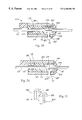
- FIG. 10 is a front cross section through the hand tool for horizontal strip application taken on the line X—X in FIG. 11 .
- FIG. 11 is a side cross section through the hand tool for horizontal strip application taken on the line XI—XI in FIG. 10 .
- FIG. 12 is a sectional plan view of the push-over block taken on the line XII—XII in FIG. 10 with the punch positioned for the removal of a portion of the adhesive strip.
- FIG. 13 is a view similar to FIG. 12 of the push-over block with punch positioned to cut-through the adhesive strip material.
- FIG. 14 is a top perspective detail of the adhesive strip application with an open-sided corner detail.
- FIG. 15 is a top perspective cross-section view of the push-over block with chisel blade positioned for partial cut-through of the adhesive strip.
- FIG. 16 is a view similar to FIG. 15 showing the chisel blade positioned for complete cut-through of the adhesive strip material.
- FIG. 17 is a cross-sectional view corresponding to FIG. 12 showing a modified hand-held tool.
- FIG. 18 is a view corresponding to FIG. 13 showing the modified tool of FIG. 17 .
- FIGS. 19 and 20 are views corresponding to FIGS. 17 and 18 respectively showing a further modified tool.
- FIG. 21 is a perspective view of a push-over block used in the tool of FIGS. 19 and 20 .
- FIG. 1 is a perspective view of the production steps required for vertical strip application using a hand tool 21 .
- the glass sheet 20 is located on a vertical work surface 22 and is positioned by the operator at a convenient working height. Generally it is easier if the adhesive spacer strip 23 is fed from above the vertical work surface 22 and that for a right handed operator, this typically means that spacer application starts at the top left corner 24 of the glass sheet 20 .
- the operator first feeds the adhesive strip 23 through a channel within a hand tool 21 and holds the adhesive strip against a back support block using the right hand 25 . Using the left hand 26 , the adhesive strip 23 is then pulled downwards creating a loop 27 that extends down to about the bottom edge 28 of the vertical glass sheet 20 . The purpose of this loop 27 is to ensure that during application, the adhesive strip 23 moves easily into the tool and is not excessively stretched.
- the tool is held in the palm 29 of the right hand 25 and is also partially supported by the left hand 26 .
- the hand positions are readjusted so that the tool handle 31 is held conventionally in the right hand 25 (See position C).
- the front face 32 and handle 31 of the tool 21 are ergonomically shaped,
- the adhesive strip 21 is then conventionally applied to the other three sides of the vertical glass sheet 20 (See positions C, D and E) and at the final corner 24 , the adhesive strip 23 is cut off.
- the adhesive strip 21 is fed from above the vertical work surface 22 , it is feasible especially with roundtop units, for adhesive strip application to start at the bottom right or left-hand corners.
- FIG. 2 shows a perspective view of part of a vertical insulated glass production line 35 incorporating a castor wheel track 36 and a vertical air-float application station 37 .
- a glass sheet 20 is located on a moveable work surface 38 and is firmly held in place using vacuum cups 33 .
- the glass sheet 20 is raised to a convenient work height by the operator 39 .
- a support module 40 supplies the adhesive strip material 23 at a central location immediately above the vertical application station 37 .
- the adhesive strip material 23 is packaged on reels and to protect the desiccant material within the adhesive strip, the reels are stored in sealed enclosures 51
- the reels are located on the support module 40 that features a double reel stand 41 , a central pivot support 42 , a pivot arm 43 , a vacuum liner remover 44 , an industrial vacuum system 45 and sound insulated box 46 .
- the support module 40 is located about four feet in front of the vertical application station 37 . Also to provide for easy loading and unloading of the reels, the double reel stand 41 is located about three to four feet above the floor level
- the vacuum liner remover 44 is centrally located just above the application station 37 .
- the vacuum liner remover 44 is supported by a pivot arm 43 that is connected to a central pivot support 42
- the adhesive strip material 23 is directed to the vacuum liner by means of guide 50
- the pivot arm 43 can be manually pivoted downwards and when released, the pivot arm 43 reverts back to its original position due to the use of a gas cylinder 48 .
- the double reel stand 41 features a reel clutch assembly 49 that is described in FIG. 4 .
- the protective liner is removed by a vacuum suction process and this is achieved by the vacuum liner remover 44 being connected by a flexible hose 49 to an electrically-powered industrial vacuum system 45 .
- One suitable industrial vacuum cleaner is a Dust Bane PC- 3 model.
- the vacuum system 45 is located within a sound insulating box 46 .
- FIG. 3 shows a side elevation view of the support module including a cut-away view of the vacuum system 45 .
- FIG. 4 shows a front elevation view of the support module including an exploded view of the double reel stand 41 , including the sealed enclosure 51 and the double reel clutch assembly 55 .
- the sealed enclosure 51 consists of a circular back plate 52 and a circular reel cover 53 incorporating a bristle-edge slot opening 54 for additional moisture protection.
- the reel clutch assembly 51 consists of a support rod (not shown), cylindrical finger bearings 56 , a spacer 57 , front and rear pressure pads 58 and a pressure knob 59 .
- FIG. 5 is a top plan view of a vacuum liner remover 44 that consists of two plastic housing sections 60 that are connected by two sets of double alignment pins 61 .
- One of the plastic housing sections 60 is fixed in position and is bolted to the liner remover support plate 63 .
- the second housing section can slide back and forth on the alignment pins 61 and this allows the spacing between the plastic sections to be easily adjusted so that light pressure can be applied by the pressure wheel 62 to the adhesive strip 23 .
- the second housing section is also bolted to the liner support plate 63 and is moveable by means of a slotted hole in the support plate 63 .
- the pressure wheels 62 feature a light durometer plastic or rubber surround. The pressure wheels 62 are connected by shoulder bolts 64 to the two plastic housing sections 60 .
- the adhesive strip passes between the two pressure wheels 62 and the flexible protective liner 65 is removed from both sides of the adhesive strip 23 using vacuum suction in combination with some mechanical action.
- the two liners 65 are peeled away from the adhesive strip 21 and are passed around the two pressure wheels 62 .
- the two liners are then respectively fed into two small openings 66 that are located tangentially to the pressure wheels 62 .
- Metal tubular connections 67 are embedded within the plastic housing sections 60 and are linked by two flexible plastic tubes 68 to a Y-connector 69 attached to single flexible vacuum hose 49 that feeds to an industrial vacuum system 45 .
- FIG. 6 shows a top perspective view of the vacuum liner remover.
- FIG. 7 shows a series of elevational views A, B, and C of a vertical application station 37 incorporating a moveable work surface 39 that is supported on a vertical sub frame assembly 70 .
- the moveable work surface 38 is connected to the two structural leg supports of 82 vertical sub frame assembly 70 using a slide bearing and linear track system (not shown).
- the vertical application station 37 incorporates a caster wheel track 36 and the moveable work surface 38 also incorporates an air float surface 71 .
- the vertical application station is typically located adjacent to a vertical washer (not shown), and the height of the caster wheel track 36 is typically the same height as the exit track from the vertical washer.
- the glass sheet 20 After the glass sheet 20 has been washed, it is transferred from the vertical washer to the vertical application station 37 with bottom glass edge 28 riding on the caster wheel track 36 .
- the glass sheet 20 is approximately centered along the moveable work surface 38 .
- the suction cups 73 are activated through operation of the center foot pedal 72 and the glass sheet 20 is firmly held in position against the work surface 38 .
- the hand tool (not shown) is positioned on the top left corner 24 of the glass sheet 20 .
- the moveable work surface 38 Through operation of the left side foot pedal 74 A, the moveable work surface 38 is raised upwards by means of a centrally located cylinder 76 that can be powered by pneumatic, hydraulic or electro-servo means.
- the adhesive strip 23 is applied to the left hand side 75 of the glass sheet 20 .
- the glass sheet 20 is stopped in position.
- the adhesive strip 23 is applied around the bottom left corner 30 of the glass sheet 20 .
- the adhesive strip 23 is then applied along the bottom edge and around the bottom right corner 77 .
- the moveable working surface 38 is then lowered and the adhesive strip 23 is applied to the right hand side 78 of the glass sheet 20 .
- the adhesive strip 23 is then applied around the top right corner and along the top edge 79 of the glass sheet 20 .
- FIG. 8 shows a series of elevational views of a vertical application station 37 incorporating a moveable suction cup 81 .
- a glass sheet 20 is centrally located on the air float work surface 71 and using a moveable suction cup 81 , the glass sheet is raised to a convenient work height for the operator.
- the glass sheet 20 is then firmly held in position using the combination of the vacuum suction cup 81 and a reversible vacuum/air system.
- an adhesive strip 23 is then applied around the perimeter edge of the glass sheet 20 . Once strip application is complete, the glass sheet 20 is then lowered back down onto the castor wheel track 36 .
- FIG. 9 shows a top perspective view of an adhesive strip application with a notched corner detail.
- a half-circular slug has been removed from the flexible adhesive strip 23 and this allows the strip to be bent or flexed about a corner 83 .
- the key advantage of this detail is that the vapor barrier backing 85 of the strip can be continuous.
- FIG. 10 shows a front cross section through a hand tool 21 for horizontal strip application.
- the body 88 is manufactured in part from a U-shaped metal channel 89 that has a lower surface 90 .
- a removable base plate 91 is attached to the U-shaped metal channel 89 .
- the base plate 91 extends over the entire lower surface 90 and the base plate is also manufactured from a smooth plastic material such as Teflon or polyacetal plastic.
- An alignment bar 92 is attached to the base plate 91 and extends the length of the lower surface 90 .
- the alignment bar 92 is also manufactured from a smooth, durable plastic that provides for sliding guided contact on the perimeter edge 93 of the glass sheet 20 . Because the plastic alignment bar 92 is subject to extensive wear, the strip is reversible and is also made from a durable plastic material such as polyacetal.
- a U-shaped cradle or push-over block 94 is positioned between the two side-walls 95 of the U-shaped metal channel 89 .
- the push-over block 94 is operated by means of a push-bar 96 to which it is connected by tubular supports 97 guided in bores in the right hand side wall.
- a removable handle 31 is held in place by the pneumatic cylinder 97 that is screwed into and supported by the U-shaped metal channel 89 .
- the cylinder 97 is centrally located on the U-shaped channel 89 and this ensures that the tool weight is balanced so that the tool can be comfortably held in the hand.
- tubing connections are kept to a minimum and this is achieved by using a spring-return type pneumatic cylinder 97 .
- the air supply line 98 is connected to a valve 100 that is located between the two side walls 9 S of the U-shaped metal channel 89 .
- a lever bar 101 is connected to the valve 100 .
- a second air line 102 connects the valve 100 to the pneumatic air cylinder 97 .
- Mounted within the cylinder 97 is a piston that moves back and forth when activated.
- the adhesive strip passes through the U-shaped push-over block 94 .
- Attached to the piston shaft 103 is a two-piece punch assembly 86 that consists of a punch block 104 and a punch knife 105 .
- the punch assembly 86 moves vertically downwards to the punch pad 106 .
- the pad is manufactured from low-friction material such as Teflon.
- FIG. 11 shows a side cross section through the hand tool for horizontal strip application. Attached to U-channel metal channel 89 is a removable front face plate 108 . During the corner-notching operation, the punch blade 105 when depressed removes a part-circular slug of material from the adhesive strip. Because of the side adhesive on the strip, the part circular slugs successively removed adhere together and form a half cylindrical tube that is ejected through a slot 109 in the front face plate 108 .
- Both sides of the front face plate 108 are smoothly contoured and direct the part-circular tube of slug material away from the glass substrate 20 .
- the front face plate 108 also incorporates a roller 110 between the side of a slot in the front face that helps to direct and hold down the adhesive strip at the entry point 121 .
- the roller 110 is manufactured from Teflon plastic.
- the adhesive strip passes beneath the roller 110 and through the U-shaped push-over block 94 .
- the strip is then channelled between laterally spaced plastic spacer pieces (not shown) and beneath an adjustable pressure wheel 113 .
- the pressure wheel 113 rides on the adhesive strip and ensures that the base plate 91 is not in direct contact with the glass sheet 20 .
- FIG. 12 shows a cross section plan view of the push-over block 94 as set up in its rest position for the corner notching operation.
- the adhesive strip 23 passes through the U-channel push-over block 94 .
- the push-over block 94 is located between the two side walls 95 of the metal U-shaped channel 89 .
- the push-over block 94 incorporates two half-circular cut-outs 154 and 155 .
- One side of the push-over block 118 is connected by the two tubular metal supports 116 that pass through a side wall 95 of the metal U-channel 89 and are connected to the push bar 96 .
- the other side of the push-over block 119 is pressed against by a spring 120 that is anchored to the adjacent side wall 95 of the metal U-channel.
- the adhesive strip 23 passes through the entry point 121 of the front face plate 108 and then passes through the U-shaped push-over block 94 .
- the punch knife 105 removes a half circular material slug 111 from the adhesive strip 23 .
- the plastic infill panels 114 and 11 S guide the adhesive strip 23 through the open channel.
- the adhesive strip 23 is then directed downwards through a slot 122 in the base plate and is then adhered to the glass substrate by means of the adjustable pressure wheel 113 .
- FIG. 13 shows a cross section plan view of the push-over block 94 as set up for the final cut-off operation.
- the plastic infill panel 114 features a chamfered corner edge 124 .
- Another key feature is that because following the cut-off operation, the adhesive strip material can be held within the tool by maintaining the block 118 displaced as shown in FIG. 13 where it presses the strip against the edge of the entry point 121 and so there is no need to rethread the adhesive strip through the open channel within the tool to start a subsequent operation.
- FIG. 14 shows a corner detail for adhesive strip application incorporating an open cut corner 121 .
- the preferred application detail is to corner notch the adhesive strip 23 .
- an alternative corner application detail is to partially cut through the back face 126 of the adhesive strip as shown in FIG. 15 .
- the barrier film 85 is not continuous, the open-cut corner 127 allows for additional sealant material to be applied at the corners and thus ensures that the edge-seal integrity of the insulating-glass unit is not downgraded.
- FIG. 15 is a top perspective cross-section view of an alternative push-over block 128 which uses a chisel blade 129 (instead of the punch blade) to produce the open cut corner 127 of FIG. 15 .
- the chisel blade 129 is attached to a blade block 130 which in turn is attached to the piston shaft 103 . When activated, the chisel blade 129 partially cuts through the back face of the adhesive strip 23 .
- FIG. 16 is also a top perspective cross-section of the push-over block 128 with a chisel blade 129 .
- the push-over block 94 is moved over and when activated, the chisel blade 129 fully cuts through the adhesive strip 23 .
- the push-bar is located on the opposite side of the tool.
- FIGS. 17 through 21 incorporate a simplified structure for effecting the push-over action of the adhesive strip 23 within the channel 89 avoiding the complexity of the U-shaped cradle or push-over block 94 and the return spring.
- the push-over block generally indicated at 161 includes a vertically elongate generally convex rectangular handle portion 162 which projects outside the tool and a block-like head 163 which is received within the tool adjacent one side of the channel 89 , the head and the handle being interconnected by a narrow vertical web 165 that is slidable horizontally within a slot 166 formed in the side wall 95 of the hand tool.
- FIG. 17 Operation of the embodiment of FIG. 17 is similar to that of FIG. 12 .
- the strip passes linearly (when viewed in a direction at right angles to the substrate) through the tool 21 . 1 so that when the punch blade 105 is actuated to form a corner notch, it cuts out a slug 110 of arcuate outline which extends only partially across the width of the strip 23 .
- the push-over block 161 is actuated by manual engagement of the handle 162 to press the head 163 laterally against the strip as illustrated in FIG. 18 .
- the strip is now in complete alignment with the punch blade so that when the latter is actuated the strip is severed.
- the vertically extending recess or groove 164 ensures that the punch blade 105 does not foul the push-over block.
- FIGS. 19, 20 and 21 are shown portions of a hand tool 21 . 2 that is similar in construction to that shown in FIGS. 15 and 16 in that instead of a tubular punch it employs a cutter in the form of a chisel or knife blade 129 .
- the action of the push-over mechanism in the embodiment of FIGS. 19 and 20 is substantially identical to that of the embodiment of FIGS. 17 and 18 except that to form a corner such as shown in FIG. 14 produced by the knife 129 , the strip 23 is turned through 90° in the opposite sense to the corner-forming operation that is done when using the tool 21 . 1 , and accordingly as compared to FIG. 17, in FIG. 19 the push-over mechanism is shown as operating from the opposite side of the tool.
- the tools illustrated are reversible, and as shown are set up for use by a right handed operative. However for a left handed operative the parts are reversed so that the push-over block actuator would be located on the opposite side of the tool from what is shown in FIGS. 10 to 20 .
- a push-over block 181 having a handle 182 extending on the exterior side of the tool and a head 183 positioned within the tool adjacent one side of the strip, is guided by a web portion 185 thereof in a narrow slot 186 of the housing to be movable transversely with respect to the strip 23 in alignment with the cutter knife 129 .
- the structure of the push-over block 181 is more fully shown in FIG. 21 .
- the block 181 is a low-cost component which can be fabricated for example in plastic material, and is small and relatively light in weight.
- Operation of the tool shown in FIGS. 19 and 20 is substantially identical to that of the tool 21 . 1 shown in FIGS. 17 and 18, and accordingly need not be described in any detail.
- the push-over block 181 When the push-over block 181 is actuated, the strip 23 is moved transversely as shown in FIG. 20 to project into a large lateral recess 180 in the plastic infill panel 115 .
- No springs or elaborate guides are required for the push-over block which is of lightweight construction, and is readily returned to the non-actuated position shown in FIG. 19, for example through the resilient force of the strip 23 which seeks to return to the straight condition.
- the push-over block is held captive by the interaction of the slot 186 with the web 185 and so cannot accidentally become detached from the tool.
- FIGS. 10 to 21 show cross sections, plans, and perspective details of the hand tool for horizontal strip application set up for operation by a right handed or left handed as the case may be person, it will be appreciated by those skilled in the art that the tool is modular in design and can be easily modified for other operations.
- the main structural support for the tool is the U-shaped metal channel. By adding on different components such as handles, front face plates, back support plates and punch pieces, the tool operation can be modified from horizontal to vertical application, from right to left-handed use and from punch blade to chisel blade function.
- FIGS. 1 to 21 when describing the product invention, specific reference is made to the adhesive strip product, Super Spacer®, manufactured by Edgetech I. G. Inc. Although the equipment has been specifically developed for this product, it should be apparent to those skilled in the art that the invention described has wide application and is not limited to this particular adhesive strip product.
Abstract
Description
Claims (16)
Priority Applications (1)
| Application Number | Priority Date | Filing Date | Title |
|---|---|---|---|
| US09/395,191 US6360804B1 (en) | 1997-03-14 | 1999-09-14 | Hand tool for adhesive strip application |
Applications Claiming Priority (4)
| Application Number | Priority Date | Filing Date | Title |
|---|---|---|---|
| CA2200024 | 1997-03-14 | ||
| CA002200024A CA2200024C (en) | 1997-03-14 | 1997-03-14 | Manufacture of insulating glass units |
| US09/042,190 US6116315A (en) | 1997-03-14 | 1998-03-13 | Manual method and related equipment for adhesive strip application |
| US09/395,191 US6360804B1 (en) | 1997-03-14 | 1999-09-14 | Hand tool for adhesive strip application |
Related Parent Applications (1)
| Application Number | Title | Priority Date | Filing Date |
|---|---|---|---|
| US09/042,190 Continuation-In-Part US6116315A (en) | 1997-03-14 | 1998-03-13 | Manual method and related equipment for adhesive strip application |
Publications (1)
| Publication Number | Publication Date |
|---|---|
| US6360804B1 true US6360804B1 (en) | 2002-03-26 |
Family
ID=25679128
Family Applications (1)
| Application Number | Title | Priority Date | Filing Date |
|---|---|---|---|
| US09/395,191 Expired - Lifetime US6360804B1 (en) | 1997-03-14 | 1999-09-14 | Hand tool for adhesive strip application |
Country Status (1)
| Country | Link |
|---|---|
| US (1) | US6360804B1 (en) |
Cited By (11)
| Publication number | Priority date | Publication date | Assignee | Title |
|---|---|---|---|---|
| US6488068B2 (en) * | 2001-01-12 | 2002-12-03 | Daimlerchrysler Corporation | Fixture for applying molding to vehicles |
| US20040187949A1 (en) * | 2003-03-26 | 2004-09-30 | Titan Umreifungstechnik Gmbh & Co. Kg | Pneumatic strapping machine |
| US20090320406A1 (en) * | 2008-06-27 | 2009-12-31 | 3M Innovative Properties Company | Applicator tool |
| SG166675A1 (en) * | 2002-10-25 | 2010-12-29 | Agc Flat Glass Na Inc | Hand application tool for laying sealant spacer strip on glass or like material |
| US20120085499A1 (en) * | 2009-10-22 | 2012-04-12 | Inova Lisec Technologiezentrum Gmbh | Device for applying spacer tape |
| US20150197076A1 (en) * | 2012-08-07 | 2015-07-16 | Erdman Automation Corporation | Single axis applicator |
| USD735009S1 (en) | 2013-07-08 | 2015-07-28 | 3M Innovative Properties Company | Cutting plate for a window film attachment applicator tool |
| USD735010S1 (en) | 2013-07-08 | 2015-07-28 | 3M Innovative Properties Company | Window film attachment applicator tool |
| CN105502971A (en) * | 2016-01-13 | 2016-04-20 | 太原市百澳绿洲玻璃工程有限公司 | TPS rubber tape fixing device |
| USD762438S1 (en) | 2013-07-08 | 2016-08-02 | 3M Innovative Properties Company | Window film attachment applicator tool |
| US10647102B2 (en) | 2017-07-06 | 2020-05-12 | General Electric Company | System and method for removal of a layer |
Citations (19)
| Publication number | Priority date | Publication date | Assignee | Title |
|---|---|---|---|---|
| US2916079A (en) | 1957-12-18 | 1959-12-08 | Ernest H Schiefer | Portable hand tape folder |
| US4495023A (en) | 1981-12-03 | 1985-01-22 | Peter Lisec | Apparatus for fitting spacer frames |
| US4561929A (en) | 1984-02-06 | 1985-12-31 | Karl Lenhardt | Apparatus for applying an adhesive strip of plastic to a glass pane |
| US4600466A (en) | 1983-11-12 | 1986-07-15 | Heinz Herrmann | Hand roller for the application of metal foils to the edges of flat glass articles |
| US4708762A (en) | 1985-08-17 | 1987-11-24 | Lenhardt Maschinenbau Gmbh | Apparatus for joining two panes of glass to form a fused space window pane |
| US4743336A (en) | 1985-11-18 | 1988-05-10 | Peter Lisec | Device for mounting flexible spacers on glass sheets |
| US4756789A (en) | 1987-05-26 | 1988-07-12 | Peak Distributing Limited | Tool for applying glass insulating strips |
| US4769105A (en) | 1986-09-01 | 1988-09-06 | Peter Lisec | Device for the mounting of flexible spacers |
| US4849063A (en) | 1988-10-03 | 1989-07-18 | Mckinnon James A | Manual edge bander apparatus |
| US5013377A (en) | 1988-09-23 | 1991-05-07 | Tremco, Inc. | Apparatus for laying strip on glass or like material |
| US5045146A (en) | 1989-06-08 | 1991-09-03 | Tremco, Inc. | Tape applicator with corner forming device |
| US5246331A (en) | 1991-10-18 | 1993-09-21 | Billco Manufacturing Inc. | Air flotation assembly table |
| US5472558A (en) | 1991-06-03 | 1995-12-05 | Lafond; Luc | Strip applying hand tool with corner forming apparatus |
| US5635019A (en) | 1991-06-03 | 1997-06-03 | Lafond; Luc | Strip applying hand tool with corner forming apparatus |
| US5762738A (en) | 1995-08-09 | 1998-06-09 | Lafond; Luc | Method and apparatus for applying sealant material in an insulated glass assembly |
| US5888341A (en) | 1994-05-26 | 1999-03-30 | Lafond; Luc | Apparatus for the automated application of spacer material |
| US5975181A (en) * | 1991-06-03 | 1999-11-02 | Lafond; Luc | Strip applying hand tool with corner forming apparatus |
| US6116315A (en) * | 1997-03-14 | 2000-09-12 | Edgetech I.G. Ltd. | Manual method and related equipment for adhesive strip application |
| US6148890A (en) * | 1995-05-25 | 2000-11-21 | Lafond; Luc | Apparatus for the automated application of spacer material and method of using same |
-
1999
- 1999-09-14 US US09/395,191 patent/US6360804B1/en not_active Expired - Lifetime
Patent Citations (21)
| Publication number | Priority date | Publication date | Assignee | Title |
|---|---|---|---|---|
| US2916079A (en) | 1957-12-18 | 1959-12-08 | Ernest H Schiefer | Portable hand tape folder |
| US4495023A (en) | 1981-12-03 | 1985-01-22 | Peter Lisec | Apparatus for fitting spacer frames |
| US4600466A (en) | 1983-11-12 | 1986-07-15 | Heinz Herrmann | Hand roller for the application of metal foils to the edges of flat glass articles |
| US4561929A (en) | 1984-02-06 | 1985-12-31 | Karl Lenhardt | Apparatus for applying an adhesive strip of plastic to a glass pane |
| US4708762A (en) | 1985-08-17 | 1987-11-24 | Lenhardt Maschinenbau Gmbh | Apparatus for joining two panes of glass to form a fused space window pane |
| US4743336A (en) | 1985-11-18 | 1988-05-10 | Peter Lisec | Device for mounting flexible spacers on glass sheets |
| US4769105A (en) | 1986-09-01 | 1988-09-06 | Peter Lisec | Device for the mounting of flexible spacers |
| US4756789A (en) | 1987-05-26 | 1988-07-12 | Peak Distributing Limited | Tool for applying glass insulating strips |
| USRE35291E (en) | 1988-09-23 | 1996-07-09 | Tremco, Inc. | Apparatus for laying strip on glass or like material |
| US5013377A (en) | 1988-09-23 | 1991-05-07 | Tremco, Inc. | Apparatus for laying strip on glass or like material |
| US4849063A (en) | 1988-10-03 | 1989-07-18 | Mckinnon James A | Manual edge bander apparatus |
| US5045146A (en) | 1989-06-08 | 1991-09-03 | Tremco, Inc. | Tape applicator with corner forming device |
| US5472558A (en) | 1991-06-03 | 1995-12-05 | Lafond; Luc | Strip applying hand tool with corner forming apparatus |
| US5635019A (en) | 1991-06-03 | 1997-06-03 | Lafond; Luc | Strip applying hand tool with corner forming apparatus |
| US5975181A (en) * | 1991-06-03 | 1999-11-02 | Lafond; Luc | Strip applying hand tool with corner forming apparatus |
| US5246331A (en) | 1991-10-18 | 1993-09-21 | Billco Manufacturing Inc. | Air flotation assembly table |
| US5888341A (en) | 1994-05-26 | 1999-03-30 | Lafond; Luc | Apparatus for the automated application of spacer material |
| US6148890A (en) * | 1995-05-25 | 2000-11-21 | Lafond; Luc | Apparatus for the automated application of spacer material and method of using same |
| US5762738A (en) | 1995-08-09 | 1998-06-09 | Lafond; Luc | Method and apparatus for applying sealant material in an insulated glass assembly |
| US6116315A (en) * | 1997-03-14 | 2000-09-12 | Edgetech I.G. Ltd. | Manual method and related equipment for adhesive strip application |
| US6138735A (en) * | 1997-03-14 | 2000-10-31 | Edgetech I.G., Ltd | Hand tool for applying adhesive strip material |
Cited By (18)
| Publication number | Priority date | Publication date | Assignee | Title |
|---|---|---|---|---|
| US6488068B2 (en) * | 2001-01-12 | 2002-12-03 | Daimlerchrysler Corporation | Fixture for applying molding to vehicles |
| SG166675A1 (en) * | 2002-10-25 | 2010-12-29 | Agc Flat Glass Na Inc | Hand application tool for laying sealant spacer strip on glass or like material |
| US20040187949A1 (en) * | 2003-03-26 | 2004-09-30 | Titan Umreifungstechnik Gmbh & Co. Kg | Pneumatic strapping machine |
| US6948298B2 (en) * | 2003-03-26 | 2005-09-27 | Titan Umreifungstechnik Gmbh & Co. Kg | Pneumatic strapping machine |
| US20090320406A1 (en) * | 2008-06-27 | 2009-12-31 | 3M Innovative Properties Company | Applicator tool |
| US20120085499A1 (en) * | 2009-10-22 | 2012-04-12 | Inova Lisec Technologiezentrum Gmbh | Device for applying spacer tape |
| US9103162B2 (en) * | 2009-10-22 | 2015-08-11 | Lisec Austria Gmbh | Device for applying spacer tape |
| US9669609B2 (en) * | 2012-08-07 | 2017-06-06 | Erdman Automation Corporation | Single axis applicator |
| US20150197076A1 (en) * | 2012-08-07 | 2015-07-16 | Erdman Automation Corporation | Single axis applicator |
| US11628659B2 (en) | 2012-08-07 | 2023-04-18 | Erdman Automation Corporation | Single axis applicator |
| US10596793B2 (en) | 2012-08-07 | 2020-03-24 | Erdman Automation Corporation | Single axis applicator |
| USD735010S1 (en) | 2013-07-08 | 2015-07-28 | 3M Innovative Properties Company | Window film attachment applicator tool |
| USD770260S1 (en) | 2013-07-08 | 2016-11-01 | 3M Innovative Properties Company | Cutting plate for a window film attachment applicator tool |
| USD762438S1 (en) | 2013-07-08 | 2016-08-02 | 3M Innovative Properties Company | Window film attachment applicator tool |
| USD735009S1 (en) | 2013-07-08 | 2015-07-28 | 3M Innovative Properties Company | Cutting plate for a window film attachment applicator tool |
| CN105502971B (en) * | 2016-01-13 | 2017-12-29 | 山西百澳智能玻璃股份有限公司 | TPS adhesive tape fixing devices |
| CN105502971A (en) * | 2016-01-13 | 2016-04-20 | 太原市百澳绿洲玻璃工程有限公司 | TPS rubber tape fixing device |
| US10647102B2 (en) | 2017-07-06 | 2020-05-12 | General Electric Company | System and method for removal of a layer |
Similar Documents
| Publication | Publication Date | Title |
|---|---|---|
| US6360804B1 (en) | Hand tool for adhesive strip application | |
| US6116315A (en) | Manual method and related equipment for adhesive strip application | |
| US4196028A (en) | Taping tool | |
| US5472558A (en) | Strip applying hand tool with corner forming apparatus | |
| US4754674A (en) | Sheet cutting and dispensing device | |
| EP0444418A2 (en) | Apparatus and method for producing shaped composite pieces and a cutter for cutting sheet material | |
| US4003781A (en) | Taping gun | |
| JPH09502938A (en) | Engraving and breaking line forming device with carrying case | |
| CA2496420A1 (en) | Tube-joining apparatus and tube-joining method | |
| US4477304A (en) | Application tool | |
| IT1255976B (en) | APPARATUS TO APPLY ADHESIVE HANDLES TO COLLARS | |
| CN1313268C (en) | Hand application tool for laying sealant spacer strip on glass or like material | |
| EP0231597B1 (en) | Packaging | |
| JPS612665A (en) | Device for supplying boarding tape, treated yarn, foil, etc. | |
| US5069739A (en) | Automatic flexible seal fitting machine, suitable for fitting glazing unit and window seals | |
| CA2232076C (en) | Manual method and related equipment for adhesive strip application | |
| EP0459654A1 (en) | Hand-held automatic tape applicator | |
| JPH08169544A (en) | Glass pane layering method and device and glass pane taking-out method and device | |
| CA2232063C (en) | Hand tool for applying adhesive strip material | |
| US4052240A (en) | Taping device and method of taping | |
| JP2009096494A (en) | Article shipment adjusting device for leek or the like | |
| US3990933A (en) | Tape applying device | |
| US20030150305A1 (en) | New portable vinyl siding and aluminum cutting tool | |
| US3909339A (en) | Tape applying device | |
| US3125006A (en) | weicher etal |
Legal Events
| Date | Code | Title | Description |
|---|---|---|---|
| AS | Assignment |
Owner name: EDGETECH I.G. INC., OHIO Free format text: ASSIGNMENT OF ASSIGNORS INTEREST;ASSIGNOR:EDGETECH I.G. LTD.;REEL/FRAME:011923/0191 Effective date: 20010608 |
|
| AS | Assignment |
Owner name: EDGETECH I.G. INC., OHIO Free format text: ASSIGNMENT OF ASSIGNORS INTEREST;ASSIGNORS:FIELD, STEPHEN;PEK, RAYMOND;REICHERT, GERHARD;AND OTHERS;REEL/FRAME:012297/0830;SIGNING DATES FROM 20010810 TO 20011012 |
|
| STCF | Information on status: patent grant |
Free format text: PATENTED CASE |
|
| FEPP | Fee payment procedure |
Free format text: PAYOR NUMBER ASSIGNED (ORIGINAL EVENT CODE: ASPN); ENTITY STATUS OF PATENT OWNER: LARGE ENTITY Free format text: PAT HOLDER CLAIMS SMALL ENTITY STATUS, ENTITY STATUS SET TO SMALL (ORIGINAL EVENT CODE: LTOS); ENTITY STATUS OF PATENT OWNER: LARGE ENTITY |
|
| FPAY | Fee payment |
Year of fee payment: 4 |
|
| FEPP | Fee payment procedure |
Free format text: PAYER NUMBER DE-ASSIGNED (ORIGINAL EVENT CODE: RMPN); ENTITY STATUS OF PATENT OWNER: LARGE ENTITY Free format text: PAT HOLDER NO LONGER CLAIMS SMALL ENTITY STATUS, ENTITY STATUS SET TO UNDISCOUNTED (ORIGINAL EVENT CODE: STOL); ENTITY STATUS OF PATENT OWNER: LARGE ENTITY Free format text: PAYOR NUMBER ASSIGNED (ORIGINAL EVENT CODE: ASPN); ENTITY STATUS OF PATENT OWNER: LARGE ENTITY |
|
| FPAY | Fee payment |
Year of fee payment: 8 |
|
| FPAY | Fee payment |
Year of fee payment: 12 |
|
| AS | Assignment |
Owner name: WELLS FARGO BANK NATIONAL ASSOCIATION, AS AGENT, T Free format text: SECURITY AGREEMENT;ASSIGNORS:QUANEX BUILDING PRODUCTS CORPORATION;WII HOLDING, INC.;QUANEX SCREENS LLC;AND OTHERS;REEL/FRAME:037045/0227 Effective date: 20151102 |
|
| AS | Assignment |
Owner name: WELLS FARGO BANK, NATIONAL ASSOCIATION, AS ADMINIS Free format text: SECURITY INTEREST;ASSIGNOR:QUANEX IG SYSTEMS, INC.;REEL/FRAME:037008/0377 Effective date: 20151102 |
|
| AS | Assignment |
Owner name: QUANEX IG SYSTEMS, INC., OHIO Free format text: CHANGE OF NAME;ASSIGNOR:EDGETECH I.G., INC.;REEL/FRAME:039452/0513 Effective date: 20120531 |
|
| AS | Assignment |
Owner name: WELLS FARGO BANK, NATIONAL ASSOCIATION, AS AGENT, Free format text: SECURITY INTEREST;ASSIGNOR:QUANEX IG SYSTEMS, INC.;REEL/FRAME:039358/0506 Effective date: 20160729 |
|
| AS | Assignment |
Owner name: QUANEX IG SYSTEMS, INC., OHIO Free format text: RELEASE BY SECURED PARTY;ASSIGNOR:WELLS FARGO BANK, NATIONAL ASSOCIATION, AS ADMINISTRATIVE AGENT;REEL/FRAME:039968/0924 Effective date: 20160729 |
|
| AS | Assignment |
Owner name: QUANEX IG SYSTEMS, INC., OHIO Free format text: RELEASE BY SECURED PARTY;ASSIGNOR:WELLS FARGO BANK, NATIONAL ASSOCIATION, AS AGENT;REEL/FRAME:040293/0152 Effective date: 20160729 Owner name: WOODCRAFT INTERNATIONAL, INC., MINNESOTA Free format text: RELEASE BY SECURED PARTY;ASSIGNOR:WELLS FARGO BANK, NATIONAL ASSOCIATION, AS AGENT;REEL/FRAME:040293/0152 Effective date: 20160729 Owner name: QUANEX SCREENS LLC, WASHINGTON Free format text: RELEASE BY SECURED PARTY;ASSIGNOR:WELLS FARGO BANK, NATIONAL ASSOCIATION, AS AGENT;REEL/FRAME:040293/0152 Effective date: 20160729 Owner name: BRENTWOOD ACQUISITION CORP., OREGON Free format text: RELEASE BY SECURED PARTY;ASSIGNOR:WELLS FARGO BANK, NATIONAL ASSOCIATION, AS AGENT;REEL/FRAME:040293/0152 Effective date: 20160729 Owner name: QUANEX HOMESHIELD LLC, MINNESOTA Free format text: RELEASE BY SECURED PARTY;ASSIGNOR:WELLS FARGO BANK, NATIONAL ASSOCIATION, AS AGENT;REEL/FRAME:040293/0152 Effective date: 20160729 Owner name: PRIMEWOOD, INC., NORTH DAKOTA Free format text: RELEASE BY SECURED PARTY;ASSIGNOR:WELLS FARGO BANK, NATIONAL ASSOCIATION, AS AGENT;REEL/FRAME:040293/0152 Effective date: 20160729 Owner name: MIKRON INDUSTRIES, INC., KENTUCKY Free format text: RELEASE BY SECURED PARTY;ASSIGNOR:WELLS FARGO BANK, NATIONAL ASSOCIATION, AS AGENT;REEL/FRAME:040293/0152 Effective date: 20160729 Owner name: MIKRON WASHINGTON LLC, KENTUCKY Free format text: RELEASE BY SECURED PARTY;ASSIGNOR:WELLS FARGO BANK, NATIONAL ASSOCIATION, AS AGENT;REEL/FRAME:040293/0152 Effective date: 20160729 Owner name: WII COMPONENTS, INC., MINNESOTA Free format text: RELEASE BY SECURED PARTY;ASSIGNOR:WELLS FARGO BANK, NATIONAL ASSOCIATION, AS AGENT;REEL/FRAME:040293/0152 Effective date: 20160729 Owner name: QUANEX BUILDING PRODUCTS CORPORATION, TEXAS Free format text: RELEASE BY SECURED PARTY;ASSIGNOR:WELLS FARGO BANK, NATIONAL ASSOCIATION, AS AGENT;REEL/FRAME:040293/0152 Effective date: 20160729 Owner name: EDGETECH HOLDING CO., OHIO Free format text: RELEASE BY SECURED PARTY;ASSIGNOR:WELLS FARGO BANK, NATIONAL ASSOCIATION, AS AGENT;REEL/FRAME:040293/0152 Effective date: 20160729 Owner name: WII HOLDING, INC., MINNESOTA Free format text: RELEASE BY SECURED PARTY;ASSIGNOR:WELLS FARGO BANK, NATIONAL ASSOCIATION, AS AGENT;REEL/FRAME:040293/0152 Effective date: 20160729 Owner name: WOODCRAFT INDUSTRIES, INC., MINNESOTA Free format text: RELEASE BY SECURED PARTY;ASSIGNOR:WELLS FARGO BANK, NATIONAL ASSOCIATION, AS AGENT;REEL/FRAME:040293/0152 Effective date: 20160729 |