US6357185B1 - Rafter air infiltration block - Google Patents
Rafter air infiltration block Download PDFInfo
- Publication number
- US6357185B1 US6357185B1 US09/721,274 US72127400A US6357185B1 US 6357185 B1 US6357185 B1 US 6357185B1 US 72127400 A US72127400 A US 72127400A US 6357185 B1 US6357185 B1 US 6357185B1
- Authority
- US
- United States
- Prior art keywords
- rafter
- fold line
- air infiltration
- block
- infiltration block
- Prior art date
- Legal status (The legal status is an assumption and is not a legal conclusion. Google has not performed a legal analysis and makes no representation as to the accuracy of the status listed.)
- Expired - Fee Related
Links
Images


Classifications
-
- E—FIXED CONSTRUCTIONS
- E04—BUILDING
- E04D—ROOF COVERINGS; SKY-LIGHTS; GUTTERS; ROOF-WORKING TOOLS
- E04D13/00—Special arrangements or devices in connection with roof coverings; Protection against birds; Roof drainage; Sky-lights
- E04D13/16—Insulating devices or arrangements in so far as the roof covering is concerned, e.g. characterised by the material or composition of the roof insulating material or its integration in the roof structure
- E04D13/1606—Insulation of the roof covering characterised by its integration in the roof structure
- E04D13/1612—Insulation of the roof covering characterised by its integration in the roof structure the roof structure comprising a supporting framework of roof purlins or rafters
- E04D13/1625—Insulation of the roof covering characterised by its integration in the roof structure the roof structure comprising a supporting framework of roof purlins or rafters with means for supporting the insulating material between the purlins or rafters
-
- E—FIXED CONSTRUCTIONS
- E04—BUILDING
- E04D—ROOF COVERINGS; SKY-LIGHTS; GUTTERS; ROOF-WORKING TOOLS
- E04D13/00—Special arrangements or devices in connection with roof coverings; Protection against birds; Roof drainage; Sky-lights
- E04D13/15—Trimming strips; Edge strips; Fascias; Expansion joints for roofs
- E04D13/152—Trimming strips; Edge strips; Fascias; Expansion joints for roofs with ventilating means in soffits or fascias
-
- E—FIXED CONSTRUCTIONS
- E04—BUILDING
- E04D—ROOF COVERINGS; SKY-LIGHTS; GUTTERS; ROOF-WORKING TOOLS
- E04D13/00—Special arrangements or devices in connection with roof coverings; Protection against birds; Roof drainage; Sky-lights
- E04D13/17—Ventilation of roof coverings not otherwise provided for
- E04D13/178—Ventilation of roof coverings not otherwise provided for on the eaves of the roof
-
- F—MECHANICAL ENGINEERING; LIGHTING; HEATING; WEAPONS; BLASTING
- F24—HEATING; RANGES; VENTILATING
- F24F—AIR-CONDITIONING; AIR-HUMIDIFICATION; VENTILATION; USE OF AIR CURRENTS FOR SCREENING
- F24F7/00—Ventilation
- F24F7/02—Roof ventilation
Definitions
- This invention relates to a rafter air infiltration block which partially blocks the openings which connect an attic space and the overhanging eaves. It prevents air infiltration except through a roof rafter vent and prevents a loss of blown-in insulation.
- Standard trusses account for about 90% of all roof trusses. They may be of a single height where a gusset plate attaches a 2 by 4 to an angled truss to form the roof line. In such a case, a single height gap of about two inches is left.
- the other main truss type uses a wedge block that causes a double height gap to exist which needs to be sealed.
- Builders use anything from specially cutting exterior sheathing to fill the gap and then sealing the gaps left with a sealant or manually cut pieces to fit each gap. Batting is also sometimes folded and stuffed into the space but is prone to getting wet and rotting.
- An acceptable air infiltration device needs to be easily installed and should be usable in a variety of truss arrangements and vent chute configurations.
- the invention provides an air infiltration block that provides an air impermeable barrier that is water resistant and is installed readily with or without a wide variety of vent chutes and with most existing roof trusses.
- the single rafter block of the invention may be used in many different configurations due to its unique features. It is formed from a sheet of water-resistant material such as a waxed paper or cardboard and includes a plurality of fold lines, slits, perforation lines and tabs to allow it to function with the majority of factory truss and vent chute designs without cutting. A single block design may be ordered and stocked that will cover all jobs rather than multiple blocks, each of which accommodate a different truss or vent chute design and size.
- FIG. 1 is a plan view of the rafter block prior to folding
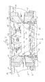
- FIG. 2 is a perspective view illustrating the rafter block mounted in a truss roof
- FIG. 3 is a sectional view of the structure of FIG. 2 taken along line 2 — 2 thereof;
- FIG. 4 is a perspective view of a typical rafter vent
- FIG. 5 is a perspective view of another typical rafter vent
- FIG. 6 is a perspective view of the rafter block of the invention oriented differently with a different rafter vent.
- FIG. 7 is a perspective view of the rafter block of the invention oriented differently with a different sized rafter vent.
- the air infiltration block 10 of FIG. 1 is shown installed in an attic space 24 of a building which has upstanding walls 12 including vertical studs 14 , a horizontal top plate 16 , joists 18 and roof rafters 20 which together form a roof 28 to which roof sheathing 30 may be secured as shown in FIGS. 2 and 3.
- the ceiling joists 18 and roof rafters 20 come together and are joined in the area of the top plate 16 .
- the roof rafters 20 extend beyond the wall 12 to form an overhang and underlying eaves 22 .
- the eaves 22 include openings 34 through which outside air is intended to flow into the attic space 24 .
- the adjacent pairs of ceiling joists 18 and roof rafters 20 , together with the roof sheathing 30 and ceiling wallboard 26 define openings 36 shown in FIGS. 2, 6 and 7 complete with a rafter air infiltration block 10 and a vent chute 40 .
- insulation which may be batting or blown-in, is on top of the ceiling wallboard 26 to at least the depth of the joists 18 .
- Proper ventilation in an attic is essential to allow removal of excess heat in summer and to deal with moisture.
- extremely cold air should not be allowed to contact any non-insulating member such as the top plate 16 or cold spots inside the house are formed.
- air flow in and out of the attic space 24 needs to be directed and controlled to prevent loss of insulation and waterlogging of the insulation due to water passing up into the eaves.
- a vent chute 40 is secured to the underside of the roof sheathing 30 as shown in FIGS. 2, 6 and 7 .
- Vent chutes 40 provide a controlled path for air flow in and out of the attic through the eaves. Since vent chutes are water resistant and angle upwardly, they prevent water from reaching the insulation. However, absent an air infiltration block 10 of the invention, water and insulation may pass under the vent chutes in and out of the eave 22 area.
- vent chutes 40 are relatively long, and as shown in FIG. 2 may be molded to define two separate channels 42 , 44 between horizontal flanges 46 , 48 and 50 which are tacked to the roof sheathing 30 with a staple gun or the like.
- the vent chute of FIG. 2 is typically 22 inches in width, illustrating how narrow the space is in which the installers must work.
- an installer should place some form of block to prevent a loss of insulation into the eaves 22 below the vent chutes 40 and to make an air infiltration seal such that air is forced away from the wall top plate 16 .
- the air infiltration block 10 of the invention is constructed of a sheet stock of stiff, waterproof material, such as a waxed paperboard.
- the waterproofing limits any damage and loss of function which would occur if simple cardboard was used.
- the block 10 is generally rectangular in shape, and includes a longitudinal fold line 58 which corresponds to a standard truss construction and a longitudinal fold line 60 which is adapted to work in roofs employing a wedge or raised heel truss.
- the block 10 is slitted or cut at regions 62 , 64 from fold lines 68 , 70 which are spaced from the ends and intersect the longitudinal fold lines 58 , 60 at right angles.
- the ends of each define three separate tabs 52 , 54 and 56 as shown in FIG. 1 .
- the area above fold line 58 on the block 10 has an outer edge that defines two channels 72 , 74 which are constructed and arranged to snugly mate with the channels 42 , 44 of a two-channel vent chute 40 as shown in FIG. 2 .
- Channels 72 , 74 are separated by an upstanding tab 78 which may be folded down along fold line 80 such that the tab 78 may be stapled through the vent chute flange 48 into the roof sheathing 30 .
- the area below fold line 60 of the block 10 has an outer edge 82 that includes a pair of tabs 84 , 86 which extend beyond the outer edge 82 at its ends and include a fold line 88 which allows the tabs to bend as desired for stapling to the top plate 16 .
- the block 10 of the invention also may include a perforation line 90 that allows all of a portion of the outer edge 82 between the tabs 84 , 86 to be removed. Removal of the sheet defined by perforation line 90 and perforation lines 92 , 94 creates a narrow, single channel 96 which mates with a vent chute 40 having only a single channel as shown in FIG. 6 . For larger single channel vent chutes as shown in FIG.
- the portion of the outer edge 82 between tabs 84 , 86 between perforation line 90 and perforation lines 100 , 102 may be removed to form a larger channel. It should be apparent that the block 10 is simply inverted 180 degrees such that channel 96 is placed up toward the vent chutes 40 when a single channel vent chute 40 is to be used. Thus, a single block 10 of the invention may be quickly adapted in the field to work with either a single or double channel vent chute 40 without requiring any tools.
- a block 10 is used as is, and the installers simply bends the block at fold line 60 , bends in each of the tabs 52 , 54 and 56 to a right angle and inserts the block tightly up against the vent chute 40 such that the vent chute channels 42 , 44 mate with the channels 72 , 74 of the block 10 .
- Tab 78 is bent forward and attached to the roof sheathing 30 by a staple or the like.
- each of tabs 52 , 54 and 56 may be tacked or stapled to the joists 18 and rafters 20 as shown.
- tabs 84 may be secured to the top plate 16 . Together, the block forms a tight water resistant seal exactly where needed to prevent insulation loss, moisture wicking into the insulation and to prevent cold spots due to air infiltration where it is not desired.
- the block 10 is simply inverted, and channel 96 is formed by removing the sheet defined by lines 90 , 92 and 94 .
- the tabs are then folded as before and the block is slid into a tight sealing engagement with the vent chute 40 .
- a stapler or tacker may then secure the block in place at several or all of the tabs, depending on the ease of reaching each tab.
- the block 10 is inverted as above, but the channel 96 is made larger by removing the sheet defined by lines 90 , 100 and 102 to fit the larger sized vent chute.
- the block 10 is then secured as previously described. Note that all examples show a truss system of double height. A single height truss design would simply involve using fold line 58 as the interfacing line abutting against the top plate 16 instead of fold line 60 as shown.
- the single air infiltration block of the invention is usable in double and single-height roof trusses, will work with different vent chute sizes and configurations and is water resistant to prevent loss of integrity when rain water reaches it up through the eaves 22 . It may be installed without a need for a scissors and simply requires inversion or a removal of excess sheet stock at the perforation lines.
Abstract
Description
Claims (8)
Priority Applications (1)
| Application Number | Priority Date | Filing Date | Title |
|---|---|---|---|
| US09/721,274 US6357185B1 (en) | 1999-12-06 | 2000-11-22 | Rafter air infiltration block |
Applications Claiming Priority (2)
| Application Number | Priority Date | Filing Date | Title |
|---|---|---|---|
| US16933199P | 1999-12-06 | 1999-12-06 | |
| US09/721,274 US6357185B1 (en) | 1999-12-06 | 2000-11-22 | Rafter air infiltration block |
Publications (1)
| Publication Number | Publication Date |
|---|---|
| US6357185B1 true US6357185B1 (en) | 2002-03-19 |
Family
ID=26864966
Family Applications (1)
| Application Number | Title | Priority Date | Filing Date |
|---|---|---|---|
| US09/721,274 Expired - Fee Related US6357185B1 (en) | 1999-12-06 | 2000-11-22 | Rafter air infiltration block |
Country Status (1)
| Country | Link |
|---|---|
| US (1) | US6357185B1 (en) |
Cited By (26)
| Publication number | Priority date | Publication date | Assignee | Title |
|---|---|---|---|---|
| US20020069607A1 (en) * | 1994-02-02 | 2002-06-13 | Thompson Thomas C. | Retrofit hurricane and earthquake protection |
| US6780099B1 (en) | 2003-04-28 | 2004-08-24 | Richard W. Harper | Roof ventilation system |
| US20050072072A1 (en) * | 2003-09-19 | 2005-04-07 | Cerainteed Corporation | Baffled attic vent including method of making and using same |
| US20050215192A1 (en) * | 2004-03-29 | 2005-09-29 | Brentwood Industries, Inc. | Vent baffle and method of installation |
| US20060117686A1 (en) * | 2004-11-23 | 2006-06-08 | Mankell Kurt O | Insulation batt having integral baffle vent |
| US20060123724A1 (en) * | 2004-12-09 | 2006-06-15 | Pollack Robert W | Device and method to provide air circulation space proximate to insulation material |
| US20070094966A1 (en) * | 2004-11-23 | 2007-05-03 | Certainteed Corporation | Insulation Batt Having Integral Baffle Vent |
| US20070151176A1 (en) * | 2005-12-31 | 2007-07-05 | Mumaw John R | Hinged roof vent for attic |
| US20070283639A1 (en) * | 2006-06-12 | 2007-12-13 | Matt Kortuem | Cathedral ceiling vent baffle and method of installation |
| US20080163565A1 (en) * | 2007-01-04 | 2008-07-10 | Murray Toas | Insulation batt with integral air vent |
| US20080216419A1 (en) * | 2007-03-06 | 2008-09-11 | Brentwood Industries, Inc. | Insulation Block and Baffle Vent for Manufactured Housing |
| US20080280554A1 (en) * | 2004-03-29 | 2008-11-13 | Brentwood Industries, Inc. | Adjustable Width Vent Baffle |
| US20090044797A1 (en) * | 2007-08-13 | 2009-02-19 | Michael Robert Klement | Radiant baffle/collector for roof construction and retrofit |
| US20100263301A1 (en) * | 2006-09-11 | 2010-10-21 | Mr. Ronald E. Prass, JR. | Energy-saving baffle |
| US20110088334A1 (en) * | 2009-10-19 | 2011-04-21 | E. I. Du Pont De Nemours And Company | Article and method for controlling moisture |
| US7941987B1 (en) * | 2009-01-26 | 2011-05-17 | Raim Michael E | Tile spacer and method for its use |
| US20110277405A1 (en) * | 2010-05-14 | 2011-11-17 | Features Walter | Modular building panel and duct system |
| US8590229B2 (en) | 2010-09-15 | 2013-11-26 | Shurtech Brands, Llc | Inflatable attic stairway insulation appliance |
| US20140115980A1 (en) * | 2012-11-01 | 2014-05-01 | 3M Innovative Properties Company | Above-deck roof venting article |
| US8763330B2 (en) | 2004-12-09 | 2014-07-01 | Robert W. Pollack | Devices and methods to provide air circulation space proximate to insulation material |
| EP2789757A1 (en) * | 2013-04-12 | 2014-10-15 | Enviroform Solutions Limited | Insulation assembly for floor joists |
| US20140311070A1 (en) * | 2004-12-09 | 2014-10-23 | Robert W. Pollack | Devices and methods to provide air circulation space proximate to insulation material |
| US20160116176A1 (en) * | 2011-12-22 | 2016-04-28 | 3M Innovative Properties Company | Above-deck roof venting article |
| US20170067246A1 (en) * | 2015-09-09 | 2017-03-09 | Glen R. HUDSON | Vapour Barrier Pan |
| US10094119B2 (en) * | 2016-04-19 | 2018-10-09 | Jonas MORELLI | Roof rafter thermal break system |
| US10697182B2 (en) | 2018-01-10 | 2020-06-30 | Barry R. Huber | Rafter vent system for hip roofs and valleys |
Citations (17)
| Publication number | Priority date | Publication date | Assignee | Title |
|---|---|---|---|---|
| US3863553A (en) * | 1973-12-20 | 1975-02-04 | Bryce L Koontz | Combination insulation stop and ventilation baffle |
| US4102092A (en) * | 1977-04-15 | 1978-07-25 | Ward Bruce K | Venting device |
| US4125982A (en) * | 1977-09-19 | 1978-11-21 | Ward Bruce K | Floor joist insulation baffle |
| US4125971A (en) * | 1977-09-19 | 1978-11-21 | Diversified Insulation, Inc. | Vent and baffle |
| US4151894A (en) | 1977-10-17 | 1979-05-01 | Edwards Robert A | Insulating cover for pull down stair |
| US4185433A (en) | 1978-05-22 | 1980-01-29 | Thermal Insulation Company | Baffle board construction |
| US4189878A (en) * | 1977-04-15 | 1980-02-26 | Fitzgerald Gerald A | House roof insulation vent |
| US4197683A (en) * | 1977-09-19 | 1980-04-15 | Diversified Insulation, Inc. | Vent and baffles |
| US4214510A (en) * | 1978-09-14 | 1980-07-29 | Ward Bruce K | Vent and baffle unit |
| US4502368A (en) | 1983-08-15 | 1985-03-05 | Hempel George T | Air vent cover |
| US4567074A (en) | 1985-03-21 | 1986-01-28 | Litaker Stephen H | Insulating trap door cover |
| US4581861A (en) | 1984-04-27 | 1986-04-15 | Eury Matthew D | Baffle board construction |
| US4611443A (en) * | 1984-01-13 | 1986-09-16 | Jorgensen Ralph H | Wall line insulation pillows |
| US4658555A (en) | 1985-07-12 | 1987-04-21 | Steiner Thomas J | Attic hatchway insulating cover |
| US5007216A (en) * | 1989-07-18 | 1991-04-16 | Pearson David H | Ventilation baffle and insulation stop |
| US5341612A (en) * | 1992-07-16 | 1994-08-30 | Inno-Tech Plastics, Inc. | Baffle vent structure |
| US6112490A (en) * | 1997-03-06 | 2000-09-05 | Meyer; Donald L. | Spray insulation shield apparatus and application method |
-
2000
- 2000-11-22 US US09/721,274 patent/US6357185B1/en not_active Expired - Fee Related
Patent Citations (17)
| Publication number | Priority date | Publication date | Assignee | Title |
|---|---|---|---|---|
| US3863553A (en) * | 1973-12-20 | 1975-02-04 | Bryce L Koontz | Combination insulation stop and ventilation baffle |
| US4102092A (en) * | 1977-04-15 | 1978-07-25 | Ward Bruce K | Venting device |
| US4189878A (en) * | 1977-04-15 | 1980-02-26 | Fitzgerald Gerald A | House roof insulation vent |
| US4125982A (en) * | 1977-09-19 | 1978-11-21 | Ward Bruce K | Floor joist insulation baffle |
| US4125971A (en) * | 1977-09-19 | 1978-11-21 | Diversified Insulation, Inc. | Vent and baffle |
| US4197683A (en) * | 1977-09-19 | 1980-04-15 | Diversified Insulation, Inc. | Vent and baffles |
| US4151894A (en) | 1977-10-17 | 1979-05-01 | Edwards Robert A | Insulating cover for pull down stair |
| US4185433A (en) | 1978-05-22 | 1980-01-29 | Thermal Insulation Company | Baffle board construction |
| US4214510A (en) * | 1978-09-14 | 1980-07-29 | Ward Bruce K | Vent and baffle unit |
| US4502368A (en) | 1983-08-15 | 1985-03-05 | Hempel George T | Air vent cover |
| US4611443A (en) * | 1984-01-13 | 1986-09-16 | Jorgensen Ralph H | Wall line insulation pillows |
| US4581861A (en) | 1984-04-27 | 1986-04-15 | Eury Matthew D | Baffle board construction |
| US4567074A (en) | 1985-03-21 | 1986-01-28 | Litaker Stephen H | Insulating trap door cover |
| US4658555A (en) | 1985-07-12 | 1987-04-21 | Steiner Thomas J | Attic hatchway insulating cover |
| US5007216A (en) * | 1989-07-18 | 1991-04-16 | Pearson David H | Ventilation baffle and insulation stop |
| US5341612A (en) * | 1992-07-16 | 1994-08-30 | Inno-Tech Plastics, Inc. | Baffle vent structure |
| US6112490A (en) * | 1997-03-06 | 2000-09-05 | Meyer; Donald L. | Spray insulation shield apparatus and application method |
Cited By (47)
| Publication number | Priority date | Publication date | Assignee | Title |
|---|---|---|---|---|
| US7134252B2 (en) * | 1994-02-02 | 2006-11-14 | Thompson Thomas C | Retrofit hurricane and earthquake protection |
| US20020069607A1 (en) * | 1994-02-02 | 2002-06-13 | Thompson Thomas C. | Retrofit hurricane and earthquake protection |
| US6780099B1 (en) | 2003-04-28 | 2004-08-24 | Richard W. Harper | Roof ventilation system |
| US20050160684A1 (en) * | 2003-09-19 | 2005-07-28 | Duncan Richard S. | Reconfigurable attic air vent |
| US7302776B2 (en) | 2003-09-19 | 2007-12-04 | Certainteed Corporation | Baffled attic vent |
| US7765750B2 (en) | 2003-09-19 | 2010-08-03 | Certainteed Corporation | Reconfigurable attic air vent |
| US20050072072A1 (en) * | 2003-09-19 | 2005-04-07 | Cerainteed Corporation | Baffled attic vent including method of making and using same |
| US20050215192A1 (en) * | 2004-03-29 | 2005-09-29 | Brentwood Industries, Inc. | Vent baffle and method of installation |
| US20060105699A1 (en) * | 2004-03-29 | 2006-05-18 | Brentwood Industries, Inc. | Vent baffle and perforation machine |
| US8647184B2 (en) * | 2004-03-29 | 2014-02-11 | Brentwood Industries, Inc. | Adjustable width vent baffle |
| US8079293B2 (en) | 2004-03-29 | 2011-12-20 | Brentwood Industries, Inc. | Perforation machine for manufacturing adjustable vent baffles |
| US7094145B2 (en) * | 2004-03-29 | 2006-08-22 | Brentwood Industries, Inc. | Vent baffle and method of installation |
| US20080280554A1 (en) * | 2004-03-29 | 2008-11-13 | Brentwood Industries, Inc. | Adjustable Width Vent Baffle |
| US20080041212A1 (en) * | 2004-03-29 | 2008-02-21 | Matt Kortuem | Perforation machine for manufacturing adjustable vent baffles |
| US7644545B2 (en) | 2004-11-23 | 2010-01-12 | Certainteed Corporation | Insulation batt having integral baffle vent |
| US20070094966A1 (en) * | 2004-11-23 | 2007-05-03 | Certainteed Corporation | Insulation Batt Having Integral Baffle Vent |
| US20060117686A1 (en) * | 2004-11-23 | 2006-06-08 | Mankell Kurt O | Insulation batt having integral baffle vent |
| US7921619B2 (en) | 2004-11-23 | 2011-04-12 | Certainteed Corporation | Insulation batt having integral baffle vent |
| US8763330B2 (en) | 2004-12-09 | 2014-07-01 | Robert W. Pollack | Devices and methods to provide air circulation space proximate to insulation material |
| US20060123724A1 (en) * | 2004-12-09 | 2006-06-15 | Pollack Robert W | Device and method to provide air circulation space proximate to insulation material |
| US20140311070A1 (en) * | 2004-12-09 | 2014-10-23 | Robert W. Pollack | Devices and methods to provide air circulation space proximate to insulation material |
| US7458189B2 (en) | 2004-12-09 | 2008-12-02 | Pollack Robert W | Device and method to provide air circulation space proximate to insulation material |
| WO2007021298A3 (en) * | 2005-08-12 | 2007-11-08 | Robert W Pollack | Device and method to provide air circulation space proximate to insulation material |
| WO2007021298A2 (en) * | 2005-08-12 | 2007-02-22 | Pollack Robert W | Device and method to provide air circulation space proximate to insulation material |
| US20070151176A1 (en) * | 2005-12-31 | 2007-07-05 | Mumaw John R | Hinged roof vent for attic |
| US20070283639A1 (en) * | 2006-06-12 | 2007-12-13 | Matt Kortuem | Cathedral ceiling vent baffle and method of installation |
| US7856764B2 (en) * | 2006-06-12 | 2010-12-28 | Brentwood Industries, Inc. | Cathedral ceiling vent baffle |
| US20100263301A1 (en) * | 2006-09-11 | 2010-10-21 | Mr. Ronald E. Prass, JR. | Energy-saving baffle |
| US20080163565A1 (en) * | 2007-01-04 | 2008-07-10 | Murray Toas | Insulation batt with integral air vent |
| US20080216419A1 (en) * | 2007-03-06 | 2008-09-11 | Brentwood Industries, Inc. | Insulation Block and Baffle Vent for Manufactured Housing |
| US7841137B2 (en) | 2007-03-06 | 2010-11-30 | Brentwood Industries, Inc. | Insulation block and baffle vent for manufactured housing |
| US20090044797A1 (en) * | 2007-08-13 | 2009-02-19 | Michael Robert Klement | Radiant baffle/collector for roof construction and retrofit |
| US8562400B2 (en) | 2007-08-13 | 2013-10-22 | Michael Robert Klement | Radiant baffle/collector for roof construction and retrofit |
| US8137170B2 (en) | 2007-08-13 | 2012-03-20 | Michael Robert Klement | Radiant baffle/collector for roof construction and retrofit |
| US7941987B1 (en) * | 2009-01-26 | 2011-05-17 | Raim Michael E | Tile spacer and method for its use |
| US20110088334A1 (en) * | 2009-10-19 | 2011-04-21 | E. I. Du Pont De Nemours And Company | Article and method for controlling moisture |
| US20120204507A1 (en) * | 2009-10-19 | 2012-08-16 | E.I. Du Pont De Nemours And Company | Article and method for controlling moisture |
| US8756888B2 (en) * | 2010-05-14 | 2014-06-24 | Feature Walters | Modular building panel and duct system |
| US20110277405A1 (en) * | 2010-05-14 | 2011-11-17 | Features Walter | Modular building panel and duct system |
| US8590229B2 (en) | 2010-09-15 | 2013-11-26 | Shurtech Brands, Llc | Inflatable attic stairway insulation appliance |
| US20160116176A1 (en) * | 2011-12-22 | 2016-04-28 | 3M Innovative Properties Company | Above-deck roof venting article |
| US20140115980A1 (en) * | 2012-11-01 | 2014-05-01 | 3M Innovative Properties Company | Above-deck roof venting article |
| US9228355B2 (en) * | 2012-11-01 | 2016-01-05 | 3M Innovative Properties Company | Above-deck roof venting article |
| EP2789757A1 (en) * | 2013-04-12 | 2014-10-15 | Enviroform Solutions Limited | Insulation assembly for floor joists |
| US20170067246A1 (en) * | 2015-09-09 | 2017-03-09 | Glen R. HUDSON | Vapour Barrier Pan |
| US10094119B2 (en) * | 2016-04-19 | 2018-10-09 | Jonas MORELLI | Roof rafter thermal break system |
| US10697182B2 (en) | 2018-01-10 | 2020-06-30 | Barry R. Huber | Rafter vent system for hip roofs and valleys |
Similar Documents
| Publication | Publication Date | Title |
|---|---|---|
| US6357185B1 (en) | Rafter air infiltration block | |
| US4189878A (en) | House roof insulation vent | |
| US4214510A (en) | Vent and baffle unit | |
| US7765750B2 (en) | Reconfigurable attic air vent | |
| US4581861A (en) | Baffle board construction | |
| US4643080A (en) | Roof ridge ventilator system | |
| US3863553A (en) | Combination insulation stop and ventilation baffle | |
| US4096790A (en) | Ventilation and insulation baffle | |
| US5596847A (en) | Baffle vent structure | |
| US3972164A (en) | Roof construction with inlet and outlet venting means | |
| US5740636A (en) | Weather block and vent | |
| US3797180A (en) | Ventilated roof construction | |
| US6346040B1 (en) | Soffit to attic vent | |
| EP0026178B1 (en) | A spacer means for providing air gaps between a roof or ceiling and its insulation | |
| US5832677A (en) | Eve air vent | |
| US4607566A (en) | Ventilator for use in a roof structure | |
| US4185433A (en) | Baffle board construction | |
| CA2359172C (en) | Hinged vent chute | |
| US20070151177A1 (en) | Hinged roof vent for attic | |
| US5361551A (en) | Ventilation spacer for roof construction | |
| US4223489A (en) | Insulation stop | |
| US8647184B2 (en) | Adjustable width vent baffle | |
| US5950375A (en) | Combined fascia and soffit member roll-formed from sheet metal | |
| US20070151176A1 (en) | Hinged roof vent for attic | |
| US4972635A (en) | Cant vent and rim guard air and moisture stops |
Legal Events
| Date | Code | Title | Description |
|---|---|---|---|
| AS | Assignment |
Owner name: ADO, INC., MINNESOTA Free format text: ASSIGNMENT OF ASSIGNORS INTEREST;ASSIGNORS:OBERMEYER, KEITH G.;ANDREWS, JAMES S.;KOCH, DAVID WAYNE;AND OTHERS;REEL/FRAME:011329/0041;SIGNING DATES FROM 20001103 TO 20001106 |
|
| FPAY | Fee payment |
Year of fee payment: 4 |
|
| AS | Assignment |
Owner name: ADO PRODUCTS, LLC, MINNESOTA Free format text: MERGER;ASSIGNOR:ADO, INC.;REEL/FRAME:021691/0052 Effective date: 20080831 |
|
| FPAY | Fee payment |
Year of fee payment: 8 |
|
| REMI | Maintenance fee reminder mailed | ||
| LAPS | Lapse for failure to pay maintenance fees | ||
| STCH | Information on status: patent discontinuation |
Free format text: PATENT EXPIRED DUE TO NONPAYMENT OF MAINTENANCE FEES UNDER 37 CFR 1.362 |
|
| FP | Lapsed due to failure to pay maintenance fee |
Effective date: 20140319 |