US6356082B1 - Utility locator radio link - Google Patents
Utility locator radio link Download PDFInfo
- Publication number
- US6356082B1 US6356082B1 US09/579,711 US57971100A US6356082B1 US 6356082 B1 US6356082 B1 US 6356082B1 US 57971100 A US57971100 A US 57971100A US 6356082 B1 US6356082 B1 US 6356082B1
- Authority
- US
- United States
- Prior art keywords
- locator
- transmitter
- receiver
- magnetic
- radio link
- Prior art date
- Legal status (The legal status is an assumption and is not a legal conclusion. Google has not performed a legal analysis and makes no representation as to the accuracy of the status listed.)
- Expired - Lifetime
Links
Images


Classifications
-
- G—PHYSICS
- G01—MEASURING; TESTING
- G01V—GEOPHYSICS; GRAVITATIONAL MEASUREMENTS; DETECTING MASSES OR OBJECTS; TAGS
- G01V3/00—Electric or magnetic prospecting or detecting; Measuring magnetic field characteristics of the earth, e.g. declination, deviation
- G01V3/02—Electric or magnetic prospecting or detecting; Measuring magnetic field characteristics of the earth, e.g. declination, deviation operating with propagation of electric current
- G01V3/06—Electric or magnetic prospecting or detecting; Measuring magnetic field characteristics of the earth, e.g. declination, deviation operating with propagation of electric current using ac
Definitions
- This invention relates to instruments for locating and following underground pipes, cables, and other underground entities which have electrical continuity, whether inherent naturally therein or intentionally associated therewith.
- Non-conductive underground utilities such as fiber optic cables, are commonly provided along their entire length with either an electrically conductive sheath or an electrically conductive lead intimately associated therewith. See Mercer, U.S. Pat. No. 5,914,602, incorporated herein by reference.
- a common technique is to hook a transmitter to an access point on the utility being traced, such as a water meter, electrical switch box, etc., and to apply thereto an electrical signal of a known alternating current frequency. The utility responds by radiating a magnetic field of the same frequency along its entire length.
- An operater attempts to follow the path of the underground portion of the utility by detecting the magnetic field with a receiver tuned to the radiated signal.
- the radiated frequency can be detected to the exclusion of other signals, and the underground portion of the utility can be faithfully traced.
- Applicants' invention overcomes these problems by providing a radio link between the receiver and the transmitter which permits the operator to send commands from the receiver to the transmitter which controls selected transmitter functions and which provides the operator with critical information concerning conditions at the transmitter.
- the combination permits the operator to remain remote from the transmitter while detecting and/or correcting many common problems.
- Yokoi U.S. Pat. No. 5,194,812 interconnects transmitter and receiver with a radio link, but the RF signal is only a reference frequency to reduce the effects of noise, not a communication link for interrogating and/or controlling the transmitter.
- Yokoi teaches selecting a detector frequency appropriate for the type of utility to be traced, but does not teach changing that frequency once it has been selected due to events arising during field operations. Yokoi especially does not teach changing the tranmission frequency from the receiver.
- Rider, U.S. Pat. No. 5,264,795 establishes communications between an operator at the transmitter and an operator at the receiver by means of a modulated signal induced in the pipe.
- the use of the induction signal as the communications carrier is inherently less efficient and less reliable than the use of a radio link.
- Rider teaches communications between people, one at the transmitter and one at the receiver, not between receiver and transmitter per se. Rider continuously sends battery level information from transmitter to receiver without operator intervention, but he does not teach sending battery level information only upon request from a remote operator.
- Archambeault et al. U.S. Pat. No. 5,469,155, and Mercer, U.S. Pat. No. 5,698,981, relay drill head signals picked up by a receiver to the operator at the drill control panel.
- Archambeault et al. use the information to control the drill; Mercer uses the information to record the drill path.
- Mercer, U.S. Pat. No. 5,914,602, supra radios signals from pipes or drill heads directly to the drill operator. All require an operator at the transmitter, and none teach controlling tranmitter functions by an operator remotely located with the receiver.
- a radio link is established between the portable receiver used by an operator to trace the underground portion of a utility and the transmitter which induces a magnetic signal in the utility.
- Circuitry in both transmitter and receiver allows the operator to interrogate the transmitter for essential information, such as whether or not the transmitter is generating a signal, the frequency being used in the transmission, the level of the transmitter's battery, or whether or not a complete transmission circuit is existent.
- Circuitry is also provided for controlling functions at the transmitter from the receiver carried by an operator remote from the transmitter, such as changing the transmission frequency of the generator, or conserving battery power by switching the transmitter's frequency generator off during periods of non-use.
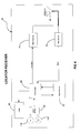
- FIG. 1 is a diagrammatic representation which illustrates a preferred embodiment of the present invention depicting its use in the field;
- FIG. 2 is a block diagram of the magnetic transmitter
- FIG. 3 is a block diagram of the magnetic receiver detecting a magnetic field
- FIG. 4 is a block diagram of the locator receiver
- FIG. 5 is a block diagram of the locator transmitter
- FIG. 6 is a block diagram of the radio transmitters
- FIG. 7 is a block diagram of the radio receivers
- FIG. 8 is a top pictorial view of a portion of the control panel of the locator receiver.
- FIG. 9 is a flow chart showing one type of operation of the locator transmitter microprocessor.
- the general activity of the invention is the locating and tracing of an electrically conductive underground utility.
- the specific activity of the invention is to establish a radio link capable of interrogating and/or controlling the transmitter from the receiver in order to facilitate the locating and tracing functions by a single operator.
- An underground utility 10 is shown for illustrative purposes as a water pipe, although electrical cables, e.g., power cables or CATV cables, and other non-electrical lines, e.g., a plastic gas line or an optical cable, which have associated therewith a conductive strip or sheath, are also traceable subjects.
- Pipe 10 has an underground portion 12 and an aboveground portion 14 which surfaces above ground level 16 where it is connected to a utility source or to a user facility such as a water meter (not shown).
- a locator transmitter 18 is connected by a “positive” electrical cable 20 to aboveground portion 14 of pipe 10 and connected by a “negative” ground cable 22 to a metal stake 24 driven into the ground.
- the natural conductivity of the earth closes an electrically conductive ground return path 26 between pipe 10 and stake 24 , a prerequisite for the transmission of signals along pipe 10 .
- Locator transmitter 18 induces an AC electrical signal of a preselected frequency into pipe 10 . Because it is conductive, pipe 10 responds to the imposition of an alternating current electrical signal by generating a distinctive magnetic field of the same frequency around pipe 10 all along its conductive length. In FIG.
- Locator receiver 30 is carried by an operator 32 along surface 16 above pipe 10 . Locator receiver 30 is tuned to the frequency of magnetic field 28 and, based on the detected strength of field 28 , gives an indication of the location of pipe 10 , thus allowing operator 32 to follow the path of its underground portion 12 .
- Locator transmitter 18 includes a magnetic transmitter 34 (FIG. 2) comprising a programmable frequency generator 36 , a first bank of relays 38 , a plurality of resonant LC circuits 40 , and a second bank of relays 42 .
- magnetic transmitter 34 receives a frequency select signal 44 which directs frequency generator 36 to select a 20 particular frequency fi from a plurality of available frequencies f 1 , f 2 , f 3 , f 4 . . . fn.
- the selected frequency fi is supplied to said first bank of relays 38 .
- magnetic transmitter 34 receives a relay control signal 46 which simultaneously connects both of said first and second banks of relays 38 and 42 to the input and output, respectively, of the particular resonant LC circuit 40 which is tuned to said selected frequency fi.
- Resonant LC circuit 40 tunes the circuit and provides the high current drive needed from magnetic transmitter 34 in order for output current 48 to be sufficient to induce a strong magnetic signal around pipe 10 .
- Locator receiver 30 includes a magnetic receiver 50 (FIG. 3) comprising an array of magnetic sensors 52 , a band pass preamplifier 54 , a sensor select 56 , a band pass filter 58 , an analog-to-digital converter 60 , and a control and processor interface 62 .
- Magnetic sensors 52 detect the horizontal component and/or the vertical component of magnetic field 28 , depending on the operating mode selected by operator 32 .
- Array 52 thus provides a plurality of signals (one from each sensor) which, when mathematically combined, has values indicative of the location (direction and/or distance) of pipe 10 from locator receiver 30 .
- the array of magnetic sensors 52 it is within the scope of the invention for the array of magnetic sensors 52 to include as many sensors as is necessary for the job being contemplated. See the U.S. Pat. No. 4,091,322, to Stankoff, Tavernetti et al., U.S. Pat. No. 5,043,666, and Balkman, U.S. Pat. No. 5,093,622, all incorporated herein by reference, for a non-exhaustive collection of samples of magnetic sensor arrays which would be suitable for use in the invention.
- the plurality of signals from array 52 are fed to band pass preamplifier 54 which eliminates unwanted noise, amplifies the signals derived from magnetic sensors 52 , and passes them on to sensor select 56 .
- Sensor select 56 is a multiplexer controlled by the microprocessor 64 in locator receiver 30 (FIG. 4) which selects one of the magnetic sensor signals for input into band pass filter 58 .
- BP filter 58 further removes unwanted noise and amplifies the desired signal to a level adequate to drive the input of A/D converter 60 . From this point on, the signals must be in digital form so that they are suitable for subsequent manipulation by microprocessor 64 . Consequently, all signals from band pass filter 58 are converted to digital signals by analog-to-digital converter 60 prior to being received by microprocessor 64 .
- Control and processor interface 62 under the control of microprocessor 64 , sets the gain of preamplifier 54 , instructs sensor select 56 as to which sensor's signals to select, sets the gain and adjusts the bandwidth of band pass filter 58 , and sets up the timing and handshaking signals for the A/D converter 60 .
- locator receiver 30 pertinent components of locator receiver 30 are shown in block form.
- the output signals from magnetic receiver 50 are processed by microprocessor 64 and the results (direction, distance, etc., of pipe 10 ) are displayed as a location indication (not shown) on a suitable display 66 (FIGS. 4 and 8 ).
- operator 32 attaches cables 20 and 22 to the aboveground portion 14 of pipe 10 and stake 24 , respectively, turns on both locator transmitter 18 and locator receiver 30 , selects a frequency appropriate to the utility in question, and marches off with locator receiver 30 to trace the underground portion 12 of pipe 10 .
- operator 32 is faced with a quandary: Is the cause of the cessation of the location indication due to equipment failure or is the cause due to a change in conditions independent of the operating system? Has pipe 10 ceased radiating magnetic signals? If so, why are there no signals? Are electrical signals still being induced in pipe 10 ? If not, why? Is locator transmitter 18 still on? Has its battery failed?
- locator transmitter 18 Has locator transmitter 18 been destroyed or stolen? Has the electrical connection between locator transmitter 18 and pipe 10 been broken, e.g., has cable 20 and/or cable 22 come loose? If the equipment is operating properly, and operator 32 has no right to assume it is, is the problem due to causes other than equipment failure? Is pipe 10 passing through a region which is introducing magnetic fields from sources other than magnetic transmitter 34 such that the noise created thereby could be interfering with magnetic field 28 , in effect, masking it? (If so, changing programmable frequency generator 36 to a different frequency will often result in a detectable signal.) Has the underground portion 12 of pipe 10 taken a sudden dip or turn?
- the dilemma is resolved by establishing a two-way radio link 72 (FIG. 1) between locator transmitter 18 and locator receiver 30 , and circuitry is provided in both to permit operator 32 to interrogate locator transmitter 18 and to control certain functions produced thereby from locator receiver 30 .
- locator receiver 30 further includes a radio transmitter 74 and a radio receiver 76 , both of which are operatively connected to an antenna 78 .
- locator transmitter 18 includes a radio transmitter 80 and a radio receiver 82 which are operatively connected to an antenna 84 . Since radio transmitters 74 and 80 are identical, and since radio receivers 76 and 82 are also identical, only one of each needs to be described. It is to be understood that any suitable transmitter and/or receiver can be utilized within the scope of the invention, but the presently preferred best mode is as shown in FIGS. 6 and 7.
- radio transmitters 74 and 80 are described.
- the carrier frequency of the transmitter employed is derived by a synthesizer 85 comprising a local oscillator 86 , a phase detector 88 , a Voltage Controlled Oscillator 90 , a divider 92 , and a filter 94 .
- synthesizer 85 offers the advantages of accuracy, small physical size, and no adjustable components.
- Local oscillator 86 is a crystal oscillator which produces a stable reference frequency.
- Phase detector 88 compares this frequency with the output of the Voltage Controlled Oscillator 90 after its frequency is divided by a fixed modulus by divider 92 .
- the output of phase detector 88 is filtered by filter 94 and is applied to the input of VCO 90 to complete a phase lock loop.
- the VCO output frequency which is also the transmit carrier frequency, will be equal to the reference frequency multiplied by the divide modulus.
- Data 96 to be transmitted is summed in adder 98 with the output of filter 94 and the sum is injected into VCO 90 . Injection of the summed data will momentarily drive the VCO output frequency to another value, effecting frequency modulation of the carrier. In time, the phase lock loop will correct the VCO output frequency back to its original value.
- Frequency Shift Keying This consists of shifting the frequency of the carrier between two values as dictated by the binary input data stream, i.e., transmit data 96 . A zero shifts the carrier frequency in one direction; a one shifts the carrier frequency in the opposite direction.
- effective communication requires that the transmit data rate be at least an order of magnitude greater than the phase lock loop bandwidth and the transmit data 96 must be encoded so that its average value is zero.
- the modulated frequency signals are amplified by radio frequency amplifier 100 for transmission from its associated antenna 78 or 84 .
- the transmitted data 96 is received by the other antenna 84 or 78 (FIG. 7) where it is immediately amplified by RF amplifier 102 .
- the amplified signal is combined by mixer 104 with the fixed frequency from local oscillator 106 to extract the modulated data from the carrier frequency.
- the extracted data signal is filtered by discriminator 110 and digitized by voltage comparator 112 .
- the digital signal is then forwarded to the associated microprocessor.
- Housing 114 (FIG. 8) of locator receiver 30 includes a pair of control buttons, an MT (Magnetic Transmitter) on/off button 116 and a frequency select button 118 , both of which access microprocessor 64 through a switch interface 120 (FIG. 4 ).
- Control buttons 116 and 118 comprise a pair of operator manipulated controls, each of which initiates a control signal for controlling a specified operating function of locator transmitter 18 . Alternate depressions of MT on/off button 116 turn magnetic transmitter 34 on and off.
- frequency select button 118 Scroll through the set of permissible frequencies f 1 , f 2 , f 3 , f 4 . . . fn that programmable frequency generator 36 is designed to generate. Selection of frequency fi is made by stopping the scrolling operation. Buttons 116 and 118 are mounted in facing relationship with operator 32 adjacent display 66 . Display 66 is an LCD panel which is capable of displaying text or graphics to operator 32 . As shown in FIG.
- display 66 provides operator 32 with at least the following information: (1) the frequency fi (8 kHz), presently being imposed upon pipe 10 ; (2) the status (Low) of battery 122 ; (3) the on/off state (ON) of magnetic transmitter 34 ; and (4) the status (Good) of the magnetic circuit comprising cable 20 , pipe 10 , ground return path 26 , stake 24 , and cable 22 .
- operator 32 starts the tracing activity by turning on locator transmitter 18 and locator receiver 30 by switches which are not shown.
- MT on/off 116 is depressed to turn on magnetic transmitter 34 , and a frequency fi for generation by programmable frequency generator 36 is selected by operation of frequency select button 118 .
- Microprocessor 64 senses the inputs from buttons 116 and 118 and sends the appropriate related commands to radio transmitter 74 which in turn broadcasts them from antenna 78 .
- Antenna 84 and radio receiver 82 of locator transmitter 18 receive the commands and supplies them to microprocessor 124 of locator transmitter 18 .
- microprocessor 124 turns on magnetic transmitter 34 and, by means of the appropriate frequency select signal 44 , commands the programmable frequency generator 36 of magnetic transmitter 34 (FIG. 2) to generate the requested frequency. Concurrently, microprocessor 124 sends a relay control signal 46 to the first and second banks of relays 38 and 42 to select the LC resonant circuit 40 consonant with the selected frequency. The on/off status of magnetic transmitter 34 plus a readout of the selected frequency are sent back to locator receiver 30 by radio transmitter 80 and antenna 84 under the direction of microprocessor 124 . Operator 32 is now ready to commence tracing pipe 10 .
- magnetic transmitter 34 may be turned off by depression of MT on/off button 116 . This allows operator 32 to conserve the power remaining in battery 122 (FIG. 5) in locator transmitter 18 during periods of non-use.
- battery 122 FIG. 5
- One of the major annoyances while tracing an underground utility is to have it interrupted or terminated by battery failure.
- the disclosed invention greatly extends the life of battery 122 by being capable of selectively turning off magnetic transmitter 34 from locator receiver 30 .
- VLF signals are constantly being broadcast, such as, for example, on the East Coast of the United States by the U.S. Navy at frequencies of 17.8 KHz and 21.4 KHz. Buried metallic objects or metallic ores respond by radiating magnetic fields. Others in the art have made use of these signals to trace underground utilities. The frequencies of these unwanted magnetic fields often interfere with the frequency fi imposed on pipe 10 by magnetic transmitter 34 . When this occurs, the usual practice is for the operator to return to locator transmitter 18 , change the transmitted frequency, and retrace pipe 10 as many times as is necessary to find a frequency which is outside the bandwidth of the unwanted, interfering frequencies.
- the operator can tune the locator receiver 30 to detect only the desired frequency, but as pointed out before, these systems tax the battery and make if more difficult to accurately detect the desired frequency.
- operator 32 can correct the problem by simply scrolling through frequencies f 1 , f 2 , f 3 , f 4 . . . fn until a readable signal is again detected by magnetic receiver 50 , accomplishing the feat without having once to return to home base to change frequencies on locator transmitter 18 .
- Microprocessor 64 processes the new entry and actuates radio transmitter 74 to send the instructions to locator transmitter 18 .
- Locator transmitter 18 responds by changing fi in the manner described above and notifies locator receiver 30 of the new frequency which is displayed on LCD screen 66 .
- the remaining status indications on display screen 66 namely, the battery status and the status of the circuit connection, are constantly being monitored by circuitry within locator transmitter 18 .
- Analog-to-digital converter 126 (FIG. 5) monitors the voltage level of battery 122 and supplies the battery voltage value 128 to microprocessor 124 . Should the detected signal disappear, operator 32 can immediately determine whether a low battery is the cause by simply consulting the battery voltage value 128 . If sufficient voltage is present, then the problem must lie elsewhere. If battery 122 is dead, operator 32 at least knows that he must return to home base to replace it or else to cease tracking operations. Either way, valuable time is saved.
- Current sensor 130 (FIG. 5) monitors output current 48 and forwards a magnetic connection status signal 132 to microprocessor 124 . Again, should the detected signal disappear, operator 32 can determine whether or not an open circuit is the cause. If display 66 shows magnetic transmitter 34 to be ON, yet no current is being imposed upon pipe 10 , as indicated by magnetic connection status signal 132 , one or both of cables 20 and 22 may have become dislodged, e.g., due to accident, wind, etc. A return to home base is suggested.
- the status indications displayed on LCD screen 66 can (1) be continuously supplied to operator 32 , (2) be periodically sent to display 66 by a timer program within microprocessor 124 , (3) be transmitted only by request from operator 32 from locator receiver 30 , or (4) be transmitted only when requested by a timer program within microprocessor 64 from locator receiver 30 .
- the presently preferred mode is to display the information only when requested by a timer program within microprocessor 64 .
- This approach allows microprocessor 64 to request the information only when it is able and ready to process it, and eliminates an additional control which would be needed if operator 32 were required to manually initiate the request from locator receiver 30 .
- the reduction of the number of controls needed on locator transmitter 18 is an important feature of the invention, for it reduces the complexity inherent in operating many current models.
- locator transmitter 18 can be directed by commands sent via radio link 72 from locator receiver 30 .
- a fringe benefit attributable to this feat is that all external controls can be eliminated from locator transmitter 18 , permitting a redesign of locator transmitter 18 , which renders it simpler, more compact, and less expensive to manufacture than the industry norm, an unexpected result afforded by the invention.
- a power-on switch is preferably located on locator transmitter 18 , but by appropriate circuitry, it too can be eliminated, if desired.
- FIG. 9 illustrates by means of a program flowchart 134 the operations of an exemplary program currently being used in microprocessor 124 . While it is the best mode presently preferred, variations are also within the scope of the appended claims. Other programs are operative within microprocessor 124 . Program 134 is explicitly detailed, since it is unique to this invention.
- microprocessor 124 When locator transmitter 18 is initially turned on, microprocessor 124 is initialized, and program 134 starts running, indicated in flowchart 134 by Start 136 . Program 134 then waits for a valid command from radio receiver 82 , indicated conceptually in flowchart 134 by the first interrogatory 138 , “Has a new command been received?” If the answer is “no”, microprocessor 124 returns program control to the input of first interrogatory 138 which enters into a “waiting” mode, continuously asking the same question until such time as a command arrives, allowing program control to take the “yes” path out of this decision block to the second interrogatory 140 . The identification of which of the five valid commands has been received is effected by the next five interrogatories.
- Second interrogatory 140 asks, “Is the command to change the frequency?” If the answer is “yes”, microprocessor 124 sets programmable frequency generator 36 of magnetic transmitter 34 to the desired frequency fi at step 142 , sets the relay control signal 46 to select the desired relay set at step 144 , and a message indicating the new frequency is composed and transmitted to display 66 at step 148 . Then microprocessor 124 returns program control to the input of first interrogatory 138 to await a new command. If the answer to the query of interrogatory 140 is “no”, program control steps to the third interrogatory 150 .
- Third interrogatory 150 asks, “Is the command to send the battery status?” If “yes”, A/D converter 126 reads the battery voltage at step 152 , and a message indicating the status of battery 122 is composed and transmitted to display 66 at step 154 , whereupon program control returns to the input of first interrogatory 138 to await a new command.
- program control steps to the fourth interrogatory 156 which asks, “Is the command to send the status of the magnetic circuit connection?” If the answer is “yes”, then output current 48 is read by current sensor 130 and compared at step 158 to pre-stored ranges that determine if a good or bad connection is present, and a message indicating the status of the magnetic circuit connection is composed and transmitted to display 66 at step 160 , whereupon program control again returns to the input of first interrogatory 138 to await a new command. If the answer is “no”, i.e., the request does not involve the magnetic circuit connection status, program control steps to the fifth interrogatory.
- the fifth interrogatory 162 asks, “Is the command to turn the magnetic transmitter power off?” If “yes”, then microprocessor 124 turns the magnetic transmitter power off by setting frequency select signal 44 and relay control signal 46 to a special mode setting at step 164 , and a message indicating the status of the magnetic transmitter power is composed and transmitted to display 66 at step 166 . Program control is then returned to the input of first interrogatory 138 to await a new command. If the answer is “no”, program control steps to the sixth interrogatory.
- the sixth interrogatory 168 asks, “Is the command to turn the magnetic transmitter power on?” If “yes”, then microprocessor 124 turns the magnetic transmitter power on by setting frequency select signal 44 and relay control signal 46 to a special mode setting which enables magnetic transmitter 34 at step 170 , and a message indicating the status of the magnetic transmitter power is composed and transmitted to display 66 at step 172 . Program control is then returned to the input of first interrogatory 138 to await a new command.
- Radio link 72 allows operator 32 to monitor and control locator transmitter 18 from locator receiver 30 .
- operator 32 By having access to vital information available only at locator transmitter 18 , while remaining at the tracking site, physically separated therefrom, operator 32 will not have to guess at conditions at locator transmitter 18 when a signal disappears and can thereby avoid unnecessary trips back to the site of locator transmitter 18 .
- Operator 32 can also change settings, including turning on and off magnetic transmitter 34 during non-tracking periods to conserve battery power, while remote from locator transmitter 18 .
Abstract
Description
Claims (19)
Priority Applications (1)
| Application Number | Priority Date | Filing Date | Title |
|---|---|---|---|
| US09/579,711 US6356082B1 (en) | 2000-05-26 | 2000-05-26 | Utility locator radio link |
Applications Claiming Priority (1)
| Application Number | Priority Date | Filing Date | Title |
|---|---|---|---|
| US09/579,711 US6356082B1 (en) | 2000-05-26 | 2000-05-26 | Utility locator radio link |
Publications (1)
| Publication Number | Publication Date |
|---|---|
| US6356082B1 true US6356082B1 (en) | 2002-03-12 |
Family
ID=24318030
Family Applications (1)
| Application Number | Title | Priority Date | Filing Date |
|---|---|---|---|
| US09/579,711 Expired - Lifetime US6356082B1 (en) | 2000-05-26 | 2000-05-26 | Utility locator radio link |
Country Status (1)
| Country | Link |
|---|---|
| US (1) | US6356082B1 (en) |
Cited By (45)
| Publication number | Priority date | Publication date | Assignee | Title |
|---|---|---|---|---|
| WO2003087881A1 (en) * | 2002-04-08 | 2003-10-23 | Witten Technologies Inc. | Method and apparatus for locating objects using parametric inversion |
| US6792079B1 (en) * | 2002-09-17 | 2004-09-14 | At&T Corp. | Remote access for cable locator system |
| US20040183680A1 (en) * | 2003-03-12 | 2004-09-23 | Tempo Research Corporation | Method of and system for rapidly locating all passive underground electronic marker types |
| US20050042992A1 (en) * | 2003-08-21 | 2005-02-24 | The Chamberlain Group, Inc. | Wireless transmit-only apparatus and method |
| WO2006120112A3 (en) * | 2005-05-09 | 2007-02-15 | Siemens Ag | Method for determining the condition of a long body |
| US20070054644A1 (en) * | 2003-08-21 | 2007-03-08 | The Chamberlain Group, Inc. | Wireless Transmit-Only Apparatus and Method |
| US7211994B1 (en) * | 2004-10-12 | 2007-05-01 | Federal Network Systems Inc. | Lightning and electro-magnetic pulse location and detection for the discovery of land line location |
| US20070096694A1 (en) * | 2005-09-14 | 2007-05-03 | Joseph Barrella | Remote state of charge monitoring |
| WO2006088742A3 (en) * | 2005-02-16 | 2007-11-22 | Butch Mulcahey | Digital locating system and device for underground object detection |
| US7372247B1 (en) | 2003-04-03 | 2008-05-13 | Tri-Site, Inc. | Apparatus and method for locating and marking an underground utility |
| EP1939651A2 (en) | 2006-12-26 | 2008-07-02 | Elta Systems Ltd. | Method and system for monitoring an underground electric cable |
| US20080228294A1 (en) * | 2007-03-13 | 2008-09-18 | Dycom Identity, Llc | Marking system and method with location and/or time tracking |
| US20080245299A1 (en) * | 2007-04-04 | 2008-10-09 | Dycom Identity, Llc | Marking system and method |
| US20090204238A1 (en) * | 2007-03-13 | 2009-08-13 | Nielsen Steven E | Electronically controlled marking apparatus and methods |
| GB2457955A (en) * | 2008-02-29 | 2009-09-02 | Radiodetection Ltd | Electromagnetic sensing means for detecting a buried conductor |
| GB2457956A (en) * | 2008-02-29 | 2009-09-02 | Radiodetection Ltd | Electromagnetic sensing means for detecting a buried conductor |
| US20100001731A1 (en) * | 2008-02-29 | 2010-01-07 | Radiodetection Limited | Transmitter of a System for Detecting a Buried Conductor |
| US20100004880A1 (en) * | 2008-03-03 | 2010-01-07 | Radiodetection Limited | Detector for Calculating the Distortion of an Electromagnetic Field Produced by a Buried Current Carrying Conductor |
| US20100085376A1 (en) * | 2008-10-02 | 2010-04-08 | Certusview Technologies, Llc | Methods and apparatus for displaying an electronic rendering of a marking operation based on an electronic record of marking information |
| US20100088031A1 (en) * | 2008-10-02 | 2010-04-08 | Certusview Technologies, Llc | Methods and apparatus for generating an electronic record of environmental landmarks based on marking device actuations |
| US20100090700A1 (en) * | 2008-10-02 | 2010-04-15 | Certusview Technologies, Llc | Methods and apparatus for displaying an electronic rendering of a locate operation based on an electronic record of locate information |
| US20100188245A1 (en) * | 2008-10-02 | 2010-07-29 | Certusview Technologies, Llc | Locate apparatus having enhanced features for underground facility locate operations, and associated methods and systems |
| US20100247754A1 (en) * | 2008-10-02 | 2010-09-30 | Certusview Technologies, Llc | Methods and apparatus for dispensing marking material in connection with underground facility marking operations based on environmental information and/or operational information |
| US20100272885A1 (en) * | 2006-08-16 | 2010-10-28 | SeekTech, Inc., a California corporation | Marking Paint Applicator for Portable Locator |
| US20110012600A1 (en) * | 2009-07-14 | 2011-01-20 | Connor Martin C | Electromagnetic antenna and method of use for detecting objects |
| US20110045175A1 (en) * | 2009-08-20 | 2011-02-24 | Certusview Technologies, Llc | Methods and marking devices with mechanisms for indicating and/or detecting marking material color |
| US20110060549A1 (en) * | 2009-08-20 | 2011-03-10 | Certusview Technologies, Llc | Methods and apparatus for assessing marking operations based on acceleration information |
| USD634655S1 (en) | 2010-03-01 | 2011-03-22 | Certusview Technologies, Llc | Handle of a marking device |
| USD634657S1 (en) | 2010-03-01 | 2011-03-22 | Certusview Technologies, Llc | Paint holder of a marking device |
| USD634656S1 (en) | 2010-03-01 | 2011-03-22 | Certusview Technologies, Llc | Shaft of a marking device |
| US20110117272A1 (en) * | 2009-08-20 | 2011-05-19 | Certusview Technologies, Llc | Marking device with transmitter for triangulating location during locate operations |
| US20110191058A1 (en) * | 2009-08-11 | 2011-08-04 | Certusview Technologies, Llc | Locating equipment communicatively coupled to or equipped with a mobile/portable device |
| USD643321S1 (en) | 2010-03-01 | 2011-08-16 | Certusview Technologies, Llc | Marking device |
| US20120043960A1 (en) * | 2010-08-17 | 2012-02-23 | Operations Technology Development, Nfp | Non-intrusive detection of live electrical lines |
| US8264226B1 (en) | 2006-07-06 | 2012-09-11 | Seektech, Inc. | System and method for locating buried pipes and cables with a man portable locator and a transmitter in a mesh network |
| USD684067S1 (en) | 2012-02-15 | 2013-06-11 | Certusview Technologies, Llc | Modular marking device |
| US8473209B2 (en) | 2007-03-13 | 2013-06-25 | Certusview Technologies, Llc | Marking apparatus and marking methods using marking dispenser with machine-readable ID mechanism |
| US8626571B2 (en) | 2009-02-11 | 2014-01-07 | Certusview Technologies, Llc | Management system, and associated methods and apparatus, for dispatching tickets, receiving field information, and performing a quality assessment for underground facility locate and/or marking operations |
| US20140204197A1 (en) * | 2012-07-13 | 2014-07-24 | Mark S. Olsson | Self-grounding transmitting portable camera controller for use with pipe inspection system |
| US20140225617A1 (en) * | 2013-02-08 | 2014-08-14 | Radiodetection Ltd. | Remote control switching device to control separate detection of a plurality buried conductors |
| US20150123664A1 (en) * | 2013-10-17 | 2015-05-07 | SeeScan, Inc. | Electronic marker devices and systems |
| US20170265029A1 (en) * | 2016-03-08 | 2017-09-14 | Metrotech Corporation | Auto-locate operation |
| US9857494B2 (en) | 2015-12-01 | 2018-01-02 | Mclaughlin Group, Inc. | System and method for locating an underground utility |
| US20180240318A1 (en) * | 2017-02-17 | 2018-08-23 | Cejay Engineering, Llc | Beacon device and beacon communication system |
| CN115166838A (en) * | 2022-09-07 | 2022-10-11 | 浙江图维科技股份有限公司 | Method and system for positioning pipeline |
Citations (22)
| Publication number | Priority date | Publication date | Assignee | Title |
|---|---|---|---|---|
| US4091322A (en) | 1976-05-24 | 1978-05-23 | Societe Intersub Developpement | Eddy current generating type metal pipeline detector |
| US4370610A (en) * | 1978-08-30 | 1983-01-25 | Bicc Public Limited Company | Locating sheath faults in underground power supply cables |
| US4387340A (en) | 1980-07-31 | 1983-06-07 | Metrotech, Inc. | Apparatus for determining the distance to a concealed conductive object which is radiating an alternating current signal |
| US4520317A (en) | 1980-07-31 | 1985-05-28 | Metrotech, Inc. | Apparatus including a pair of automatic gain controlled amplifiers for determining the lateral direction to a concealed conductive object |
| US4639674A (en) | 1983-04-11 | 1987-01-27 | Schonstedt Instrument Company | Apparatus and method employing extraneous field compensation for locating current-carrying objects |
| US4672321A (en) * | 1983-02-16 | 1987-06-09 | Howell Mark I | Method and apparatus for electromagnetically surveying a remote elongate conductor employing a detector assembly having plural electromagnetic transducer assemblies |
| US4818944A (en) | 1987-05-06 | 1989-04-04 | Schonstedt Instrument Company | Magnetic locating and tracing system and method using dual-antenna transmitter to distinguish between concealed adjacent objects |
| US5001430A (en) | 1989-06-05 | 1991-03-19 | Heath Consultants, Inc. | Apparatus for locating concealed electrical conductors |
| US5043666A (en) | 1990-04-16 | 1991-08-27 | Metrotech Corporation | Self-calibrating electromagnetic field sensor for locating buried conduits |
| US5093622A (en) | 1989-03-17 | 1992-03-03 | Minnesota Mining And Manufacturing Company | Method and apparatus for determining direction to and position of an underground conductor |
| US5194812A (en) | 1991-05-16 | 1993-03-16 | Yokoi Manufacturing Co., Ltd. | Device for determining depth and direction of buried objects |
| US5264795A (en) | 1990-06-18 | 1993-11-23 | The Charles Machine Works, Inc. | System transmitting and receiving digital and analog information for use in locating concealed conductors |
| US5361029A (en) * | 1990-06-18 | 1994-11-01 | The Charles Machine Works, Inc. | System for locating multiple concealed underground objects |
| US5430379A (en) | 1993-08-27 | 1995-07-04 | Minnesota Mining And Manufacturing Company | Conductor locator adapter for electronic markers |
| US5469155A (en) | 1993-01-27 | 1995-11-21 | Mclaughlin Manufacturing Company, Inc. | Wireless remote boring apparatus guidance system |
| US5570010A (en) | 1992-05-20 | 1996-10-29 | The Furukawa Electric Co., Ltd. | Method and apparatus for identifying objects using compound signal and a detector employing an electrical static coupling technique |
| US5644237A (en) | 1995-09-27 | 1997-07-01 | At&T | Method and apparatus for precisely locating a buried utility conveyance |
| US5686828A (en) | 1995-12-19 | 1997-11-11 | New York State Electric & Gas Corporation | Method for locating the joints and fracture points of underground jointed metallic pipes and cast-iron-gas-main-pipeline joint locator system |
| US5698981A (en) | 1996-03-14 | 1997-12-16 | Digital Control Incorporated | Technique for establishing at least a portion of an underground path of a boring tool |
| US5798644A (en) | 1997-02-20 | 1998-08-25 | At&T Corp | Method and apparatus for locating buried conveyances using locating & confirmation signals with an array of sensors |
| US5914602A (en) | 1996-05-03 | 1999-06-22 | Digital Control, Inc. | System including an arrangement for tracking the positional relationship between a boring tool and one or more buried lines and method |
| US5963042A (en) * | 1994-12-16 | 1999-10-05 | Tokyo Gas Co., Ltd. | Method for inspecting the elements of piping systems by electromagnetic waves |
-
2000
- 2000-05-26 US US09/579,711 patent/US6356082B1/en not_active Expired - Lifetime
Patent Citations (22)
| Publication number | Priority date | Publication date | Assignee | Title |
|---|---|---|---|---|
| US4091322A (en) | 1976-05-24 | 1978-05-23 | Societe Intersub Developpement | Eddy current generating type metal pipeline detector |
| US4370610A (en) * | 1978-08-30 | 1983-01-25 | Bicc Public Limited Company | Locating sheath faults in underground power supply cables |
| US4387340A (en) | 1980-07-31 | 1983-06-07 | Metrotech, Inc. | Apparatus for determining the distance to a concealed conductive object which is radiating an alternating current signal |
| US4520317A (en) | 1980-07-31 | 1985-05-28 | Metrotech, Inc. | Apparatus including a pair of automatic gain controlled amplifiers for determining the lateral direction to a concealed conductive object |
| US4672321A (en) * | 1983-02-16 | 1987-06-09 | Howell Mark I | Method and apparatus for electromagnetically surveying a remote elongate conductor employing a detector assembly having plural electromagnetic transducer assemblies |
| US4639674A (en) | 1983-04-11 | 1987-01-27 | Schonstedt Instrument Company | Apparatus and method employing extraneous field compensation for locating current-carrying objects |
| US4818944A (en) | 1987-05-06 | 1989-04-04 | Schonstedt Instrument Company | Magnetic locating and tracing system and method using dual-antenna transmitter to distinguish between concealed adjacent objects |
| US5093622A (en) | 1989-03-17 | 1992-03-03 | Minnesota Mining And Manufacturing Company | Method and apparatus for determining direction to and position of an underground conductor |
| US5001430A (en) | 1989-06-05 | 1991-03-19 | Heath Consultants, Inc. | Apparatus for locating concealed electrical conductors |
| US5043666A (en) | 1990-04-16 | 1991-08-27 | Metrotech Corporation | Self-calibrating electromagnetic field sensor for locating buried conduits |
| US5361029A (en) * | 1990-06-18 | 1994-11-01 | The Charles Machine Works, Inc. | System for locating multiple concealed underground objects |
| US5264795A (en) | 1990-06-18 | 1993-11-23 | The Charles Machine Works, Inc. | System transmitting and receiving digital and analog information for use in locating concealed conductors |
| US5194812A (en) | 1991-05-16 | 1993-03-16 | Yokoi Manufacturing Co., Ltd. | Device for determining depth and direction of buried objects |
| US5570010A (en) | 1992-05-20 | 1996-10-29 | The Furukawa Electric Co., Ltd. | Method and apparatus for identifying objects using compound signal and a detector employing an electrical static coupling technique |
| US5469155A (en) | 1993-01-27 | 1995-11-21 | Mclaughlin Manufacturing Company, Inc. | Wireless remote boring apparatus guidance system |
| US5430379A (en) | 1993-08-27 | 1995-07-04 | Minnesota Mining And Manufacturing Company | Conductor locator adapter for electronic markers |
| US5963042A (en) * | 1994-12-16 | 1999-10-05 | Tokyo Gas Co., Ltd. | Method for inspecting the elements of piping systems by electromagnetic waves |
| US5644237A (en) | 1995-09-27 | 1997-07-01 | At&T | Method and apparatus for precisely locating a buried utility conveyance |
| US5686828A (en) | 1995-12-19 | 1997-11-11 | New York State Electric & Gas Corporation | Method for locating the joints and fracture points of underground jointed metallic pipes and cast-iron-gas-main-pipeline joint locator system |
| US5698981A (en) | 1996-03-14 | 1997-12-16 | Digital Control Incorporated | Technique for establishing at least a portion of an underground path of a boring tool |
| US5914602A (en) | 1996-05-03 | 1999-06-22 | Digital Control, Inc. | System including an arrangement for tracking the positional relationship between a boring tool and one or more buried lines and method |
| US5798644A (en) | 1997-02-20 | 1998-08-25 | At&T Corp | Method and apparatus for locating buried conveyances using locating & confirmation signals with an array of sensors |
Cited By (127)
| Publication number | Priority date | Publication date | Assignee | Title |
|---|---|---|---|---|
| US6700381B2 (en) * | 2002-04-08 | 2004-03-02 | Witten Technologies Inc. | Method and apparatus for locating objects using parametric inversion |
| WO2003087881A1 (en) * | 2002-04-08 | 2003-10-23 | Witten Technologies Inc. | Method and apparatus for locating objects using parametric inversion |
| US6792079B1 (en) * | 2002-09-17 | 2004-09-14 | At&T Corp. | Remote access for cable locator system |
| US20040183680A1 (en) * | 2003-03-12 | 2004-09-23 | Tempo Research Corporation | Method of and system for rapidly locating all passive underground electronic marker types |
| US7170411B2 (en) * | 2003-03-12 | 2007-01-30 | Tempo Research Corporation | Method of and system for rapidly locating all passive underground electronic marker types |
| US7372247B1 (en) | 2003-04-03 | 2008-05-13 | Tri-Site, Inc. | Apparatus and method for locating and marking an underground utility |
| US7174137B2 (en) * | 2003-08-21 | 2007-02-06 | The Chamberlain Group, Inc. | Wireless transmit-only apparatus and method |
| US7610030B2 (en) | 2003-08-21 | 2009-10-27 | The Chamberlain Group, Inc. | Wireless transmit-only apparatus and method |
| US20070054644A1 (en) * | 2003-08-21 | 2007-03-08 | The Chamberlain Group, Inc. | Wireless Transmit-Only Apparatus and Method |
| US20050042992A1 (en) * | 2003-08-21 | 2005-02-24 | The Chamberlain Group, Inc. | Wireless transmit-only apparatus and method |
| US7211994B1 (en) * | 2004-10-12 | 2007-05-01 | Federal Network Systems Inc. | Lightning and electro-magnetic pulse location and detection for the discovery of land line location |
| CN101194186B (en) * | 2005-02-16 | 2011-09-07 | 布奇·马尔卡希 | Digital locating system and device for underground object detection |
| WO2006088742A3 (en) * | 2005-02-16 | 2007-11-22 | Butch Mulcahey | Digital locating system and device for underground object detection |
| US20080157785A1 (en) * | 2005-05-09 | 2008-07-03 | Siemens Aktiengesellschaft | Method For Determining the State of a Spatially Extended Body |
| WO2006120112A3 (en) * | 2005-05-09 | 2007-02-15 | Siemens Ag | Method for determining the condition of a long body |
| US20070096694A1 (en) * | 2005-09-14 | 2007-05-03 | Joseph Barrella | Remote state of charge monitoring |
| US9746573B1 (en) * | 2006-07-06 | 2017-08-29 | SeeScan, Inc. | Portable buried utility locating systems with current signal data communication |
| US8264226B1 (en) | 2006-07-06 | 2012-09-11 | Seektech, Inc. | System and method for locating buried pipes and cables with a man portable locator and a transmitter in a mesh network |
| US20180252834A1 (en) * | 2006-07-06 | 2018-09-06 | SeeScan, Inc. | Wireless buried pipe and cable locating systems |
| US11175427B2 (en) | 2006-07-06 | 2021-11-16 | SeeScan, Inc. | Buried utility locating systems with optimized wireless data communication |
| US11719846B1 (en) | 2006-07-06 | 2023-08-08 | SeeScan, Inc. | Buried utility locating systems with wireless data communication including determination of cross coupling to adjacent utilities |
| US20100272885A1 (en) * | 2006-08-16 | 2010-10-28 | SeekTech, Inc., a California corporation | Marking Paint Applicator for Portable Locator |
| US20090167308A1 (en) * | 2006-12-26 | 2009-07-02 | Elta Systems Ltd. Israeli Company | Method and system for monitoring an underground electric cable |
| US8510047B2 (en) | 2006-12-26 | 2013-08-13 | Elta Systems Ltd. | Method and system for monitoring an underground electric cable |
| EP1939651A3 (en) * | 2006-12-26 | 2012-02-22 | Elta Systems Ltd. | Method and system for monitoring an underground electric cable |
| EP1939651A2 (en) | 2006-12-26 | 2008-07-02 | Elta Systems Ltd. | Method and system for monitoring an underground electric cable |
| US8473209B2 (en) | 2007-03-13 | 2013-06-25 | Certusview Technologies, Llc | Marking apparatus and marking methods using marking dispenser with machine-readable ID mechanism |
| US8478523B2 (en) | 2007-03-13 | 2013-07-02 | Certusview Technologies, Llc | Marking apparatus and methods for creating an electronic record of marking apparatus operations |
| US20080228294A1 (en) * | 2007-03-13 | 2008-09-18 | Dycom Identity, Llc | Marking system and method with location and/or time tracking |
| US8401791B2 (en) | 2007-03-13 | 2013-03-19 | Certusview Technologies, Llc | Methods for evaluating operation of marking apparatus |
| US20090204238A1 (en) * | 2007-03-13 | 2009-08-13 | Nielsen Steven E | Electronically controlled marking apparatus and methods |
| US8407001B2 (en) | 2007-03-13 | 2013-03-26 | Certusview Technologies, Llc | Systems and methods for using location data to electronically display dispensing of markers by a marking system or marking tool |
| US7640105B2 (en) | 2007-03-13 | 2009-12-29 | Certus View Technologies, LLC | Marking system and method with location and/or time tracking |
| US20090201178A1 (en) * | 2007-03-13 | 2009-08-13 | Nielsen Steven E | Methods for evaluating operation of marking apparatus |
| US20090210098A1 (en) * | 2007-03-13 | 2009-08-20 | Nielsen Steven E | Marking apparatus and methods for creating an electronic record of marking apparatus operations |
| US20100094553A1 (en) * | 2007-03-13 | 2010-04-15 | Certusview Technologies, Llc | Systems and methods for using location data and/or time data to electronically display dispensing of markers by a marking system or marking tool |
| US20090208642A1 (en) * | 2007-03-13 | 2009-08-20 | Nielsen Steven E | Marking apparatus and methods for creating an electronic record of marking operations |
| US8700325B2 (en) | 2007-03-13 | 2014-04-15 | Certusview Technologies, Llc | Marking apparatus and methods for creating an electronic record of marking operations |
| US9086277B2 (en) | 2007-03-13 | 2015-07-21 | Certusview Technologies, Llc | Electronically controlled marking apparatus and methods |
| US8903643B2 (en) | 2007-03-13 | 2014-12-02 | Certusview Technologies, Llc | Hand-held marking apparatus with location tracking system and methods for logging geographic location of same |
| US8775077B2 (en) | 2007-03-13 | 2014-07-08 | Certusview Technologies, Llc | Systems and methods for using location data to electronically display dispensing of markers by a marking system or marking tool |
| US8386178B2 (en) | 2007-04-04 | 2013-02-26 | Certusview Technologies, Llc | Marking system and method |
| US8060304B2 (en) | 2007-04-04 | 2011-11-15 | Certusview Technologies, Llc | Marking system and method |
| US20080245299A1 (en) * | 2007-04-04 | 2008-10-09 | Dycom Identity, Llc | Marking system and method |
| US20090013928A1 (en) * | 2007-04-04 | 2009-01-15 | Certusview Technologies, Llc | Marking system and method |
| US20100090858A1 (en) * | 2007-04-04 | 2010-04-15 | Certusview Technologies, Llc | Systems and methods for using marking information to electronically display dispensing of markers by a marking system or marking tool |
| US8374789B2 (en) | 2007-04-04 | 2013-02-12 | Certusview Technologies, Llc | Systems and methods for using marking information to electronically display dispensing of markers by a marking system or marking tool |
| EP2096465A2 (en) | 2008-02-29 | 2009-09-02 | Radiodetection Limited | System for and method of detecting a buried conductor |
| EP2096464A3 (en) * | 2008-02-29 | 2011-02-23 | Radiodetection Limited | System for and method of detecting a buried conductor |
| US20100001712A1 (en) * | 2008-02-29 | 2010-01-07 | Radiodetection Limited | System for and Method of Detecting a Buried Conductor |
| US20100001731A1 (en) * | 2008-02-29 | 2010-01-07 | Radiodetection Limited | Transmitter of a System for Detecting a Buried Conductor |
| US8058874B2 (en) | 2008-02-29 | 2011-11-15 | Radiodetection Limited | System for and method of detecting a buried conductor |
| CN101561515B (en) * | 2008-02-29 | 2012-09-05 | 雷迪有限公司 | System and method for detecting a buried conductor |
| GB2457955B (en) * | 2008-02-29 | 2012-08-15 | Radiodetection Ltd | System for and method of detecting a buried conductor |
| GB2457956B (en) * | 2008-02-29 | 2012-03-28 | Radiodetection Ltd | System for and method of detecting a buried conductor |
| US7969137B2 (en) | 2008-02-29 | 2011-06-28 | Radiodetection Limited | System for and method of detecting a buried conductor |
| GB2457956A (en) * | 2008-02-29 | 2009-09-02 | Radiodetection Ltd | Electromagnetic sensing means for detecting a buried conductor |
| US7994770B2 (en) * | 2008-02-29 | 2011-08-09 | Radiodetection Limited | Transmitter of a system for detecting a buried conductor |
| GB2457955A (en) * | 2008-02-29 | 2009-09-02 | Radiodetection Ltd | Electromagnetic sensing means for detecting a buried conductor |
| US20100001713A1 (en) * | 2008-02-29 | 2010-01-07 | Radiodetection Limited | System for and Method of Detecting a Buried Conductor |
| US20100004880A1 (en) * | 2008-03-03 | 2010-01-07 | Radiodetection Limited | Detector for Calculating the Distortion of an Electromagnetic Field Produced by a Buried Current Carrying Conductor |
| US8566043B2 (en) * | 2008-03-03 | 2013-10-22 | Radiodetection Limited | Detector for calculating the distortion of an electromagnetic field produced by a buried current carrying conductor |
| US8749239B2 (en) | 2008-10-02 | 2014-06-10 | Certusview Technologies, Llc | Locate apparatus having enhanced features for underground facility locate operations, and associated methods and systems |
| US20100090700A1 (en) * | 2008-10-02 | 2010-04-15 | Certusview Technologies, Llc | Methods and apparatus for displaying an electronic rendering of a locate operation based on an electronic record of locate information |
| US20100085376A1 (en) * | 2008-10-02 | 2010-04-08 | Certusview Technologies, Llc | Methods and apparatus for displaying an electronic rendering of a marking operation based on an electronic record of marking information |
| US20100086677A1 (en) * | 2008-10-02 | 2010-04-08 | Certusview Technologies, Llc | Methods and apparatus for generating an electronic record of a marking operation based on marking device actuations |
| US20100088031A1 (en) * | 2008-10-02 | 2010-04-08 | Certusview Technologies, Llc | Methods and apparatus for generating an electronic record of environmental landmarks based on marking device actuations |
| US9542863B2 (en) | 2008-10-02 | 2017-01-10 | Certusview Technologies, Llc | Methods and apparatus for generating output data streams relating to underground utility marking operations |
| US8280631B2 (en) | 2008-10-02 | 2012-10-02 | Certusview Technologies, Llc | Methods and apparatus for generating an electronic record of a marking operation based on marking device actuations |
| US20100188245A1 (en) * | 2008-10-02 | 2010-07-29 | Certusview Technologies, Llc | Locate apparatus having enhanced features for underground facility locate operations, and associated methods and systems |
| US9069094B2 (en) | 2008-10-02 | 2015-06-30 | Certusview Technologies, Llc | Locate transmitter configured to detect out-of-tolerance conditions in connection with underground facility locate operations, and associated methods and systems |
| US8361543B2 (en) | 2008-10-02 | 2013-01-29 | Certusview Technologies, Llc | Methods and apparatus for displaying an electronic rendering of a marking operation based on an electronic record of marking information |
| US9046621B2 (en) | 2008-10-02 | 2015-06-02 | Certusview Technologies, Llc | Locate apparatus configured to detect out-of-tolerance conditions in connection with underground facility locate operations, and associated methods and systems |
| US8965700B2 (en) | 2008-10-02 | 2015-02-24 | Certusview Technologies, Llc | Methods and apparatus for generating an electronic record of environmental landmarks based on marking device actuations |
| US8400155B2 (en) | 2008-10-02 | 2013-03-19 | Certusview Technologies, Llc | Methods and apparatus for displaying an electronic rendering of a locate operation based on an electronic record of locate information |
| US8766638B2 (en) | 2008-10-02 | 2014-07-01 | Certusview Technologies, Llc | Locate apparatus with location tracking system for receiving environmental information regarding underground facility marking operations, and associated methods and systems |
| US20100263591A1 (en) * | 2008-10-02 | 2010-10-21 | Certusview Technologies, Llc | Marking apparatus having environmental sensors and operations sensors for underground facility marking operations, and associated methods and systems |
| US8442766B2 (en) | 2008-10-02 | 2013-05-14 | Certusview Technologies, Llc | Marking apparatus having enhanced features for underground facility marking operations, and associated methods and systems |
| US8457893B2 (en) | 2008-10-02 | 2013-06-04 | Certusview Technologies, Llc | Methods and apparatus for generating an electronic record of a marking operation including service-related information and/or ticket information |
| US20100247754A1 (en) * | 2008-10-02 | 2010-09-30 | Certusview Technologies, Llc | Methods and apparatus for dispensing marking material in connection with underground facility marking operations based on environmental information and/or operational information |
| US8467969B2 (en) | 2008-10-02 | 2013-06-18 | Certusview Technologies, Llc | Marking apparatus having operational sensors for underground facility marking operations, and associated methods and systems |
| US20100262470A1 (en) * | 2008-10-02 | 2010-10-14 | Certusview Technologies, Llc | Methods, apparatus, and systems for analyzing use of a marking device by a technician to perform an underground facility marking operation |
| US8478524B2 (en) | 2008-10-02 | 2013-07-02 | Certusview Technologies, Llc | Methods and apparatus for dispensing marking material in connection with underground facility marking operations based on environmental information and/or operational information |
| US8478525B2 (en) | 2008-10-02 | 2013-07-02 | Certusview Technologies, Llc | Methods, apparatus, and systems for analyzing use of a marking device by a technician to perform an underground facility marking operation |
| US20100257029A1 (en) * | 2008-10-02 | 2010-10-07 | Certusview Technologies, Llc | Methods, apparatus, and systems for analyzing use of a locate device by a technician to perform an underground facility locate operation |
| US20100253513A1 (en) * | 2008-10-02 | 2010-10-07 | Certusview Technologies, Llc | Locate transmitter having enhanced features for underground facility locate operations, and associated methods and systems |
| US20100245086A1 (en) * | 2008-10-02 | 2010-09-30 | Certusview Technologies, Llc | Marking apparatus configured to detect out-of-tolerance conditions in connection with underground facility marking operations, and associated methods and systems |
| US8770140B2 (en) | 2008-10-02 | 2014-07-08 | Certusview Technologies, Llc | Marking apparatus having environmental sensors and operations sensors for underground facility marking operations, and associated methods and systems |
| US8612148B2 (en) | 2008-10-02 | 2013-12-17 | Certusview Technologies, Llc | Marking apparatus configured to detect out-of-tolerance conditions in connection with underground facility marking operations, and associated methods and systems |
| US8731830B2 (en) | 2008-10-02 | 2014-05-20 | Certusview Technologies, Llc | Marking apparatus for receiving environmental information regarding underground facility marking operations, and associated methods and systems |
| US20100253511A1 (en) * | 2008-10-02 | 2010-10-07 | Certusview Technologies, Llc | Locate apparatus configured to detect out-of-tolerance conditions in connection with underground facility locate operations, and associated methods and systems |
| US8731999B2 (en) | 2009-02-11 | 2014-05-20 | Certusview Technologies, Llc | Management system, and associated methods and apparatus, for providing improved visibility, quality control and audit capability for underground facility locate and/or marking operations |
| US9185176B2 (en) | 2009-02-11 | 2015-11-10 | Certusview Technologies, Llc | Methods and apparatus for managing locate and/or marking operations |
| US8626571B2 (en) | 2009-02-11 | 2014-01-07 | Certusview Technologies, Llc | Management system, and associated methods and apparatus, for dispatching tickets, receiving field information, and performing a quality assessment for underground facility locate and/or marking operations |
| US20110012600A1 (en) * | 2009-07-14 | 2011-01-20 | Connor Martin C | Electromagnetic antenna and method of use for detecting objects |
| US20110191058A1 (en) * | 2009-08-11 | 2011-08-04 | Certusview Technologies, Llc | Locating equipment communicatively coupled to or equipped with a mobile/portable device |
| US8311765B2 (en) | 2009-08-11 | 2012-11-13 | Certusview Technologies, Llc | Locating equipment communicatively coupled to or equipped with a mobile/portable device |
| US8620572B2 (en) | 2009-08-20 | 2013-12-31 | Certusview Technologies, Llc | Marking device with transmitter for triangulating location during locate operations |
| US9097522B2 (en) | 2009-08-20 | 2015-08-04 | Certusview Technologies, Llc | Methods and marking devices with mechanisms for indicating and/or detecting marking material color |
| US8620616B2 (en) | 2009-08-20 | 2013-12-31 | Certusview Technologies, Llc | Methods and apparatus for assessing marking operations based on acceleration information |
| US20110045175A1 (en) * | 2009-08-20 | 2011-02-24 | Certusview Technologies, Llc | Methods and marking devices with mechanisms for indicating and/or detecting marking material color |
| US20110060549A1 (en) * | 2009-08-20 | 2011-03-10 | Certusview Technologies, Llc | Methods and apparatus for assessing marking operations based on acceleration information |
| US20110117272A1 (en) * | 2009-08-20 | 2011-05-19 | Certusview Technologies, Llc | Marking device with transmitter for triangulating location during locate operations |
| USD634656S1 (en) | 2010-03-01 | 2011-03-22 | Certusview Technologies, Llc | Shaft of a marking device |
| USD634657S1 (en) | 2010-03-01 | 2011-03-22 | Certusview Technologies, Llc | Paint holder of a marking device |
| USD643321S1 (en) | 2010-03-01 | 2011-08-16 | Certusview Technologies, Llc | Marking device |
| USD634655S1 (en) | 2010-03-01 | 2011-03-22 | Certusview Technologies, Llc | Handle of a marking device |
| US20120043960A1 (en) * | 2010-08-17 | 2012-02-23 | Operations Technology Development, Nfp | Non-intrusive detection of live electrical lines |
| US8358120B2 (en) * | 2010-08-17 | 2013-01-22 | Operations Technology Development, Nfp | Non-intrusive detection of live electrical lines |
| USD684067S1 (en) | 2012-02-15 | 2013-06-11 | Certusview Technologies, Llc | Modular marking device |
| US10992849B1 (en) * | 2012-07-13 | 2021-04-27 | SeeScan, Inc. | Pipe inspection systems with self-grounding portable camera controllers |
| US20140204197A1 (en) * | 2012-07-13 | 2014-07-24 | Mark S. Olsson | Self-grounding transmitting portable camera controller for use with pipe inspection system |
| US9769366B2 (en) * | 2012-07-13 | 2017-09-19 | SeeScan, Inc. | Self-grounding transmitting portable camera controller for use with pipe inspection system |
| US11528401B1 (en) * | 2012-07-13 | 2022-12-13 | Seescan, Inc | Pipe inspection systems with self-grounding portable camera controllers |
| GB2526981B (en) * | 2013-02-08 | 2017-09-13 | Radiodetection Ltd | Remote control switching device to control separate detection of a plurality of buried conductors |
| GB2526981A (en) * | 2013-02-08 | 2015-12-09 | Radiodetection Ltd | Remote control switching device to control separate detection of a plurality of buried conductors |
| US20140225617A1 (en) * | 2013-02-08 | 2014-08-14 | Radiodetection Ltd. | Remote control switching device to control separate detection of a plurality buried conductors |
| WO2014122423A1 (en) * | 2013-02-08 | 2014-08-14 | Radiodetection Limited | Remote control switching device to control separate detection of a plurality of buried conductors |
| US20150123664A1 (en) * | 2013-10-17 | 2015-05-07 | SeeScan, Inc. | Electronic marker devices and systems |
| US9746572B2 (en) * | 2013-10-17 | 2017-08-29 | SeeScan, Inc. | Electronic marker devices and systems |
| US9857494B2 (en) | 2015-12-01 | 2018-01-02 | Mclaughlin Group, Inc. | System and method for locating an underground utility |
| US10088591B2 (en) | 2015-12-01 | 2018-10-02 | Mclaughlin Group, Inc. | System and method for locating an underground utility |
| US9877152B2 (en) * | 2016-03-08 | 2018-01-23 | Metrotech Corporation | Auto-locate operation |
| US20170265029A1 (en) * | 2016-03-08 | 2017-09-14 | Metrotech Corporation | Auto-locate operation |
| US20180240318A1 (en) * | 2017-02-17 | 2018-08-23 | Cejay Engineering, Llc | Beacon device and beacon communication system |
| CN115166838A (en) * | 2022-09-07 | 2022-10-11 | 浙江图维科技股份有限公司 | Method and system for positioning pipeline |
| CN115166838B (en) * | 2022-09-07 | 2022-12-16 | 浙江图维科技股份有限公司 | Method and system for positioning pipeline |
Similar Documents
| Publication | Publication Date | Title |
|---|---|---|
| US6356082B1 (en) | Utility locator radio link | |
| EP0535139B1 (en) | An improved system for locating concealed underground objects using digital filtering | |
| EP0793812B1 (en) | Method and apparatus for detecting underground utility conveyances | |
| US6006089A (en) | System and method of measuring electric field strength | |
| JP2790975B2 (en) | Transmission equipment used for monitoring of human holes | |
| US6211807B1 (en) | System using spread spectrum modulation for locating underground objects | |
| US6215314B1 (en) | Wire break locator and method of use | |
| US20060232258A1 (en) | Distinguishing false signals in cable locating | |
| US5736937A (en) | Apparatus for wireless transmission of shaft position information | |
| WO1999063361A1 (en) | Radar apparatus | |
| US4755805A (en) | Current sensing alarm arrangement for monitoring the presence of high voltage | |
| CN201247324Y (en) | Detection device for analyzing whole characteristic of cable to be measured in long distance | |
| US4994789A (en) | Phase shift divided leaky cable sensor | |
| JPH0611534A (en) | Partial discharge measuring method | |
| US5699263A (en) | Testing device for warning the possibility of illegal intercept of image information from an electromagnetic emission of a computer system | |
| US5844405A (en) | Method and apparatus for locating utility conveyances in an enclosed area | |
| KR0145135B1 (en) | Method and apparatus for remote sensing of faults of the distribution line | |
| JP2006046931A (en) | Apparatus and method for identifying cable | |
| DE19526635A1 (en) | Domestic equipment radio clock | |
| JP3712867B2 (en) | Television receiver channel selection system | |
| RU2087706C1 (en) | System for transmission and reception of geophysical information | |
| JPH0621793B2 (en) | Roadside beacon method | |
| KR20210103437A (en) | Apparatus and Method for detecting Sinkhole using multiple radio waves | |
| JPH06174464A (en) | Control device for kinematic survey | |
| DE19538913A1 (en) | Radio clock receiver especially for receiving longwave time signals |
Legal Events
| Date | Code | Title | Description |
|---|---|---|---|
| FEPP | Fee payment procedure |
Free format text: PAYOR NUMBER ASSIGNED (ORIGINAL EVENT CODE: ASPN); ENTITY STATUS OF PATENT OWNER: SMALL ENTITY |
|
| AS | Assignment |
Owner name: SCHONSTEDT INSTRUMENTS CO., WEST VIRGINIA Free format text: ASSIGNMENT OF ASSIGNORS INTEREST;ASSIGNORS:ALKIRE, WILLIAM;WARLEY, GUILLERMO;REEL/FRAME:012429/0800 Effective date: 20020108 |
|
| STCF | Information on status: patent grant |
Free format text: PATENTED CASE |
|
| FPAY | Fee payment |
Year of fee payment: 4 |
|
| REMI | Maintenance fee reminder mailed | ||
| FPAY | Fee payment |
Year of fee payment: 8 |
|
| SULP | Surcharge for late payment |
Year of fee payment: 7 |
|
| AS | Assignment |
Owner name: DR. HELMUT ROTHENBERGER HOLDING GMBH, AUSTRIA Free format text: SECURITY AGREEMENT;ASSIGNOR:INSPECTRON, INC.;REEL/FRAME:029016/0842 Effective date: 20120830 |
|
| REMI | Maintenance fee reminder mailed | ||
| FPAY | Fee payment |
Year of fee payment: 12 |
|
| SULP | Surcharge for late payment |
Year of fee payment: 11 |