US6336699B1 - Self-cleaning wet wipe method and apparatus for cleaning orifices in an AIP type printhead - Google Patents
Self-cleaning wet wipe method and apparatus for cleaning orifices in an AIP type printhead Download PDFInfo
- Publication number
- US6336699B1 US6336699B1 US09/448,008 US44800899A US6336699B1 US 6336699 B1 US6336699 B1 US 6336699B1 US 44800899 A US44800899 A US 44800899A US 6336699 B1 US6336699 B1 US 6336699B1
- Authority
- US
- United States
- Prior art keywords
- printhead
- ink
- wiping
- wiping element
- cleaning
- Prior art date
- Legal status (The legal status is an assumption and is not a legal conclusion. Google has not performed a legal analysis and makes no representation as to the accuracy of the status listed.)
- Expired - Lifetime
Links
- 238000004140 cleaning Methods 0.000 title claims abstract description 78
- 238000000034 method Methods 0.000 title claims description 45
- 239000012530 fluid Substances 0.000 claims abstract description 52
- 238000005406 washing Methods 0.000 claims abstract description 41
- 230000003247 decreasing effect Effects 0.000 claims abstract description 5
- 238000007639 printing Methods 0.000 claims description 16
- 230000008569 process Effects 0.000 claims description 16
- 239000006260 foam Substances 0.000 claims description 11
- 239000000463 material Substances 0.000 claims description 9
- 230000002745 absorbent Effects 0.000 claims description 6
- 239000002250 absorbent Substances 0.000 claims description 6
- 239000011521 glass Substances 0.000 claims description 6
- 238000009736 wetting Methods 0.000 claims 2
- 239000000758 substrate Substances 0.000 claims 1
- 239000000428 dust Substances 0.000 abstract description 4
- 238000001035 drying Methods 0.000 abstract description 2
- 239000000976 ink Substances 0.000 description 85
- 230000005499 meniscus Effects 0.000 description 6
- 238000010521 absorption reaction Methods 0.000 description 5
- 230000003466 anti-cipated effect Effects 0.000 description 3
- 239000007788 liquid Substances 0.000 description 3
- XLOMVQKBTHCTTD-UHFFFAOYSA-N Zinc monoxide Chemical compound [Zn]=O XLOMVQKBTHCTTD-UHFFFAOYSA-N 0.000 description 2
- 230000009471 action Effects 0.000 description 2
- 230000004075 alteration Effects 0.000 description 2
- 230000008901 benefit Effects 0.000 description 2
- 230000003749 cleanliness Effects 0.000 description 2
- 239000003086 colorant Substances 0.000 description 2
- 239000000356 contaminant Substances 0.000 description 2
- 238000005516 engineering process Methods 0.000 description 2
- 230000003993 interaction Effects 0.000 description 2
- 230000007246 mechanism Effects 0.000 description 2
- 238000012986 modification Methods 0.000 description 2
- 230000004048 modification Effects 0.000 description 2
- 230000005855 radiation Effects 0.000 description 2
- 230000000717 retained effect Effects 0.000 description 2
- 238000011109 contamination Methods 0.000 description 1
- 230000001419 dependent effect Effects 0.000 description 1
- 238000011086 high cleaning Methods 0.000 description 1
- 238000007373 indentation Methods 0.000 description 1
- 238000007641 inkjet printing Methods 0.000 description 1
- 239000002245 particle Substances 0.000 description 1
- 238000002360 preparation method Methods 0.000 description 1
- 230000000452 restraining effect Effects 0.000 description 1
- 229920006395 saturated elastomer Polymers 0.000 description 1
- XLYOFNOQVPJJNP-UHFFFAOYSA-N water Substances O XLYOFNOQVPJJNP-UHFFFAOYSA-N 0.000 description 1
- 239000011787 zinc oxide Substances 0.000 description 1
Images


Classifications
-
- B—PERFORMING OPERATIONS; TRANSPORTING
- B41—PRINTING; LINING MACHINES; TYPEWRITERS; STAMPS
- B41J—TYPEWRITERS; SELECTIVE PRINTING MECHANISMS, i.e. MECHANISMS PRINTING OTHERWISE THAN FROM A FORME; CORRECTION OF TYPOGRAPHICAL ERRORS
- B41J2/00—Typewriters or selective printing mechanisms characterised by the printing or marking process for which they are designed
- B41J2/005—Typewriters or selective printing mechanisms characterised by the printing or marking process for which they are designed characterised by bringing liquid or particles selectively into contact with a printing material
- B41J2/01—Ink jet
- B41J2/135—Nozzles
- B41J2/165—Preventing or detecting of nozzle clogging, e.g. cleaning, capping or moistening for nozzles
- B41J2/16517—Cleaning of print head nozzles
- B41J2/16535—Cleaning of print head nozzles using wiping constructions
- B41J2/16538—Cleaning of print head nozzles using wiping constructions with brushes or wiper blades perpendicular to the nozzle plate
-
- B—PERFORMING OPERATIONS; TRANSPORTING
- B41—PRINTING; LINING MACHINES; TYPEWRITERS; STAMPS
- B41J—TYPEWRITERS; SELECTIVE PRINTING MECHANISMS, i.e. MECHANISMS PRINTING OTHERWISE THAN FROM A FORME; CORRECTION OF TYPOGRAPHICAL ERRORS
- B41J2/00—Typewriters or selective printing mechanisms characterised by the printing or marking process for which they are designed
- B41J2/005—Typewriters or selective printing mechanisms characterised by the printing or marking process for which they are designed characterised by bringing liquid or particles selectively into contact with a printing material
- B41J2/01—Ink jet
- B41J2/135—Nozzles
- B41J2/165—Preventing or detecting of nozzle clogging, e.g. cleaning, capping or moistening for nozzles
- B41J2/16517—Cleaning of print head nozzles
- B41J2/16552—Cleaning of print head nozzles using cleaning fluids
Definitions
- This invention relates to acoustic ink printing and, more particularly to, a method and apparatus which allows for cleaning and maintaining AIP printheads which implement unique orifice plates, and where a wetted wiping element is cleaned to allow for re-use of the wiping element.
- acoustic ink printers which have printheads with emitters, including acoustically illuminated spherical or Fresnel focusing lenses can print precisely positioned picture elements (pixels) at resolutions that are sufficient for high quality printing of complex images.
- Significant effort has gone into developing acoustic ink printing, see for example, U.S. Pat. Nos. 4,308,547; 4,751,530; 4,697,195; 4,751,530; 4,751,534; 5,028,937; and 5,041,849, all of which are among many commonly assigned to the present assignee.
- each of the emitters of the printhead launches a converging acoustic beam into a pool of ink, with the angular convergence of the beam being selected so that it comes to focus at or near the free surface (i.e., the liquid/air interface) of the pool.
- controls are provided for modulating the radiation pressure which each beam exerts against the free surface of the ink. That permits the radiation pressure from each beam to make brief, controlled excursions to a sufficiently high pressure level to overcome the restraining force of surface tension, whereby individual droplets of ink are emitted from the free surface of the ink on command, with sufficient velocity to deposit them on a nearby recording medium.
- a main attraction of acoustic ink printing is the ability to control droplet size based on the frequency of the signal provided, rather than providing on the size of the nozzle emitting the droplet.
- an AIP printer may emit droplets magnitude in size smaller than the AIP openings.
- conventional ink jet printing requires a minimization of the nozzle itself to obtain small droplets.
- printhead cleaning are substantially directed to cleaning of printheads configured to use nozzles, whereas acoustic printheads are nozzleless.
- a wiper blade is a common device used for cleaning.
- an ink jet printhead configuration is significantly different from the printhead of an acoustic ink printer. Therefore, attempting to use a wiper blade cleaning device or other cleaning method or apparatus designed for nozzle type printheads will not achieve desired results. For example, use of a wiper blade cleaning device with acoustic ink printheads may result in clogging of the printhead rather than accomplishing the desired cleaning.
- a method and apparatus for providing in combination or individually a flooding, dry and wet wiping of acoustic ink printheads for maintaining the cleanliness of the exposed surfaces of the printhead A flooding procedure initially attempts to use the ink of the printhead in the cleaning process. Following the flooding operation ink on the outside surface of the orifice plate is removed by use of wiping over it with a compliant wiper blade. Next, ink inside the orifice bore is removed using a self-cleaning wet wiping station.
- the wiping station of the present invention consists of a wiping element designed with an absorbent, hydrophilic, compliant material, a washing fluid which wetted the wiping element, and a squeegee which removes excess fluid from the wiping element prior to the cleaning process.
- the washing fluid and squeegee being further used to clean the wiping element following cleaning of the printhead.
- the wetted wiping element is pushed over the orifices while the printhead and wiping element are moved in opposite directions.
- the dirty ink because of a higher pressure inside the printhead, is unable to reenter the printhead and is absorbed by the wiping element.
- pressure inside the printhead is decreased to enable the menisci to retreat inside the lip.
- the wiping element is passed through wash fluid and squeegeed a number of times until the dirty ink is removed from the wiping element. This procedure cleans the wiping element so that on a subsequent cleaning of the printhead, the wiping element can be reused.
- the invention may take form in various components and arrangement of components, and in various steps and arrangements of steps.
- the drawings are only for purposes of illustrating a preferred embodiment and are not to be construed as limiting the invention.
- FIG. 1 is a representative illustration of an acoustic ink printing element to which the present invention may be applied;
- FIG. 2 is an orifice plate which is maintained by operation of the present invention
- FIG. 3 depicts a capping element used as part of the apparatus and method of the present invention
- FIG. 4 illustrates a printhead array aligned with but not engaged with the capping element of FIG. 3;
- FIG. 5 illustrates the capping element and printhead array in a sealed capped arrangement
- FIG. 6 illustrates a first embodiment of the AIP printhead wiping station according of the present invention
- FIG. 7 depicts an ink-jet printhead prior to cleaning
- FIG. 8 depicts a first step of the printing process according to the present invention.
- FIG. 9 depicts a second step of the cleaning procedure of the present invention.
- FIG. 10 depicts a second embodiment of an AIP printhead wiping station according to the teachings of the present invention.
- FIGS. 11-13 depict interactions during operation between the squeegee roller, roller and cleaning fluid according to the embodiment of FIG. 6;
- FIGS. 14-17 illustrate the interactions between the squeegee, belt and cleaning fluid of the embodiment of FIG. 10 .
- FIG. 1 provides a view of an exemplary acoustic ink printing ejector 10 to which the present invention is directed.
- FIG. 1 provides a view of an exemplary acoustic ink printing ejector 10 to which the present invention is directed.
- other configurations may also have the present invention applied thereto.
- an acoustic ink printhead will consist of a number of the ejectors arranged in an array configuration, and the present invention is intended to work with such an array.
- ejector 10 includes a glass layer 12 having an electrode 14 disposed thereon.
- a piezoelectric layer 16 preferably formed of zinc oxide, is positioned on the electrode layer 14 and an electrode 18 is disposed on the piezoelectric layer 16 .
- Electrode layer 14 and electrode 18 are connected through a surface wiring pattern representatively shown by lines 20 and 22 to a radio frequency (RF) power source 24 which generates power that is transferred to the electrodes 14 and 18 .
- RF radio frequency
- a lens 26 such as a concentric Fresnel lens or other appropriate lens, is formed. Spaced from the lens 26 is a liquid level control plate (also called orifice plate) 28 , having an orifice 30 formed therein.
- Ink 32 is retained between the orifice plate 28 and the glass layer 12 .
- the orifice 30 is aligned with the lens 26 to facilitate emission of a droplet 34 from ink surface 36 .
- Ink surface 36 is, of course, exposed by the orifice 30 .
- the lens 26 , the electrode layer 14 , the piezoelectric layer 16 and the electrode 18 are formed in the glass layer 12 through photolithographic techniques.
- the orifice plate 28 is subsequently positioned to be spaced from the glass layer 12 .
- the ink 32 is fed into the space between the orifice plate 28 and the glass layer 12 from an ink supply (not shown but such supply is well known in the art).
- the orifice plate 28 shown is illustrated in more detail, wherein a submerged menisci 38 is maintained at an entrance edge of orifice plate 28 defined by a thin orifice lip 40 .
- the inside walls 42 of orifice bore 44 of each orifice 30 , as well as the exit surface 46 of the orifice lip 40 can get dirty.
- existing wiper blade cleaning and other cleaning technology is not sufficient to ensure that an acoustic ink printhead will be sufficiently cleaned so as to assure operational reliability.
- a capping structure 50 for rapidly filling an acoustic ink jet printhead, such as shown in FIG. 3 .
- the capping structure 50 includes a plunger 52 , a base 54 , and springs 56 attached to a cap portion 58 .
- the cap 58 includes a gasket seal 60 , a valve 62 , a drain nozzle 64 and wiper blades 66 .
- the gasket seal 60 is pressed against an orifice plate such as 28 , but having an array of orifices 30 . This traps a small volume of air around the orifices 30 .
- the trapped air-cushion prevents the ink from exiting the orifices.
- the ink preferentially fills the printhead and exits the outlet path with no ink being spilled outside of the orifice hole. More details regarding the functioning of the capping structure for the fill/refill operations are disclosed in the co-pending U.S. patent application Ser. No. 09/340,938.
- capping station 50 is used in a first step of cleaning an acoustic ink printhead, such as comprised of a plurality of ejectors 10 previously described.
- capping structure 50 is moved into alignment with printhead array 70 , having a plurality of orifices 30 , in a manner known within the art.
- capping structure 50 is engaged with printhead 70 such as to form a seal.
- the ink pressure in the printhead is increased significantly to allow ink to escape through the orifices and completely fill a small space or gap 72 inside capped structure 50 . It is to be appreciated that increasing ink pressure within the printhead is a known technique and accomplishable by one of skill in the art and understanding of acoustic ink printing.
- the orifices may be allowed to soak for a predetermined time period in order to attempt to dissolve dried ink and loosen dust debris.
- vent valve 62 is opened to drain the ink through drain nozzle 64 which had been forced by pressure out of the ink printhead.
- the ink pressure inside the printhead is lowered to an intermediate higher level. This pressure prevents the ink still remaining inside the bore 44 of each orifice 30 (see FIG. 2) from reentering the printhead 70 .
- the outside surface of the orifice plate may be cleaned off by wiping with the wiper blade 66 .
- One embodiment of the wiper blade as a part of the cap chamber is disclosed in the aforementioned co-pending U.S. patent application Ser. No. 09/340,938.
- wiping station 80 of FIG. 6 may be part of the capping station or may be located at a separate area of the acoustic ink printer mechanism.
- AIP printhead wiping station 80 is designed to allow automatic self-cleaning to a cleaning element of the wiping station 80 .
- the cleaning element in the present embodiment is a highly absorptive, hydrophilic and compliant material such as foam or sponge configured as part of a roller assembly 82 .
- the sponge/foam roller 82 works in combination with washing fluid 84 , and squeegee 86 to efficiently clean acoustic ink printheads 70 .
- Drive gear 88 is representative of an entire gear system which acts to motivate roller 82 and squeegee 86 . However, for the sake of convenience specific gearing is not shown, although it would be obvious to one of ordinary skill in the art to provide such a gearing arrangement.
- squeegee 86 While a single squeegee 86 is illustrated in this figure, it is to be appreciated that multiple squeegees may be used in accordance with the teachings of this invention. Further, in place of a roller design, squeegee 86 may be configured in the form of a squeegee blade or other known design which would appropriately remove excess fluid.
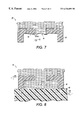
- FIG. 7 illustrates a printhead 70 with undesirable dried ink/debris 90 on its surface, whose existence may cause misdirectionality due to interference with the meniscus 36 .
- the meniscus 36 is shown to be held within orifice plate 28 of printhead 70 .
- ejected ink droplets 92 do not emit from the center 94 of meniscus 36 , resulting in undesirable marking. Therefore, the cleaning of the present invention removes the dried ink/debris in order to improve the directionality of ink droplets 92 .
- the present invention may be used in conjunction or alone with the flooding operation of capping structure 50 .
- AIP wiping station 80 when activated, AIP wiping station 80 is moved into engagement with printhead 70 .
- the AIP printhead wiping station 80 provides a two-step process to remove the dried ink/debris 90 shown in FIG. 7 .
- the ink flow rate of the printhead which normally operates, in one embodiment at 150 ml a minute, is increased to a higher rate, for example in this embodiment 190 ml a minute. As shown in FIG. 8, this increased pressure acts to flatten the meniscus 36 pushing ink out of printhead 70 .
- roller 82 is engaged over orifice 30 , while printhead 70 is moving in a first direction 100 , in this embodiment at a printhead wipe speed for high flow operation of 0.50 inches per second (ips). At the same time, roller 82 is moving in an opposite direction 102 at approximately a speed of 0.25 ips. The force with which the roller 82 is pressed against the orifice plate is approximately between 230 and 300 gmf.
- the action of wiping station 82 is two-fold.
- the first function is to dissolve dried ink/debris 90 from the orifices as well as the front surface of the printhead 70 .
- the other function is to transport the dissolved ink and contaminants away from the orifices and the front face of the printhead 70 . This is achieved by a varying combination of wet wiping; ink flow rates in the printhead, and translating the printhead at an appropriate speed during the wet wipe cycle, in a direction opposite wiping station 80 .
- a unique aspect of the wet wipe scheme of the present invention is that the meniscus unlike other ink jet technologies is on the back side of the orifice plate 28 which requires the wet wipe to extend into the structure to remove contaminants and excess ink from the orifices.
- the highly absorptive, hydrophilic and compliant material i.e. the foam or sponge in the form of a roller 82
- washing fluid container 84 of FIG. 6 the highly absorptive, hydrophilic and compliant material
- roller 82 is then dragged and squeezed over the orifice structure of the printhead to clean and remove the dried ink and debris off the orifices.
- the foam or sponge containing the debris and dirty ink is then immersed in the wash fluid 84 to remove the contamination and is next squeezed/pinched between the squeegee 86 to remove excess fluid in preparation of readying foam/sponge roller 82 for further cleaning/contact with the orifice structure of printhead 70 .
- the foam/sponge roller 82 is cleaned by passing through washing fluid container 84 and then being squeezed or pinched by squeegee 86 , to remove excess washing fluid retained from the previous washing/cleaning zone. Increasing the pressure within printhead 70 causes the ink to come out of the printhead 70 and is absorbed by foam/sponge roller 82 .
- the ink pressure within printhead 70 is decreased, as shown in FIG. 9 .
- the low ink pressure is approximately 75 ml per minute which results in retracting the meniscus 36 within printhead 70 .
- a force is applied by roller 82 , e.g. 230-300 gmf range, and minimal amounts of ink will exit the printhead 70 . This step is useful in removing any left over ink as well as assists in drying of printhead 70 .
- wiping station 80 is disengaged from printhead 70 .
- wiping station 80 may continue to rotate roller 82 through washing fluid container 84 and past engaged squeegee 86 for several additional rotations. The rotations are continued in order to ensure a complete cleaning of the roller 82 .
- squeegee 86 may be disengaged from contact with roller 82 , and roller 82 may be removed from washing fluid container 84 .
- the disengagement and movement of parts may be accomplished by known mechanical configurations.
- pressure within the printhead 70 relative to the pressure applied by roller 82 is such that ink will move out of printhead 70 and washing fluid will not pass into printhead 70 . Specifically, it is desirable that washing fluid does not enter the printhead and thereby dilute the ink. It is to be noted that in a preferred embodiment the area of cleaning would be approximately 5 mm for a particular orifice and a complete orifice plate is anticipated at being approximately 32 mm in length.
- roller 82 As an aspect of the present invention is to provide a compact cleaning device, it is desirable to minimize the size of the roller 82 .
- a further embodiment of operation includes moistening of roller 82 in washing fluid container 84 , and thereafter disengaging roller 82 and washing fluid container 84 .
- the next step rotates roller 82 through squeegee 86 a predetermined number of times in order to provide sufficient removal of liquid.
- the moistened but non-saturated roller 82 is moved into contact with the printhead 70 for cleaning.
- FIG. 10 illustrated is a second embodiment of a wiping station 120 .
- This embodiment is substantially similar to the embodiment of wiping station 80 of FIG. 6 .
- roller 82 is replaced with a belt mechanism 122 wherein a belt made of a highly absorptive, hydrophilic and compliant material such as a foam or sponge 124 is arranged around rollers 126 and 128 .
- foam/sponge belt 124 engages the washing fluid container 84 when in the area of roller 128 .
- the printhead cleaning operation described previously in connection with the wiping station 80 of FIG. 6 is equally applicable to that of the present shown embodiment of FIG. 10 .
- belt 124 is also cleaned by the wiping station 120 by a procedure discussed in connection with the cleaning of roller 82 of FIG. 6 .
- roller 82 or belt assembly 122 In use of either roller 82 or belt assembly 122 , with the speeds discussed in the previous embodiment, it is anticipated that one pass of the wiping station 80 across the surface of printhead 70 is from 2-5 seconds. It has also been determined by the inventors that it is desirable to clean a printhead 70 at least once a day in a printing system. Since there will be two passes for a cleaning process, the entire cleaning process would result in engagement of the roller 82 or belt 122 with printhead 70 , for approximately 4-10 seconds a day.
- an appropriate absorption rate for an anticipated embodiment is within the range of 50-250 seconds hydrophilicity (also called wet-out, a standard commercial foam specification, measuring absorption time of a known volume of water), and more preferably between 100-110.
- the present invention has applied optimal characteristics for desired cleaning with minimal ink loss.
- a relatively small amount of ink is removed from the printhead during each printing process.
- the inventors have found that less than 1 ⁇ 4ml of ink is used during each cleaning process, i.e. including both a first and second pass.
- Cleaning station 80 may be used to clean more than a single printhead 70 , and may also be employed to clean printheads of different colors. This capability exists due to the fact that the cleaning process ensures that cleaning fluid does not enter into a printhead 70 being cleaned. Since the washing fluid does not enter the printhead 70 , there is an assurance that the ink in the printhead will not be diluted with the cleaning fluid or other colored ink. Thus, as long as the printheads are using inks which are compatible when mixed together within the washing fluid, the present invention may be used to clean a variety of printheads including those employing different colors.
- washing fluid may be used in the cleaning process which has up to 15% of its volume as ink.
- roller 82 and squeegee 86 shown in side view are roller 82 and squeegee 86 .
- roller 82 is depicted in an engaged position during printhead cleaning, wherein squeegee 86 removes excess moisture from roller 82 .
- roller 82 moved out of engagement with squeegee 86 . This procedure exists so as not to maintain squeegee 86 and roller 82 in permanent contact.
- the amount of time where actual cleaning occurs within the lifetime of the wiping station 80 is minimal, i.e. 10 seconds a day.
- FIG. 12 illustrates a further embodiment of this concept, but wherein roller 82 is in a fixed position and squeegee 86 is moved out of engagement.
- FIG. 13 illustrates a concept wherein the washing fluid container 84 is moved out of engagement with the roller 82 . It is to be appreciated that with regard to FIG. 11, since roller 82 is movable the present invention may be designed to have the roller 82 removed from washing fluid container 84 .
- FIGS. 14 and 15 Similar concepts as previously discussed, but in connection with belt assembly 122 are illustrated.
- entire belt assembly 122 is moved out of engagement with squeegee 86 while squeegee 86 is fixed.
- first roller 126 is moved so as to take belt 124 out of engagement with squeegee 86 .
- FIG. 16 illustrates a concept where the belt assembly 122 is in a fixed position and it is squeegee roller 186 which is motivated into and out of engagement.
- FIG. 17 shows an arrangement where washing fluid container 84 is moved out of engagement with belt assembly 122 .
Abstract
Description
Claims (19)
Priority Applications (1)
| Application Number | Priority Date | Filing Date | Title |
|---|---|---|---|
| US09/448,008 US6336699B1 (en) | 1999-11-23 | 1999-11-23 | Self-cleaning wet wipe method and apparatus for cleaning orifices in an AIP type printhead |
Applications Claiming Priority (1)
| Application Number | Priority Date | Filing Date | Title |
|---|---|---|---|
| US09/448,008 US6336699B1 (en) | 1999-11-23 | 1999-11-23 | Self-cleaning wet wipe method and apparatus for cleaning orifices in an AIP type printhead |
Publications (1)
| Publication Number | Publication Date |
|---|---|
| US6336699B1 true US6336699B1 (en) | 2002-01-08 |
Family
ID=23778648
Family Applications (1)
| Application Number | Title | Priority Date | Filing Date |
|---|---|---|---|
| US09/448,008 Expired - Lifetime US6336699B1 (en) | 1999-11-23 | 1999-11-23 | Self-cleaning wet wipe method and apparatus for cleaning orifices in an AIP type printhead |
Country Status (1)
| Country | Link |
|---|---|
| US (1) | US6336699B1 (en) |
Cited By (22)
| Publication number | Priority date | Publication date | Assignee | Title |
|---|---|---|---|---|
| US20040206872A1 (en) * | 2001-08-23 | 2004-10-21 | Andreas Peiker | Holder for an electronic device |
| US20040263557A1 (en) * | 2003-06-26 | 2004-12-30 | Xerox Corporation | Single roller cleaning systems for fluid ejector system |
| US20060209152A1 (en) * | 2005-03-16 | 2006-09-21 | Hewlett-Packard Development Company, Lp | Web |
| US20070081011A1 (en) * | 2005-10-11 | 2007-04-12 | Silverbrook Research Pty Ltd | Printhead maintenance station comprising maintenance roller and ink removal system |
| US20070080985A1 (en) * | 2005-10-11 | 2007-04-12 | Silverbrook Research Pty Ltd | Method of cleaning a printhead using cleaning liquid |
| WO2007112885A1 (en) * | 2006-03-31 | 2007-10-11 | Krishna Uibel | Method and apparatus for producing three-dimensional ceramic mouldings |
| US20070242121A1 (en) * | 2006-04-12 | 2007-10-18 | Hewlett-Packard Development Company Lp | Web |
| US20080024545A1 (en) * | 2006-07-31 | 2008-01-31 | Silverbrook Research Pty Ltd | Method of removing particulates from a printhead using a liquid foam |
| US20090301550A1 (en) * | 2007-12-07 | 2009-12-10 | Sunprint Inc. | Focused acoustic printing of patterned photovoltaic materials |
| US20100079536A1 (en) * | 2006-07-31 | 2010-04-01 | Silverbrook Research Pty Ltd | Printhead maintenance system for applying foam to printhead |
| AU2006301900B2 (en) * | 2005-10-11 | 2010-05-27 | Memjet Technology Limited | Printhead maintenance assembly comprising maintenance roller and cleaning mechanism |
| US20100184244A1 (en) * | 2009-01-20 | 2010-07-22 | SunPrint, Inc. | Systems and methods for depositing patterned materials for solar panel production |
| US20100201724A1 (en) * | 2009-02-12 | 2010-08-12 | Sony Corporation | Liquid discharge apparatus and method of controlling liquid discharge apparatus |
| US20100271442A1 (en) * | 2006-07-31 | 2010-10-28 | Silverbrook Research Pty Ltd | Printer with foaming system for cleaning ejecting face |
| US20100309251A1 (en) * | 2009-06-03 | 2010-12-09 | Georg Cramm | Maintenance unit for print head |
| US20110279535A1 (en) * | 2010-05-17 | 2011-11-17 | Silverbrook Research Pty Ltd | Maintenance apparatus having rotatable wiper and transfer rollers for printhead |
| US8540340B2 (en) | 2010-05-17 | 2013-09-24 | Zamtec Ltd | Printer having modular maintenance sled |
| CN103847234A (en) * | 2012-11-30 | 2014-06-11 | 精工爱普生株式会社 | Ink jet recording apparatus |
| CN103847230A (en) * | 2012-11-30 | 2014-06-11 | 精工爱普生株式会社 | Ink jet recording apparatus |
| US20140292916A1 (en) * | 2013-03-27 | 2014-10-02 | Seiko Epson Corporation | Head cleaning method and liquid discharging apparatus |
| JP2018030347A (en) * | 2016-08-26 | 2018-03-01 | 株式会社リコー | Liquid discharge device |
| CN116749650A (en) * | 2023-07-05 | 2023-09-15 | 默克韦尔传动技术(苏州)有限公司 | Frequency converter production and processing is with spouting a yard printing device convenient to location direction |
Citations (4)
| Publication number | Priority date | Publication date | Assignee | Title |
|---|---|---|---|---|
| DE3042998A1 (en) * | 1980-11-14 | 1982-07-01 | Olympia Werke Ag, 2940 Wilhelmshaven | Inking head nozzle cover - has cleaning cushion impregnated with moistening agent and with wiper edges |
| US5027134A (en) | 1989-09-01 | 1991-06-25 | Hewlett-Packard Company | Non-clogging cap and service station for ink-jet printheads |
| US5798775A (en) * | 1991-01-11 | 1998-08-25 | Canon Kabushiki Kaisha | Ink jet recording apparatus |
| US5856834A (en) * | 1996-12-12 | 1999-01-05 | Pitney Bowes Inc. | Device and method for conserving ink consumption in an ink cartridge of a postage meter |
-
1999
- 1999-11-23 US US09/448,008 patent/US6336699B1/en not_active Expired - Lifetime
Patent Citations (4)
| Publication number | Priority date | Publication date | Assignee | Title |
|---|---|---|---|---|
| DE3042998A1 (en) * | 1980-11-14 | 1982-07-01 | Olympia Werke Ag, 2940 Wilhelmshaven | Inking head nozzle cover - has cleaning cushion impregnated with moistening agent and with wiper edges |
| US5027134A (en) | 1989-09-01 | 1991-06-25 | Hewlett-Packard Company | Non-clogging cap and service station for ink-jet printheads |
| US5798775A (en) * | 1991-01-11 | 1998-08-25 | Canon Kabushiki Kaisha | Ink jet recording apparatus |
| US5856834A (en) * | 1996-12-12 | 1999-01-05 | Pitney Bowes Inc. | Device and method for conserving ink consumption in an ink cartridge of a postage meter |
Cited By (63)
| Publication number | Priority date | Publication date | Assignee | Title |
|---|---|---|---|---|
| US7280656B2 (en) * | 2001-08-23 | 2007-10-09 | Andreas Peiker | Holder for an electronic device |
| US20040206872A1 (en) * | 2001-08-23 | 2004-10-21 | Andreas Peiker | Holder for an electronic device |
| US20040263557A1 (en) * | 2003-06-26 | 2004-12-30 | Xerox Corporation | Single roller cleaning systems for fluid ejector system |
| US6863366B2 (en) | 2003-06-26 | 2005-03-08 | Xerox Corporation | Single roller cleaning systems for fluid ejector system |
| US20060209152A1 (en) * | 2005-03-16 | 2006-09-21 | Hewlett-Packard Development Company, Lp | Web |
| US7770518B2 (en) | 2005-03-16 | 2010-08-10 | Hewlett-Packard Development Company, L.P. | Web apparatus for cleaning arcuate printhead arrangement |
| US20070080985A1 (en) * | 2005-10-11 | 2007-04-12 | Silverbrook Research Pty Ltd | Method of cleaning a printhead using cleaning liquid |
| AU2006301900B2 (en) * | 2005-10-11 | 2010-05-27 | Memjet Technology Limited | Printhead maintenance assembly comprising maintenance roller and cleaning mechanism |
| US20070081014A1 (en) * | 2005-10-11 | 2007-04-12 | Silverbrook Research Pty Ltd | Printhead maintenance assembly comprising maintenance roller and cleaning mechanism |
| US20070081010A1 (en) * | 2005-10-11 | 2007-04-12 | Silverbrook Research Pty Ltd | Printhead maintenance assembly comprising first and second rollers |
| US20070081011A1 (en) * | 2005-10-11 | 2007-04-12 | Silverbrook Research Pty Ltd | Printhead maintenance station comprising maintenance roller and ink removal system |
| US20100194818A1 (en) * | 2005-10-11 | 2010-08-05 | Silverbrook Research Pty Ltd. | Inkjet printer with reciprocally movable maintenance station |
| US7971958B2 (en) | 2005-10-11 | 2011-07-05 | Silverbrook Research Pty Ltd | Inkjet printer with maintenance assembly having non-absorbent roller |
| US20100141706A1 (en) * | 2005-10-11 | 2010-06-10 | Silverbrook Research Pty Ltd | Non-contact method of maintaining inkjet printhead |
| US20070081012A1 (en) * | 2005-10-11 | 2007-04-12 | Silverbrook Research Pty Ltd | Method of maintaining a printhead using a maintenance roller and ink removal system mounted on a chassis |
| US8075090B2 (en) | 2005-10-11 | 2011-12-13 | Silverbrook Research Pty Ltd | Method of maintaining inkjet printhead using non-contact roller |
| US7637588B2 (en) * | 2005-10-11 | 2009-12-29 | Silverbrook Research Pty Ltd | Printhead maintenance assembly comprising maintenance roller and cleaning mechanism |
| US7648222B2 (en) | 2005-10-11 | 2010-01-19 | Silverbrook Research Pty Ltd | Printhead maintenance station comprising maintenance roller and ink removal system |
| US20100013888A1 (en) * | 2005-10-11 | 2010-01-21 | Silverbrook Research Pty Ltd | Method Of Maintaining Printhead Using Maintenance Roller |
| US7658463B2 (en) * | 2005-10-11 | 2010-02-09 | Silverbrook Research Pty Ltd | Printhead maintenance assembly comprising first and second rollers |
| US20100220144A1 (en) * | 2005-10-11 | 2010-09-02 | Silverbrook Research Pty Ltd | Method of maintaining inkjet printhead using non-contact roller |
| US20100073422A1 (en) * | 2005-10-11 | 2010-03-25 | Silverbrook Research Pty Ltd | Inkjet Printer With Maintenance Assembly Having Non-Absorbent Roller |
| US8002381B2 (en) | 2005-10-11 | 2011-08-23 | Silverbrook Research Pty Ltd | Inkjet printer with reciprocally movable maintenance station |
| US7699433B2 (en) * | 2005-10-11 | 2010-04-20 | Silverbrook Research Pty Ltd | Method of maintaining a printhead using a maintenance roller and ink removal system mounted on a chassis |
| US7722153B2 (en) * | 2005-10-11 | 2010-05-25 | Silverbrook Research Pty Ltd | Method of cleaning a printhead using cleaning liquid |
| US20100040767A1 (en) * | 2006-03-31 | 2010-02-18 | Horst Fischer | Process and Apparatus for Producing Three-Dimensional Shaped Ceramic Bodies |
| US8409655B2 (en) | 2006-03-31 | 2013-04-02 | Horst Fischer | Process and apparatus for producing three-dimensional shaped ceramic bodies |
| WO2007112885A1 (en) * | 2006-03-31 | 2007-10-11 | Krishna Uibel | Method and apparatus for producing three-dimensional ceramic mouldings |
| US8529017B2 (en) | 2006-04-12 | 2013-09-10 | Hewlett-Packard Development Company, L.P. | Printhead cleaning web assembly |
| US20070242121A1 (en) * | 2006-04-12 | 2007-10-18 | Hewlett-Packard Development Company Lp | Web |
| US7815302B2 (en) | 2006-04-12 | 2010-10-19 | Hewlett-Packard Development Company, L.P. | Printhead cleaning web assembly |
| US20090289988A1 (en) * | 2006-07-31 | 2009-11-26 | Silverbrook Research Pty Ltd | Method Of Cleaning A Printhead Using Liquid Foam |
| US8382234B2 (en) | 2006-07-31 | 2013-02-26 | Zamtec Ltd | Printhead maintenance system for applying foam to printhead |
| US20100271442A1 (en) * | 2006-07-31 | 2010-10-28 | Silverbrook Research Pty Ltd | Printer with foaming system for cleaning ejecting face |
| US20080024545A1 (en) * | 2006-07-31 | 2008-01-31 | Silverbrook Research Pty Ltd | Method of removing particulates from a printhead using a liquid foam |
| US7922285B2 (en) * | 2006-07-31 | 2011-04-12 | Silverbrook Research Pty Ltd | Method of cleaning a printhead using liquid foam |
| US7581812B2 (en) * | 2006-07-31 | 2009-09-01 | Silverbrook Research Pty Ltd | Method of removing particulates from a printhead using a liquid foam |
| US20100079536A1 (en) * | 2006-07-31 | 2010-04-01 | Silverbrook Research Pty Ltd | Printhead maintenance system for applying foam to printhead |
| US8100517B2 (en) | 2006-07-31 | 2012-01-24 | Silverbrook Research Pty Ltd | Printer with foaming system for cleaning ejecting face |
| US20090301550A1 (en) * | 2007-12-07 | 2009-12-10 | Sunprint Inc. | Focused acoustic printing of patterned photovoltaic materials |
| US20100184244A1 (en) * | 2009-01-20 | 2010-07-22 | SunPrint, Inc. | Systems and methods for depositing patterned materials for solar panel production |
| US20100201724A1 (en) * | 2009-02-12 | 2010-08-12 | Sony Corporation | Liquid discharge apparatus and method of controlling liquid discharge apparatus |
| US8641166B2 (en) | 2009-06-03 | 2014-02-04 | Novartis Ag | Maintenance unit for print head |
| US8408672B2 (en) * | 2009-06-03 | 2013-04-02 | Novartis Ag | Maintenance unit for print head |
| US20100309251A1 (en) * | 2009-06-03 | 2010-12-09 | Georg Cramm | Maintenance unit for print head |
| US8562104B2 (en) | 2010-05-17 | 2013-10-22 | Zamtec Ltd | Maintenance system having cleanable wiper for printhead |
| US8851628B2 (en) | 2010-05-17 | 2014-10-07 | Memjet Technology Ltd. | Wiping device having on-board mechanism for rotating wiper roller for printhead |
| US20110279535A1 (en) * | 2010-05-17 | 2011-11-17 | Silverbrook Research Pty Ltd | Maintenance apparatus having rotatable wiper and transfer rollers for printhead |
| US9221261B2 (en) | 2010-05-17 | 2015-12-29 | Memjet Technology Ltd. | Printer having sled providing wiping, capping and platen modules |
| US9150034B2 (en) | 2010-05-17 | 2015-10-06 | Memjet Technology Ltd. | Apparatus for assisting printing having proximal wick |
| US8764141B2 (en) | 2010-05-17 | 2014-07-01 | Zamtec Ltd | System for shaping media at printhead |
| US8770711B2 (en) | 2010-05-17 | 2014-07-08 | Zamtec Limited | Printhead maintenance system having wiper module |
| US8833919B2 (en) | 2010-05-17 | 2014-09-16 | Memjet Technology Ltd. | Method of shaping media at printhead |
| US8540340B2 (en) | 2010-05-17 | 2013-09-24 | Zamtec Ltd | Printer having modular maintenance sled |
| CN103847230A (en) * | 2012-11-30 | 2014-06-11 | 精工爱普生株式会社 | Ink jet recording apparatus |
| CN103847234A (en) * | 2012-11-30 | 2014-06-11 | 精工爱普生株式会社 | Ink jet recording apparatus |
| CN103847234B (en) * | 2012-11-30 | 2016-05-04 | 精工爱普生株式会社 | Ink-jet recording apparatus |
| CN103847230B (en) * | 2012-11-30 | 2016-06-08 | 精工爱普生株式会社 | Ink-jet recording device |
| US20140292916A1 (en) * | 2013-03-27 | 2014-10-02 | Seiko Epson Corporation | Head cleaning method and liquid discharging apparatus |
| US9139007B2 (en) * | 2013-03-27 | 2015-09-22 | Seiko Epson Corporation | Head cleaning method and liquid discharging apparatus |
| JP2018030347A (en) * | 2016-08-26 | 2018-03-01 | 株式会社リコー | Liquid discharge device |
| CN116749650A (en) * | 2023-07-05 | 2023-09-15 | 默克韦尔传动技术(苏州)有限公司 | Frequency converter production and processing is with spouting a yard printing device convenient to location direction |
| CN116749650B (en) * | 2023-07-05 | 2024-03-26 | 默克韦尔传动技术(苏州)有限公司 | Frequency converter production and processing is with spouting a yard printing device convenient to location direction |
Similar Documents
| Publication | Publication Date | Title |
|---|---|---|
| US6336699B1 (en) | Self-cleaning wet wipe method and apparatus for cleaning orifices in an AIP type printhead | |
| US5184147A (en) | Ink jet print head maintenance system | |
| US6350012B1 (en) | Method and apparatus for cleaning/maintaining of an AIP type printhead | |
| US5949454A (en) | Ink jet head, ink jet head cartridge, ink jet recording apparatus and method for making ink jet head | |
| US5670996A (en) | Thermal ink jet recording device and method of cleaning a recording head | |
| US10730305B2 (en) | Inkjet printing system with non-contact cleaning station | |
| JP2011079170A (en) | Cleaner cartridge, cleaning device and image forming apparatus | |
| US9296210B2 (en) | Liquid ejecting apparatus | |
| US6416161B1 (en) | Wiper blade mechanism for ink jet printers | |
| JPH0671904A (en) | Color ink-jet recording apparatus | |
| JP2011079192A (en) | Liquid jetting apparatus | |
| JPH02198859A (en) | Ink-jet recorder with ink cleaning member | |
| JP4101050B2 (en) | Inkjet recording device | |
| JPH05162320A (en) | Ink jet recording apparatus, recording head therein and method for cleaning cap member | |
| JP3024368B2 (en) | Cleaning device for inkjet recording head | |
| US6517187B1 (en) | Method and apparatus for cleaning residual ink from printhead nozzle faces | |
| JPH11342621A (en) | Ink jet recording apparatus | |
| JPH03240554A (en) | Ink jet recording device | |
| JP2007130806A (en) | Inkjet recorder | |
| US6491371B1 (en) | Ink blotter for an ink jet printer maintenance station providing increased ink carrying capacity | |
| JPH11170566A (en) | Image forming method and apparatus therefor | |
| JP2006305772A (en) | Inkjet recorder, wiping method, and wiping blade | |
| US10737495B2 (en) | Liquid ejecting apparatus and maintenance method of liquid ejecting apparatus | |
| JP7323029B2 (en) | LIQUID EJECTING DEVICE, MAINTENANCE METHOD OF LIQUID EJECTING DEVICE | |
| JP7139885B2 (en) | LIQUID EJECTING DEVICE, MAINTENANCE METHOD OF LIQUID EJECTING DEVICE |
Legal Events
| Date | Code | Title | Description |
|---|---|---|---|
| AS | Assignment |
Owner name: XEROX CORPORATION, CONNECTICUT Free format text: ASSIGNMENT OF ASSIGNORS INTEREST;ASSIGNORS:SARKISSIAN, SHAHIN;ROY, JOY;REEL/FRAME:010583/0471 Effective date: 19991123 |
|
| FEPP | Fee payment procedure |
Free format text: PAYOR NUMBER ASSIGNED (ORIGINAL EVENT CODE: ASPN); ENTITY STATUS OF PATENT OWNER: LARGE ENTITY |
|
| STCF | Information on status: patent grant |
Free format text: PATENTED CASE |
|
| AS | Assignment |
Owner name: BANK ONE, NA, AS ADMINISTRATIVE AGENT, ILLINOIS Free format text: SECURITY INTEREST;ASSIGNOR:XEROX CORPORATION;REEL/FRAME:013153/0001 Effective date: 20020621 |
|
| AS | Assignment |
Owner name: JPMORGAN CHASE BANK, AS COLLATERAL AGENT, TEXAS Free format text: SECURITY AGREEMENT;ASSIGNOR:XEROX CORPORATION;REEL/FRAME:015134/0476 Effective date: 20030625 Owner name: JPMORGAN CHASE BANK, AS COLLATERAL AGENT,TEXAS Free format text: SECURITY AGREEMENT;ASSIGNOR:XEROX CORPORATION;REEL/FRAME:015134/0476 Effective date: 20030625 |
|
| FPAY | Fee payment |
Year of fee payment: 4 |
|
| FPAY | Fee payment |
Year of fee payment: 8 |
|
| FPAY | Fee payment |
Year of fee payment: 12 |
|
| AS | Assignment |
Owner name: XEROX CORPORATION, NEW YORK Free format text: RELEASE BY SECURED PARTY;ASSIGNOR:BANK ONE, NA;REEL/FRAME:034719/0704 Effective date: 20030625 Owner name: XEROX CORPORATION, NEW YORK Free format text: RELEASE BY SECURED PARTY;ASSIGNOR:JPMORGAN CHASE BANK, N.A.;REEL/FRAME:034720/0430 Effective date: 20061204 |
|
| AS | Assignment |
Owner name: XEROX CORPORATION, CONNECTICUT Free format text: RELEASE BY SECURED PARTY;ASSIGNOR:JPMORGAN CHASE BANK, N.A. AS SUCCESSOR-IN-INTEREST ADMINISTRATIVE AGENT AND COLLATERAL AGENT TO JPMORGAN CHASE BANK;REEL/FRAME:066728/0193 Effective date: 20220822 |