US6332881B1 - Surgical ablation tool - Google Patents
Surgical ablation tool Download PDFInfo
- Publication number
- US6332881B1 US6332881B1 US09/387,889 US38788999A US6332881B1 US 6332881 B1 US6332881 B1 US 6332881B1 US 38788999 A US38788999 A US 38788999A US 6332881 B1 US6332881 B1 US 6332881B1
- Authority
- US
- United States
- Prior art keywords
- assembly
- tip
- plane
- deflection
- tool
- Prior art date
- Legal status (The legal status is an assumption and is not a legal conclusion. Google has not performed a legal analysis and makes no representation as to the accuracy of the status listed.)
- Expired - Fee Related
Links
Images


Classifications
-
- A—HUMAN NECESSITIES
- A61—MEDICAL OR VETERINARY SCIENCE; HYGIENE
- A61B—DIAGNOSIS; SURGERY; IDENTIFICATION
- A61B18/00—Surgical instruments, devices or methods for transferring non-mechanical forms of energy to or from the body
- A61B18/04—Surgical instruments, devices or methods for transferring non-mechanical forms of energy to or from the body by heating
- A61B18/12—Surgical instruments, devices or methods for transferring non-mechanical forms of energy to or from the body by heating by passing a current through the tissue to be heated, e.g. high-frequency current
- A61B18/14—Probes or electrodes therefor
- A61B18/1402—Probes for open surgery
-
- A—HUMAN NECESSITIES
- A61—MEDICAL OR VETERINARY SCIENCE; HYGIENE
- A61B—DIAGNOSIS; SURGERY; IDENTIFICATION
- A61B18/00—Surgical instruments, devices or methods for transferring non-mechanical forms of energy to or from the body
- A61B18/04—Surgical instruments, devices or methods for transferring non-mechanical forms of energy to or from the body by heating
- A61B18/12—Surgical instruments, devices or methods for transferring non-mechanical forms of energy to or from the body by heating by passing a current through the tissue to be heated, e.g. high-frequency current
- A61B18/14—Probes or electrodes therefor
- A61B18/1492—Probes or electrodes therefor having a flexible, catheter-like structure, e.g. for heart ablation
Definitions
- This invention generally relates to the treatment of cardiac arrhythmia and atrial fibrillation.
- this invention is a surgical ablation tool for treating atrial fibrillation by creating lesions in cardiac tissue during open heart or open chest surgery.
- Atrial fibrillation is characterized by the irregular and very rapid beating of the heart's atrial chambers and results when the normal electrical conduction system of the atria malfunctions, leading to irregular and chaotic electrical signals.
- AF Atrial fibrillation
- the regular pumping action of the atria is replaced by irregular, disorganized and quivering spasms of atrial tissue. These spasms may lead to reduced blood flow, blood clots, stroke and even death.
- This malfunction results in the failure of the atria to fill the ventricles completely and, consequently, the failure of the heart to pump adequate amounts of blood to the body.
- AF becomes symptomatic, it is typically associated with significant morbidity related to reduced blood flow.
- the greatest concern is that the reduced cardiac output can lead to blood pooling in the atria and the formation of blood clots. Blood clots in the left atrium can dislodge and travel through the bloodstream to the brain, resulting in stroke and even death.
- AF In the United States, AF currently affects an estimated two million people, with approximately 160,000 new cases being diagnosed each year. About 1.5 million outpatient visits and more than 200,000 patient admissions per year in the United States are associated with AF. AF is responsible for over 70,000 strokes each year in the United States alone; the annual cost of treating these patients is more than $3.6 billion. The cost of drug treatment for AF alone is estimated to be in excess of $400 million worldwide each year.
- Antiarrhythmic and anticoagulant drugs such as sodium and calcium channel blockers
- drugs which reduce the Beta-adrenergic activity are the most common treatment for AF. These drugs are used to control AF by restoring the heart's natural rhythm and limiting the natural clotting mechanism of the blood.
- antiarrhythmic drug therapy often becomes less effective over time, with approximately half of the patients eventually developing resistance.
- antiarrhythmic drugs can have severe side effects, including pulmonary fibrosis and impaired liver function.
- AF is external cardioversion, or the application of strong electrical current under general anesthesia. This treatment is usually only effective for a limited period of time as well. Implantable atrial defibrillators are being investigated to detect the onset of AF internally and then deliver an electrical shock to convert the heart back to normal rhythm. Although the preliminary results of clinical studies indicate that this approach may be feasible, AF is not cured with this approach. There are also significant problems with this treatment, including pain tolerance, reversion to AF and creation of ventricular tachycardia as a result of the electrical shock.
- AV node Purposeful destruction of the Atrio-Ventricular (AV) node followed by implantation of a pacemaker is typically a treatment of last resort for AF patients, but does not cure or treat the AF itself Since atrial function remains poor following the procedure, chronic anticoagulant therapy is generally required.
- Another therapy for AF is an open heart operation.
- a surgeon makes several slices through the wall of the atrium with a scalpel and then sews the cuts back together, creating a scar pattern.
- the scars isolate and contain the chaotic electrical impulses to control and channel the electrical signal emanating from the SA node.
- RF ablation catheters are used to form thin, continuous linear scars in various locations in the atria. This procedure has the promise of safely treating AF with significantly reduced trauma.
- One treatment combines the advantages of the open heart “maze” procedure and RF catheter-based treatment such that lesions are created in an open heart environment with one or more RF electrodes and not the surgeon's scalpel.
- RF catheter-based treatment such that lesions are created in an open heart environment with one or more RF electrodes and not the surgeon's scalpel.
- ablation device which can be used as a surgical tool that assures adequate tissue contact prior to ablation but which is flexible enough to create both straight and curved lines of conduction block, etc. in endocardial and epicardial applications.
- This invention is directed to a surgical ablation tool suitable for forming linear lesions on cardiac tissue during open heart or open chest surgery to treat atrial fibrillation and flutter.
- the deflectable surgical ablation assembly includes a main body comprising a semi-rigid elongate member defining a lumen and having a distal end and a proximal end. This member forms an angle at its distal end, typically between 90 degrees and 180 degrees, which defines a first plane of deflection.
- a multilumen flexible tip is distally fixed to the main body and houses a deflection mechanism for deflecting the tip about a second plane of deflection, typically substantially perpendicular to the first plane, and at least one electrode disposed on an outer surface of the tip.
- the deflection mechanism consists of a pull wire attached to a linear spring.
- the tip is capable of deflecting to the point that the tip distal end physically contacts a more proximal portion of the ablation assembly.
- a nonactive atraumatic tip or cap is typically fixed distally on the flexible tip as well.
- a handle is proximally connected to the main body for manipulating the pull wire.
- the handle can include a connector for transmitting electromagnetic energy between the tip and a remote device, such as an electrocardiogram recording system, a radiofrequency power supply, and the like.
- the tool distal tip can have one or more apertures through the tip exterior surface and connected to a lumen defined in the tip.
- Fiber optic or other data transmission cables can be disposed in the main body for transmitting data related to the patient from an outside device.
- the assembly may also be irrigated to deliver cooling fluids to the tip and the electrode or electrodes, and one or more temperature sensing devices can be incorporated into the device on the tip as well.
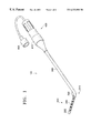
- FIG. 1 is a perspective of the surgical ablation tool of the present invention.
- FIG. 2 is a schematic of the distal portion of the tool detailing in phantom deflection of the electrode region.
- FIG. 3 is a longitudinal cross section of a proximal portion of the tool electrode region detailing the deflection mechanism and interior structure.
- FIG. 4 is a transverse cross section of a proximal portion of the tool electrode taken along the lines 4 — 4 .
- FIG. 5 is a transverse cross section of a more distal portion of the tool electrode taken along the lines 5 — 5 .
- FIG. 6 is a longitudinal cross section of a distal portion of the tool electrode region.
- This invention includes a surgical ablation catheter, or tool, which is most suitable for use in ablating cardiac tissue during open heart or open chest surgery.
- This relatively short device (in comparison to conventional ablation catheters) has a handle connected to an angled rigid or semi-rigid shaft which terminates in a deflectable active electrode region.
- the electrode region is deflectable in a plane generally perpendicular to the plane of deflection defined by the distal end of the shaft.
- One or more electrodes are disposed on the active electrode region for ablating cardiac tissue.
- the handle is useable for maneuvering the tool and deflecting the active electrode region.
- the tool of the invention can be used in a variety of applications, including open heart surgery (for endocardial lesion formation) and open chest surgery (for epicardial lesion formation).
- the shaft of the catheter is useful to ensure the active electrode region adequately contacts the tissue of interest so that lesions can be created as safely and effectively as possible. Due to the unique shape and deflection capability of the tool, one particularly useful application of this catheter is in creating both straight and curved lines of conduction block encircling the pulmonary veins, simulating the conventional surgical “maze” procedure.
- the tool is best used during open heart surgery, for example during mitral valve replacement.
- the left atrium, right atrium, or both are exposed using conventional techniques for visual placement of the catheter.
- Various tissue can be adequately reached by the tool.
- the tool will best be used around the pulmonary veins, various septal lines and various right atria lines (including, e.g., Interior Vena Cava (IVC) to Superior Vena Cava (SVC), Isthmus, etc.).
- FIG. 1 depicts a short, agile and responsive catheter or tool suitable for surgically ablating cardiac tissue.
- tool 100 comprises handle 400 , shaft 300 , and distal flexible electrode region or tip 200 .
- Deflection handle 400 is designed so to allow the surgeon to grip and manipulate tool 100 with maximum ease. It includes a control knob 410 or the like for manipulating the flexible distal electrode region 200 . Handle 400 may optionally contain a port or connector 420 for coupling the catheter 100 with one or more number of external devices such as, e.g., an electrocardiogram recording system, an RF power supply, or a remote visualization system (via a fiber optic or traditional data link).
- any handle suitable for interfacing with the user and allowing manipulation of the catheter 100 is within the scope of the invention.
- the handle described in pending U.S. patent application Ser. No. 09/001,249, entitled “Deflectable Guiding Catheter” to Qin et al., filed Dec. 30, 1997, the contents of which are herein incorporated by reference in their entirety, can be used in the present invention.
- main body or semi-rigid shaft 300 Connected to the handle 400 is main body or semi-rigid shaft 300 which comprises the majority of the length of ablation tool 100 .
- Shaft 300 which is rigid or semi-rigid in comparison to distal tip 200 , has a proximal end, a distal end, and a lumen (not shown in FIG. 1 ).
- the distal end of shaft 300 is characterized by the presence of an angled shaft region 310 .
- Angled region 310 defines an angle 340 generally greater than about 90 degrees so that the entire distal electrode region 200 is angled with respect to the rest of catheter 100 as shown in FIG. 1 .
- This angle 340 defines a plane of deflection that allows the user to access areas in the cardiac anatomy that are otherwise difficult to reach.
- Distal tip 200 is disposed distally of shaft 300 .
- Distal tip 200 is characterized by its higher flexibility in comparison to that of rigid or semi-rigid shaft 300 , its angled disposition relative to the majority of shaft 300 , its manipulability for deflection, and the presence of at least one electrode 260 . As is shown in FIG. 1, five such electrodes 260 are preferably disposed on tip 200 . Also shown is an atraumatic nonactive distal tip or cap 282 disposed on the distalmost end of electrode region 200 .
- Electrode region 200 is schematically shown in FIG. 2 in five different positions for purposes of example only. As can be seen, in its straight, undeflected position A, tip 200 extends distally in the same direction as the portion of shaft 300 distal of bend 310 .
- the tool 100 can be configured to default to this position such that when knob 410 (or other manipulation device) is in a resting position, tip 200 will assume a position approximating position A as depicted in FIG. 2 .
- the catheter 100 can be manufactured or set by the user (such as via a locking mechanism or the like) so that distal end 200 defaults to any position into which tip 200 is capable of deflection.
- the various positions B, C, D, and E are shown in phantom to demonstrate the progressively more severe angles of deflection for tip 200 upon manipulation of the deflection mechanism.
- the most severe deflection in FIG. 2 is shown in position E, where tip 200 is deflected such that the distal end of tip 200 may contact tool 100 at a distal portion of shaft 300 , forming a closed loop.
- tip 200 deflects in FIG. 2 in a gentle U-shaped mode.
- any number of different forms can be realized by tip 200 within the scope of the invention. This enables tip 200 to adequately contact tissue having a variety of different surface shapes, allowing the tool to be used in various difficult-to-reach areas of the heart.
- distal electrode tip 200 be deflectable in a single plane 120 .
- plane 120 is generally perpendicular to a plane 140 defined by, and parallel to, the distal surface 320 of shaft 300 .
- planes 120 and 140 be perpendicular to each other as shown in FIG. 2; the angle between planes 120 and 140 can vary from zero degrees to 180 degrees.
- planes 120 and 140 be different; i.e., that they be oriented to one another at some angle greater than zero degrees and less than 180 degrees. More preferably, these planes are disposed at an angle of between 70 and 110 degrees to one another. Most preferable is an angle of about 90 degrees.
- FIGS. 3-5 various cross sections of the catheter 100 are shown in the vicinity of the junction between shaft 300 and distal electrode region or tip 200 .
- FIG. 3 displays this region of catheter 100 in longitudinal cross section.
- First hypotube or shaft 300 is shown at bend or elbow 310 defining an angle 340 .
- angle 340 is generally greater than 90 degrees. It is preferable that angle 340 be between about 80 degrees and 180 degrees; more preferably between about 90 degrees and 120 degrees, and most preferably about 110 degrees.
- First hypotube 300 is relatively short, having a total length generally between about 2 and 20 inches. This length allows a physician user to employ catheter 100 easily during surgery. It is preferable that the total length of shaft 300 be between about 4 and 8 inches; most preferably about 6 inches. The particular length of shaft 300 will depend on the particular application and conditions under which ablation tool 100 is employed.
- First hypotube shaft 300 has an outer diameter of between about 0.05 and 0.20 inch; more preferably, between about 0.09 and 0.15 inch; most preferably about 0.11 inch. It generally has a wall thickness of between about 0.01 and 0.05 inch, more preferably between about 0.02 and 0.03 inch; most preferably about 0.024 inch.
- hypotube Although we refer to the term “hypotube” throughout the specification, the invention is not so limited. Any appropriate surgical tubing having the correct physical and structural characteristics (e.g., strength, stiffness, etc.) is suitable.
- Shaft 300 can be made from any material suitable to meet the performance requirements of catheter 100 .
- hypotube 300 is stainless steel. It also can be made from, in whole or in combination, metals such as iridium, platinum, palladium, rhodium, gold, tungsten, titanium, tantalum, nickel, and alloys thereof.
- Shaft 300 may also be made from any number of suitable relatively rigid or semi-rigid polymers, alloys or mixtures thereof.
- shaft 300 tubing may be a polyamide (such as the Nylons), high density polyethylene (HDPE), polypropylene, polyvinylchloride, various fluorocarbon polymers (PTFE, FEP, vinylidene fluoride, etc.), polysulfones, or the like. Blends, alloys, mixtures, copolymers and block copolymers of these materials are also suitable if desired.
- hypotube 300 is capable of maintaining a relatively rigid or semi-rigid shape in comparison to distal tip 200 and can withstand the torsional, compressive, and bending stresses imposed during use with integrity, any suitable material can be used.
- a second, smaller hypotube 210 houses the pull wire and linear spring making up the operable portion of the deflection mechanism for tip 200 .
- Hypotube 210 is affixed by, e.g., soldering, welding, adhesives such as glue, or the like, and preferably by brazing, to the inner surface of shaft 300 in a proximal portion of shaft 300 (not shown).
- second tube 210 is disposed in the center of the hypotube 300 lumen and is not affixed to the hypotube 300 distal end.
- Second hypotube can be made of any of the materials described above with respect to first hypotube or shaft 300 .
- Second hypotube tube will generally have an outer diameter of between about 0.01 and 0.05 inch; preferably between about 0.02 and 0.04 inch; most preferably about 0.032 inch. Its inner diameter defines a wall thickness of between about 0.005 and 0.018 inch; more preferably between about 0.01 and 0.015 inch; most preferably about 0.012 inch.
- hypotube 200 extends distally out of first hypotube or shaft 300 by approximately 1 to 5 mm; preferably about 3 mm.
- a third even smaller tube 220 is disposed in the lumen of second hypotube 210 and distally extends between about 0.5 and 7 mm, preferably about 5 mm, out of the distal end of tube 210 .
- Tube 220 is preferably a polyimide, but may also be made from other polymers such as PEEK and those discussed above.
- Tube 220 may also be a metal or metal alloy as discussed above.
- third tube 220 has an outer diameter of between about 0.01 and 0.03 inch, preferably between about 0.012 and 0.02 inch, and most preferably about 0.017 inch. Its wall thickness desirably is in the range of 0.001 and 0.005 inch, and is preferably about 0.002 inch.
- spring 240 extends into the lumen of hypotube 210 where it is affixed to tube 210 by soldering, brazing, adhesive or any suitable means.
- proximal end of spring 240 will extend between about 1 and 7 mm into second hypotube 210 , preferably about 5 mm.
- Flat wire 240 is preferably comprised of a metal or metal alloy such as those previously described, and is preferably stainless steel.
- Spring 240 may also be made from a nickel-titanium alloy, commonly known as nitinol, for its shape memory characteristics, and may also be polymeric or a combination of a polymer and metal. As will be discussed in detail below, linear spring 240 acts to provide the tension and stiffness needed for the deflection mechanism when used in conjunction with pull wire 250 .
- nitinol nickel-titanium alloy
- Linear spring 240 is generally in the form of a solid, flat, rectangular ribbon or wire having a rectangular transverse cross-section as shown in FIGS. 4 and 5.
- Spring 240 may be tapered along its length in the distal direction. The taper may be just in the short transverse dimension or both the short and long transverse dimensions. Such a configuration allows the spring 240 and pull wire 250 to effectively deflect tip 200 in plane 120 as will be described in detail below.
- wire spring 240 will have a width of between about 0.005 and 0.025 inch, more preferably between about 0.01 and 0.2 inch, and most preferably about 0.015 inch.
- spring 240 will typically be between about 0.002 and 0.008 inch; more preferably between about 0.004 and 0.007 inch, and most preferably about 0.006 inch. Of course, other cross-sectional shapes for spring 240 , such as square, circular, elliptical, etc. are within the scope of this invention. Spring 240 may also take on a variety of forms, such as a reinforced coil or braid, or it may be a solid ribbon or wire surrounded by a coil or braid.
- Pull wire or deflection control line 250 is shown in FIGS. 3-6 as a thin, flexible wire, cable, or ribbon having a preferably round cross-section and slidably disposed in handle 400 through shaft 300 , tube 210 , third tube 220 , and into distal tip 200 .
- line 250 is proximally affixed to handle 400 and can be moved axially within the various components of tool 100 via tension to deflect the deflectable linear spring 240 , which in turn deflects distal tip 200 as shown in phantom in FIG. 2 .
- the radius of curvature of the distal electrode tip 200 is controlled by the tension applied to pull wire 250 .
- pull wire line 250 extends through third tube 220 as shown in FIGS. 3 and 4 and continues distally through shaft 300 in the large lumen 232 of multilumen tubing 230 .
- Multilumen tubing 230 will typically be polymeric as described above.
- An especially desirable material is, however, an extruded polyether block amide of the type sold by Atochem North America, Inc., under the trademark PEBAX.
- tubing 230 is between about 20 and 70 mm in length, preferably between about 35 and 55 mm; most preferably about 45 mm. Its outer diameter should be sufficient to fit within the inner lumen of shaft 300 as shown in FIG. 3, preferably between about 0.06 and 0.12 inch; most preferably about 0.09 inch.
- Tubing 230 and shaft 300 are preferably joined by an adhesive or other suitable means.
- an adhesive or other suitable means Most preferred is an adhesive sold by Dymax Corp. of Torrington, Conn. under the trademark DYMAX. Also preferred are a variety of medical grade adhesives manufactured and sold by Loctite Corp. of Rocky Hill, Conn.
- the multilumen tubing 230 depicted in FIGS. 4 and 5 contains one primary lumen 232 and two secondary lumen 234 asymmetrically arranged in the pattern as seen. Such asymmetry allows for easier deflection of distal electrode region 200 as the pull wire/spring deflection mechanism is offset from the tubing's 230 central axis (not shown).
- primary lumen 232 houses second hypotube 210 , third tube 220 , flat linear spring 240 , and pull wire 250 .
- Secondary lumen 234 are vacant in this section of tool 100 .
- primary lumen does not house the various other tubes but still carries unattached spring 240 and pull wire 250 .
- One or both of secondary lumen 234 may carry one or more signal wires 270 , each of which is connected to an electrode 260 as discussed below.
- the configuration at the cross-sectional locations depicted in FIGS. 3 through 5 is merely one example of a variety of configurations possible for the inventive device.
- the interior lumens of multilumen tube 230 can vary in number, diameter, and orientation with respect to each other.
- the lumens may house various other elements, e.g., fiber optic lines, data transmission lines, power leads, etc. They may also be utilized to transport fluids such as saline or air for cooling of the electrodes or for dispensation to the tissue of interest through weeping ports and the like.
- the deflection mechanism comprised of the various elements described herein may be housed largely in the distal tip 200 as shown, largely in shaft 300 , or in both sections.
- the electrodes 260 are made up of individual metal wires, cylindrical bands, helical coils, arcuate bands or ribbons and the like. Each electrode wire has a diameter between about 0.001 and 0.010 inch, preferably between about 0.003 and 0.007 inch, and most preferably about 0.005 inch. When wound around tubing 230 in tip 200 , each electrode 260 formed by the wires is typically between about 3 and 9 mm long, and preferably between about 4 and 7 mm long; most preferably about 6 mm long. Electrodes 260 (and signal wires 270 ) are preferably constructed of any appropriate electrically conducting metal or metal alloy; e.g., platinum, copper, etc., or their alloys.
- Each electrode 260 may be joined by welding, brazing, etc., and preferably by soldering, to a metal signal wire 270 .
- signal wires 270 are of the same cross-sectional shape and diameter as the wires making up electrode 260 .
- Five such wires are shown in cross section in FIG. 5 as disposed in one of secondary lumen 234 of multilumen tube 230 .
- Each of the signal wires 270 is inserted into lumen 234 during tool 100 assembly through a small hole (not shown) from lumen 234 through the body of tube 230 and out an exterior wall of multilumen tube 230 . In this way, signal wires are routed from each electrode 260 into secondary lumen 234 distally through the lumen of shaft 300 into handle 400 where they are eventually attached, via connector 420 or the like, to an electromagnetic power source (not shown).
- Electrodes 260 are shown in FIG. 6 as separated from one another by a spacing 280 .
- this spacing 280 is between about 1.0 and 2.0 mm, most preferably about 1.5 mm.
- the width of the particular spacing between any two electrodes can be uniformly higher or lower or even vary along the length of a given electrode region 200 , depending upon the particular configuration chosen, whether thermocouples are used, etc.
- Each electrode 260 is secured to the outer surface of multilumen tubing 230 by an adhesive, preferably the ultraviolet light-curable adhesive sold under the trademark LOCTITE Product 3341, which is manufactured by Loctite Corp. of Rocky Hill, Conn.
- adhesive is applied to the edges of each electrode 260 in the proximity of spacing 280 .
- ultraviolet adhesive such as UV 3341 is used, it is cured by exposing the applied adhesive to a source of ultraviolet light as is well known in the art.
- the electrodes can also be fixed to tubing 230 via a variety of other adhesives or methods.
- a polymeric layer may be bonded to the multilumen-electrode combination in such a configuration so to present the multilumen tubing 230 with an electrically and thermally insulative surface while still allowing for direct contact between the windings of the electrodes and target tissue for ablation.
- the polyethylene polymers especially preferred is an ethylene-vinyl acetate copolymer resin sold by the DuPont Corporation of Wilmington, Del. under the trademark ELVAX.
- ELVAX ethylene-vinyl acetate copolymer resin sold by the DuPont Corporation of Wilmington, Del. under the trademark ELVAX.
- Such a polymeric layer is used to insulate the conductor wires inside the shaft and handle.
- the five electrode configuration of tip 200 is but one of many available for the invention.
- the number of electrodes, the electrode length, tip length, and spacing between electrodes may all be varied to accommodate various cardiac or other anatomy for the application of interest.
- FIG. 6 depicts flat linear spring 240 and pull wire 250 extending the length of the distalmost section of tip 200 and terminating at band 284 .
- band 284 comprises a metal or alloy such as platinum, tantalum, titanium, nickel, tungsten, stainless steel, gold, etc. or their alloys. Especially preferred is platinum and its alloys.
- band 284 is preferably a ring or like structure that encircles both spring 240 and wire 250 and is affixed to both via solder or other joining method or medium.
- linear spring 240 has a rectangular cross section (as discussed above in conjunction with the embodiment shown in FIGS. 4 and 5 )
- band 284 preferably helps to position the pulling wire 250 along the center of the wide dimension of spring 240 .
- Tip 282 preferably comprises a metal such as platinum, tantalum, titanium, nickel, tungsten, stainless steel, gold, etc. or their alloys. Preferred is stainless steel.
- the primary function of tip 282 is to provide a smooth and rounded structure to the distal end of the tool so to prevent damage or trauma to tissue during use.
- Tip 282 is affixed to the distalmost end of multilumen tubing 230 by any suitable means. It is preferably fixed by an adhesive sold by Dymax Corp. of Torrington, Conn. under the trademark DYMAX. Cap 282 may be active; i.e., it may transmit ablative RF energy to tissue as do the electrodes.
- shaft 300 is shown to have a generally linear shape proximal to the elbow or bend 310 as seen in FIG. 1 .
- Shaft 300 need not have this strict configuration.
- other elbows or bends can be included in shaft 300 so that it takes on a more nonlinear profile.
- Such additional bends can be located at any position along the length of catheter shaft 300 from the handle 300 to the distalmost end of the shaft beyond bend 310 .
- an irrigation system for bathing the distal tip 200 (e.g. electrodes, multilumen tube) in fluids such as saline so to minimize the formation of thrombi and the effects of impedance rise and tissue charring during ablation.
- the distal tip 200 e.g. electrodes, multilumen tube
- fluids such as saline
- one way to incorporate such an irrigation system in this tool 100 is to introduce a fluid, such as a liquid or air, into one of the lumen of the multilumen tubing 230 which removes built-up heat from electrodes 260 through the body of multilumen tubing 230 .
- a fluid such as a liquid or air
- Such an irrigation feature can be used in a feedback and control system based upon the temperature sensed by the temperature sensing means.
- a fluid can be introduced into one of secondary lumen 234 , which lumen 234 can then either be sealed or connected to a flushing or recirculation system to pass cooling fluid therethrough.
- weeping irrigation systems or systems in which one or more electrodes are directly sprayed with cooling fluid are within the scope of the invention. Cooling irrigation systems such as those described in U.S. Pat. No. 5,863,291 to Schaer, the entirety of which is hereby incorporated by reference, are for example suitable for use in the present invention (modified, of course, to account for structural differences).
- inventive device may be modified to deliver fluids such as cardioplegic materials, e.g., solutions of iced saline, KCl, lidocaine, procaineamide hydrochloride and the like to the cardiac or other tissue of interest during surgery.
- fluids such as cardioplegic materials, e.g., solutions of iced saline, KCl, lidocaine, procaineamide hydrochloride and the like to the cardiac or other tissue of interest during surgery.
- Fiber optics or other traditional (i.e. copper) transmission wires may also be used in conjunction with the tool 100 to transmit data from the distal end 200 of the catheter to any number of devices, such as diagnostic, recording, viewing, or other equipment.
- fiber optic lines can occupy any of the lumen 232 , 234 in multilumen tubing 230 and extend to the end of tool 100 at atraumatic tip 282 .
- a surgeon opens the chest wall and exposes the chest cavity in the vicinity of the heart.
- the assembly of the invention as shown in FIGS. 1-6 is introduced to the exterior surface of the heart (when epicardial lesions are to be formed) or the exposed surfaces of the interior of the heart, such as the left and/or right atria (when endocardial lesions are to be formed).
- the shape of the distal tip 200 is modified by the deflection mechanism so that at least one, but preferably all, of the electrodes 260 are placed in direct contact with the tissue to be ablated.
- the rigid or semi-rigid shaft 300 serves to transmit axial forces applied by the surgeon via handle to assure adequate contact between the tip 200 and the tissue to be ablated.
- Adequate contact with the target tissue can be assured by using the tool in a pushing motion, similar to that used when employing a branding iron. Tissue contact can also be assured by using the catheter in a pulling motion, which utilizes the top of the active electrode region to reach tissue that might otherwise be difficult to access.
- the electrodes are energized by RF energy transmitted from an RF power source through connector 420 and the electrode signal wires 270 , causing ablation and cauterization of the target tissue.
- the RF current is directed to one or two electrodes at the most distal end of the EP device to perform the first ablation and then continue proximally one or two electrodes at a time until a linear ablation of desired length is obtained in the atrial chamber. This reduces the overall power requirements for the assembly.
- the electrodes 260 heat up due to the conductive heat transfer from the tissue being ablated and the linear lesions are created as needed.
Abstract
Description
Claims (26)
Priority Applications (7)
| Application Number | Priority Date | Filing Date | Title |
|---|---|---|---|
| US09/387,889 US6332881B1 (en) | 1999-09-01 | 1999-09-01 | Surgical ablation tool |
| EP00961474A EP1207798B1 (en) | 1999-09-01 | 2000-08-31 | Elecrosurgical ablation tool |
| AT00961474T ATE330547T1 (en) | 1999-09-01 | 2000-08-31 | ELECTROSURGICAL ABLATION DEVICE |
| PCT/US2000/024071 WO2001015616A1 (en) | 1999-09-01 | 2000-08-31 | Electrosurgical ablation tool |
| ES00961474T ES2265975T3 (en) | 1999-09-01 | 2000-08-31 | AN ELECTROCHIRURGICAL ABLATION TOOL. |
| DE60028982T DE60028982T2 (en) | 1999-09-01 | 2000-08-31 | ELECTROCHIRUIC ABLATION DEVICE |
| JP2001519832A JP2003508110A (en) | 1999-09-01 | 2000-08-31 | Electrosurgical cutting instruments |
Applications Claiming Priority (1)
| Application Number | Priority Date | Filing Date | Title |
|---|---|---|---|
| US09/387,889 US6332881B1 (en) | 1999-09-01 | 1999-09-01 | Surgical ablation tool |
Publications (1)
| Publication Number | Publication Date |
|---|---|
| US6332881B1 true US6332881B1 (en) | 2001-12-25 |
Family
ID=23531730
Family Applications (1)
| Application Number | Title | Priority Date | Filing Date |
|---|---|---|---|
| US09/387,889 Expired - Fee Related US6332881B1 (en) | 1999-09-01 | 1999-09-01 | Surgical ablation tool |
Country Status (7)
| Country | Link |
|---|---|
| US (1) | US6332881B1 (en) |
| EP (1) | EP1207798B1 (en) |
| JP (1) | JP2003508110A (en) |
| AT (1) | ATE330547T1 (en) |
| DE (1) | DE60028982T2 (en) |
| ES (1) | ES2265975T3 (en) |
| WO (1) | WO2001015616A1 (en) |
Cited By (115)
| Publication number | Priority date | Publication date | Assignee | Title |
|---|---|---|---|---|
| US6645202B1 (en) | 1996-10-22 | 2003-11-11 | Epicor Medical, Inc. | Apparatus and method for ablating tissue |
| US6663622B1 (en) | 2000-02-11 | 2003-12-16 | Iotek, Inc. | Surgical devices and methods for use in tissue ablation procedures |
| US6689128B2 (en) | 1996-10-22 | 2004-02-10 | Epicor Medical, Inc. | Methods and devices for ablation |
| US20040106952A1 (en) * | 2002-12-03 | 2004-06-03 | Lafontaine Daniel M. | Treating arrhythmias by altering properties of tissue |
| US20040143257A1 (en) * | 1999-08-10 | 2004-07-22 | Biosense Webster, Inc. | Irrigation probe for ablation during open heart surgery |
| US20040181138A1 (en) * | 2003-03-12 | 2004-09-16 | Gerhard Hindricks | Method for treating tissue |
| US20040199154A1 (en) * | 2003-04-02 | 2004-10-07 | Cryocath Technologies Inc. | Device for tissue ablation |
| US6805128B1 (en) | 1996-10-22 | 2004-10-19 | Epicor Medical, Inc. | Apparatus and method for ablating tissue |
| US20050033135A1 (en) * | 2003-07-29 | 2005-02-10 | Assaf Govari | Lasso for pulmonary vein mapping and ablation |
| US20050055020A1 (en) * | 2003-09-08 | 2005-03-10 | Medtronic, Inc. | Irrigated focal ablation tip |
| US20050096643A1 (en) * | 2003-10-30 | 2005-05-05 | Medical Cv, Inc. | Apparatus and method for laser treatment |
| US20050107737A1 (en) * | 2003-11-19 | 2005-05-19 | Mcdaniel Benjamin D. | Bidirectional steerable catheter with slidable mated puller wires |
| US7041097B1 (en) * | 2000-12-21 | 2006-05-09 | Cardiac Pacemakers, Inc. | System and method for accessing the coronary sinus |
| US20060161149A1 (en) * | 2005-01-18 | 2006-07-20 | Salvatore Privitera | Surgical ablation device |
| US20060161147A1 (en) * | 2005-01-18 | 2006-07-20 | Salvatore Privitera | Method and apparatus for controlling a surgical ablation device |
| US20060161151A1 (en) * | 2005-01-18 | 2006-07-20 | Atricure, Inc. | Surgical ablation and pacing device |
| US20060184165A1 (en) * | 2005-02-14 | 2006-08-17 | Webster Wilton W Jr | Irrigated tip catheter and method for manufacturing therefor |
| US20070066878A1 (en) * | 2005-09-16 | 2007-03-22 | Worley Seth J | Catheter with flexible pre-shaped tip section |
| US20080009853A1 (en) * | 2005-07-15 | 2008-01-10 | Martin Keith E | Ablation Device With Sensor |
| US20080086047A1 (en) * | 2003-03-12 | 2008-04-10 | Biosense Webster, Inc. | Deflectable catheter with hinge |
| US20080109022A1 (en) * | 2006-11-08 | 2008-05-08 | Boston Scientific Scimed, Inc. | Sphincterotome with stiffening member |
| US20090125021A1 (en) * | 2007-11-13 | 2009-05-14 | Olympus Winter & Ibe Gmbh | Surgical vaporization electrode with an electrode head |
| US20090270676A1 (en) * | 2008-04-23 | 2009-10-29 | Ncontact Surgical, Inc. | Articulating cannula access device |
| US20090326538A1 (en) * | 2006-12-15 | 2009-12-31 | Sennett Andrew R | Devices and methods for fracture reduction |
| US7678111B2 (en) | 1997-07-18 | 2010-03-16 | Medtronic, Inc. | Device and method for ablating tissue |
| US7678108B2 (en) | 2004-06-02 | 2010-03-16 | Medtronic, Inc. | Loop ablation apparatus and method |
| US7699805B2 (en) | 1998-07-07 | 2010-04-20 | Medtronic, Inc. | Helical coil apparatus for ablation of tissue |
| US7706894B2 (en) | 2000-10-10 | 2010-04-27 | Medtronic, Inc. | Heart wall ablation/mapping catheter and method |
| US7706882B2 (en) | 2000-01-19 | 2010-04-27 | Medtronic, Inc. | Methods of using high intensity focused ultrasound to form an ablated tissue area |
| US7740623B2 (en) | 2001-01-13 | 2010-06-22 | Medtronic, Inc. | Devices and methods for interstitial injection of biologic agents into tissue |
| US7744562B2 (en) | 2003-01-14 | 2010-06-29 | Medtronics, Inc. | Devices and methods for interstitial injection of biologic agents into tissue |
| US7758580B2 (en) | 2004-06-02 | 2010-07-20 | Medtronic, Inc. | Compound bipolar ablation device and method |
| US7758576B2 (en) | 2004-06-02 | 2010-07-20 | Medtronic, Inc. | Clamping ablation tool and method |
| US7794460B2 (en) | 1995-02-22 | 2010-09-14 | Medtronic, Inc. | Method of ablating tissue |
| US7818039B2 (en) | 2000-04-27 | 2010-10-19 | Medtronic, Inc. | Suction stabilized epicardial ablation devices |
| US7824399B2 (en) | 2001-04-26 | 2010-11-02 | Medtronic, Inc. | Ablation system and method of use |
| US7824403B2 (en) | 1996-10-22 | 2010-11-02 | St. Jude Medical, Atrial Fibrillation Division, Inc. | Methods and devices for ablation |
| US7850685B2 (en) | 2005-06-20 | 2010-12-14 | Medtronic Ablation Frontiers Llc | Ablation catheter |
| US7857808B2 (en) | 2002-10-25 | 2010-12-28 | The Regents Of The University Of Michigan | Ablation catheters |
| US7871409B2 (en) | 2003-04-29 | 2011-01-18 | Medtronic, Inc. | Endocardial dispersive electrode for use with a monopolar RF ablation pen |
| US7875028B2 (en) | 2004-06-02 | 2011-01-25 | Medtronic, Inc. | Ablation device with jaws |
| US7959626B2 (en) | 2001-04-26 | 2011-06-14 | Medtronic, Inc. | Transmural ablation systems and methods |
| US7963963B2 (en) | 2002-10-30 | 2011-06-21 | Medtronic, Inc. | Electrosurgical hemostat |
| US7967816B2 (en) | 2002-01-25 | 2011-06-28 | Medtronic, Inc. | Fluid-assisted electrosurgical instrument with shapeable electrode |
| US7975703B2 (en) | 2002-05-16 | 2011-07-12 | Medtronic, Inc. | Device and method for needle-less interstitial injection of fluid for ablation of cardiac tissue |
| US8002771B2 (en) | 1996-10-22 | 2011-08-23 | St. Jude Medical, Atrial Fibrillation Division, Inc. | Surgical system and procedure for treatment of medically refractory atrial fibrillation |
| US8162933B2 (en) | 2000-04-27 | 2012-04-24 | Medtronic, Inc. | Vibration sensitive ablation device and method |
| US8221415B2 (en) | 2001-04-26 | 2012-07-17 | Medtronic, Inc. | Method and apparatus for tissue ablation |
| US8221402B2 (en) | 2000-01-19 | 2012-07-17 | Medtronic, Inc. | Method for guiding a medical device |
| US8267951B2 (en) | 2008-06-12 | 2012-09-18 | Ncontact Surgical, Inc. | Dissecting cannula and methods of use thereof |
| US8273084B2 (en) | 2004-11-24 | 2012-09-25 | Medtronic Ablation Frontiers Llc | Atrial ablation catheter and method of use |
| US8308719B2 (en) | 1998-09-21 | 2012-11-13 | St. Jude Medical, Atrial Fibrillation Division, Inc. | Apparatus and method for ablating tissue |
| US8333764B2 (en) | 2004-05-12 | 2012-12-18 | Medtronic, Inc. | Device and method for determining tissue thickness and creating cardiac ablation lesions |
| US8409219B2 (en) | 2004-06-18 | 2013-04-02 | Medtronic, Inc. | Method and system for placement of electrical lead inside heart |
| US8414573B2 (en) | 2002-05-16 | 2013-04-09 | Medtronic, Inc. | Device and method for ablation of cardiac tissue |
| US8486063B2 (en) | 2004-10-14 | 2013-07-16 | Medtronic Ablation Frontiers Llc | Ablation catheter |
| US8512337B2 (en) | 2001-04-26 | 2013-08-20 | Medtronic, Inc. | Method and system for treatment of atrial tachyarrhythmias |
| US8568409B2 (en) | 2000-03-06 | 2013-10-29 | Medtronic Advanced Energy Llc | Fluid-assisted medical devices, systems and methods |
| US8617152B2 (en) | 2004-11-15 | 2013-12-31 | Medtronic Ablation Frontiers Llc | Ablation system with feedback |
| US8632533B2 (en) | 2009-02-23 | 2014-01-21 | Medtronic Advanced Energy Llc | Fluid-assisted electrosurgical device |
| US8641704B2 (en) | 2007-05-11 | 2014-02-04 | Medtronic Ablation Frontiers Llc | Ablation therapy system and method for treating continuous atrial fibrillation |
| US8657814B2 (en) | 2005-08-22 | 2014-02-25 | Medtronic Ablation Frontiers Llc | User interface for tissue ablation system |
| US8663245B2 (en) | 2004-06-18 | 2014-03-04 | Medtronic, Inc. | Device for occlusion of a left atrial appendage |
| US8709007B2 (en) | 1997-10-15 | 2014-04-29 | St. Jude Medical, Atrial Fibrillation Division, Inc. | Devices and methods for ablating cardiac tissue |
| US8721636B2 (en) | 1996-10-22 | 2014-05-13 | St. Jude Medical, Atrial Fibrillation Division, Inc. | Apparatus and method for diagnosis and therapy of electrophysiological disease |
| US8801707B2 (en) | 2004-05-14 | 2014-08-12 | Medtronic, Inc. | Method and devices for treating atrial fibrillation by mass ablation |
| US8821488B2 (en) | 2008-05-13 | 2014-09-02 | Medtronic, Inc. | Tissue lesion evaluation |
| US8834461B2 (en) | 2005-07-11 | 2014-09-16 | Medtronic Ablation Frontiers Llc | Low power tissue ablation system |
| US8870864B2 (en) | 2011-10-28 | 2014-10-28 | Medtronic Advanced Energy Llc | Single instrument electrosurgery apparatus and its method of use |
| US8882756B2 (en) | 2007-12-28 | 2014-11-11 | Medtronic Advanced Energy Llc | Fluid-assisted electrosurgical devices, methods and systems |
| US8906012B2 (en) | 2010-06-30 | 2014-12-09 | Medtronic Advanced Energy Llc | Electrosurgical devices with wire electrode |
| US8920417B2 (en) | 2010-06-30 | 2014-12-30 | Medtronic Advanced Energy Llc | Electrosurgical devices and methods of use thereof |
| US8926635B2 (en) | 2004-06-18 | 2015-01-06 | Medtronic, Inc. | Methods and devices for occlusion of an atrial appendage |
| US8932208B2 (en) | 2005-05-26 | 2015-01-13 | Maquet Cardiovascular Llc | Apparatus and methods for performing minimally-invasive surgical procedures |
| US9005194B2 (en) | 2004-11-24 | 2015-04-14 | Medtronic Ablation Frontiers Llc | Atrial ablation catheter adapted for treatment of septal wall arrhythmogenic foci and method of use |
| US9023040B2 (en) | 2010-10-26 | 2015-05-05 | Medtronic Advanced Energy Llc | Electrosurgical cutting devices |
| US9113896B2 (en) | 1998-07-07 | 2015-08-25 | Medtronic, Inc. | Method and apparatus for creating a bi-polar virtual electrode used for the ablation of tissue |
| US9138289B2 (en) | 2010-06-28 | 2015-09-22 | Medtronic Advanced Energy Llc | Electrode sheath for electrosurgical device |
| US20150265339A1 (en) * | 2014-03-18 | 2015-09-24 | Boston Scientific Scimed, Inc. | Nerve ablation devices and related methods of use and manufacture |
| US9226792B2 (en) | 2012-06-12 | 2016-01-05 | Medtronic Advanced Energy Llc | Debridement device and method |
| US9227088B2 (en) | 2006-05-25 | 2016-01-05 | Medtronic, Inc. | Methods of using high intensity focused ultrasound to form an ablated tissue area containing a plurality of lesions |
| US20160016319A1 (en) * | 2010-07-08 | 2016-01-21 | Vanderbilt University | Continuum devices and control methods thereof |
| US9254168B2 (en) | 2009-02-02 | 2016-02-09 | Medtronic Advanced Energy Llc | Electro-thermotherapy of tissue using penetrating microelectrode array |
| US9333027B2 (en) * | 2010-05-28 | 2016-05-10 | Medtronic Advanced Energy Llc | Method of producing an electrosurgical device |
| US9345541B2 (en) | 2009-09-08 | 2016-05-24 | Medtronic Advanced Energy Llc | Cartridge assembly for electrosurgical devices, electrosurgical unit and methods of use thereof |
| US9370295B2 (en) | 2014-01-13 | 2016-06-21 | Trice Medical, Inc. | Fully integrated, disposable tissue visualization device |
| US9381061B2 (en) | 2000-03-06 | 2016-07-05 | Medtronic Advanced Energy Llc | Fluid-assisted medical devices, systems and methods |
| US9427281B2 (en) | 2011-03-11 | 2016-08-30 | Medtronic Advanced Energy Llc | Bronchoscope-compatible catheter provided with electrosurgical device |
| US9592090B2 (en) | 2010-03-11 | 2017-03-14 | Medtronic Advanced Energy Llc | Bipolar electrosurgical cutter with position insensitive return electrode contact |
| US9717554B2 (en) | 2012-03-26 | 2017-08-01 | Biosense Webster (Israel) Ltd. | Catheter with composite construction |
| US9724154B2 (en) | 2014-11-24 | 2017-08-08 | Biosense Webster (Israel) Ltd. | Irrigated ablation catheter with multiple sensors |
| US9750565B2 (en) | 2011-09-30 | 2017-09-05 | Medtronic Advanced Energy Llc | Electrosurgical balloons |
| US9770282B2 (en) | 1995-02-22 | 2017-09-26 | Medtronic, Inc. | Apparatus and method for creating, maintaining, and controlling a virtual electrode used for the ablation of tissue |
| US9956029B2 (en) | 2014-10-31 | 2018-05-01 | Medtronic Advanced Energy Llc | Telescoping device with saline irrigation line |
| US9974599B2 (en) | 2014-08-15 | 2018-05-22 | Medtronic Ps Medical, Inc. | Multipurpose electrosurgical device |
| US10045686B2 (en) | 2008-11-12 | 2018-08-14 | Trice Medical, Inc. | Tissue visualization and modification device |
| US10058380B2 (en) | 2007-10-05 | 2018-08-28 | Maquet Cordiovascular Llc | Devices and methods for minimally-invasive surgical procedures |
| US10188456B2 (en) | 2015-02-18 | 2019-01-29 | Medtronic Xomed, Inc. | Electrode assembly for RF energy enabled tissue debridement device |
| US10314647B2 (en) | 2013-12-23 | 2019-06-11 | Medtronic Advanced Energy Llc | Electrosurgical cutting instrument |
| US10335280B2 (en) | 2000-01-19 | 2019-07-02 | Medtronic, Inc. | Method for ablating target tissue of a patient |
| US10342579B2 (en) | 2014-01-13 | 2019-07-09 | Trice Medical, Inc. | Fully integrated, disposable tissue visualization device |
| US10376302B2 (en) | 2015-02-18 | 2019-08-13 | Medtronic Xomed, Inc. | Rotating electrical connector for RF energy enabled tissue debridement device |
| US10405886B2 (en) | 2015-08-11 | 2019-09-10 | Trice Medical, Inc. | Fully integrated, disposable tissue visualization device |
| US10631914B2 (en) | 2013-09-30 | 2020-04-28 | Covidien Lp | Bipolar electrosurgical instrument with movable electrode and related systems and methods |
| US10639099B2 (en) | 2012-05-25 | 2020-05-05 | Biosense Webster (Israel), Ltd. | Catheter having a distal section with spring sections for biased deflection |
| US10716612B2 (en) | 2015-12-18 | 2020-07-21 | Medtronic Advanced Energy Llc | Electrosurgical device with multiple monopolar electrode assembly |
| US10813686B2 (en) | 2014-02-26 | 2020-10-27 | Medtronic Advanced Energy Llc | Electrosurgical cutting instrument |
| US11051875B2 (en) | 2015-08-24 | 2021-07-06 | Medtronic Advanced Energy Llc | Multipurpose electrosurgical device |
| US11207130B2 (en) | 2015-02-18 | 2021-12-28 | Medtronic Xomed, Inc. | RF energy enabled tissue debridement device |
| US11234760B2 (en) | 2012-10-05 | 2022-02-01 | Medtronic Advanced Energy Llc | Electrosurgical device for cutting and removing tissue |
| US11389227B2 (en) | 2015-08-20 | 2022-07-19 | Medtronic Advanced Energy Llc | Electrosurgical device with multivariate control |
| US11432870B2 (en) | 2016-10-04 | 2022-09-06 | Avent, Inc. | Cooled RF probes |
| US11471650B2 (en) | 2019-09-20 | 2022-10-18 | Biosense Webster (Israel) Ltd. | Mechanism for manipulating a puller wire |
| US11547446B2 (en) | 2014-01-13 | 2023-01-10 | Trice Medical, Inc. | Fully integrated, disposable tissue visualization device |
| US11622753B2 (en) | 2018-03-29 | 2023-04-11 | Trice Medical, Inc. | Fully integrated endoscope with biopsy capabilities and methods of use |
Families Citing this family (2)
| Publication number | Priority date | Publication date | Assignee | Title |
|---|---|---|---|---|
| US7166104B2 (en) * | 2004-08-30 | 2007-01-23 | Boston Scientific Scimed, Inc. | Composite material braided insulator |
| US20070299403A1 (en) * | 2006-06-23 | 2007-12-27 | Crowe John E | Directional introducer |
Citations (60)
| Publication number | Priority date | Publication date | Assignee | Title |
|---|---|---|---|---|
| US4444195A (en) | 1981-11-02 | 1984-04-24 | Cordis Corporation | Cardiac lead having multiple ring electrodes |
| US4681117A (en) | 1983-02-15 | 1987-07-21 | Brodman Richard F | Intracardiac catheter and a method for detecting myocardial ischemia |
| US5318525A (en) | 1992-04-10 | 1994-06-07 | Medtronic Cardiorhythm | Steerable electrode catheter |
| US5327905A (en) | 1992-02-14 | 1994-07-12 | Boaz Avitall | Biplanar deflectable catheter for arrhythmogenic tissue ablation |
| US5336182A (en) * | 1990-02-02 | 1994-08-09 | Ep Technologies, Inc. | Catheter steering mechanism |
| US5354297A (en) | 1992-02-14 | 1994-10-11 | Boaz Avitall | Biplanar deflectable catheter for arrhythmogenic tissue ablation |
| US5405375A (en) | 1994-01-21 | 1995-04-11 | Incontrol, Inc. | Combined mapping, pacing, and defibrillating catheter |
| US5417208A (en) | 1993-10-12 | 1995-05-23 | Arrow International Investment Corp. | Electrode-carrying catheter and method of making same |
| USD359354S (en) | 1993-05-14 | 1995-06-13 | Vidamed, Inc. | Surgical hand tool for BPH ablation |
| US5423811A (en) | 1992-12-01 | 1995-06-13 | Cardiac Pathways Corporation | Method for RF ablation using cooled electrode |
| US5423772A (en) | 1993-08-13 | 1995-06-13 | Daig Corporation | Coronary sinus catheter |
| US5433729A (en) | 1991-04-12 | 1995-07-18 | Incontrol, Inc. | Atrial defibrillator, lead systems, and method |
| US5478330A (en) | 1992-12-01 | 1995-12-26 | Cardiac Pathways Corporation | Steerable catheter with adjustable bend location and/or radius and method |
| US5500012A (en) | 1992-07-15 | 1996-03-19 | Angeion Corporation | Ablation catheter system |
| US5545200A (en) * | 1993-07-20 | 1996-08-13 | Medtronic Cardiorhythm | Steerable electrophysiology catheter |
| US5578007A (en) | 1992-06-05 | 1996-11-26 | Cardiac Pathways Corporation | Endocardial mapping and ablation system utilizing a separately controlled ablation catheter and method |
| US5578067A (en) | 1994-04-14 | 1996-11-26 | Pacesetter Ab | Medical electrode system having a sleeve body and control element therefor for selectively positioning an exposed conductor area |
| US5582609A (en) | 1993-10-14 | 1996-12-10 | Ep Technologies, Inc. | Systems and methods for forming large lesions in body tissue using curvilinear electrode elements |
| DE19541566A1 (en) * | 1995-11-08 | 1997-05-15 | Laser & Med Tech Gmbh | Application system for HF surgery for interstitial thermotherapy in bipolar technology (HF-ITT) |
| US5643231A (en) | 1993-08-13 | 1997-07-01 | Daig Corporation | Coronary sinus catheter |
| US5643197A (en) | 1993-12-21 | 1997-07-01 | Angeion Corporation | Fluid cooled and perfused tip for a catheter |
| US5662697A (en) | 1995-10-17 | 1997-09-02 | Pacesetter, Inc. | Transvenous internal cardiac defibrillation apparatus having lead and electrode providing even distribution of electrical charge |
| US5715818A (en) | 1993-11-03 | 1998-02-10 | Daig Corporation | Method of using a guiding introducer for left atrium |
| US5715817A (en) | 1993-06-29 | 1998-02-10 | C.R. Bard, Inc. | Bidirectional steering catheter |
| US5782828A (en) | 1996-12-11 | 1998-07-21 | Irvine Biomedical, Inc. | Ablation catheter with multiple flexible curves |
| US5810802A (en) | 1994-08-08 | 1998-09-22 | E.P. Technologies, Inc. | Systems and methods for controlling tissue ablation using multiple temperature sensing elements |
| US5823955A (en) * | 1995-11-20 | 1998-10-20 | Medtronic Cardiorhythm | Atrioventricular valve tissue ablation catheter and method |
| US5827278A (en) | 1997-05-20 | 1998-10-27 | Cordis Webster, Inc. | Deflectable tip electrode catheter with nylon stiffener and compression coil |
| US5826576A (en) | 1996-08-08 | 1998-10-27 | Medtronic, Inc. | Electrophysiology catheter with multifunction wire and method for making |
| US5837001A (en) | 1995-12-08 | 1998-11-17 | C. R. Bard | Radio frequency energy delivery system for multipolar electrode catheters |
| US5843019A (en) | 1992-01-07 | 1998-12-01 | Arthrocare Corporation | Shaped electrodes and methods for electrosurgical cutting and ablation |
| US5843154A (en) * | 1996-09-27 | 1998-12-01 | Sulzer Osypka Gmbh | Apparatus for performing diagnostic and/or therapeutical heart interventions with a catheter |
| US5863291A (en) | 1996-04-08 | 1999-01-26 | Cardima, Inc. | Linear ablation assembly |
| US5865800A (en) | 1993-08-19 | 1999-02-02 | Boston Scientific Corporation | Deflectable catheter |
| US5876373A (en) | 1997-04-04 | 1999-03-02 | Eclipse Surgical Technologies, Inc. | Steerable catheter |
| US5879295A (en) | 1997-04-02 | 1999-03-09 | Medtronic, Inc. | Enhanced contact steerable bowing electrode catheter assembly |
| US5881732A (en) | 1993-01-29 | 1999-03-16 | Cardima, Inc. | Intravascular method and system for treating arrhythmia |
| US5882333A (en) * | 1994-05-13 | 1999-03-16 | Cardima, Inc. | Catheter with deflectable distal section |
| US5885272A (en) | 1990-10-30 | 1999-03-23 | Aita; Michael | System and method for percutaneous myocardial revascularization |
| US5895355A (en) | 1995-05-23 | 1999-04-20 | Cardima, Inc. | Over-the-wire EP catheter |
| US5895417A (en) | 1996-03-06 | 1999-04-20 | Cardiac Pathways Corporation | Deflectable loop design for a linear lesion ablation apparatus |
| US5897529A (en) | 1997-09-05 | 1999-04-27 | Cordis Webster, Inc. | Steerable deflectable catheter having improved flexibility |
| US5902291A (en) | 1994-10-11 | 1999-05-11 | Ep Technologies, Inc. | Spring assembly for catheter |
| US5906613A (en) | 1994-09-08 | 1999-05-25 | Medtronic, Inc. | Method for R-F ablation |
| US5906590A (en) | 1995-05-22 | 1999-05-25 | Ep Technologies, Inc. | Bidirectional steerable catheter with deflectable distal tip |
| US5908405A (en) | 1994-10-28 | 1999-06-01 | Intella Interventional Systems, Inc. | Low profile balloon-on-a-wire catheter with shapeable and/or deflectable tip and method |
| US5913854A (en) | 1997-02-04 | 1999-06-22 | Medtronic, Inc. | Fluid cooled ablation catheter and method for making |
| US5916209A (en) | 1997-12-24 | 1999-06-29 | Mick; Matthew J. | Coronary catheters for use in a transradial catheterization |
| US5916213A (en) | 1997-02-04 | 1999-06-29 | Medtronic, Inc. | Systems and methods for tissue mapping and ablation |
| US5916214A (en) | 1995-05-01 | 1999-06-29 | Medtronic Cardiorhythm | Dual curve ablation catheter |
| US5921924A (en) | 1993-12-03 | 1999-07-13 | Avitall; Boaz | Mapping and ablation catheter system utilizing multiple control elements |
| US5928276A (en) | 1998-06-11 | 1999-07-27 | Griffin, Iii; Joseph C. | Combined cable and electrophysiology catheters |
| US5931811A (en) | 1996-10-28 | 1999-08-03 | C.R. Bard, Inc. | Steerable catheter with fixed curve |
| US5938659A (en) | 1997-05-15 | 1999-08-17 | Irvine Biomedical, Inc. | Catheter system having cooled multiple-needle electrode and methods thereof |
| US5964757A (en) * | 1997-09-05 | 1999-10-12 | Cordis Webster, Inc. | Steerable direct myocardial revascularization catheter |
| US5967978A (en) | 1993-01-29 | 1999-10-19 | Cardima, Inc. | Intravascular sensing device |
| US6048329A (en) * | 1996-12-19 | 2000-04-11 | Ep Technologies, Inc. | Catheter distal assembly with pull wires |
| US6080151A (en) * | 1997-07-21 | 2000-06-27 | Daig Corporation | Ablation catheter |
| US6120500A (en) * | 1997-11-12 | 2000-09-19 | Daig Corporation | Rail catheter ablation and mapping system |
| US6156031A (en) * | 1995-08-09 | 2000-12-05 | Eclipse Surgical Technologies | Transmyocardial revascularization using radiofrequency energy |
Family Cites Families (4)
| Publication number | Priority date | Publication date | Assignee | Title |
|---|---|---|---|---|
| EP0605796B1 (en) * | 1992-12-04 | 2003-08-13 | C.R. Bard, Inc. | Catheter with independent proximal and distal control |
| JP3780066B2 (en) * | 1996-06-03 | 2006-05-31 | テルモ株式会社 | Medical tube |
| US5893885A (en) * | 1996-11-01 | 1999-04-13 | Cordis Webster, Inc. | Multi-electrode ablation catheter |
| WO1999018878A2 (en) * | 1997-10-10 | 1999-04-22 | Scimed Life Systems, Inc. | Soft tissue coagulation probe |
-
1999
- 1999-09-01 US US09/387,889 patent/US6332881B1/en not_active Expired - Fee Related
-
2000
- 2000-08-31 JP JP2001519832A patent/JP2003508110A/en active Pending
- 2000-08-31 DE DE60028982T patent/DE60028982T2/en not_active Expired - Lifetime
- 2000-08-31 EP EP00961474A patent/EP1207798B1/en not_active Expired - Lifetime
- 2000-08-31 WO PCT/US2000/024071 patent/WO2001015616A1/en active IP Right Grant
- 2000-08-31 ES ES00961474T patent/ES2265975T3/en not_active Expired - Lifetime
- 2000-08-31 AT AT00961474T patent/ATE330547T1/en not_active IP Right Cessation
Patent Citations (61)
| Publication number | Priority date | Publication date | Assignee | Title |
|---|---|---|---|---|
| US4444195A (en) | 1981-11-02 | 1984-04-24 | Cordis Corporation | Cardiac lead having multiple ring electrodes |
| US4681117A (en) | 1983-02-15 | 1987-07-21 | Brodman Richard F | Intracardiac catheter and a method for detecting myocardial ischemia |
| US5336182A (en) * | 1990-02-02 | 1994-08-09 | Ep Technologies, Inc. | Catheter steering mechanism |
| US5885272A (en) | 1990-10-30 | 1999-03-23 | Aita; Michael | System and method for percutaneous myocardial revascularization |
| US5433729A (en) | 1991-04-12 | 1995-07-18 | Incontrol, Inc. | Atrial defibrillator, lead systems, and method |
| US5843019A (en) | 1992-01-07 | 1998-12-01 | Arthrocare Corporation | Shaped electrodes and methods for electrosurgical cutting and ablation |
| US5327905A (en) | 1992-02-14 | 1994-07-12 | Boaz Avitall | Biplanar deflectable catheter for arrhythmogenic tissue ablation |
| US5354297A (en) | 1992-02-14 | 1994-10-11 | Boaz Avitall | Biplanar deflectable catheter for arrhythmogenic tissue ablation |
| US5642736A (en) | 1992-02-14 | 1997-07-01 | Avitall; Boaz | Biplanar deflectable catheter for arrhythmogenic tissue ablation |
| US5318525A (en) | 1992-04-10 | 1994-06-07 | Medtronic Cardiorhythm | Steerable electrode catheter |
| US5578007A (en) | 1992-06-05 | 1996-11-26 | Cardiac Pathways Corporation | Endocardial mapping and ablation system utilizing a separately controlled ablation catheter and method |
| US5500012A (en) | 1992-07-15 | 1996-03-19 | Angeion Corporation | Ablation catheter system |
| US5478330A (en) | 1992-12-01 | 1995-12-26 | Cardiac Pathways Corporation | Steerable catheter with adjustable bend location and/or radius and method |
| US5423811A (en) | 1992-12-01 | 1995-06-13 | Cardiac Pathways Corporation | Method for RF ablation using cooled electrode |
| US5967978A (en) | 1993-01-29 | 1999-10-19 | Cardima, Inc. | Intravascular sensing device |
| US5881732A (en) | 1993-01-29 | 1999-03-16 | Cardima, Inc. | Intravascular method and system for treating arrhythmia |
| USD359354S (en) | 1993-05-14 | 1995-06-13 | Vidamed, Inc. | Surgical hand tool for BPH ablation |
| US5715817A (en) | 1993-06-29 | 1998-02-10 | C.R. Bard, Inc. | Bidirectional steering catheter |
| US5545200A (en) * | 1993-07-20 | 1996-08-13 | Medtronic Cardiorhythm | Steerable electrophysiology catheter |
| US5423772A (en) | 1993-08-13 | 1995-06-13 | Daig Corporation | Coronary sinus catheter |
| US5643231A (en) | 1993-08-13 | 1997-07-01 | Daig Corporation | Coronary sinus catheter |
| US5865800A (en) | 1993-08-19 | 1999-02-02 | Boston Scientific Corporation | Deflectable catheter |
| US5417208A (en) | 1993-10-12 | 1995-05-23 | Arrow International Investment Corp. | Electrode-carrying catheter and method of making same |
| US5582609A (en) | 1993-10-14 | 1996-12-10 | Ep Technologies, Inc. | Systems and methods for forming large lesions in body tissue using curvilinear electrode elements |
| US5715818A (en) | 1993-11-03 | 1998-02-10 | Daig Corporation | Method of using a guiding introducer for left atrium |
| US5921924A (en) | 1993-12-03 | 1999-07-13 | Avitall; Boaz | Mapping and ablation catheter system utilizing multiple control elements |
| US5643197A (en) | 1993-12-21 | 1997-07-01 | Angeion Corporation | Fluid cooled and perfused tip for a catheter |
| US5405375A (en) | 1994-01-21 | 1995-04-11 | Incontrol, Inc. | Combined mapping, pacing, and defibrillating catheter |
| US5578067A (en) | 1994-04-14 | 1996-11-26 | Pacesetter Ab | Medical electrode system having a sleeve body and control element therefor for selectively positioning an exposed conductor area |
| US5882333A (en) * | 1994-05-13 | 1999-03-16 | Cardima, Inc. | Catheter with deflectable distal section |
| US5810802A (en) | 1994-08-08 | 1998-09-22 | E.P. Technologies, Inc. | Systems and methods for controlling tissue ablation using multiple temperature sensing elements |
| US5906613A (en) | 1994-09-08 | 1999-05-25 | Medtronic, Inc. | Method for R-F ablation |
| US5902291A (en) | 1994-10-11 | 1999-05-11 | Ep Technologies, Inc. | Spring assembly for catheter |
| US5908405A (en) | 1994-10-28 | 1999-06-01 | Intella Interventional Systems, Inc. | Low profile balloon-on-a-wire catheter with shapeable and/or deflectable tip and method |
| US5916214A (en) | 1995-05-01 | 1999-06-29 | Medtronic Cardiorhythm | Dual curve ablation catheter |
| US5906590A (en) | 1995-05-22 | 1999-05-25 | Ep Technologies, Inc. | Bidirectional steerable catheter with deflectable distal tip |
| US5895355A (en) | 1995-05-23 | 1999-04-20 | Cardima, Inc. | Over-the-wire EP catheter |
| US6156031A (en) * | 1995-08-09 | 2000-12-05 | Eclipse Surgical Technologies | Transmyocardial revascularization using radiofrequency energy |
| US5662697A (en) | 1995-10-17 | 1997-09-02 | Pacesetter, Inc. | Transvenous internal cardiac defibrillation apparatus having lead and electrode providing even distribution of electrical charge |
| DE19541566A1 (en) * | 1995-11-08 | 1997-05-15 | Laser & Med Tech Gmbh | Application system for HF surgery for interstitial thermotherapy in bipolar technology (HF-ITT) |
| US5823955A (en) * | 1995-11-20 | 1998-10-20 | Medtronic Cardiorhythm | Atrioventricular valve tissue ablation catheter and method |
| US5837001A (en) | 1995-12-08 | 1998-11-17 | C. R. Bard | Radio frequency energy delivery system for multipolar electrode catheters |
| US5895417A (en) | 1996-03-06 | 1999-04-20 | Cardiac Pathways Corporation | Deflectable loop design for a linear lesion ablation apparatus |
| US5863291A (en) | 1996-04-08 | 1999-01-26 | Cardima, Inc. | Linear ablation assembly |
| US5826576A (en) | 1996-08-08 | 1998-10-27 | Medtronic, Inc. | Electrophysiology catheter with multifunction wire and method for making |
| US5843154A (en) * | 1996-09-27 | 1998-12-01 | Sulzer Osypka Gmbh | Apparatus for performing diagnostic and/or therapeutical heart interventions with a catheter |
| US5931811A (en) | 1996-10-28 | 1999-08-03 | C.R. Bard, Inc. | Steerable catheter with fixed curve |
| US5782828A (en) | 1996-12-11 | 1998-07-21 | Irvine Biomedical, Inc. | Ablation catheter with multiple flexible curves |
| US6048329A (en) * | 1996-12-19 | 2000-04-11 | Ep Technologies, Inc. | Catheter distal assembly with pull wires |
| US5916213A (en) | 1997-02-04 | 1999-06-29 | Medtronic, Inc. | Systems and methods for tissue mapping and ablation |
| US5913854A (en) | 1997-02-04 | 1999-06-22 | Medtronic, Inc. | Fluid cooled ablation catheter and method for making |
| US5879295A (en) | 1997-04-02 | 1999-03-09 | Medtronic, Inc. | Enhanced contact steerable bowing electrode catheter assembly |
| US5876373A (en) | 1997-04-04 | 1999-03-02 | Eclipse Surgical Technologies, Inc. | Steerable catheter |
| US5938659A (en) | 1997-05-15 | 1999-08-17 | Irvine Biomedical, Inc. | Catheter system having cooled multiple-needle electrode and methods thereof |
| US5827278A (en) | 1997-05-20 | 1998-10-27 | Cordis Webster, Inc. | Deflectable tip electrode catheter with nylon stiffener and compression coil |
| US6080151A (en) * | 1997-07-21 | 2000-06-27 | Daig Corporation | Ablation catheter |
| US5964757A (en) * | 1997-09-05 | 1999-10-12 | Cordis Webster, Inc. | Steerable direct myocardial revascularization catheter |
| US5897529A (en) | 1997-09-05 | 1999-04-27 | Cordis Webster, Inc. | Steerable deflectable catheter having improved flexibility |
| US6120500A (en) * | 1997-11-12 | 2000-09-19 | Daig Corporation | Rail catheter ablation and mapping system |
| US5916209A (en) | 1997-12-24 | 1999-06-29 | Mick; Matthew J. | Coronary catheters for use in a transradial catheterization |
| US5928276A (en) | 1998-06-11 | 1999-07-27 | Griffin, Iii; Joseph C. | Combined cable and electrophysiology catheters |
Cited By (213)
| Publication number | Priority date | Publication date | Assignee | Title |
|---|---|---|---|---|
| US9770282B2 (en) | 1995-02-22 | 2017-09-26 | Medtronic, Inc. | Apparatus and method for creating, maintaining, and controlling a virtual electrode used for the ablation of tissue |
| US7794460B2 (en) | 1995-02-22 | 2010-09-14 | Medtronic, Inc. | Method of ablating tissue |
| US6805129B1 (en) | 1996-10-22 | 2004-10-19 | Epicor Medical, Inc. | Apparatus and method for ablating tissue |
| US7674257B2 (en) | 1996-10-22 | 2010-03-09 | St. Jude Medical, Atrial Fibrillation Division, Inc. | Apparatus and method for ablating tissue |
| US6719755B2 (en) | 1996-10-22 | 2004-04-13 | Epicor Medical, Inc. | Methods and devices for ablation |
| US8535301B2 (en) | 1996-10-22 | 2013-09-17 | St. Jude Medical, Atrial Fibrillation Division, Inc. | Surgical system and procedure for treatment of medically refractory atrial fibrillation |
| US6645202B1 (en) | 1996-10-22 | 2003-11-11 | Epicor Medical, Inc. | Apparatus and method for ablating tissue |
| US7824403B2 (en) | 1996-10-22 | 2010-11-02 | St. Jude Medical, Atrial Fibrillation Division, Inc. | Methods and devices for ablation |
| US8002771B2 (en) | 1996-10-22 | 2011-08-23 | St. Jude Medical, Atrial Fibrillation Division, Inc. | Surgical system and procedure for treatment of medically refractory atrial fibrillation |
| US6701931B2 (en) | 1996-10-22 | 2004-03-09 | Epicor Medical, Inc. | Methods and devices for ablation |
| US6689128B2 (en) | 1996-10-22 | 2004-02-10 | Epicor Medical, Inc. | Methods and devices for ablation |
| US6805128B1 (en) | 1996-10-22 | 2004-10-19 | Epicor Medical, Inc. | Apparatus and method for ablating tissue |
| US8057465B2 (en) | 1996-10-22 | 2011-11-15 | St. Jude Medical, Atrial Fibrillation Division, Inc. | Methods and devices for ablation |
| US8721636B2 (en) | 1996-10-22 | 2014-05-13 | St. Jude Medical, Atrial Fibrillation Division, Inc. | Apparatus and method for diagnosis and therapy of electrophysiological disease |
| US8114069B2 (en) | 1996-10-22 | 2012-02-14 | St. Jude Medical, Atrial Fibrillation Division, Inc. | Methods and devices for ablation |
| US7678111B2 (en) | 1997-07-18 | 2010-03-16 | Medtronic, Inc. | Device and method for ablating tissue |
| US8709007B2 (en) | 1997-10-15 | 2014-04-29 | St. Jude Medical, Atrial Fibrillation Division, Inc. | Devices and methods for ablating cardiac tissue |
| US7699805B2 (en) | 1998-07-07 | 2010-04-20 | Medtronic, Inc. | Helical coil apparatus for ablation of tissue |
| US9113896B2 (en) | 1998-07-07 | 2015-08-25 | Medtronic, Inc. | Method and apparatus for creating a bi-polar virtual electrode used for the ablation of tissue |
| US8308719B2 (en) | 1998-09-21 | 2012-11-13 | St. Jude Medical, Atrial Fibrillation Division, Inc. | Apparatus and method for ablating tissue |
| US9055959B2 (en) | 1999-07-19 | 2015-06-16 | St. Jude Medical, Atrial Fibrillation Division, Inc. | Methods and devices for ablation |
| US20040210213A1 (en) * | 1999-08-10 | 2004-10-21 | Fuimaono Kristine B. | Irrigation probe for ablation during open heart surgery |
| US6905495B1 (en) * | 1999-08-10 | 2005-06-14 | Biosense Webster, Inc. | Irrigation probe for ablation during open heart surgery |
| US8160693B2 (en) | 1999-08-10 | 2012-04-17 | Biosense Webster, Inc. | Irrigation probe for ablation during open heart surgery |
| US7764994B2 (en) | 1999-08-10 | 2010-07-27 | Biosense Webster, Inc. | Irrigation probe for ablation during open heart surgery |
| US20040153134A1 (en) * | 1999-08-10 | 2004-08-05 | Fuimaono Kristine B. | Irrigation probe for ablation during open heart surgery |
| US20040143258A1 (en) * | 1999-08-10 | 2004-07-22 | Biosense Webster, Inc. | Irrigation probe for ablation during open heart surgery |
| US7761148B2 (en) | 1999-08-10 | 2010-07-20 | Biosense Webster, Inc. | Irrigation probe for ablation during open heart surgery |
| US7925341B2 (en) | 1999-08-10 | 2011-04-12 | Biosense Webster, Inc. | Irrigation probe for ablation during open heart surgery |
| US20040143257A1 (en) * | 1999-08-10 | 2004-07-22 | Biosense Webster, Inc. | Irrigation probe for ablation during open heart surgery |
| US10335280B2 (en) | 2000-01-19 | 2019-07-02 | Medtronic, Inc. | Method for ablating target tissue of a patient |
| US7706882B2 (en) | 2000-01-19 | 2010-04-27 | Medtronic, Inc. | Methods of using high intensity focused ultrasound to form an ablated tissue area |
| US8221402B2 (en) | 2000-01-19 | 2012-07-17 | Medtronic, Inc. | Method for guiding a medical device |
| US6663622B1 (en) | 2000-02-11 | 2003-12-16 | Iotek, Inc. | Surgical devices and methods for use in tissue ablation procedures |
| US8568409B2 (en) | 2000-03-06 | 2013-10-29 | Medtronic Advanced Energy Llc | Fluid-assisted medical devices, systems and methods |
| US9381061B2 (en) | 2000-03-06 | 2016-07-05 | Medtronic Advanced Energy Llc | Fluid-assisted medical devices, systems and methods |
| US9693819B2 (en) | 2000-04-27 | 2017-07-04 | Medtronic, Inc. | Vibration sensitive ablation device and method |
| US7818039B2 (en) | 2000-04-27 | 2010-10-19 | Medtronic, Inc. | Suction stabilized epicardial ablation devices |
| US8162933B2 (en) | 2000-04-27 | 2012-04-24 | Medtronic, Inc. | Vibration sensitive ablation device and method |
| US7706894B2 (en) | 2000-10-10 | 2010-04-27 | Medtronic, Inc. | Heart wall ablation/mapping catheter and method |
| US8706260B2 (en) | 2000-10-10 | 2014-04-22 | Medtronic, Inc. | Heart wall ablation/mapping catheter and method |
| US7041097B1 (en) * | 2000-12-21 | 2006-05-09 | Cardiac Pacemakers, Inc. | System and method for accessing the coronary sinus |
| US7740623B2 (en) | 2001-01-13 | 2010-06-22 | Medtronic, Inc. | Devices and methods for interstitial injection of biologic agents into tissue |
| US8221415B2 (en) | 2001-04-26 | 2012-07-17 | Medtronic, Inc. | Method and apparatus for tissue ablation |
| US8262649B2 (en) | 2001-04-26 | 2012-09-11 | Medtronic, Inc. | Method and apparatus for tissue ablation |
| US7959626B2 (en) | 2001-04-26 | 2011-06-14 | Medtronic, Inc. | Transmural ablation systems and methods |
| US7824399B2 (en) | 2001-04-26 | 2010-11-02 | Medtronic, Inc. | Ablation system and method of use |
| US8512337B2 (en) | 2001-04-26 | 2013-08-20 | Medtronic, Inc. | Method and system for treatment of atrial tachyarrhythmias |
| US8623010B2 (en) | 2002-01-25 | 2014-01-07 | Medtronic, Inc. | Cardiac mapping instrument with shapeable electrode |
| US7967816B2 (en) | 2002-01-25 | 2011-06-28 | Medtronic, Inc. | Fluid-assisted electrosurgical instrument with shapeable electrode |
| US8414573B2 (en) | 2002-05-16 | 2013-04-09 | Medtronic, Inc. | Device and method for ablation of cardiac tissue |
| US7975703B2 (en) | 2002-05-16 | 2011-07-12 | Medtronic, Inc. | Device and method for needle-less interstitial injection of fluid for ablation of cardiac tissue |
| US7857808B2 (en) | 2002-10-25 | 2010-12-28 | The Regents Of The University Of Michigan | Ablation catheters |
| US7993333B2 (en) | 2002-10-25 | 2011-08-09 | The Regents Of The University Of Michigan | Ablation catheters |
| US7963963B2 (en) | 2002-10-30 | 2011-06-21 | Medtronic, Inc. | Electrosurgical hemostat |
| US20040106952A1 (en) * | 2002-12-03 | 2004-06-03 | Lafontaine Daniel M. | Treating arrhythmias by altering properties of tissue |
| US7744562B2 (en) | 2003-01-14 | 2010-06-29 | Medtronics, Inc. | Devices and methods for interstitial injection of biologic agents into tissue |
| US8273072B2 (en) | 2003-01-14 | 2012-09-25 | Medtronic, Inc. | Devices and methods for interstitial injection of biologic agents into tissue |
| US8764743B2 (en) | 2003-03-12 | 2014-07-01 | Biosense Webster, Inc. | Deflectable catheter with hinge |
| US8256428B2 (en) * | 2003-03-12 | 2012-09-04 | Biosense Webster, Inc. | Method for treating tissue |
| US20080086047A1 (en) * | 2003-03-12 | 2008-04-10 | Biosense Webster, Inc. | Deflectable catheter with hinge |
| US20040181138A1 (en) * | 2003-03-12 | 2004-09-16 | Gerhard Hindricks | Method for treating tissue |
| US9636482B2 (en) | 2003-03-12 | 2017-05-02 | Biosense Webster, Inc. | Deflectable catheter with hinge |
| US10814100B2 (en) | 2003-03-12 | 2020-10-27 | Biosense Webster, Inc. | Deflectable catheter with hinge |
| US10183150B2 (en) | 2003-03-12 | 2019-01-22 | Biosense Webster, Inc. | Deflectable catheter with hinge |
| US20040199154A1 (en) * | 2003-04-02 | 2004-10-07 | Cryocath Technologies Inc. | Device for tissue ablation |
| US7871409B2 (en) | 2003-04-29 | 2011-01-18 | Medtronic, Inc. | Endocardial dispersive electrode for use with a monopolar RF ablation pen |
| US6973339B2 (en) | 2003-07-29 | 2005-12-06 | Biosense, Inc | Lasso for pulmonary vein mapping and ablation |
| EP2289450A1 (en) | 2003-07-29 | 2011-03-02 | Biosense Webster, Inc. | Apparatus for pulmonary vein mapping and ablation |
| US20050033135A1 (en) * | 2003-07-29 | 2005-02-10 | Assaf Govari | Lasso for pulmonary vein mapping and ablation |
| US7156843B2 (en) | 2003-09-08 | 2007-01-02 | Medtronic, Inc. | Irrigated focal ablation tip |
| US20050055020A1 (en) * | 2003-09-08 | 2005-03-10 | Medtronic, Inc. | Irrigated focal ablation tip |
| US7137977B2 (en) * | 2003-10-30 | 2006-11-21 | Medical Cv, Inc. | Atraumatic laser tip for atrial fibrillation treatment |
| US20050159734A1 (en) * | 2003-10-30 | 2005-07-21 | Medical Cv, Inc. | Atraumatic laser tip for atrial fibrillation treatment |
| US20050143722A1 (en) * | 2003-10-30 | 2005-06-30 | Medical Cv, Inc. | Laser-based maze procedure for atrial fibrillation |
| US20050096643A1 (en) * | 2003-10-30 | 2005-05-05 | Medical Cv, Inc. | Apparatus and method for laser treatment |
| US7169142B2 (en) * | 2003-10-30 | 2007-01-30 | Medical Cv, Inc. | Malleable energy wand for maze procedure |
| US7163534B2 (en) * | 2003-10-30 | 2007-01-16 | Medical Cv, Inc. | Laser-based maze procedure for atrial fibrillation |
| US7267674B2 (en) * | 2003-10-30 | 2007-09-11 | Medical Cv, Inc. | Apparatus and method for laser treatment |
| US7077823B2 (en) | 2003-11-19 | 2006-07-18 | Biosense Webster, Inc. | Bidirectional steerable catheter with slidable mated puller wires |
| US20050107737A1 (en) * | 2003-11-19 | 2005-05-19 | Mcdaniel Benjamin D. | Bidirectional steerable catheter with slidable mated puller wires |
| US8333764B2 (en) | 2004-05-12 | 2012-12-18 | Medtronic, Inc. | Device and method for determining tissue thickness and creating cardiac ablation lesions |
| US8801707B2 (en) | 2004-05-14 | 2014-08-12 | Medtronic, Inc. | Method and devices for treating atrial fibrillation by mass ablation |
| US7758580B2 (en) | 2004-06-02 | 2010-07-20 | Medtronic, Inc. | Compound bipolar ablation device and method |
| US7678108B2 (en) | 2004-06-02 | 2010-03-16 | Medtronic, Inc. | Loop ablation apparatus and method |
| US8162941B2 (en) | 2004-06-02 | 2012-04-24 | Medtronic, Inc. | Ablation device with jaws |
| US7758576B2 (en) | 2004-06-02 | 2010-07-20 | Medtronic, Inc. | Clamping ablation tool and method |
| US8172837B2 (en) | 2004-06-02 | 2012-05-08 | Medtronic, Inc. | Clamping ablation tool and method |
| US7875028B2 (en) | 2004-06-02 | 2011-01-25 | Medtronic, Inc. | Ablation device with jaws |
| US8663245B2 (en) | 2004-06-18 | 2014-03-04 | Medtronic, Inc. | Device for occlusion of a left atrial appendage |
| US9656063B2 (en) | 2004-06-18 | 2017-05-23 | Medtronic, Inc. | Method and system for placement of electrical lead inside heart |
| US8926635B2 (en) | 2004-06-18 | 2015-01-06 | Medtronic, Inc. | Methods and devices for occlusion of an atrial appendage |
| US8409219B2 (en) | 2004-06-18 | 2013-04-02 | Medtronic, Inc. | Method and system for placement of electrical lead inside heart |
| US9642675B2 (en) | 2004-10-14 | 2017-05-09 | Medtronic Ablation Frontiers Llc | Ablation catheter |
| US8486063B2 (en) | 2004-10-14 | 2013-07-16 | Medtronic Ablation Frontiers Llc | Ablation catheter |
| US8617152B2 (en) | 2004-11-15 | 2013-12-31 | Medtronic Ablation Frontiers Llc | Ablation system with feedback |
| US9005194B2 (en) | 2004-11-24 | 2015-04-14 | Medtronic Ablation Frontiers Llc | Atrial ablation catheter adapted for treatment of septal wall arrhythmogenic foci and method of use |
| US8273084B2 (en) | 2004-11-24 | 2012-09-25 | Medtronic Ablation Frontiers Llc | Atrial ablation catheter and method of use |
| US20060161147A1 (en) * | 2005-01-18 | 2006-07-20 | Salvatore Privitera | Method and apparatus for controlling a surgical ablation device |
| US7828795B2 (en) | 2005-01-18 | 2010-11-09 | Atricure, Inc. | Surgical ablation and pacing device |
| US20060161149A1 (en) * | 2005-01-18 | 2006-07-20 | Salvatore Privitera | Surgical ablation device |
| US20060161151A1 (en) * | 2005-01-18 | 2006-07-20 | Atricure, Inc. | Surgical ablation and pacing device |
| US8057471B2 (en) | 2005-01-18 | 2011-11-15 | Atricure, Inc. | Surgical ablation and pacing device |
| US7918851B2 (en) | 2005-02-14 | 2011-04-05 | Biosense Webster, Inc. | Irrigated tip catheter and method for manufacturing therefor |
| US20060184165A1 (en) * | 2005-02-14 | 2006-08-17 | Webster Wilton W Jr | Irrigated tip catheter and method for manufacturing therefor |
| US20110162195A1 (en) * | 2005-02-14 | 2011-07-07 | Biosense Webster, Inc. | Irrigated tip catheter and method for manufacturing therefor |
| US8186037B2 (en) | 2005-02-14 | 2012-05-29 | Biosense Webster, Inc. | Method of fabricating an irrigated tip electrode |
| US8932208B2 (en) | 2005-05-26 | 2015-01-13 | Maquet Cardiovascular Llc | Apparatus and methods for performing minimally-invasive surgical procedures |
| US8337492B2 (en) | 2005-06-20 | 2012-12-25 | Medtronic Ablation Frontiers Llc | Ablation catheter |
| US8771267B2 (en) | 2005-06-20 | 2014-07-08 | Medtronic Ablation Frontiers Llc | Ablation catheter |
| US9468495B2 (en) | 2005-06-20 | 2016-10-18 | Medtronic Ablation Frontiers Llc | Ablation catheter |
| US8979841B2 (en) | 2005-06-20 | 2015-03-17 | Medtronic Ablation Frontiers Llc | Ablation catheter |
| US7850685B2 (en) | 2005-06-20 | 2010-12-14 | Medtronic Ablation Frontiers Llc | Ablation catheter |
| US8834461B2 (en) | 2005-07-11 | 2014-09-16 | Medtronic Ablation Frontiers Llc | Low power tissue ablation system |
| US9566113B2 (en) | 2005-07-11 | 2017-02-14 | Medtronic Ablation Frontiers Llc | Low power tissue ablation system |
| US8034051B2 (en) | 2005-07-15 | 2011-10-11 | Atricure, Inc. | Ablation device with sensor |
| US20080009853A1 (en) * | 2005-07-15 | 2008-01-10 | Martin Keith E | Ablation Device With Sensor |
| US8348939B2 (en) | 2005-07-15 | 2013-01-08 | Atricure, Inc. | Ablation device with sensor |
| US8657814B2 (en) | 2005-08-22 | 2014-02-25 | Medtronic Ablation Frontiers Llc | User interface for tissue ablation system |
| US20070066878A1 (en) * | 2005-09-16 | 2007-03-22 | Worley Seth J | Catheter with flexible pre-shaped tip section |
| US7623899B2 (en) | 2005-09-16 | 2009-11-24 | Biosense Webster, Inc. | Catheter with flexible pre-shaped tip section |
| US20100069734A1 (en) * | 2005-09-16 | 2010-03-18 | Worley Seth J | Catheter with flexible pre-shaped tip section |
| US8473023B2 (en) | 2005-09-16 | 2013-06-25 | Biosense Webster, Inc. | Catheter with flexible pre-shaped tip section |
| WO2007100754A3 (en) * | 2006-02-28 | 2007-11-01 | Atricure Inc | Surgical ablation and pacing device |
| WO2007100754A2 (en) * | 2006-02-28 | 2007-09-07 | Atricure, Inc. | Surgical ablation and pacing device |
| US9227088B2 (en) | 2006-05-25 | 2016-01-05 | Medtronic, Inc. | Methods of using high intensity focused ultrasound to form an ablated tissue area containing a plurality of lesions |
| US10589130B2 (en) | 2006-05-25 | 2020-03-17 | Medtronic, Inc. | Methods of using high intensity focused ultrasound to form an ablated tissue area containing a plurality of lesions |
| US9724119B2 (en) | 2006-05-25 | 2017-08-08 | Medtronic, Inc. | Methods of using high intensity focused ultrasound to form an ablated tissue area containing a plurality of lesions |
| US9931134B2 (en) | 2006-05-25 | 2018-04-03 | Medtronic, Inc. | Methods of using high intensity focused ultrasound to form an ablated tissue area containing a plurality of lesions |
| US20100292692A1 (en) * | 2006-11-08 | 2010-11-18 | Boston Scientific Scimed, Inc. | Sphincterotome With Stiffening Member |
| US7766909B2 (en) * | 2006-11-08 | 2010-08-03 | Boston Scientific Scimed, Inc. | Sphincterotome with stiffening member |
| US8556894B2 (en) | 2006-11-08 | 2013-10-15 | Boston Scientific Scimed, Inc. | Sphincterotome with stiffening member |
| US20080109022A1 (en) * | 2006-11-08 | 2008-05-08 | Boston Scientific Scimed, Inc. | Sphincterotome with stiffening member |
| US20090326538A1 (en) * | 2006-12-15 | 2009-12-31 | Sennett Andrew R | Devices and methods for fracture reduction |
| US9192397B2 (en) * | 2006-12-15 | 2015-11-24 | Gmedelaware 2 Llc | Devices and methods for fracture reduction |
| US8641704B2 (en) | 2007-05-11 | 2014-02-04 | Medtronic Ablation Frontiers Llc | Ablation therapy system and method for treating continuous atrial fibrillation |
| US8771269B2 (en) | 2007-05-11 | 2014-07-08 | Medtronic Ablation Frontiers Llc | RF energy delivery system and method |
| US10219857B2 (en) | 2007-05-11 | 2019-03-05 | Medtronic Ablation Frontiers Llc | RF energy delivery system |
| US10058380B2 (en) | 2007-10-05 | 2018-08-28 | Maquet Cordiovascular Llc | Devices and methods for minimally-invasive surgical procedures |
| US10993766B2 (en) | 2007-10-05 | 2021-05-04 | Maquet Cardiovascular Llc | Devices and methods for minimally-invasive surgical procedures |
| US8265727B2 (en) * | 2007-11-13 | 2012-09-11 | Olympus Winter & Ibe Gmbh | Surgical vaporization electrode with an electrode head |
| US20090125021A1 (en) * | 2007-11-13 | 2009-05-14 | Olympus Winter & Ibe Gmbh | Surgical vaporization electrode with an electrode head |
| US8882756B2 (en) | 2007-12-28 | 2014-11-11 | Medtronic Advanced Energy Llc | Fluid-assisted electrosurgical devices, methods and systems |
| US9924966B2 (en) | 2008-04-23 | 2018-03-27 | Atricure, Inc. | Articulating cannula access device |
| US20090270676A1 (en) * | 2008-04-23 | 2009-10-29 | Ncontact Surgical, Inc. | Articulating cannula access device |
| US8858528B2 (en) * | 2008-04-23 | 2014-10-14 | Ncontact Surgical, Inc. | Articulating cannula access device |
| US8821488B2 (en) | 2008-05-13 | 2014-09-02 | Medtronic, Inc. | Tissue lesion evaluation |
| US8267951B2 (en) | 2008-06-12 | 2012-09-18 | Ncontact Surgical, Inc. | Dissecting cannula and methods of use thereof |
| US9931132B2 (en) | 2008-06-12 | 2018-04-03 | Atricure, Inc. | Dissecting cannula and methods of use thereof |
| US8992557B2 (en) | 2008-06-12 | 2015-03-31 | Ncontact Surgical, Inc. | Dissecting cannula and methods of use thereof |
| US9687255B2 (en) * | 2008-06-17 | 2017-06-27 | Globus Medical, Inc. | Device and methods for fracture reduction |
| US20170238943A1 (en) * | 2008-06-17 | 2017-08-24 | Globus Medical, Inc. | Devices and methods for fracture reduction |
| US10588646B2 (en) * | 2008-06-17 | 2020-03-17 | Globus Medical, Inc. | Devices and methods for fracture reduction |
| US20160074046A1 (en) * | 2008-06-17 | 2016-03-17 | Gmedelaware 2 Llc | Device and methods for fracture reduction |
| US10045686B2 (en) | 2008-11-12 | 2018-08-14 | Trice Medical, Inc. | Tissue visualization and modification device |
| US9254168B2 (en) | 2009-02-02 | 2016-02-09 | Medtronic Advanced Energy Llc | Electro-thermotherapy of tissue using penetrating microelectrode array |
| US9486283B2 (en) | 2009-02-23 | 2016-11-08 | Medtronic Advanced Energy Llc | Fluid-assisted electrosurgical device |
| US8632533B2 (en) | 2009-02-23 | 2014-01-21 | Medtronic Advanced Energy Llc | Fluid-assisted electrosurgical device |
| US9345541B2 (en) | 2009-09-08 | 2016-05-24 | Medtronic Advanced Energy Llc | Cartridge assembly for electrosurgical devices, electrosurgical unit and methods of use thereof |
| US11751942B2 (en) | 2009-09-08 | 2023-09-12 | Medtronic Advanced Energy Llc | Surgical device |
| US9592090B2 (en) | 2010-03-11 | 2017-03-14 | Medtronic Advanced Energy Llc | Bipolar electrosurgical cutter with position insensitive return electrode contact |
| US10085796B2 (en) | 2010-03-11 | 2018-10-02 | Medtronic Advanced Energy Llc | Bipolar electrosurgical cutter with position insensitive return electrode contact |
| US9333027B2 (en) * | 2010-05-28 | 2016-05-10 | Medtronic Advanced Energy Llc | Method of producing an electrosurgical device |
| US9138289B2 (en) | 2010-06-28 | 2015-09-22 | Medtronic Advanced Energy Llc | Electrode sheath for electrosurgical device |
| US9895191B2 (en) | 2010-06-28 | 2018-02-20 | Medtronic Advanced Energy Llc | Electrode sheath for electrosurgical device |
| US8906012B2 (en) | 2010-06-30 | 2014-12-09 | Medtronic Advanced Energy Llc | Electrosurgical devices with wire electrode |
| US8920417B2 (en) | 2010-06-30 | 2014-12-30 | Medtronic Advanced Energy Llc | Electrosurgical devices and methods of use thereof |
| US9445858B2 (en) | 2010-06-30 | 2016-09-20 | Medtronic Advanced Energy Llc | Bipolar electrosurgical device |
| US10737398B2 (en) * | 2010-07-08 | 2020-08-11 | Vanderbilt University | Continuum devices and control methods thereof |
| US20160016319A1 (en) * | 2010-07-08 | 2016-01-21 | Vanderbilt University | Continuum devices and control methods thereof |
| US9023040B2 (en) | 2010-10-26 | 2015-05-05 | Medtronic Advanced Energy Llc | Electrosurgical cutting devices |
| US9427281B2 (en) | 2011-03-11 | 2016-08-30 | Medtronic Advanced Energy Llc | Bronchoscope-compatible catheter provided with electrosurgical device |
| US10517671B2 (en) | 2011-03-11 | 2019-12-31 | Medtronic Advanced Engery LLC | Broncoscope-compatible catheter provided with electrosurgical device |
| US9750565B2 (en) | 2011-09-30 | 2017-09-05 | Medtronic Advanced Energy Llc | Electrosurgical balloons |
| US10154878B2 (en) | 2011-09-30 | 2018-12-18 | Medtronic Advanced Energy Llc | Electrosurgical balloons |
| US8870864B2 (en) | 2011-10-28 | 2014-10-28 | Medtronic Advanced Energy Llc | Single instrument electrosurgery apparatus and its method of use |
| US10512503B2 (en) | 2012-03-26 | 2019-12-24 | Biosense Webster (Israel) Ltd. | Catheter with composite construction |
| US11931100B2 (en) | 2012-03-26 | 2024-03-19 | Biosense Webster (Israel) Ltd. | Catheter with composite construction |
| US9717554B2 (en) | 2012-03-26 | 2017-08-01 | Biosense Webster (Israel) Ltd. | Catheter with composite construction |
| US11737816B2 (en) | 2012-03-26 | 2023-08-29 | Biosense Webster (Israel) Ltd. | Catheter with composite construction |
| US10639099B2 (en) | 2012-05-25 | 2020-05-05 | Biosense Webster (Israel), Ltd. | Catheter having a distal section with spring sections for biased deflection |
| US11737812B2 (en) | 2012-06-12 | 2023-08-29 | Medtronic Advanced Energy Llc | Debridement device and method |
| US10653478B2 (en) | 2012-06-12 | 2020-05-19 | Medtronic Advanced Energy, Llc | Debridement device and method |
| US9226792B2 (en) | 2012-06-12 | 2016-01-05 | Medtronic Advanced Energy Llc | Debridement device and method |
| US11234760B2 (en) | 2012-10-05 | 2022-02-01 | Medtronic Advanced Energy Llc | Electrosurgical device for cutting and removing tissue |
| US11241272B2 (en) | 2013-09-30 | 2022-02-08 | Covidien Lp | Bipolar electrosurgical instrument with movable electrode and related systems and methods |
| US10631914B2 (en) | 2013-09-30 | 2020-04-28 | Covidien Lp | Bipolar electrosurgical instrument with movable electrode and related systems and methods |
| US10314647B2 (en) | 2013-12-23 | 2019-06-11 | Medtronic Advanced Energy Llc | Electrosurgical cutting instrument |
| US10092176B2 (en) | 2014-01-13 | 2018-10-09 | Trice Medical, Inc. | Fully integrated, disposable tissue visualization device |
| US9610007B2 (en) | 2014-01-13 | 2017-04-04 | Trice Medical, Inc. | Fully integrated, disposable tissue visualization device |
| US10398298B2 (en) | 2014-01-13 | 2019-09-03 | Trice Medical, Inc. | Fully integrated, disposable tissue visualization device |
| US11547446B2 (en) | 2014-01-13 | 2023-01-10 | Trice Medical, Inc. | Fully integrated, disposable tissue visualization device |
| US10342579B2 (en) | 2014-01-13 | 2019-07-09 | Trice Medical, Inc. | Fully integrated, disposable tissue visualization device |
| US9370295B2 (en) | 2014-01-13 | 2016-06-21 | Trice Medical, Inc. | Fully integrated, disposable tissue visualization device |
| US11864824B2 (en) | 2014-02-26 | 2024-01-09 | Medtronic Advanced Energy Llc | Electrosurgical cutting instrument |
| US10813686B2 (en) | 2014-02-26 | 2020-10-27 | Medtronic Advanced Energy Llc | Electrosurgical cutting instrument |
| US10543039B2 (en) * | 2014-03-18 | 2020-01-28 | Boston Scientific Scimed, Inc. | Nerve ablation devices and related methods of use and manufacture |
| US20150265339A1 (en) * | 2014-03-18 | 2015-09-24 | Boston Scientific Scimed, Inc. | Nerve ablation devices and related methods of use and manufacture |
| US9974599B2 (en) | 2014-08-15 | 2018-05-22 | Medtronic Ps Medical, Inc. | Multipurpose electrosurgical device |
| US9956029B2 (en) | 2014-10-31 | 2018-05-01 | Medtronic Advanced Energy Llc | Telescoping device with saline irrigation line |
| US9724154B2 (en) | 2014-11-24 | 2017-08-08 | Biosense Webster (Israel) Ltd. | Irrigated ablation catheter with multiple sensors |
| US11197714B2 (en) | 2015-02-18 | 2021-12-14 | Medtronic Xomed, Inc. | Electrode assembly for RF energy enabled tissue debridement device |
| US11207130B2 (en) | 2015-02-18 | 2021-12-28 | Medtronic Xomed, Inc. | RF energy enabled tissue debridement device |
| US10376302B2 (en) | 2015-02-18 | 2019-08-13 | Medtronic Xomed, Inc. | Rotating electrical connector for RF energy enabled tissue debridement device |
| US10188456B2 (en) | 2015-02-18 | 2019-01-29 | Medtronic Xomed, Inc. | Electrode assembly for RF energy enabled tissue debridement device |
| US10945588B2 (en) | 2015-08-11 | 2021-03-16 | Trice Medical, Inc. | Fully integrated, disposable tissue visualization device |
| US10405886B2 (en) | 2015-08-11 | 2019-09-10 | Trice Medical, Inc. | Fully integrated, disposable tissue visualization device |
| US11389227B2 (en) | 2015-08-20 | 2022-07-19 | Medtronic Advanced Energy Llc | Electrosurgical device with multivariate control |
| US11051875B2 (en) | 2015-08-24 | 2021-07-06 | Medtronic Advanced Energy Llc | Multipurpose electrosurgical device |
| US10716612B2 (en) | 2015-12-18 | 2020-07-21 | Medtronic Advanced Energy Llc | Electrosurgical device with multiple monopolar electrode assembly |
| US11432870B2 (en) | 2016-10-04 | 2022-09-06 | Avent, Inc. | Cooled RF probes |
| US11622753B2 (en) | 2018-03-29 | 2023-04-11 | Trice Medical, Inc. | Fully integrated endoscope with biopsy capabilities and methods of use |
| US11471650B2 (en) | 2019-09-20 | 2022-10-18 | Biosense Webster (Israel) Ltd. | Mechanism for manipulating a puller wire |
Also Published As
| Publication number | Publication date |
|---|---|
| DE60028982T2 (en) | 2007-01-25 |
| DE60028982D1 (en) | 2006-08-03 |
| JP2003508110A (en) | 2003-03-04 |
| ES2265975T3 (en) | 2007-03-01 |
| WO2001015616A1 (en) | 2001-03-08 |
| ATE330547T1 (en) | 2006-07-15 |
| EP1207798B1 (en) | 2006-06-21 |
| EP1207798A1 (en) | 2002-05-29 |
Similar Documents
| Publication | Publication Date | Title |
|---|---|---|
| US6332881B1 (en) | Surgical ablation tool | |
| US20220273913A1 (en) | Deflectable catheter with a flexibly attached tip section | |
| US8706260B2 (en) | Heart wall ablation/mapping catheter and method | |
| CA2391488C (en) | Loop structures for supporting diagnostic and therapeutic elements in contact with body tissue | |
| US6613046B1 (en) | Loop structures for supporting diagnostic and therapeutic elements in contact with body tissue | |
| US6711444B2 (en) | Methods of deploying helical diagnostic and therapeutic element supporting structures within the body | |
| US7474909B2 (en) | Apparatus for mapping and coagulating soft tissue in or around body orifices | |
| US6033403A (en) | Long electrode catheter system and methods thereof | |
| US6171275B1 (en) | Irrigated split tip electrode catheter | |
| US5971968A (en) | Catheter probe having contrast media delivery means | |
| US6745080B2 (en) | Helical and pre-oriented loop structures for supporting diagnostic and therapeutic elements in contact with body tissue | |
| US20050177151A1 (en) | Irrigation sheath | |
| US20030153967A1 (en) | Loop structures for supporting diagnostic and therapeutic elements in contact with body tissue | |
| US20020169444A1 (en) | Catheter having continuous braided electrode | |
| US20070156131A1 (en) | Ablation catheter with improved tip cooling | |
| WO2009086001A1 (en) | Devices and methods for cardiac mapping of an annular region | |
| US8958861B2 (en) | Electrophysiology catheter handle having accessible interior | |
| US20220192740A1 (en) | Multi-use endocardial ablation catheter |
Legal Events
| Date | Code | Title | Description |
|---|---|---|---|
| AS | Assignment |
Owner name: CARDIMA, INC., CALIFORNIA Free format text: ASSIGNMENT OF ASSIGNORS INTEREST;ASSIGNORS:CARNER, DAVID J.;HILARIO, REYNALDO P.;SERAJ, MAHMOUD K.;REEL/FRAME:010223/0223 Effective date: 19990826 |
|
| FPAY | Fee payment |
Year of fee payment: 4 |
|
| AS | Assignment |
Owner name: AGILITY CAPITAL LLC, CALIFORNIA Free format text: INTELLECTUAL PROPERTY SECURITY AGREEMENT;ASSIGNOR:CARDIMA, INC.;REEL/FRAME:016050/0334 Effective date: 20050523 |
|
| AS | Assignment |
Owner name: CARDIMA, INC., CALIFORNIA Free format text: TERMINATION OF PATENT SECURITY INTEREST;ASSIGNOR:AGILITY CAPITAL, LLC;REEL/FRAME:016397/0200 Effective date: 20050812 |
|
| AS | Assignment |
Owner name: APIX INTERNATIONAL LIMITED, CHINA Free format text: SECURITY AGREEMENT;ASSIGNOR:CARDIMA, INC.;REEL/FRAME:016418/0738 Effective date: 20050811 |
|
| REMI | Maintenance fee reminder mailed | ||
| FPAY | Fee payment |
Year of fee payment: 8 |
|
| SULP | Surcharge for late payment |
Year of fee payment: 7 |
|
| AS | Assignment |
Owner name: RUI XING LIMITED, HONG KONG Free format text: ASSIGNMENT OF ASSIGNORS INTEREST;ASSIGNOR:CARDIMA, INC.;REEL/FRAME:026287/0523 Effective date: 20110331 |
|
| REMI | Maintenance fee reminder mailed | ||
| AS | Assignment |
Owner name: SICHUAN JINJIANG ELECTRONIC SCIENCE AND TECHNOLOGY Free format text: ASSIGNMENT OF ASSIGNORS INTEREST;ASSIGNOR:RUI XING LTD.;REEL/FRAME:031011/0955 Effective date: 20130809 |
|
| LAPS | Lapse for failure to pay maintenance fees | ||
| STCH | Information on status: patent discontinuation |
Free format text: PATENT EXPIRED DUE TO NONPAYMENT OF MAINTENANCE FEES UNDER 37 CFR 1.362 |
|
| FP | Lapsed due to failure to pay maintenance fee |
Effective date: 20131225 |