US6324451B1 - Detection of the presence of a convertible top using compass electronics - Google Patents
Detection of the presence of a convertible top using compass electronics Download PDFInfo
- Publication number
- US6324451B1 US6324451B1 US09/586,686 US58668600A US6324451B1 US 6324451 B1 US6324451 B1 US 6324451B1 US 58668600 A US58668600 A US 58668600A US 6324451 B1 US6324451 B1 US 6324451B1
- Authority
- US
- United States
- Prior art keywords
- magnetic field
- field intensity
- convertible top
- artificial
- filtering
- Prior art date
- Legal status (The legal status is an assumption and is not a legal conclusion. Google has not performed a legal analysis and makes no representation as to the accuracy of the status listed.)
- Expired - Lifetime
Links
Images


Classifications
-
- B—PERFORMING OPERATIONS; TRANSPORTING
- B60—VEHICLES IN GENERAL
- B60R—VEHICLES, VEHICLE FITTINGS, OR VEHICLE PARTS, NOT OTHERWISE PROVIDED FOR
- B60R16/00—Electric or fluid circuits specially adapted for vehicles and not otherwise provided for; Arrangement of elements of electric or fluid circuits specially adapted for vehicles and not otherwise provided for
- B60R16/02—Electric or fluid circuits specially adapted for vehicles and not otherwise provided for; Arrangement of elements of electric or fluid circuits specially adapted for vehicles and not otherwise provided for electric constitutive elements
- B60R16/023—Electric or fluid circuits specially adapted for vehicles and not otherwise provided for; Arrangement of elements of electric or fluid circuits specially adapted for vehicles and not otherwise provided for electric constitutive elements for transmission of signals between vehicle parts or subsystems
- B60R16/0231—Circuits relating to the driving or the functioning of the vehicle
-
- H—ELECTRICITY
- H04—ELECTRIC COMMUNICATION TECHNIQUE
- H04S—STEREOPHONIC SYSTEMS
- H04S7/00—Indicating arrangements; Control arrangements, e.g. balance control
- H04S7/30—Control circuits for electronic adaptation of the sound field
- H04S7/307—Frequency adjustment, e.g. tone control
-
- H—ELECTRICITY
- H04—ELECTRIC COMMUNICATION TECHNIQUE
- H04R—LOUDSPEAKERS, MICROPHONES, GRAMOPHONE PICK-UPS OR LIKE ACOUSTIC ELECTROMECHANICAL TRANSDUCERS; DEAF-AID SETS; PUBLIC ADDRESS SYSTEMS
- H04R2499/00—Aspects covered by H04R or H04S not otherwise provided for in their subgroups
- H04R2499/10—General applications
- H04R2499/13—Acoustic transducers and sound field adaptation in vehicles
-
- H—ELECTRICITY
- H04—ELECTRIC COMMUNICATION TECHNIQUE
- H04S—STEREOPHONIC SYSTEMS
- H04S7/00—Indicating arrangements; Control arrangements, e.g. balance control
- H04S7/30—Control circuits for electronic adaptation of the sound field
Definitions
- the present invention relates generally to determining the position of an automotive convertible top. More particularly, the present invention relates to a sensing system for determining a convertible top position based on magnetic field intensity and automatically adjusting a radio output parameter based on the convertible top position.
- Some automotive body control modules have addressed this concern by adding an operator selectable relay or switch to the vehicle and providing two separate volume and equalization curves for the radio.
- the body control module selects the top down curve, which has a higher output level and equalization profile over the frequency spectrum of interest.
- the top up curve is selected.
- a difficulty with the above approach is the added cost to the vehicle associated with the position sensing switch and related circuitry and wiring. This additional cost substantially increases the overall cost of the vehicle, and has traditionally reduced convertible sales. It is therefore desirable to provide a mechanism for determining a convertible top position which does not significantly add to the overall cost of the vehicle.
- a sound control system for a convertible top vehicle uses the convertible top to produce an artificial magnetic field intensity.
- a sensing system determines the convertible top position based on the artificial magnetic field intensity, and a body control module adjusts a radio output parameter based on the convertible top position.
- the sensing system is mounted in the rear view mirror and makes use of pre-existing trip computer compass electronics. Thus, additional switching circuitry is not needed.
- a convertible top position sensing system in another aspect of the invention, includes a measurement device for measuring a magnetic field intensity, and a filtering module for filtering an artificial magnetic field intensity from the measured magnetic field intensity.
- the artificial magnetic field intensity results from the convertible top.
- a processing module determines a convertible top position based on the artificial magnetic field intensity.
- the present invention also provides a method for determining a position of a vehicle convertible top.
- the method includes the steps of measuring a magnetic field intensity, and filtering an artificial magnetic field intensity from the measured magnetic field intensity.
- the artificial magnetic field intensity results from the convertible top.
- the method further provides for determining a convertible top position based on the artificial magnetic field intensity.
- FIG. 1 is a side view of a convertible top vehicle with a sound control system according to the present invention
- FIG. 2 is a block diagram of a sound control system according to the present invention.
- FIG. 3 is a block diagram of a convertible top position sensing system according to a preferred embodiment of the present invention.
- FIG. 4 is a block diagram of a processing module according to the present invention.
- FIG. 5 is a flowchart of a method for determining a position of a vehicle convertible top according to the present invention
- FIG. 6 is a flowchart of a process for filtering an artificial magnetic field intensity from a measured magnetic field intensity
- FIG. 7 is a flowchart of a process for determining an artificial magnetic field intensity according to the present invention.
- FIG. 8 is a flowchart of a process for determining a convertible top position based on an artificial magnetic field intensity according to the present invention
- FIG. 9 is a flowchart of a process for adjusting a radio volume based on a convertible top position according to the present invention.
- FIG. 10 is a flowchart of a process for measuring a magnetic field intensity.
- FIG. 1 shows a convertible top automobile 11 incorporating a sound control system in accordance with the present invention.
- the sound control system includes a sensing system 20 for determining the convertible top position based on an artificial magnetic field intensity 12 .
- the sensing system 20 is mounted in a rear view mirror 13 and utilizes pre-existing compass electronics well known in the art.
- the artificial magnetic field intensity 12 is produced by convertible top 14
- a natural magnetic field intensity 15 is produced by the earth's magnetic properties and surrounding structures.
- the sensing system 20 of the present invention therefore filters the artificial magnetic field intensity 12 from a measured magnetic field intensity 16 .
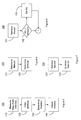
- Sound control system 17 includes a convertible top 14 for producing the artificial magnetic field intensity 12 , and a sensing system 20 for determining a convertible top position based on the artificial magnetic field intensity 12 .
- a body control module 40 adjusts a radio output parameter such as volume or equalization via radio 30 based on the convertible top position.
- sensing system 20 includes a compass 21 for measuring the magnetic field intensity 16 , and a filtering module 22 for filtering the artificial magnetic field intensity 12 from the measured magnetic field intensity 16 .
- a processing module 23 determines the convertible top position based on the artificial magnetic field intensity 12 .
- Compass 21 includes well-known electronics for measurement of magnetic field intensities and generation of a corresponding analog voltage. For example, a magneto resistive circuit (now shown) with the appropriate sensitivity can operate in conjunction with an ASIC (not shown) to produce a highly reliable analog signal.
- the filtering module 22 determines a natural magnetic field intensity 15 , and determines the artificial magnetic field intensity 12 based on the natural magnetic field intensity 15 and the measured magnetic field intensity 16 .
- filtering module 22 includes a filtering lookup table 24 containing data representing magnetic field variance information, such that the filtering module 22 determines the natural magnetic field intensity 15 based on the variance information.
- the variance information is preferably geographically dependant and is well known in the art.
- Filtering look-up table 24 can be stored in any appropriate computer readable memory such as RAM or ROM.
- Filtering module 22 and processing module 23 can be implemented via any suitable microprocessor such as any one of the Motorola MC68000 series microprocessors.
- FIG. 4 shows the preferred processing module 23 of sensing system 20 in greater detail.
- processing module 23 includes a processing look-up table 25 containing data representing a known magnetic field intensity.
- the known magnetic field intensity corresponds to a known top position.
- the processing module 23 retrieves the known magnetic field intensity from the processing look-up table 25 .
- a comparison module 26 compares the artificial magnetic field intensity to the known magnetic field intensity. For example, when the artificial magnetic field intensity equals the intensity that the convertible top is known to produce when in the up position, the comparison module 26 will set the top up bit in RAM 41 .
- the convertible top 14 may include a magnetic identification material, such as magnetic tape 18 for producing the artificial magnetic field intensity 12 .
- magnetic tape 18 could be necessary if the frame of the convertible top 14 is made of a composite material with weak or no magnetic properties. If the frame of top 14 is made of metal, however, magnetic tape 18 is not required.
- the body control module 40 selects a top up curve for the radio output parameter when the convertible top 14 is in an up position, and selects a top down curve when the convertible top 14 is in the down position.
- a method 100 for determining a position of a vehicle convertible top is shown for programming purposes.
- the method 100 includes the step 110 of measuring a magnetic field intensity, and step 120 of filtering an artificial magnetic field intensity from the measured magnetic field intensity.
- the artificial magnetic field intensity results from the convertible top.
- a convertible top position is determined based on the artificial magnetic field intensity.
- a radio output parameter such as volume is adjusted at step 140 based on the convertible top position.
- FIG. 6 shows filtering step 120 in greater detail. It will be appreciated that at step 121 a natural magnetic field intensity is determined, and at step 122 the artificial magnetic field intensity is determined based on the natural magnetic field intensity and the measured magnetic field intensity.
- the artificial magnetic field intensity is determined by retrieving the natural magnetic field intensity from a magnetic field variance chart at step 123 .
- the natural magnetic field intensity is subtracted from the measured magnetic field intensity. It is important to note that the earth generates relatively small natural magnetic field intensities as compared to the artificial magnetic field intensities generated by convertible tops. Typical measured magnetic field intensities have been found to be approximately 60 mili gauss when the convertible top is in the up position.
- FIG. 8 shows a preferred approach to determining the convertible top position. Specifically, it can be seen that at step 131 a known magnetic field intensity is retrieved, where the known magnetic field intensity corresponds to a known top position. The artificial magnetic field intensity is compared to the known magnetic field intensity at step 132 . This step reveals whether the convertible top is at the known top position. If so, the convertible top position is stored to a computer readable memory by setting the appropriate bit at step 133 . Thus, if the known magnetic field intensity corresponds to the top up position, then the top up bit will be set in the computer readable memory when the convertible top is in the up position.
- FIG. 9 demonstrates a preferred approach to adjusting the radio volume based on the convertible top position. It will be appreciated that at step 141 the appropriate bit is read from memory. At step 142 it is determined whether the top is in the up position. If so, the top up curve is selected at step 143 and transmitted to the radio signal processing system at step 144 . If it is determined at step 142 that the top is not in the up position, the top down curve is selected at step 145 . Thus, radio output parameters such as volume can be made to be a function of the convertible top position without adding switches, etc.
- a magneto resistive circuit is exposed to the magnetic field at step 111 , and a measurement voltage representing the intensity of the magnetic field is generated.
- a measurement voltage representing the intensity of the magnetic field is generated at step 112 .
- an analog measurement voltage representing the measured magnetic field intensity is generated, and a digital measurement voltage is generated at step 113 based on the analog measurement voltage.
Abstract
Description
Claims (26)
Priority Applications (1)
| Application Number | Priority Date | Filing Date | Title |
|---|---|---|---|
| US09/586,686 US6324451B1 (en) | 2000-06-01 | 2000-06-01 | Detection of the presence of a convertible top using compass electronics |
Applications Claiming Priority (1)
| Application Number | Priority Date | Filing Date | Title |
|---|---|---|---|
| US09/586,686 US6324451B1 (en) | 2000-06-01 | 2000-06-01 | Detection of the presence of a convertible top using compass electronics |
Publications (1)
| Publication Number | Publication Date |
|---|---|
| US6324451B1 true US6324451B1 (en) | 2001-11-27 |
Family
ID=24346760
Family Applications (1)
| Application Number | Title | Priority Date | Filing Date |
|---|---|---|---|
| US09/586,686 Expired - Lifetime US6324451B1 (en) | 2000-06-01 | 2000-06-01 | Detection of the presence of a convertible top using compass electronics |
Country Status (1)
| Country | Link |
|---|---|
| US (1) | US6324451B1 (en) |
Cited By (8)
| Publication number | Priority date | Publication date | Assignee | Title |
|---|---|---|---|---|
| US20040091123A1 (en) * | 2002-11-08 | 2004-05-13 | Stark Michael W. | Automobile audio system |
| US20040247141A1 (en) * | 2003-06-09 | 2004-12-09 | Holmi Douglas J. | Convertible automobile sound system equalizing |
| US20050100174A1 (en) * | 2002-11-08 | 2005-05-12 | Damian Howard | Automobile audio system |
| US20060069748A1 (en) * | 2000-01-20 | 2006-03-30 | Kabushiki Kaisha Square Enix (Also Trading As Square Enix Co., Ltd.) | Information servicing method, recording medium recording with programs for realizing the method, and information servicing system. |
| US20090110210A1 (en) * | 2007-10-29 | 2009-04-30 | Bose Corporation | Vehicle Audio System Including Door-Mounted Components |
| EP2405670A1 (en) * | 2010-07-08 | 2012-01-11 | Harman Becker Automotive Systems GmbH | Vehicle audio system with headrest incorporated loudspeakers |
| US20130304475A1 (en) * | 2012-05-14 | 2013-11-14 | General Motors Llc | Switching between acoustic parameters in a convertible vehicle |
| US20210179018A1 (en) * | 2019-12-11 | 2021-06-17 | Ford Global Technologies, Llc | Vehicle storage system |
Citations (10)
| Publication number | Priority date | Publication date | Assignee | Title |
|---|---|---|---|---|
| US4720992A (en) | 1985-12-27 | 1988-01-26 | Chrysler Motors Corporation | Calibration sequence and method for an electronic compass |
| US5208483A (en) * | 1990-06-25 | 1993-05-04 | Reneau Paul A | Automatic power-operated window and roof panel system for a motor vehicle |
| US5208866A (en) * | 1989-12-05 | 1993-05-04 | Pioneer Electronic Corporation | On-board vehicle automatic sound volume adjusting apparatus |
| US5225747A (en) * | 1992-01-06 | 1993-07-06 | Asc Incorporated | Single-button actuated self-correcting automatic convertible top |
| US5297065A (en) | 1991-12-27 | 1994-03-22 | Chrysler Corporation | Magnetic transient detection and calibration technique for an auto-calibrating compass |
| US5483692A (en) * | 1993-11-22 | 1996-01-09 | Chrysler Corporation | Automatic variable radio volume control system |
| US5550992A (en) * | 1992-07-09 | 1996-08-27 | Nec Corporation | Transmission timing control in a base station for cellular TDMA mobile communication by receiving an up-link signal for a different base station |
| US5677960A (en) | 1995-05-11 | 1997-10-14 | Victor Company Of Japan, Ltd. | On-vehicle sound control apparatus |
| US5680468A (en) * | 1995-02-21 | 1997-10-21 | Chrysler Corporation | Methods of and systems for speaker equalization in automotive vehicles having convertible tops |
| US5950722A (en) | 1998-09-04 | 1999-09-14 | Chrysler Corporation | Method for controlling an automobile climate control system and a control system useful therefor |
-
2000
- 2000-06-01 US US09/586,686 patent/US6324451B1/en not_active Expired - Lifetime
Patent Citations (10)
| Publication number | Priority date | Publication date | Assignee | Title |
|---|---|---|---|---|
| US4720992A (en) | 1985-12-27 | 1988-01-26 | Chrysler Motors Corporation | Calibration sequence and method for an electronic compass |
| US5208866A (en) * | 1989-12-05 | 1993-05-04 | Pioneer Electronic Corporation | On-board vehicle automatic sound volume adjusting apparatus |
| US5208483A (en) * | 1990-06-25 | 1993-05-04 | Reneau Paul A | Automatic power-operated window and roof panel system for a motor vehicle |
| US5297065A (en) | 1991-12-27 | 1994-03-22 | Chrysler Corporation | Magnetic transient detection and calibration technique for an auto-calibrating compass |
| US5225747A (en) * | 1992-01-06 | 1993-07-06 | Asc Incorporated | Single-button actuated self-correcting automatic convertible top |
| US5550992A (en) * | 1992-07-09 | 1996-08-27 | Nec Corporation | Transmission timing control in a base station for cellular TDMA mobile communication by receiving an up-link signal for a different base station |
| US5483692A (en) * | 1993-11-22 | 1996-01-09 | Chrysler Corporation | Automatic variable radio volume control system |
| US5680468A (en) * | 1995-02-21 | 1997-10-21 | Chrysler Corporation | Methods of and systems for speaker equalization in automotive vehicles having convertible tops |
| US5677960A (en) | 1995-05-11 | 1997-10-14 | Victor Company Of Japan, Ltd. | On-vehicle sound control apparatus |
| US5950722A (en) | 1998-09-04 | 1999-09-14 | Chrysler Corporation | Method for controlling an automobile climate control system and a control system useful therefor |
Cited By (21)
| Publication number | Priority date | Publication date | Assignee | Title |
|---|---|---|---|---|
| US20060069748A1 (en) * | 2000-01-20 | 2006-03-30 | Kabushiki Kaisha Square Enix (Also Trading As Square Enix Co., Ltd.) | Information servicing method, recording medium recording with programs for realizing the method, and information servicing system. |
| US20080122602A1 (en) * | 2002-11-08 | 2008-05-29 | Westley Brandon B | Automobile Audio System |
| US7957540B2 (en) | 2002-11-08 | 2011-06-07 | Bose Corporation | Automobile audio system |
| US7724909B2 (en) | 2002-11-08 | 2010-05-25 | Stark Michael W | Automobile audio system |
| US20050100174A1 (en) * | 2002-11-08 | 2005-05-12 | Damian Howard | Automobile audio system |
| US20040091123A1 (en) * | 2002-11-08 | 2004-05-13 | Stark Michael W. | Automobile audio system |
| US7483539B2 (en) | 2002-11-08 | 2009-01-27 | Bose Corporation | Automobile audio system |
| US20080117070A1 (en) * | 2002-11-08 | 2008-05-22 | Bose Corporation | Automobile Audio System |
| US20080117038A1 (en) * | 2002-11-08 | 2008-05-22 | Bose Corporation | Automobile Audio System |
| EP1487236A3 (en) * | 2003-06-09 | 2006-08-16 | Bose Corporation | Sound system with equalization for a convertible automobile |
| CN100375694C (en) * | 2003-06-09 | 2008-03-19 | 伯斯有限公司 | Sound system with equalization for a convertible automobile |
| US7583806B2 (en) | 2003-06-09 | 2009-09-01 | Bose Corporation | Convertible automobile sound system equalizing |
| EP1487236A2 (en) | 2003-06-09 | 2004-12-15 | Bose Corporation | Sound system with equalization for a convertible automobile |
| US20040247141A1 (en) * | 2003-06-09 | 2004-12-09 | Holmi Douglas J. | Convertible automobile sound system equalizing |
| US20090110210A1 (en) * | 2007-10-29 | 2009-04-30 | Bose Corporation | Vehicle Audio System Including Door-Mounted Components |
| US8126187B2 (en) | 2007-10-29 | 2012-02-28 | Bose Corporation | Vehicle audio system including door-mounted components |
| EP2405670A1 (en) * | 2010-07-08 | 2012-01-11 | Harman Becker Automotive Systems GmbH | Vehicle audio system with headrest incorporated loudspeakers |
| US20130304475A1 (en) * | 2012-05-14 | 2013-11-14 | General Motors Llc | Switching between acoustic parameters in a convertible vehicle |
| US9071892B2 (en) * | 2012-05-14 | 2015-06-30 | General Motors Llc | Switching between acoustic parameters in a convertible vehicle |
| US20210179018A1 (en) * | 2019-12-11 | 2021-06-17 | Ford Global Technologies, Llc | Vehicle storage system |
| US11117547B2 (en) * | 2019-12-11 | 2021-09-14 | Ford Global Technologies, Llc | Vehicle storage system |
Similar Documents
| Publication | Publication Date | Title |
|---|---|---|
| US6324451B1 (en) | Detection of the presence of a convertible top using compass electronics | |
| US4426691A (en) | Voice warning device with repeat mechanism for an automotive vehicle | |
| US5977884A (en) | Radar detector responsive to vehicle speed | |
| CA1155517A (en) | Turn signal cancelling device | |
| CA2167870A1 (en) | Remote vehicle programming system | |
| US20060006701A1 (en) | System and method for rain detection and automatic operation of power roof and power windows | |
| EP1138551A2 (en) | Infrared communication system for a vehicle and vehicle accessory operation system that utilizes the communication system | |
| CA2363472C (en) | Rearview mirror assembly with internally mounted compass sensor | |
| JPH0732948A (en) | Antificial running sound generating device for electric vehicle | |
| US20090167519A1 (en) | Vehicle signal system with audio visual control and method | |
| US7933699B2 (en) | Automatic control apparatus | |
| US6401047B1 (en) | System using information on a communications bus to eliminate magnetic noise | |
| US5950722A (en) | Method for controlling an automobile climate control system and a control system useful therefor | |
| US6684175B2 (en) | Display method of an altitude display apparatus for displaying absolute altitude | |
| KR102466861B1 (en) | Antenna apparatus and vehicle comprising the antenna apparatus | |
| EP0908338B1 (en) | Control device for motor vehicle air conditioning, with driver preferences settings | |
| US6686836B1 (en) | Device for actuating a vehicle anticrash lights based on a predetermined braking threshold | |
| US20040061597A1 (en) | Vehicle security system with multi-vehicle compatible interface module for door locks and associated methods | |
| JP2018084030A (en) | Door window closure-forgetting prevention device | |
| KR102625396B1 (en) | Vehicle and controlling method thereof | |
| JP2830543B2 (en) | Switchgear for vehicles | |
| KR20210043772A (en) | Vehicle and method for controlling the vehicle | |
| JPH0516728A (en) | On-vehicle display device | |
| JPH1024785A (en) | Space environment automatic adjusting device for automobile | |
| CN215552855U (en) | Indicator sound control system of steering lamp and vehicle |
Legal Events
| Date | Code | Title | Description |
|---|---|---|---|
| AS | Assignment |
Owner name: DAIMLERCHRYSLER CORPORATION, MICHIGAN Free format text: ASSIGNMENT OF ASSIGNORS INTEREST;ASSIGNOR:REGAN, PATRICK M.;REEL/FRAME:010913/0787 Effective date: 20000229 |
|
| STCF | Information on status: patent grant |
Free format text: PATENTED CASE |
|
| FPAY | Fee payment |
Year of fee payment: 4 |
|
| AS | Assignment |
Owner name: WILMINGTON TRUST COMPANY, DELAWARE Free format text: GRANT OF SECURITY INTEREST IN PATENT RIGHTS - FIRST PRIORITY;ASSIGNOR:CHRYSLER LLC;REEL/FRAME:019773/0001 Effective date: 20070803 Owner name: WILMINGTON TRUST COMPANY,DELAWARE Free format text: GRANT OF SECURITY INTEREST IN PATENT RIGHTS - FIRST PRIORITY;ASSIGNOR:CHRYSLER LLC;REEL/FRAME:019773/0001 Effective date: 20070803 |
|
| AS | Assignment |
Owner name: WILMINGTON TRUST COMPANY, DELAWARE Free format text: GRANT OF SECURITY INTEREST IN PATENT RIGHTS - SECOND PRIORITY;ASSIGNOR:CHRYSLER LLC;REEL/FRAME:019767/0810 Effective date: 20070803 Owner name: WILMINGTON TRUST COMPANY,DELAWARE Free format text: GRANT OF SECURITY INTEREST IN PATENT RIGHTS - SECOND PRIORITY;ASSIGNOR:CHRYSLER LLC;REEL/FRAME:019767/0810 Effective date: 20070803 |
|
| AS | Assignment |
Owner name: DAIMLERCHRYSLER COMPANY LLC, MICHIGAN Free format text: CHANGE OF NAME;ASSIGNOR:DAIMLERCHRYSLER CORPORATION;REEL/FRAME:021779/0793 Effective date: 20070329 |
|
| AS | Assignment |
Owner name: CHRYSLER LLC, MICHIGAN Free format text: CHANGE OF NAME;ASSIGNOR:DAIMLERCHRYSLER COMPANY LLC;REEL/FRAME:021826/0001 Effective date: 20070727 |
|
| AS | Assignment |
Owner name: US DEPARTMENT OF THE TREASURY, DISTRICT OF COLUMBI Free format text: GRANT OF SECURITY INTEREST IN PATENT RIGHTS - THIR;ASSIGNOR:CHRYSLER LLC;REEL/FRAME:022259/0188 Effective date: 20090102 Owner name: US DEPARTMENT OF THE TREASURY,DISTRICT OF COLUMBIA Free format text: GRANT OF SECURITY INTEREST IN PATENT RIGHTS - THIR;ASSIGNOR:CHRYSLER LLC;REEL/FRAME:022259/0188 Effective date: 20090102 |
|
| FPAY | Fee payment |
Year of fee payment: 8 |
|
| AS | Assignment |
Owner name: CHRYSLER LLC, MICHIGAN Free format text: RELEASE BY SECURED PARTY;ASSIGNOR:US DEPARTMENT OF THE TREASURY;REEL/FRAME:022902/0310 Effective date: 20090608 Owner name: CHRYSLER LLC,MICHIGAN Free format text: RELEASE BY SECURED PARTY;ASSIGNOR:US DEPARTMENT OF THE TREASURY;REEL/FRAME:022902/0310 Effective date: 20090608 |
|
| AS | Assignment |
Owner name: CHRYSLER LLC, MICHIGAN Free format text: RELEASE OF SECURITY INTEREST IN PATENT RIGHTS - FIRST PRIORITY;ASSIGNOR:WILMINGTON TRUST COMPANY;REEL/FRAME:022910/0498 Effective date: 20090604 Owner name: CHRYSLER LLC, MICHIGAN Free format text: RELEASE OF SECURITY INTEREST IN PATENT RIGHTS - SECOND PRIORITY;ASSIGNOR:WILMINGTON TRUST COMPANY;REEL/FRAME:022910/0740 Effective date: 20090604 Owner name: NEW CARCO ACQUISITION LLC, MICHIGAN Free format text: ASSIGNMENT OF ASSIGNORS INTEREST;ASSIGNOR:CHRYSLER LLC;REEL/FRAME:022915/0001 Effective date: 20090610 Owner name: THE UNITED STATES DEPARTMENT OF THE TREASURY, DIST Free format text: SECURITY AGREEMENT;ASSIGNOR:NEW CARCO ACQUISITION LLC;REEL/FRAME:022915/0489 Effective date: 20090610 Owner name: CHRYSLER LLC,MICHIGAN Free format text: RELEASE OF SECURITY INTEREST IN PATENT RIGHTS - FIRST PRIORITY;ASSIGNOR:WILMINGTON TRUST COMPANY;REEL/FRAME:022910/0498 Effective date: 20090604 Owner name: CHRYSLER LLC,MICHIGAN Free format text: RELEASE OF SECURITY INTEREST IN PATENT RIGHTS - SECOND PRIORITY;ASSIGNOR:WILMINGTON TRUST COMPANY;REEL/FRAME:022910/0740 Effective date: 20090604 Owner name: NEW CARCO ACQUISITION LLC,MICHIGAN Free format text: ASSIGNMENT OF ASSIGNORS INTEREST;ASSIGNOR:CHRYSLER LLC;REEL/FRAME:022915/0001 Effective date: 20090610 Owner name: THE UNITED STATES DEPARTMENT OF THE TREASURY,DISTR Free format text: SECURITY AGREEMENT;ASSIGNOR:NEW CARCO ACQUISITION LLC;REEL/FRAME:022915/0489 Effective date: 20090610 |
|
| AS | Assignment |
Owner name: CHRYSLER GROUP LLC, MICHIGAN Free format text: CHANGE OF NAME;ASSIGNOR:NEW CARCO ACQUISITION LLC;REEL/FRAME:022919/0126 Effective date: 20090610 Owner name: CHRYSLER GROUP LLC,MICHIGAN Free format text: CHANGE OF NAME;ASSIGNOR:NEW CARCO ACQUISITION LLC;REEL/FRAME:022919/0126 Effective date: 20090610 |
|
| AS | Assignment |
Owner name: CHRYSLER GROUP LLC, MICHIGAN Free format text: RELEASE BY SECURED PARTY;ASSIGNOR:THE UNITED STATES DEPARTMENT OF THE TREASURY;REEL/FRAME:026343/0298 Effective date: 20110524 Owner name: CHRYSLER GROUP GLOBAL ELECTRIC MOTORCARS LLC, NORT Free format text: RELEASE BY SECURED PARTY;ASSIGNOR:THE UNITED STATES DEPARTMENT OF THE TREASURY;REEL/FRAME:026343/0298 Effective date: 20110524 |
|
| AS | Assignment |
Owner name: CITIBANK, N.A., NEW YORK Free format text: SECURITY AGREEMENT;ASSIGNOR:CHRYSLER GROUP LLC;REEL/FRAME:026404/0123 Effective date: 20110524 |
|
| AS | Assignment |
Owner name: CITIBANK, N.A., NEW YORK Free format text: SECURITY AGREEMENT;ASSIGNOR:CHRYSLER GROUP LLC;REEL/FRAME:026435/0652 Effective date: 20110524 |
|
| FPAY | Fee payment |
Year of fee payment: 12 |
|
| AS | Assignment |
Owner name: JPMORGAN CHASE BANK, N.A., ILLINOIS Free format text: SECURITY AGREEMENT;ASSIGNOR:CHRYSLER GROUP LLC;REEL/FRAME:032384/0640 Effective date: 20140207 |
|
| AS | Assignment |
Owner name: FCA US LLC, MICHIGAN Free format text: CHANGE OF NAME;ASSIGNOR:CHRYSLER GROUP LLC;REEL/FRAME:035553/0356 Effective date: 20141203 |
|
| AS | Assignment |
Owner name: FCA US LLC, FORMERLY KNOWN AS CHRYSLER GROUP LLC, Free format text: RELEASE OF SECURITY INTEREST RELEASING SECOND-LIEN SECURITY INTEREST PREVIOUSLY RECORDED AT REEL 026426 AND FRAME 0644, REEL 026435 AND FRAME 0652, AND REEL 032384 AND FRAME 0591;ASSIGNOR:CITIBANK, N.A.;REEL/FRAME:037784/0001 Effective date: 20151221 |
|
| AS | Assignment |
Owner name: FCA US LLC (FORMERLY KNOWN AS CHRYSLER GROUP LLC), Free format text: RELEASE BY SECURED PARTY;ASSIGNOR:CITIBANK, N.A.;REEL/FRAME:042885/0255 Effective date: 20170224 |
|
| AS | Assignment |
Owner name: FCA US LLC (FORMERLY KNOWN AS CHRYSLER GROUP LLC), Free format text: RELEASE BY SECURED PARTY;ASSIGNOR:JPMORGAN CHASE BANK, N.A.;REEL/FRAME:048177/0356 Effective date: 20181113 |